34
Technical Guide echnical Guide echnical Guide echnical Guide echnical Guide Desiccant Wheel Products Energy Recovery Wheel

TTTTTechnical Guideechnical Guideechnical Guideechnical Guideechnical Guide
Desiccant Wheel Products
Energy Recovery Wheel

Table of Contents
i • Energy Recovery Wheel Technical Guide
© SEMCO Incorporated 1990-2003. All rights reserved.
The information in this technical guide is furnished for informational use only, is subject to change without notice, andshould not be construed as a commitment by SEMCO Incorporated. SEMCO Incorporated assumes no responsibility forany errors that may appear in this technical guide.
No part of this publication may be reproduced, stored in a retrieval system or transmitted, in any form or by any means,electronic, mechanical, recording, or otherwise, without the prior written permission of SEMCO Incorporated.
U.S. patented technology: 5,401,706 ; 5,496,397 ; 4,769,053
EXCLU-SIEVE® and SEMCO Incorporated are registered trademarks of SEMCO Incorporated.
Introduction ........................................................................................... 1The Ventilation Mandate ...................................................................... 1Typical Applications ............................................................................... 2Benefits................................................................................................... 2Design Features ..................................................................................... 3Recovering Total Energy ........................................................................ 6Recovering Sensible Only ...................................................................... 7Unit Selection ........................................................................................ 8Unit Selection Example ...................................................................... 11Purge Section ....................................................................................... 14Fan Location Options.......................................................................... 16Drive Motor Location.......................................................................... 16Filtration Requirements ...................................................................... 17Odors and Contaminants .................................................................... 18Wheel Speed Control .......................................................................... 19
Preheating to Avoid Frost Formation ........................................... 20Controlling Wheel Speed To Avoid Frost Formation ................. 20Avoiding Overheating (Economizer Cycle) ................................. 21Automatic Summer-Winter Change Over ................................... 21Condensation on Sensible Only Wheels ..................................... 21
Sensible Wheel Performance .............................................................. 22Sensible Wheel Applications .............................................................. 23Condensation & Frosting .................................................................... 23Cleaning The Wheel Media ............................................................... 24Installation Guidelines ........................................................................ 24Typical Wiring Schematic ................................................................... 25Mounting Arrangements ..................................................................... 26Wheel Drive Options .......................................................................... 26Ordering Key ........................................................................................ 27Performance Data for TE3 and TS Wheels ....................................... 28Unit Dimensions.................................................................................. 28Sample Specification ........................................................................... 29How to Reach SEMCO ....................................................................... 30Wheel Configuration Checklist .......................................................... 31Psychrometric Chart ............................................................................ 32
Energy Recovery Wheel Technical Guide • 1
ASHRAE Standard 62-1999, Ventilation for Acceptable Indoor AirQuality, defines the minimum outdoor air ventilation rates required toachieve acceptable indoor air quality. This standard, which is referencedin part or whole by all building codes in the United States, recommendsthat outdoor air quantities be increased from 5 cfm per person to 20cfm per person (in an office environment) to avoid adverse health effects.Although most owners, architects and engineers recognize the benefitsof bringing in more outdoor air, many are concerned about the impacton equipment and operating costs.
EXCLU-SIEVE® provides the solution to the ASHRAE 62-1999mandate. It precools and dehumidifies the outdoor air during the coolingseason and preheats and humidifies the outdoor air during the heatingseason. As a result, the outdoor air quantity can be increased from 5 to20 cfm per person without increasing energy costs.
As importantly, the first cost savings associated with the reductionin chiller and heating/humidification capacity typically pay for the addedcost associated with the installation of the total energy recoveryequipment.
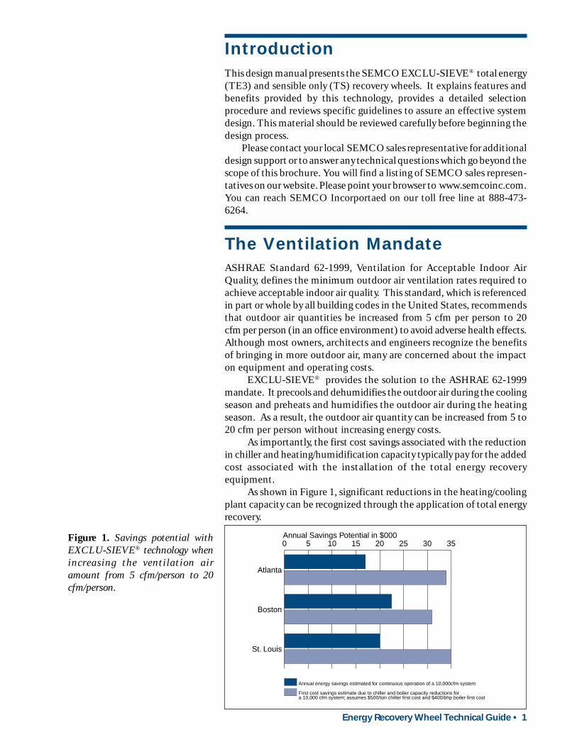
As shown in Figure 1, significant reductions in the heating/coolingplant capacity can be recognized through the application of total energyrecovery.
The Ventilation Mandate
IntroductionThis design manual presents the SEMCO EXCLU-SIEVE® total energy(TE3) and sensible only (TS) recovery wheels. It explains features andbenefits provided by this technology, provides a detailed selectionprocedure and reviews specific guidelines to assure an effective systemdesign. This material should be reviewed carefully before beginning thedesign process.
Please contact your local SEMCO sales representative for additionaldesign support or to answer any technical questions which go beyond thescope of this brochure. You will find a listing of SEMCO sales represen-tatives on our website. Please point your browser to www.semcoinc.com.You can reach SEMCO Incorportaed on our toll free line at 888-473-6264.
Figure 1. Savings potential withEXCLU-SIEVE® technology whenincreasing the ventilation airamount from 5 cfm/person to 20cfm/person.
0 5 10 15 20 25 30 35
First cost savings estimate due to chiller and boiler capacity reductions for a 10,000 cfm system; assumes $500/ton chiller first cost and $400/bhp boiler first cost
Annual energy savings estimated for continuous operation of a 10,000cfm system
St. Louis
Boston
Atlanta
Annual Savings Potential in $000
2 • Energy Recovery Wheel Technical Guide
Energy recovery equipment can be applied to a wide variety ofapplications:
• Schools, universities, dormitories;• offices, condominiums, apartments;• smoking lounges, casinos;• hospitals, nursing homes, day care centers;• hotels, motels, department stores;• clean rooms, circuit board, chip manufacturing;• breweries;• swimming pools, sports arenas;• convention centers, airports, prisons;• bus and train maintenance facilities;• welding, foundry, casting areas;• printing operations;• all humidity controlled spaces; and• product drying operations.
Typical Applications
The SEMCO EXCLU-SIEVE® technology affords a number of benefits:
• Independently certified wheel performance.• Equal latent and sensible heat transfer.• Highest effectiveness for given size equipment.• Virtually no cross-contamination (independently certified to be
less than 0.04 percent).• Field adjustable purge section.• Wheel independently certified to pass NFPA 90A requirements for
flame spread and smoke generation based upon ASTM E84 fire testmethod.
• Reliable operation.• Low maintenance.• Low operating costs.• Long life expectancy.• Can be applied where stationary heat exchangers cannot.
Benefits
Energy Recovery Wheel Technical Guide • 3
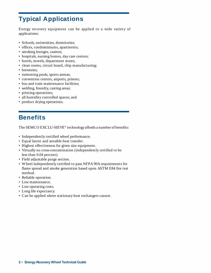
Media may beinstalled or removed
through a standardaccess door
Heavy Wall I-BeamShape ExtrudedAluminum Spoke
Heavy WallExtrudedAluminum Rim
ExtrudedAluminum
Hub
Hub & Spoke Construction Detail
External PillowBlock Bearings
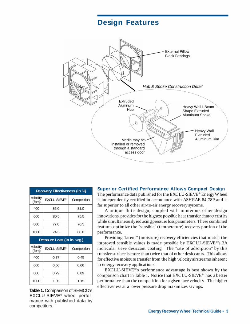
Superior Certified Performance Allows Compact DesignThe performance data published for the EXCLU-SIEVE® Energy Wheelis independently certified in accordance with ASHRAE 84-78P and isfar superior to all other air-to-air energy recovery systems.
A unique flute design, coupled with numerous other designinnovations, provides for the highest possible heat transfer characteristicswhile simultaneously reducing pressure loss parameters. These combinedfeatures optimize the "sensible" (temperature) recovery portion of theperformance.
Providing "latent" (moisture) recovery efficiencies that match theimproved sensible values is made possible by EXCLU-SIEVE®'s 3Åmolecular sieve desiccant coating. The "rate of adsorption" by thistransfer surface is more than twice that of other desiccants. This allowsfor effective moisture transfer from the high velocity airstreams inherentin energy recovery applications.
EXCLU-SIEVE®'s performance advantage is best shown by thecomparison chart in Table 1. Notice that EXCLU-SIEVE® has a betterperformance than the competition for a given face velocity. The highereffectiveness at a lower pressure drop maximizes savings.
TTTTTable 1.able 1.able 1.able 1.able 1. Comparison of SEMCO'sEXCLU-SIEVE® wheel perfor-mance with published data bycompetitors.
Design Features
)%ni(ssenevitceffEyrevoceR
yticoleV)mpf(
EVEIS-ULCXE ® noititepmoC
004 0.68 0.18
006 5.08 5.57
008 0.77 5.07
0001 5.47 0.66
).g.w.nini(ssoLerusserP
yticoleV)mpf(
EVEIS-ULCXE ® noititepmoC
004 73.0 54.0
006 65.0 66.0
008 97.0 98.0
0001 50.1 51.1

4 • Energy Recovery Wheel Technical Guide
.
.
3Å Molecular Sieve Desiccant CoatingThe EXCLU-SIEVE® wheel utilizes a 3Å molecular sieve desiccantcoating to limit the risk of desiccant cross-contamination which wouldotherwise cause a portion of the exhaust air pollutants to be transferred,along with the water vapor, to the fresh airstream.
The 3Å molecular sieve material utilized by SEMCO was developedspecifically for “selective adsorption” and has been successfully used fordecades by the petrochemical industry. Other desiccants like silica geland oxidized aluminum cannot provide selective adsorption.
Molecular sieves are structurally stable, chemically inert and have astrong affinity for water vapor. This strong affinity for water vaporproduces the high rate of adsorption which provides superior latenttransfer performance.
Non-oxidized Coated Media ConstructionThe EXCLU-SIEVE® media is made from aluminum which is evenlycoated, prior to being formed into its honeycomb configuration, with adense layer of corrosion resistant desiccant. This extends the life of thealuminum media substrate and enhances its structural integrity. This isin sharp contrast to most other total energy wheels which are producedby oxidizing the surface of the aluminum substrate to form a crudedesiccant which leaves the product susceptible to further oxidation anddiminishes its structural integrity.
Modular Media Sections with Aluminum Spoke SupportSystemThe media support system is made from aluminum extrusions. Thisprovides the substantial structural backbone required to withstand theforces encountered during a wheel's 10,000,000 annual revolutions(assuming continuous operation).
The use of aluminum drastically reduces the weight of the rotorwhen compared to a steel support system. The result is a more evenlybalanced rotor which reduces wear and tear on the drive system andbearings.
The tolerances obtainable from an extruded media support structureallow for the flattest possible sealing surface. This adds significantly tothe integrity of the total sealing system.
Service Free Drive and Control SystemA responsive and maintenance-free drive system is an integral part ofany rotary heat exchanger. The drive system standard with any EXCLU-SIEVE® unit is an AC constant or variable speed system with drivebelts.
.

Energy Recovery Wheel Technical Guide • 5
.
.
Non-wearing Extruded Labyrinth SealsEXCLU-SIEVE® utilizes a four pass labyrinth seal which has beendesigned to give optimum performance under the pressure conditionsencountered in this application. Since the seals never actually touch therotating surface, their life is indefinite. All seals are easily field adjustable.This efficient sealing system increases performance and virtuallyeliminates carryover of contaminants from the return airstream to thesupply airstream.
Tubular Steel Casing ConstructionTo avoid deflection of the energy wheel casing due to the significanttorque imposed by the air pressure on the energy wheel surface, a tubularsteel framework is used. Casing deflection is undesired since it increasesthe gap between the seals and the wheel surface causing excessive airleakage.
Built-in Bearing Replacement SystemThe bearings used in the EXCLU-SIEVE® units provide a long life withminimal maintenance. The external pillow block bearings simplify anyreplacements should this ever become necessary. The rotor remains inthe casing and none of the rotor or media has to be removed.
Optional Extended Service ContractThe EXCLU-SIEVE® units are designed to provide long and reliableoperation. As a statement of our commitment to quality, the EXCLU-SIEVE® wheels are available with an optional extended service contractto cover any unforeseen mechanical deficiencies or performancedegradations. The coverage period can be as long as five years.
Complete details can be obtained from your local SEMCO salesrepresentative.
Air flowing between the rotor and labyrinthseal expands repeatedly, creating apressure loss that forms an effective sealand prevents air from bypassing the rotor.The labyrinth seal never touches the rotor.
Rotor
Seal
6 • Energy Recovery Wheel Technical Guide
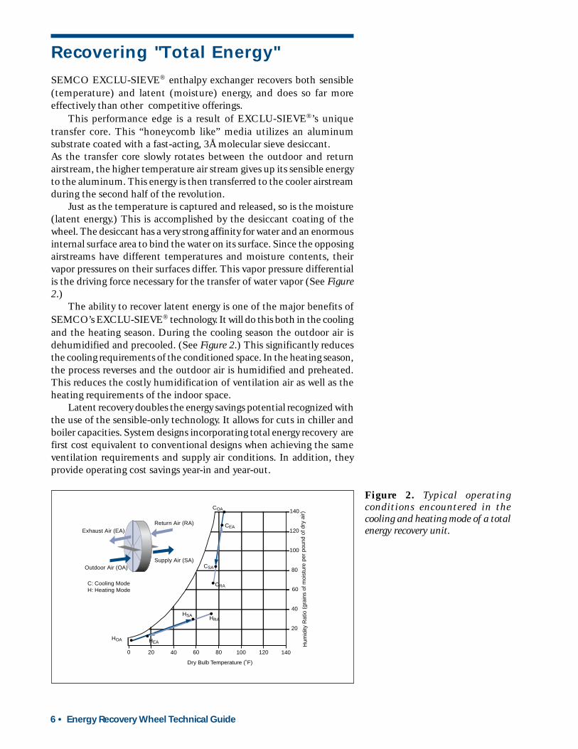
Figure 2. Typical operatingconditions encountered in thecooling and heating mode of a totalenergy recovery unit.
Recovering "Total Energy"
SEMCO EXCLU-SIEVE® enthalpy exchanger recovers both sensible(temperature) and latent (moisture) energy, and does so far moreeffectively than other competitive offerings.
This performance edge is a result of EXCLU-SIEVE®’s uniquetransfer core. This “honeycomb like” media utilizes an aluminumsubstrate coated with a fast-acting, 3Å molecular sieve desiccant.As the transfer core slowly rotates between the outdoor and returnairstream, the higher temperature air stream gives up its sensible energyto the aluminum. This energy is then transferred to the cooler airstreamduring the second half of the revolution.
Just as the temperature is captured and released, so is the moisture(latent energy.) This is accomplished by the desiccant coating of thewheel. The desiccant has a very strong affinity for water and an enormousinternal surface area to bind the water on its surface. Since the opposingairstreams have different temperatures and moisture contents, theirvapor pressures on their surfaces differ. This vapor pressure differentialis the driving force necessary for the transfer of water vapor (See Figure2.)
The ability to recover latent energy is one of the major benefits ofSEMCO’s EXCLU-SIEVE® technology. It will do this both in the coolingand the heating season. During the cooling season the outdoor air isdehumidified and precooled. (See Figure 2.) This significantly reducesthe cooling requirements of the conditioned space. In the heating season,the process reverses and the outdoor air is humidified and preheated.This reduces the costly humidification of ventilation air as well as theheating requirements of the indoor space.
Latent recovery doubles the energy savings potential recognized withthe use of the sensible-only technology. It allows for cuts in chiller andboiler capacities. System designs incorporating total energy recovery arefirst cost equivalent to conventional designs when achieving the sameventilation requirements and supply air conditions. In addition, theyprovide operating cost savings year-in and year-out.
1008020 40 600 140120
120
100
80
40
60
20
Dry Bulb Temperature (˚F)
Hum
idity
Rat
io (
grai
ns o
f moi
stur
e pe
r po
und
of d
ry a
ir)
COA
CEA
CRA
CSA
HOA
HRA
HEA
HSA
Outdoor Air (OA)Supply Air (SA)
Return Air (RA)Exhaust Air (EA)
C: Cooling ModeH: Heating Mode
140
Energy Recovery Wheel Technical Guide • 7
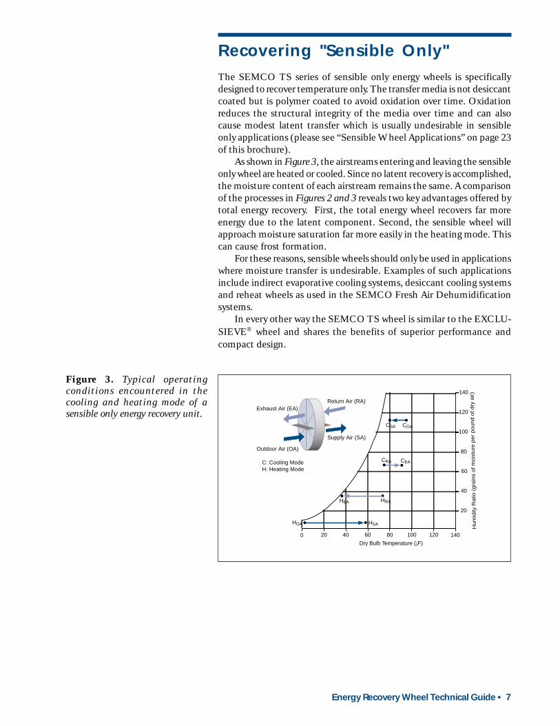
The SEMCO TS series of sensible only energy wheels is specificallydesigned to recover temperature only. The transfer media is not desiccantcoated but is polymer coated to avoid oxidation over time. Oxidationreduces the structural integrity of the media over time and can alsocause modest latent transfer which is usually undesirable in sensibleonly applications (please see “Sensible Wheel Applications” on page 23of this brochure).
As shown in Figure 3, the airstreams entering and leaving the sensibleonly wheel are heated or cooled. Since no latent recovery is accomplished,the moisture content of each airstream remains the same. A comparisonof the processes in Figures 2 and 3 reveals two key advantages offered bytotal energy recovery. First, the total energy wheel recovers far moreenergy due to the latent component. Second, the sensible wheel willapproach moisture saturation far more easily in the heating mode. Thiscan cause frost formation.
For these reasons, sensible wheels should only be used in applicationswhere moisture transfer is undesirable. Examples of such applicationsinclude indirect evaporative cooling systems, desiccant cooling systemsand reheat wheels as used in the SEMCO Fresh Air Dehumidificationsystems.
In every other way the SEMCO TS wheel is similar to the EXCLU-SIEVE® wheel and shares the benefits of superior performance andcompact design.
Recovering "Sensible Only"
Figure 3. Typical operatingconditions encountered in thecooling and heating mode of asensible only energy recovery unit.
1008020 40 600 140120
120
100
80
40
60
20
Dry Bulb Temperature (¡F)
Hum
idity
Rat
io (
grai
ns o
f moi
stur
e pe
r po
und
of d
ry a
ir)
COA
CEACRA
CSA
HOA
HRAHEA
HSA
Outdoor Air (OA)
Supply Air (SA)
Return Air (RA)Exhaust Air (EA)
C: Cooling ModeH: Heating Mode
140

8 • Energy Recovery Wheel Technical Guide
Figure 4. Performance charts for TE3Series Total Energy Recovery Wheels.
1 Wheel Selection
Wheel selection is based on face velocity. The energy recovery wheelhas been optimized for a face velocity of about 800. This achieves thebest balance between energy recovery effectiveness, pressure loss andfirst cost.
Using the EXCLU-SIEVE® Performance Chart (See Figure 4), findthe desired airflow volume on the left hand margin of the performancechart. Selection is always based on the smaller of the supply or returnairflow when using unequal airflows. Read across until intersecting theappropriate EXCLU-SIEVE® TE3 model number, then read down toobtain the face velocity. Reading down the chart further will give theassociated pressure loss for this face velocity. This procedure must berepeated at the larger airflow volume to determine the pressure loss forthe opposite airstream in unequal flow applications.
Unit Selection
706050
40
30
20
02
468
10
15
400 500 600 700 800 9001000
1100
TE3-3
TE3-5
TE3-9
TE3-13TE3-18TE3-24
TE3-28
TE3-35
TE3-43
TE3-46
TE3-56
TE3-70
AIR
FLO
W (S
CFM
X T
HO
USA
ND
)
PRESSURE LOSS (IN. WG.)
EFFE
CTI
VEN
ESS
(%)
(Rat
ed a
t Min
imum
Airf
low
Vol
ume)
FACE VELOCITY (FPM)
FACE VELOCITY (FPM)
.35.40
.50.60
.70.80
.901.0
1.101.23
95
90
85
80
75
0400 500 600 700 800 9001000
1100
1.0.9.8.7.6.5
FLOWRATIO
Vmin/Vmax
TOTAL ENERGY RECOVERY WHEEL SIZE
Energy Recovery Wheel Technical Guide • 9
2 Unit Effectiveness
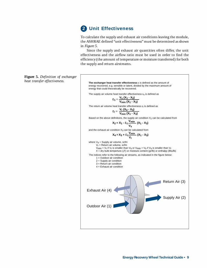
To calculate the supply and exhaust air conditions leaving the module,the ASHRAE defined “unit effectiveness” must be determined as shownin Figure 5.
Since the supply and exhaust air quantities often differ, the uniteffectiveness and the airflow ratio must be used in order to find theefficiency (the amount of temperature or moisture transferred) for boththe supply and return airstreams.
Figure 5. Definition of exchangerheat transfer effectiveness.
Outdoor Air (1)
Supply Air (2)
Return Air (3)
Exhaust Air (4)
Vs (X1 - X2)εs =Vmin (X1 - X3)
Vr (X4 - X3)Vmin (X1 - X3)
εr =
The exchanger heat transfer effectiveness ε is defined as the amount of energy recovered, e.g. sensible or latent, divided by the maximum amount of energy that could theoratically be recovered.
The supply air volume heat transfer effectiveness εs is defined as
The return air volume heat transfer effectiveness εr is defined as
where Vs = Supply air volume, scfmVr = Return air volume, scfmVmin = Vr if Vr is smaller than Vs or Vmin = Vs if Vs is smaller than VrX = dry bulb temperture (¡F) or moisture content (gr/lb) or enthalpy (Btu/lb)
The indices refer to the following air streams, as indicated in the figure below:1 = Outdoor air condition2 = Supply air condition3 = Return air condition4 = Exhaust air condition
Based on the above definitions, the supply air condition X2 can be calculated from
and the exhaust air condition X3 can be calculated from
Vs
Vmin (X1 - X3)X2 = X1 - εs
Vr
Vmin (X1 - X3)X4 = X3 + εs
10 • Energy Recovery Wheel Technical Guide
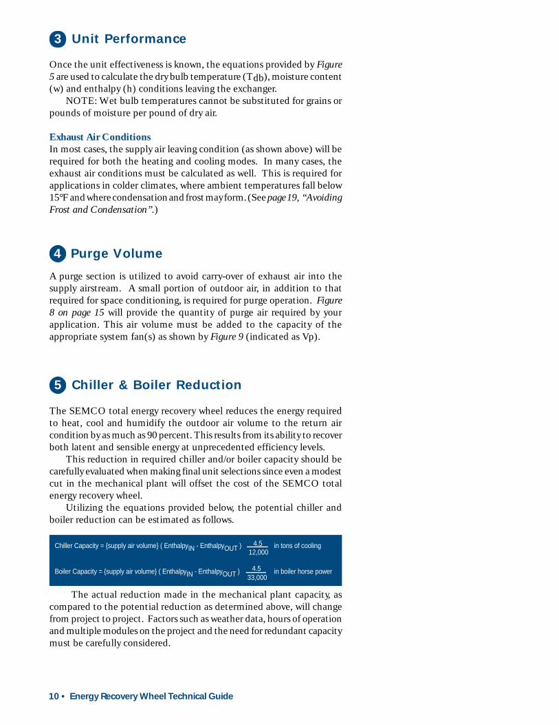
5 Chiller & Boiler Reduction
The SEMCO total energy recovery wheel reduces the energy requiredto heat, cool and humidify the outdoor air volume to the return aircondition by as much as 90 percent. This results from its ability to recoverboth latent and sensible energy at unprecedented efficiency levels.
This reduction in required chiller and/or boiler capacity should becarefully evaluated when making final unit selections since even a modestcut in the mechanical plant will offset the cost of the SEMCO totalenergy recovery wheel.
Utilizing the equations provided below, the potential chiller andboiler reduction can be estimated as follows.
The actual reduction made in the mechanical plant capacity, ascompared to the potential reduction as determined above, will changefrom project to project. Factors such as weather data, hours of operationand multiple modules on the project and the need for redundant capacitymust be carefully considered.
A purge section is utilized to avoid carry-over of exhaust air into thesupply airstream. A small portion of outdoor air, in addition to thatrequired for space conditioning, is required for purge operation. Figure8 on page 15 will provide the quantity of purge air required by yourapplication. This air volume must be added to the capacity of theappropriate system fan(s) as shown by Figure 9 (indicated as Vp).
4 Purge Volume
3 Unit Performance
Once the unit effectiveness is known, the equations provided by Figure5 are used to calculate the dry bulb temperature (Tdb), moisture content(w) and enthalpy (h) conditions leaving the exchanger.
NOTE: Wet bulb temperatures cannot be substituted for grains orpounds of moisture per pound of dry air.
Exhaust Air ConditionsIn most cases, the supply air leaving condition (as shown above) will berequired for both the heating and cooling modes. In many cases, theexhaust air conditions must be calculated as well. This is required forapplications in colder climates, where ambient temperatures fall below15°F and where condensation and frost may form. (See page 19, “AvoidingFrost and Condensation”.)
Chiller Capacity = {supply air volume} ( EnthalpyIN - EnthalpyOUT ) in tons of cooling4.512,000
Boiler Capacity = {supply air volume} ( EnthalpyIN - EnthalpyOUT ) in boiler horse power4.533,000
Energy Recovery Wheel Technical Guide • 11
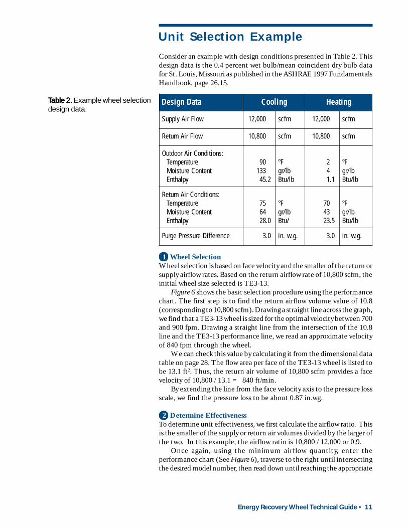
Consider an example with design conditions presented in Table 2. Thisdesign data is the 0.4 percent wet bulb/mean coincident dry bulb datafor St. Louis, Missouri as published in the ASHRAE 1997 FundamentalsHandbook, page 26.15.
Unit Selection Example
ataDngiseD ataDngiseD ataDngiseD ataDngiseD ataDngiseD gnilooC gnilooC gnilooC gnilooC gnilooC gnitaeH gnitaeH gnitaeH gnitaeH gnitaeH
wolFriAylppuS 000,21 mfcs 000,21 mfcs
wolFriAnruteR 008,01 mfcs 008,01 mfcs
:snoitidnoCriAroodtuOerutarepmeT
tnetnoCerutsioMyplahtnE
09331
2.54
F°bl/rgbl/utB
24
1.1
F°bl/rgbl/utB
:snoitidnoCriAnruteRerutarepmeT
tnetnoCerutsioMyplahtnE
5746
0.82
F°bl/rg/utB
0734
5.32
F°bl/rgbl/utB
ecnereffiDerusserPegruP 0.3 .g.w.ni 0.3 .g.w.ni
TTTTTable 2.able 2.able 2.able 2.able 2. Example wheel selectiondesign data.
1 Wheel SelectionWheel selection is based on face velocity and the smaller of the return orsupply airflow rates. Based on the return airflow rate of 10,800 scfm, theinitial wheel size selected is TE3-13.
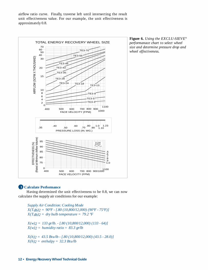
Figure 6 shows the basic selection procedure using the performancechart. The first step is to find the return airflow volume value of 10.8(corresponding to 10,800 scfm). Drawing a straight line across the graph,we find that a TE3-13 wheel is sized for the optimal velocity between 700and 900 fpm. Drawing a straight line from the intersection of the 10.8line and the TE3-13 performance line, we read an approximate velocityof 840 fpm through the wheel.
We can check this value by calculating it from the dimensional datatable on page 28. The flow area per face of the TE3-13 wheel is listed tobe 13.1 ft2. Thus, the return air volume of 10,800 scfm provides a facevelocity of 10,800 / 13.1 = 840 ft/min.
By extending the line from the face velocity axis to the pressure lossscale, we find the pressure loss to be about 0.87 in.wg.
2 Determine EffectivenessTo determine unit effectiveness, we first calculate the airflow ratio. Thisis the smaller of the supply or return air volumes divided by the larger ofthe two. In this example, the airflow ratio is 10,800 / 12,000 or 0.9.
Once again, using the minimum airflow quantity, enter theperformance chart (See Figure 6), traverse to the right until intersectingthe desired model number, then read down until reaching the appropriate
12 • Energy Recovery Wheel Technical Guide
3 Calculate PerformanceHaving determined the unit effectiveness to be 0.8, we can now
calculate the supply air conditions for our example:
Supply Air Condition: Cooling ModeX(Tdb)2 = 90°F - [.80 (10,800/12,000) (90°F - 75°F)]X(Tdb)2 = dry bulb temperature = 79.2 °F
X(w)2 = 133 gr/lb. - [.80 (10,800/12,000) (133 - 64)]X(w)2 = humidity ratio = 83.3 gr/lb
X(h)2 = 43.5 Btu/lb - [.80 (10,800/12,000) (43.5 - 28.0)]X(h)2 = enthalpy = 32.3 Btu/lb
Figure 6. Using the EXCLU-SIEVE®
performanace chart to select wheelsize and determine pressure drop andwheel effectiveness.
airflow ratio curve. Finally, traverse left until intersecting the resultunit effectiveness value. For our example, the unit effectiveness isapproximately 0.8.
706050
40
30
20
02
468
10
15
400 500 600 700 800 9001000
1100
TE3-3
TE3-5
TE3-9
TE3-13TE3-18TE3-24
TE3-28
TE3-35
TE3-43
TE3-46
TE3-56
TE3-70
AIRF
LOW
(SCF
M X
THO
USAN
D)
PRESSURE LOSS (IN. WG.)
EFFE
CTIV
ENES
S (%
)(R
ated
at M
inim
um A
irflo
w Vo
lum
e)
FACE VELOCITY (FPM)
FACE VELOCITY (FPM)
.35.40
.50.60
.70.80
.901.0
1.101.23
95
90
85
80
75
0400 500 600 700 800 9001000
1100
1.0.9.8.7.6.5
FLOWRATIO
Vmin/Vmax
TOTAL ENERGY RECOVERY WHEEL SIZE
Energy Recovery Wheel Technical Guide • 13
Supply Air Condition: Heating ModeX(Tdb)2 = 2°F - [.80 (10,800/12,000) (2°F - 70°F)]X(Tdb)2 = dry bulb temperature= 51.0 °F
X(w)2 = 4 gr/lb - [.80 (10,800/12,000) (4 - 43) gr/lb]X(w)2 = humidity ratio = 32.1 gr/lb
X(h)2 = 1.1 Btu/lb - [.80 (10,800/12,000) (1.1 - 23.5)]X(h)2 = enthalpy = 17.2 Btu/lb
4 Determine Purge VolumeFrom Table 2 we know that the purge pressure difference is 3 in.wg.Using the procedure described on page 15 and Figure 8, we estimate thepurge volume to be about 1,100 scfm.
5 Potential Chiller and Boiler ReductionC = [12,000 scfm x 4.5 x (43.5 - 32.3) Btu/lb]/12,000 btu/tonC = Chiller reduction capacity = 50.4 tons
B = [12,000 scfm x 4.5 x (17.2 - 1.1) btu/lb]/33,000 btu/bhpB = Boiler reduction capacity = 26.4 boiler h.p.
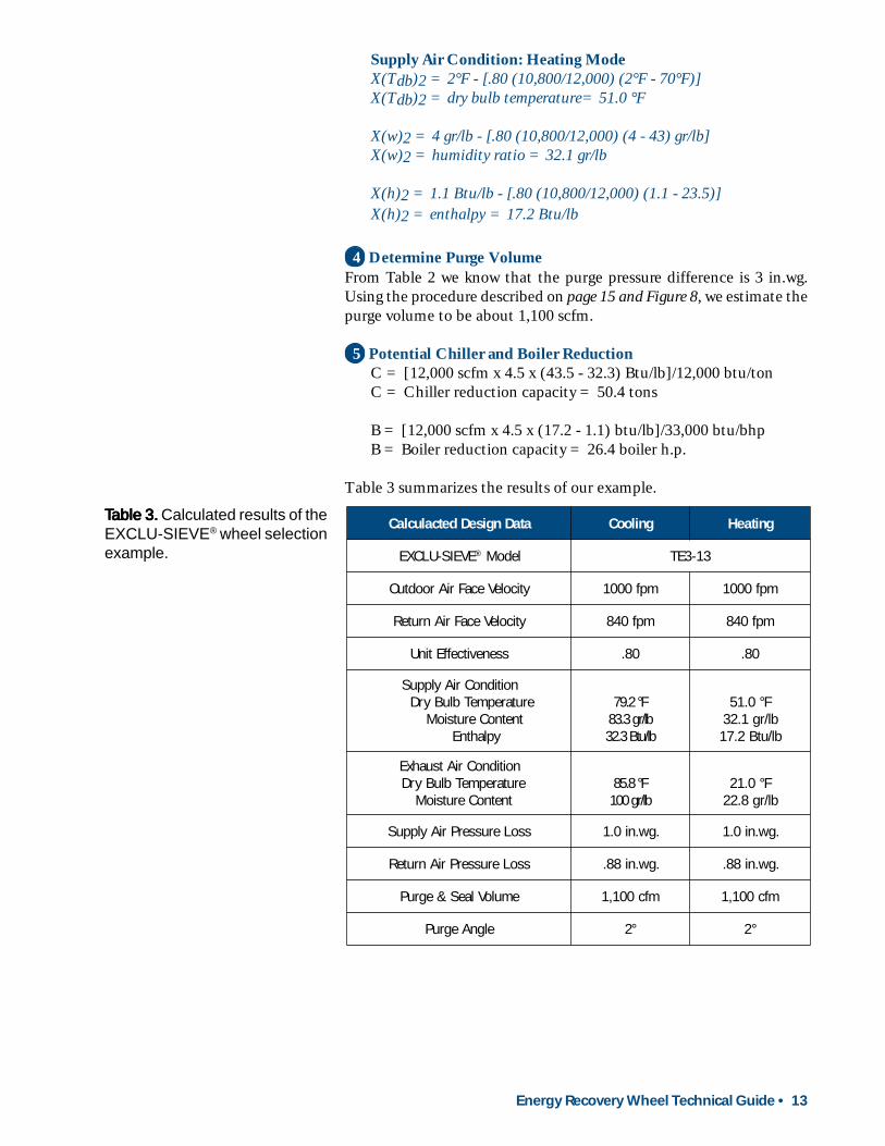
Table 3 summarizes the results of our example.
TTTTTable 3.able 3.able 3.able 3.able 3. Calculated results of theEXCLU-SIEVE® wheel selectionexample.
ataDngiseDdetcaluclaC gnilooC gnitaeH
EVEIS-ULCXE ® ledoM 31-3ET
yticoleVecaFriAroodtuO mpf0001 mpf0001
yticoleVecaFriAnruteR mpf048 mpf048
ssenevitceffEtinU 08. 08.
noitidnoCriAylppuSerutarepmeTbluByrD
tnetnoCerutsioMyplahtnE
F°2.97bl/rg3.38bl/utB3.23
F°0.15bl/rg1.23bl/utB2.71
noitidnoCriAtsuahxEerutarepmeTbluByrD
tnetnoCerutsioMF°8.58bl/rg001
F°0.12bl/rg8.22
ssoLerusserPriAylppuS .gw.ni0.1 .gw.ni0.1
ssoLerusserPriAnruteR .gw.ni88. .gw.ni88.
emuloVlaeS&egruP mfc001,1 mfc001,1
elgnAegruP °2 °2

14 • Energy Recovery Wheel Technical Guide
Purge Section
As energy recovery wheel rotates from the exhaust airstream into thesupply airstream, a small amount of the exhaust air is traversing theflutes of the wheel media as it passes by the seal separating the twoairstreams. If this volume of exhaust air were allowed to mix with theclean supply airstream, “cross-contamination” would occur.
Cross-contamination is virtually eliminated by a “purge section”,which is an integral part of the casing design. The purge section utilizesthe pressure difference which exists between the outdoor and returnairstreams to “purge” the transfer media with clean outdoor air prior toits rotation into the supply airstream. Figure 7 provides a graphicrepresentation of the purge section operation.
The purge section is adjustable. This allows for optimizing therequired purge volume during system startup, regardless of the pressuredifference between the outdoor and return airstreams (provided thatthe return air pressure is lower than that of the outdoor air).
Figure 7. Schematic of the purgeoperation.
Operation
Exhaust Air
Return Air
Outdoor Air
Supply Air
Purge Air
Rotation Direction
Energy Recovery Wheel Technical Guide • 15
Selection
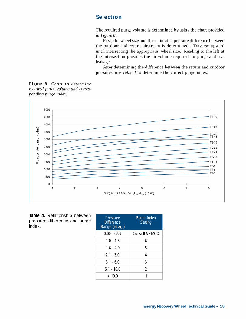
The required purge volume is determined by using the chart providedin Figure 8.
First, the wheel size and the estimated pressure difference betweenthe outdoor and return airstream is determined. Traverse upwarduntil intersecting the appropriate wheel size. Reading to the left atthe intersection provides the air volume required for purge and sealleakage.
After determining the difference between the return and outdoorpressures, use Table 4 to determine the correct purge index.
Figure 8. Chart to determinerequired purge volume and corres-ponding purge index.
0
500
1000
1500
2000
2500
3000
3500
4000
4500
5000
1 2 3 4 5 6 7 8
P u rge P re s s u re (P -P ) in.wg.
Pu
rge
Vo
lum
e (
cfm
)
TE-3TE-5TE-9
TE-13
TE-18
TE-24TE-28
TE-35
TE-43TE-46
TE-56
TE-70
OA RA
TTTTTable 4. able 4. able 4. able 4. able 4. Relationship betweenpressure difference and purgeindex.
erusserPecnereffiD
).gw.ni(egnaR
xednIegruPgnitteS
99.0-00.0 OCMEStlusnoC5.1-0.1 60.2-6.1 50.3-1.2 40.6-1.3 30.01-1.6 2
0.01> 1
16 • Energy Recovery Wheel Technical Guide
OUTDOOR AIR = VS + VP SUPPLY AIR = VS
RETURN AIR = VREXHAUST AIR = VR + VP
PURGE = VP
ARRANGEMENT 1 ARRANGEMENT 2
ARRANGEMENT 3 ARRANGEMENT 4
OUTDOOR AIR = VS + VP SUPPLY AIR = VS
RETURN AIR = VREXHAUST AIR = VR + VP
PURGE = VP
OUTDOOR AIR = VS + VP
SUPPLY AIR = VS
RETURN AIR = VREXHAUST AIR = VR + VP
PURGE = VP
OUTDOOR AIR = VS + VPSUPPLY AIR = VS
RETURN AIR = VREXHAUST AIR = VR + VP
PURGE = VP
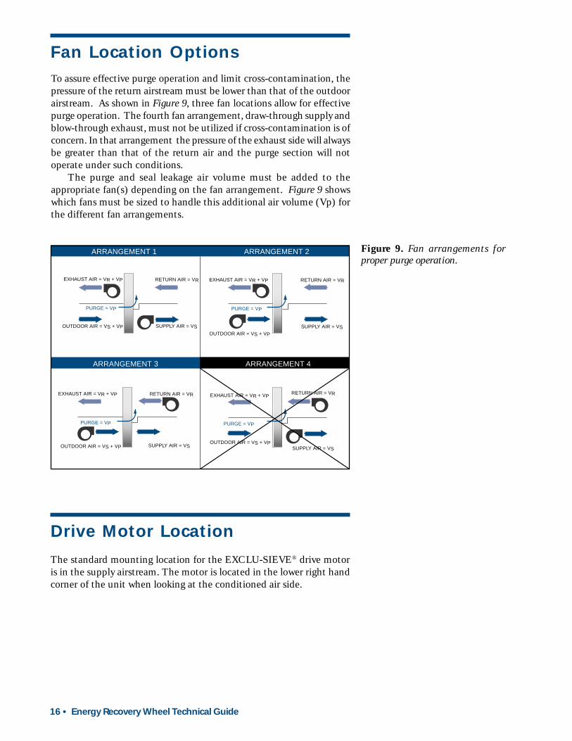
Fan Location OptionsTo assure effective purge operation and limit cross-contamination, thepressure of the return airstream must be lower than that of the outdoorairstream. As shown in Figure 9, three fan locations allow for effectivepurge operation. The fourth fan arrangement, draw-through supply andblow-through exhaust, must not be utilized if cross-contamination is ofconcern. In that arrangement the pressure of the exhaust side will alwaysbe greater than that of the return air and the purge section will notoperate under such conditions.
The purge and seal leakage air volume must be added to theappropriate fan(s) depending on the fan arrangement. Figure 9 showswhich fans must be sized to handle this additional air volume (Vp) forthe different fan arrangements.
Figure 9. Fan arrangements forproper purge operation.
The standard mounting location for the EXCLU-SIEVE® drive motoris in the supply airstream. The motor is located in the lower right handcorner of the unit when looking at the conditioned air side.
Drive Motor Location

Energy Recovery Wheel Technical Guide • 17
Filtration Requirements
The EXCLU-SIEVE® media is designed to induce laminar flow underall conditions. This results in a flow profile which causes airborneparticles smaller than approximately 800 microns, to pass freely throughthe rotor media (See Figure 10).
Self Cleaning FeatureAs the EXCLU-SIEVE® rotor operates between two opposing air streams,the continuous reversal of airflow results in a very efficient “self cleaning”process. This process is further enhanced by the very high velocity ofthe airflow in the purge section. As a result, only minimal filtration isrequired for efficient operation of the EXCLU-SIEVE® unit underconditions encountered most typically in commercial and institutionalbuildings.
Figure 10. Comparison of laminarand turbulent flow profiles in thetransfer media.
Outdoor and Supply AirstreamsAn insect screen should be placed behind the outdoor air intake louverin order to prohibit large items such as insects, leaves and debris fromentering the EXCLU-SIEVE® energy wheel. It is also recommendedthat low efficiency (20 - 30 percent), cleanable or pleated filters beprovided prior to the EXCLU-SIEVE® energy wheel.
Return AirstreamFor applications where the return air is relatively clean (such as generaloffice areas), no filtration is required prior to the EXCLU-SIEVE® energywheel. In industrial or institutional applications where the return aircontains bacteria, lint, oil mist, or animal hair, the appropriate filtrationmust be incorporated. Please contact SEMCO Incorporated for specificrecommendations.
LAMINAR FLOW: Particles pass through the flute at uniform velocity- Flow velocity is maximum in the center of the flute- Flow velocity is zero at the flute wall
TURBULENT FLOW: Particles pass through the flute at random velocities- Flow velocity is not uniform through the flute- Particles hit the flute wall and may collect on the wall
18 • Energy Recovery Wheel Technical Guide
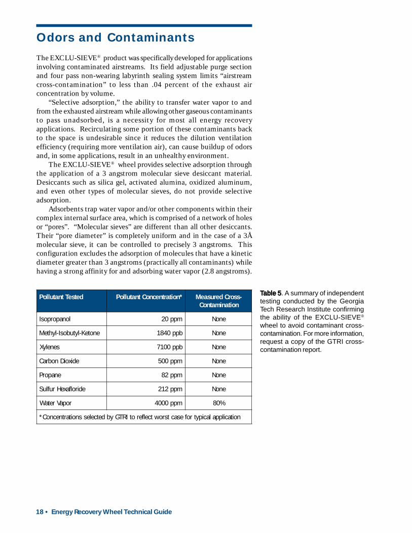
TTTTTable 5able 5able 5able 5able 5. A summary of independenttesting conducted by the GeorgiaTech Research Institute confirmingthe ability of the EXCLU-SIEVE®
wheel to avoid contaminant cross-contamination. For more information,request a copy of the GTRI cross-contamination report.
The EXCLU-SIEVE® product was specifically developed for applicationsinvolving contaminated airstreams. Its field adjustable purge sectionand four pass non-wearing labyrinth sealing system limits “airstreamcross-contamination” to less than .04 percent of the exhaust airconcentration by volume.
“Selective adsorption,” the ability to transfer water vapor to andfrom the exhausted airstream while allowing other gaseous contaminantsto pass unadsorbed, is a necessity for most all energy recoveryapplications. Recirculating some portion of these contaminants backto the space is undesirable since it reduces the dilution ventilationefficiency (requiring more ventilation air), can cause buildup of odorsand, in some applications, result in an unhealthy environment.
The EXCLU-SIEVE® wheel provides selective adsorption throughthe application of a 3 angstrom molecular sieve desiccant material.Desiccants such as silica gel, activated alumina, oxidized aluminum,and even other types of molecular sieves, do not provide selectiveadsorption.
Adsorbents trap water vapor and/or other components within theircomplex internal surface area, which is comprised of a network of holesor “pores”. “Molecular sieves” are different than all other desiccants.Their “pore diameter” is completely uniform and in the case of a 3Åmolecular sieve, it can be controlled to precisely 3 angstroms. Thisconfiguration excludes the adsorption of molecules that have a kineticdiameter greater than 3 angstroms (practically all contaminants) whilehaving a strong affinity for and adsorbing water vapor (2.8 angstroms).
detseTtnatulloP *noitartnecnoCtnatulloP -ssorCderusaeMnoitanimatnoC
lonaporposI mpp02 enoN
enoteK-lytubosI-lyhteM bpp0481 enoN
senelyX bpp0017 enoN
edixoiDnobraC mpp005 enoN
enaporP mpp28 enoN
edirolfaxeHrufluS mpp212 enoN
ropaVretaW mpp0004 %08
noitacilppalacipytrofesactsrowtcelferotIRTGybdetcelessnoitartnecnoC*
Odors and Contaminants
Energy Recovery Wheel Technical Guide • 19
Wheel Speed Control
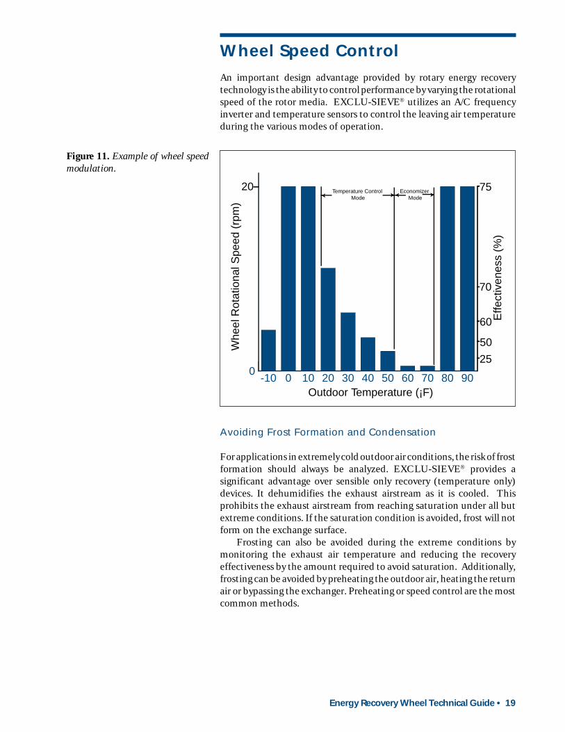
An important design advantage provided by rotary energy recoverytechnology is the ability to control performance by varying the rotationalspeed of the rotor media. EXCLU-SIEVE® utilizes an A/C frequencyinverter and temperature sensors to control the leaving air temperatureduring the various modes of operation.
Figure 11. Example of wheel speedmodulation.
Avoiding Frost Formation and Condensation
For applications in extremely cold outdoor air conditions, the risk of frostformation should always be analyzed. EXCLU-SIEVE® provides asignificant advantage over sensible only recovery (temperature only)devices. It dehumidifies the exhaust airstream as it is cooled. Thisprohibits the exhaust airstream from reaching saturation under all butextreme conditions. If the saturation condition is avoided, frost will notform on the exchange surface.
Frosting can also be avoided during the extreme conditions bymonitoring the exhaust air temperature and reducing the recoveryeffectiveness by the amount required to avoid saturation. Additionally,frosting can be avoided by preheating the outdoor air, heating the returnair or bypassing the exchanger. Preheating or speed control are the mostcommon methods.
0
10
20
30
40
50
60
70
80
9080706050403020100-10
Temperature Control Mode
Economizer Mode
Effe
ctiv
enes
s (%
)
75
70
60
50
25
20
Whe
el R
otat
iona
l Spe
ed (
rpm
)
Outdoor Temperature (¡F)
20 • Energy Recovery Wheel Technical Guide
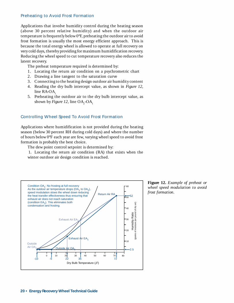
Preheating to Avoid Frost Formation
Applications that involve humidity control during the heating season(above 30 percent relative humidity) and when the outdoor airtemperature is frequently below 0°F, preheating the outdoor air to avoidfrost formation is usually the most energy efficient approach. This isbecause the total energy wheel is allowed to operate at full recovery onvery cold days, thereby providing for maximum humidification recovery.Reducing the wheel speed to cut temperature recovery also reduces thelatent recovery.
The preheat temperature required is determined by:1. Locating the return air condition on a psychrometric chart2. Drawing a line tangent to the saturation curve3. Connecting to the heating design outdoor air humidity content4. Reading the dry bulb intercept value, as shown in Figure 12,
line RA-OA15. Preheating the outdoor air to the dry bulb intercept value, as
shown by Figure 12, line OA2-OA1
Controlling Wheel Speed To Avoid Frost Formation
Applications where humidification is not provided during the heatingseason (below 30 percent RH during cold days) and where the numberof hours below 0°F each year are few, varying wheel speed to avoid frostformation is probably the best choice.
The dew point control setpoint is determined by:1. Locating the return air condition (RA) that exists when thewinter outdoor air design condition is reached.
Figure 12. Example of preheat orwheel speed modulation to avoidfrost formation.
605040 8070
40
30
20
Dry Bulb Temperature (¡F)
60
3020100
10
50Return Air RA
Outside Air OA1
OutsideAir OA2
Exhaust Air EA1
Exhaust Air EA2
Condition OA1: No frosting at full recoveryAs the outdoor air temperature drops (OA1 to OA2),speed modulation slows the wheel down reducingthe heat transfer effectiveness thus ensuring thatexhaust air does not reach saturation (condition EA2). This eliminates bothcondensation and frosting.
-5 22-10 35 72
2.5
52
Hum
idity
Rat
io
(gra
ins
of m
oist
ure
per
poun
d of
dry
air)
Energy Recovery Wheel Technical Guide • 21
2. Plot the RA point on the psychrometric chart and draw a linebetween it and the winter design point.
3. Determine the higher dry bulb temperature at which this lineintercepts the saturation curve (EA2 on Figure 12).
4. Add 2°F to this temperature and this becomes the control (winter)setpoint.
Avoiding Overheating (Economizer Cycle)
During the Spring and Fall seasons, when the outdoor air temperatureis close to that being supplied to the space, the EXCLU-SIEVE® controlsystem will slow the media rotational speed in response to a supply air setpoint. This decreases the recovery effectiveness by the amout requiredto provide the desired supply air temperature (See Figure 11).
Automatic Summer-Winter Change Over
By monitoring the difference between the outdoor air condition and thereturn air condition, the cooling mode is selected whenever the outdoorair is warmer than the return air. This calls for full recovery effectivenessonce again. Full recovery is maintained automatically until the outdoorair condition drops to the point where the economizer cycle is mostefficient.
Condensation on Sensible Only Wheels
Variable wheel speed and reheat approaches can be used for sensibleenergy wheels. Consult SEMCO Incorporated for assistance.
22 • Energy Recovery Wheel Technical Guide
Sensible Wheel Performance
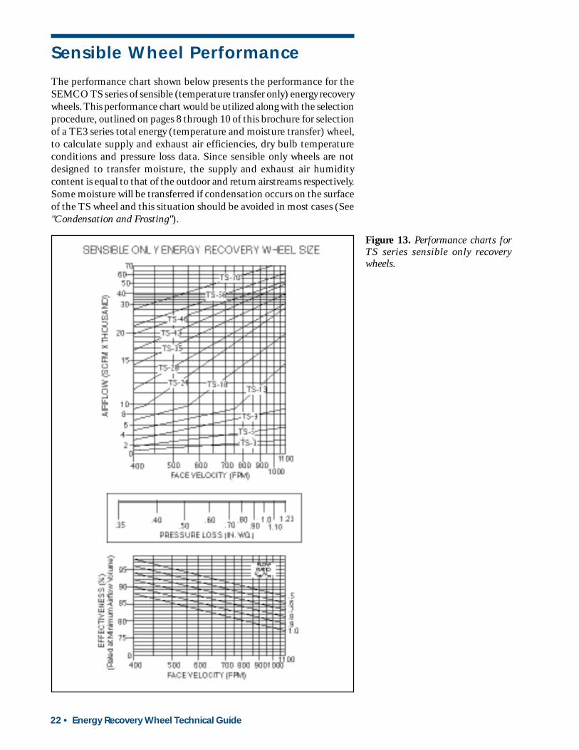
The performance chart shown below presents the performance for theSEMCO TS series of sensible (temperature transfer only) energy recoverywheels. This performance chart would be utilized along with the selectionprocedure, outlined on pages 8 through 10 of this brochure for selectionof a TE3 series total energy (temperature and moisture transfer) wheel,to calculate supply and exhaust air efficiencies, dry bulb temperatureconditions and pressure loss data. Since sensible only wheels are notdesigned to transfer moisture, the supply and exhaust air humiditycontent is equal to that of the outdoor and return airstreams respectively.Some moisture will be transferred if condensation occurs on the surfaceof the TS wheel and this situation should be avoided in most cases (See"Condensation and Frosting").
Figure 13. Performance charts forTS series sensible only recoverywheels.

Energy Recovery Wheel Technical Guide • 23
Sensible Wheel Applications
Sensible wheels should only be applied to applications where the transferof moisture is undesirable. This is due to the fact that the EXCLU-SIEVE® total energy wheel is approximately the same cost, but offersthe advantage of latent recovery and the associated frost controladvantage, which makes it the product of choice for even heating modeonly applications.
Examples of sensible only applications include indirect evaporativecooling, direct/indirect evaporative cooling, desiccant based cooling(second wheel) and in the reheat position in the SEMCO EPD systemconcept.
The common element for all of these applications is the importanceof avoiding any moisture transfer. To avoid moisture transfer, it is criticalthat the aluminum wheel media be carefully coated to avoid the inherentoxidation that would otherwise take place over time, turning a sensiblewheel into a moderately effective latent wheel. As a result, all SEMCOTS sensible only wheels are made from a polymer coated aluminumsubstrate, which is carefully coated prior to being formed into thehoneycomb transfer media.
Unlike the EXCLU-SIEVE® total energy wheel where the supply airleaving the wheel follows a straight path between the return air and theoutdoor air, a plot of the supply air condition leaving a sensible onlywheel on a psychrometric chart resembles that of a chilled water coil.Since no moisture is transferred by a sensible wheel, the temperature ofthe air streams are changed as the sensible energy is exchanged, but themoisture level remains constant unless the supply air or exhaustairstreams are cooled to below their dew points.
If this occurs, one of three things will happen:1. If the exhaust airstream is cooled to less than approximately 20°F
below its dew point, and if the leaving temperature of the airstreamis above 32°F, a thin film of condensate will form on the vast surfacesof the wheel media, and this condensate will re-evaporate into thewarmed supply airstream. If this moisture transfer is a problem, itcan best be avoided by limiting the exhaust side recovery withcontrols to vary wheel speed based on a dew point temperature sensor.
2. If the exhaust airstream is cooled more than 20°F below its dewpoint, and if the leaving temperature of the airstream is above 32°F,some condensate will re-evaporate into the warmed supply airstreamand the remainder will blow off of the wheel surface. This is notadvised and, as a result, the variable wheel speed controller shouldonce again be applied.
3. If the exhaust airstream is cooled below 32°F and reaches its dewpoint, frost may form on the face of the wheel, reducing airflow.Preheat should be applied in this case to avoid cooling the exhaustairstream below its dew point.
Condensation & Frosting

24 • Energy Recovery Wheel Technical Guide
Cleaning The Wheel Media
The SEMCO EXCLU-SIEVE® energy recovery wheel has been designedso that a laminar flow is maintained within the transfer media at alloperating conditions. This means that the air and all other particles inthe airstream pass straight through the wheel.
Due to the laminar flow profile through the EXCLU-SIEVE® energywheel, any collection of dust or particulate matter will occur at theentering and leaving edges of the transfer media. Such buildup canusually be vacuumed, purged with compressed air or wiped from therotor surface. In rare cases where a more thorough cleaning is required,low temperature steam or hot water and detergent may be used. ConsultSEMCO for instructions when using cleaning methods other thancompressed air or vacuuming.
Provisions should be made to allow access to all four sides of themodule to facilitate seal adjustment and routine inspection.
Locate the A/C inverter control panel in a dry, conditioned spacewhich is clearly visible to the operations personnel. A rotation detectorshould be included as a part of the control package for all criticalapplications.
The purge section must always face the conditioned air side of thesystem. Rotation is such that a spot on the media in the return airsection would rotate towards the purge section without first passinginto the supply section.
Carefully review the purge, fan location and filter recommendationscovered by this brochure prior to completing any design. Select theappropriate control option for the application. Please consult SEMCOfor any additional design assistance required.
Consult SEMCO for design recommendations with applicationsinvolving hazardous contaminants, exhaust air temperatures in excessof 180°F and/or high humidity conditions (drying ovens, swimming pools,etc.).
Installation Guidelines

Energy Recovery Wheel Technical Guide • 25
Typical Wiring Schematic
INVERTER MODEL POWER MAX. REC. ACINPUT LINE FUSE
VFS7S-2004UP* 200-230/1/60 15 AMPVFS7S-2007UP** 200-230/1/60 20 AMPVFS7S-4007UP*** 380-460/3/60 10 AMP
* THROUGH WHEEL SIZE 24** WHEEL SIZE 28 AND LARGER*** ALL SIZES⊗ Shipped loose for field mounting
200-230V, 50/60Hz, 1ph in /3ph out380-460V, 50/60Hz, 3ph
REQUIRED BRANCH CIRCUIT PROTECTIONBY OTHERS
MOTOR
’S’ LEG USEDON 3ph ONLY
T U V W ESRPO
PA
PB
PP
CC
FM
P24
CRF =
VIA
VIB
OU
T1
OU
T2
RS
T
S1
S2
FL
A
FLB
GLC
TOSHIBA S7 VFD ⊗
DRY CONTACT CLOSURE BETWEEN TERMINALS F & CC FOR REMOTE START/STOP. FOR LOCAL S/S, SET cNOD=1
24V, 50/60Hz
NE
UT
RA
L
HO
T
B1-SUPPLY TEMP ⊗
B2-SPACE TEMP ⊗M
M⊗ B4-OUTDOOR TEMP
⊗ B3-EXHAUST TEMPM
M
ENERGY RECOVERY
WHEEL
M B1
B2
E1
E2 M B3
B4 M B5 M Y1
Y2
Y3
G0 G G
RWX62.7036 ⊗
Q11
14 12 Q21
24 Q31
34 32 Q41
44 Q51
54 Q61
64
ROTATION DETECTOR SENSOR1 1 2 2 3 4 5 N
24V, 50/60Hz
TERMINALS PROVIDING DRYCONTACT CLOSURE FORREMOTE ALARM OUTPUT
ROTATION DETECTOR TERMINAL STRIP ⊗
INPUT POWER
M IS INTERNALLYCONNECTED COMMON
PUSH-BUTTONRESET SWITCH
PROXIMITY SENSOR - Mounted on bracket near wheel
102b
104a
11
14
5(+)1(-)
CR-1
103103
107
1 1
1
2 2
2
3
3
4
4
5
5 6
78
N
TRU-1 N
R
1k OHM RESISTOR
FAULTINDICATORLIGHT
MOUNTED IN ENCLOSURE PANEL DOOR
103
DRY CONTACT CONNECTIONS FORREMOTE ALARMOUTPUT.
+ _
N
107
* PROXIMITY SENSOR REQUIRES 20ga GALV. TARGET WITH PROPER LENGTH FOR THE WHEEL DIAMETER.
108
109
101a
101b
102a
102b
104b
105
104a
106
101
24V POWER
TIMERRELAY BASE
104b101b
105 UNIVERSAL TIME DELAY RELAY
1 100TIME ADJUSTMENT
SEC MIN.
SELECTONE RANGE
x0.1x1x10
INPUTPOWER
OUTPUTRELAY
RECYCLEINTERVALDELAY ON MAKE
NOT USED
101a
102a
NOTES:* 120/24V TRANSFORMER AVAILABLE AS OPTION* TIMER RELAY SET AT 30 MINUTES*AN ENCLOSURE IS PROVIDED FOR STAND ALONE SYSTEMS. FOR UNITS WITH BOTH RWX AND ROTATION DETECTOR, A 12X12 ENCLOSURE ISPROVIDED. FOR UNITS WITH EITHER AN RWX OR ROTATION DETECTOR, AN 8X8 ENCLOSURE IS PROVIDED.
TIMER RELAYTRU-1
TIMER SETTINGS
Field WiringFactory Wiring

26 • Energy Recovery Wheel Technical Guide
Mounting ArrangementsThe EXCLU-SIEVE® units can be mounted in six different positions(see Figure 14). The number of support points required for horizontalmounting may vary depending on the size of the unit. Consult SEMCOfor support details.
When installing an EXCLU-SIEVE® unit, the purge section mustalways face the conditioned air side of the system. Rotation is such thata spot on the media in the return air section would rotate towards thepurge section without first passing into the supply section.
There are three different control options that can be ordered with theTotal Energy Recovery unit:
No Controls:Power is connected directly to the motor. The wheel rotates at a
constant speed (20 rpm).
Variable Frequency Drive (VFD) ONLY:SEMCO ships a pre-qualified variable frequency drive with the unit
for field mounting. The VFD has the same voltage as the motor andcan modulate the motor from 20 rpm to 1/4 rpm. Four temperaturesensors (one in each air stream), and a PCM must be field provided,mounted, wired and programmed.
Wheel Drive Options
Figure 14. Wheel mountingarrangements.
RA SA
Arrangement A
Arrangement B
Arrangement C
RASA
RA
SA
Arrangement D
RA
SA
Arrangement E
SA
RA
Arrangement F
OA
SA
EA
RA: Return AirSA: Supply Air
OA: Outside AirEA: Exhaust Air
Energy Recovery Wheel Technical Guide • 27
Ordering Key
Variable Frequency Drive (VFD) & Controls:SEMCO ships the same variable frequency drive mentioned above,
along with four temperature sensors and a solid state controller withthe module. All of these accessories are to be field mounted and wired.The advantage of this option is that it is a pre-packaged stand alonesystem.
A rotation detector can be ordered with any of the control optionsmentioned above. This rotation detector will ship with the unit forfield mounting.
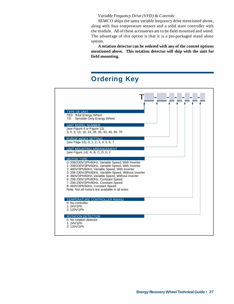
TYPE OF UNITTE3: Total Energy WheelTS: Sensible Only Energy Wheel
UNIT MODEL NUMBER(see Figure 4 or Figure 13):3, 5, 9, 13, 18, 24, 28, 35, 43, 46, 56, 70
PURGE INDEX SETTING(see Page 15): 0, 1, 2, 3, 4, 5, 6, 7
UNIT MOUNTING ARRANGEMENT(see Figure 14): A, B, C, D, E, F
MOTOR TYPE0: 208/230V/1Ph/60Hz, Variable Speed, With Inverter1: 208/230V/3Ph/60Hz, Variable Speed, With Inverter2: 460V/3Ph/60Hz, Variable Speed, With Inverter3: 208-230V/3Ph/60Hz, Variable Speed, Without Inverter4: 460V/3Ph/60Hz, Variable Speed, Without Inverter6: 208-230V/1Ph/60Hz, Constant Speed7: 208-230V/3Ph/60Hz, Constant Speed8: 460V/3Ph/60Hz, Constant SpeedNote: Not all motors are available in all sizes
TEMPERATURE CONTROLLER RWX620: No controller1: 24V/1Ph2: 120V/1Ph
ROTATION DETECTOR0: No rotation detector1: 24V/1Ph2: 120V/1Ph
T__-__-_-_-_-_-_
28 • Energy Recovery Wheel Technical Guide
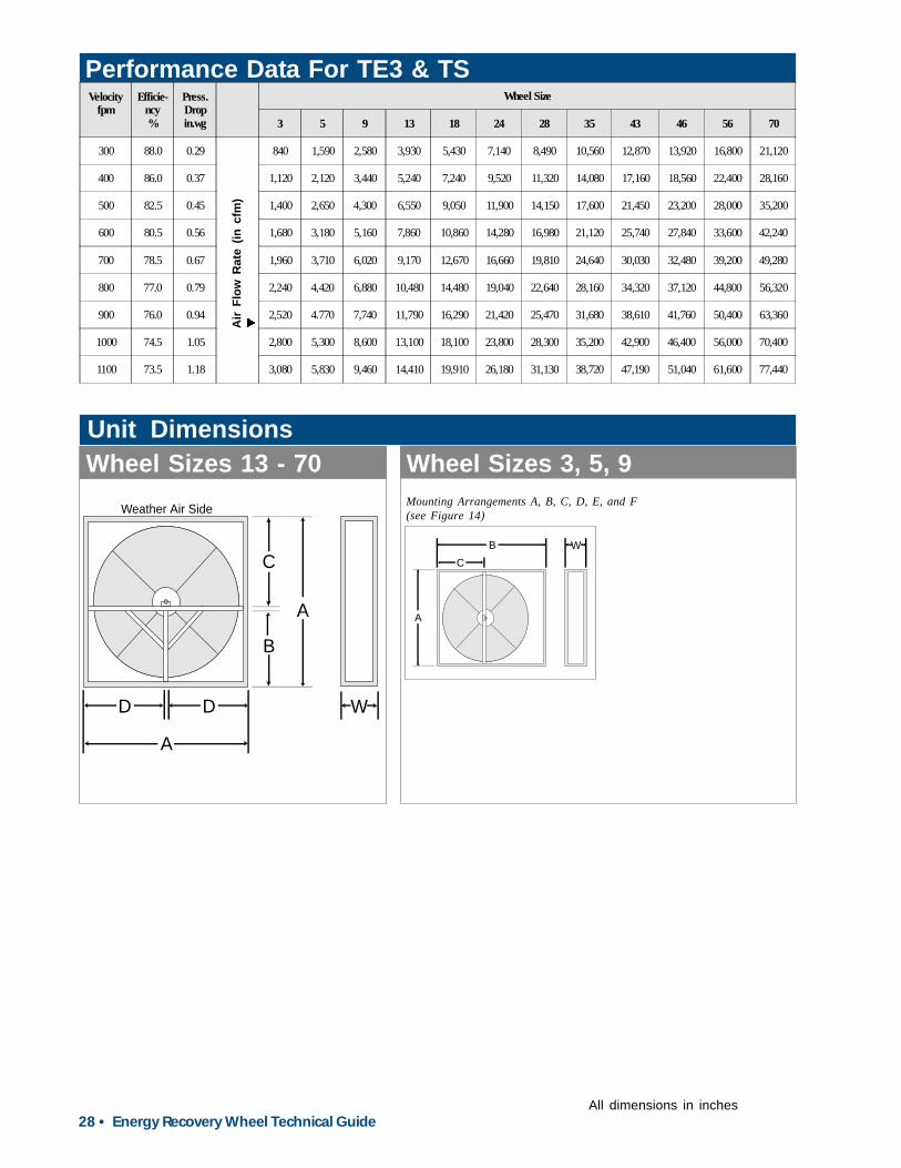
Performance Data For TE3 & TSWheels
C
A
B
A
D D
Weather Air Side
W
Unit DimensionsWheel Sizes 13 - 70 Wheel Sizes 3, 5, 9
Mounting Arrangements A, B, C, D, E, and F(see Figure 14)
Air
Flow
Rat
e (in
cfm
)t
All dimensions in inches
A
C
B W
Velocityfpm
Efficie-ncy%
Press.Dropin.wg
Wheel Size
3 5 9 13 18 24 28 35 43 46 56 70
300 88.0 0.29 840 1,590 2,580 3,930 5,430 7,140 8,490 10,560 12,870 13,920 16,800 21,120
400 86.0 0.37 1,120 2,120 3,440 5,240 7,240 9,520 11,320 14,080 17,160 18,560 22,400 28,160
500 82.5 0.45 1,400 2,650 4,300 6,550 9,050 11,900 14,150 17,600 21,450 23,200 28,000 35,200
600 80.5 0.56 1,680 3,180 5,160 7,860 10,860 14,280 16,980 21,120 25,740 27,840 33,600 42,240
700 78.5 0.67 1,960 3,710 6,020 9,170 12,670 16,660 19,810 24,640 30,030 32,480 39,200 49,280
800 77.0 0.79 2,240 4,420 6,880 10,480 14,480 19,040 22,640 28,160 34,320 37,120 44,800 56,320
900 76.0 0.94 2,520 4.770 7,740 11,790 16,290 21,420 25,470 31,680 38,610 41,760 50,400 63,360
1000 74.5 1.05 2,800 5,300 8,600 13,100 18,100 23,800 28,300 35,200 42,900 46,400 56,000 70,400
1100 73.5 1.18 3,080 5,830 9,460 14,410 19,910 26,180 31,130 38,720 47,190 51,040 61,600 77,440
Energy Recovery Wheel Technical Guide • 29
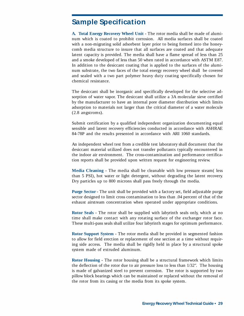
Sample Specification
A. Total Energy Recovery Wheel Unit - The rotor media shall be made of alumi-num which is coated to prohibit corrosion. All media surfaces shall be coatedwith a non-migrating solid adsorbent layer prior to being formed into the honey-comb media structure to insure that all surfaces are coated and that adequatelatent capacity is provided. The media shall have a flame spread of less than 25and a smoke developed of less than 50 when rated in accordance with ASTM E87.In addition to the desiccant coating that is applied to the surfaces of the alumi-num substrate, the two faces of the total energy recovery wheel shall be coveredand sealed with a two part polymer heavy duty coating specifically chosen forchemical resistance.
The desiccant shall be inorganic and specifically developed for the selective ad-sorption of water vapor. The desiccant shall utilize a 3A molecular sieve certifiedby the manufacturer to have an internal pore diameter distribution which limitsadsorption to materials not larger than the critical diameter of a water molecule(2.8 angstroms).
Submit certification by a qualified independent organization documenting equalsensible and latent recovery efficiencies conducted in accordance with ASHRAE84-78P and the results presented in accordance with ARI 1060 standards.
An independent wheel test from a credible test laboratory shall document that thedesiccant material utilized does not transfer pollutants typically encountered inthe indoor air environment. The cross-contamination and performance certifica-tion reports shall be provided upon written request for engineering review.
Media Cleaning - The media shall be cleanable with low pressure steam( lessthan 5 PSI), hot water or light detergent, without degrading the latent recovery.Dry particles up to 800 microns shall pass freely through the media.
Purge Sector - The unit shall be provided with a factory set, field adjustable purgesector designed to limit cross contamination to less than .04 percent of that of theexhaust airstream concentration when operated under appropriate conditions.
Rotor Seals - The rotor shall be supplied with labyrinth seals only, which at notime shall make contact with any rotating surface of the exchanger rotor face.These multi-pass seals shall utilize four labyrinth stages for optimum performance.
Rotor Support System - The rotor media shall be provided in segmented fashionto allow for field erection or replacement of one section at a time without requir-ing side access. The media shall be rigidly held in place by a structural spokesystem made of extruded aluminum.
Rotor Housing - The rotor housing shall be a structural framework which limitsthe deflection of the rotor due to air pressure loss to less than 1/32". The housingis made of galvanized steel to prevent corrosion. The rotor is supported by twopillow block bearings which can be maintained or replaced without the removal ofthe rotor from its casing or the media from its spoke system.
30 • Energy Recovery Wheel Technical Guide
How to Reach SEMCO
You can reach SEMCO Incorporated by phone, fax, mail, or e-mail.
SEMCO IncorporatedDWP Service1800 East Pointe DriveColumbia, MO 65201-3508
888-4SEMCOINC (888-473-6264)573-443-1481Fax: 573-886-5408e-mail: [email protected]
For information about SEMCO Incorporated, our air quality productsand services, please point your web browser to www.semcoinc.com. There,you will also find the latest news from SEMCO and examples of howSEMCO’s energy recovery systems are being applied on a daily basis ina multitude of applications.
Optional Temperature Control Panel - Variable speed control shall be accom-plished by the use of an A/C inverter. The inverter shall include all digital pro-gramming with a manual speed adjustment on the front of the inverter. Thedrive system shall allow for a turndown ratio of 80:1 (20 rpm to 1/4 rpm). Thecontrol system shall include four linearized thermistor sensors as follows: (1)Proportional temperature controller mounted in the supply airstream. (2) dif-ferential summer/winter changeover sensors mounted in the outdoor and returnairstreams. (3) Frost prevention sensor located in the exhaust airstream. (4)Digital readout of the temperature readings recorded by these sensors and con-trol setpoints is displayed by the control panel.
Digital Performance Display Module - Digital read out confirming the effective-ness of the energy wheel via temperature readings recorded by these sensors andcontrol set points shall be displayed by the control panel.
B. Warranty - The unit manufacturer shall warrant to the Buyer that for a periodof eighteen months from the date of shipment the goods to be delivered to theBuyer shall in all material respects be free from defects in material and workman-ship when used in a proper and normal manner. Should any failure to conform tothe above appear within eighteen months after the date of shipment, the unitmanufacturer shall upon prompt notification thereof during the Warranty Periodand confirmation to the unit manufacturer’s satisfaction that the goods havebeen stored, installed, operated and maintained properly and in accordance withstandard industry practice, correct the non-conformity at the unit manufacturer’soption either by repairing any defective part or parts or by making available at theunit manufacturer’s plant a repaired or replacement part.

Energy Recovery Wheel Technical Guide • 31
TYPE OF UNITTE3: Total Energy WheelTS: Sensible Only Energy Wheel
UNIT MODEL NUMBER3, 5, 9, 13, 18, 24, 28, 35, 43, 46, 56, 70
PURGE ANGLE0, 1, 2, 3, 4, 5, 6, 7, 8, 9, 10
UNIT MOUNTING ARRANGEMENTA, B, C, D, E, F
MOTOR TYPE0: 208/230V/1Ph/60Hz, Variable Speed, With Inverter1: 208/230V/3Ph/60Hz, Variable Speed, With Inverter2: 460V/3Ph/60Hz, Variable Speed, With Inverter3: 208-230V/3Ph/60Hz, Variable Speed, Without Inverter4: 460V/3Ph/60Hz, Variable Speed, Without Inverter6: 208-230V/1Ph/60Hz, Constant Speed7: 208-230V/3Ph/60Hz, Constant Speed8: 460V/3Ph/60Hz, Constant SpeedNote: Not all motors are available in all sizes
TEMPERATURE CONTROLLER RWX620: No controller1: 24V/1Ph2: 120V/1Ph
ROTATION DETECTOR0: No rotation detector1: 24V/1Ph2: 120V/1Ph
T__-__-_-_-_-_-_
Desiccant Wheel Products
JOB NAME
WheelConfigurationChecklist
RA: Return AirSA: Supply AirOA: Outside AirEA: Exhaust Air
UNIT TAG DATEWHEELWHEELWHEELWHEELWHEEL
ARRANGEMENTSARRANGEMENTSARRANGEMENTSARRANGEMENTSARRANGEMENTSArrangement A
RA SA
Arrangement C
RA
SA
Arrangement D
RA
SA
Arrangement E
SA
RA
SA
Arrangement F
OA
EA
Arrangement B
RASA
Hold for Approval Release for Production
Please check one:
Signature

W AB 005.4 0702 (supersedes W AB 005.3 0301)0702 1K B
1800 East Pointe DriveColumbia, Missouri 65201-35081-888-4SEMCOINC (1-888-473-6264)573-443-1481Fax: 573-886-5408E-mail: [email protected]
wwwwwwwwwwwwwww.semcoinc.com.semcoinc.com.semcoinc.com.semcoinc.com.semcoinc.com
Certified, Specified, Proven™


