An Introduction to An Introduction to Digital Systems Digital Systems Simulation Simulation Paolo PRINETTO Politecnico di Torino (Italy) University of Illinois at Chicago, IL (USA) [email protected][email protected]www.testgroup.polito.it Lecture 10.1
Transcript
An Introduction to An Introduction to Digital Systems Digital Systems
SimulationSimulation
An Introduction to An Introduction to Digital Systems Digital Systems
pattern i 00 01 10 11pattern i 00 01 10 11pattern i < file1.patpattern i < file1.patwfm a @0=1 @10=0 10=1 15=0 @50=1wfm a @0=1 @10=0 10=1 15=0 @50=1wfm a @0=0 @100=1 (200=0 200=1)*2wfm a @0=0 @100=1 (200=0 200=1)*2wfm a @0=00\H (1000 = inc by 1\D)*4wfm a @0=00\H (1000 = inc by 1\D)*4
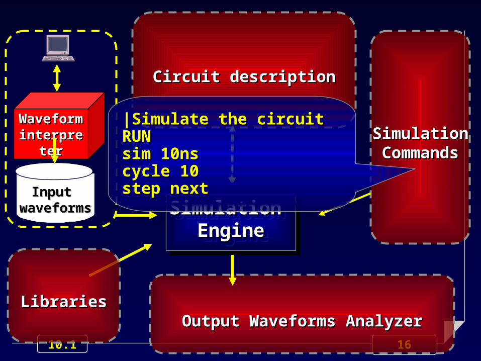
Using a simulation tool for Validation & Verification
23 10.1
Be careful:Be careful:Exhaustive Exhaustive Simulation Simulation
is mostly unfeasibleis mostly unfeasible
24 10.1
Just an example...
Exhaustively simulating a 32 bit adder requires applying
265 input values
Assuming simulating a single value require 1 ns, the whole simulation process would requires 1,100+ years !!!!
25 10.1
A further example...
CPU Intel 8080:
about 120 latches
256 machine instructions
8-bit and 16-bit operands:
3.15 1045 instructions
26 10.1
A further example...
CPU Intel 8080:
about 120 latches
256 machine instructions
8-bit and 16-bit operands:
3.15 1045 instructions
1032 years
The life of our Universe is estimated 2 2 ·· 10 101010 years !
27 10.1
A basic approach to V&V
Identify the set of peculiar aspects, or properties, of the design that need to be checked
28 10.1
A basic approach to V&V
Identify the set of peculiar aspects, or properties, of the design that need to be checked
Organize your V&V operations as a set of independent sessions, each aiming at checking the correctness of some of the above selected peculiar aspects or properties.
29 10.1
A simulation session
For each target aspect or property:
State how to check it
Select the minimum set of input values needed
For each selected value, state the expected output
Identify the most efficient way for:
applying the input values
analyzing the circuit behavior.
30 10.1
A simulation session (cont’d)
Hints:
Simulate the basic behaviors of the system, first
Then, focus on potential critical situations:
Identify border line conditions between alternative behaviors (e.g., change the status of the circuit)
Force the circuit to reach border line conditions
31 10.1
Identify the most efficient way to perform simulation
experiments
A simulation experiment can be performed in either way:
resorting to a VHDL Test Bench (highly recommended)
controlling the experiment manually, in a highly interactive manner (for expert designers or for fine tuning and debugging).
32 10.1
The basic principle
VHDL VHDL Description Description of the target of the target
systemsystem
33 10.1
The basic principle
VHDL VHDL Description Description of the target of the target
systemsystem
Test Bench
34 10.1
The basic principle
VHDL VHDL Description Description of the target of the target
systemsystem
Test Bench
35 10.1
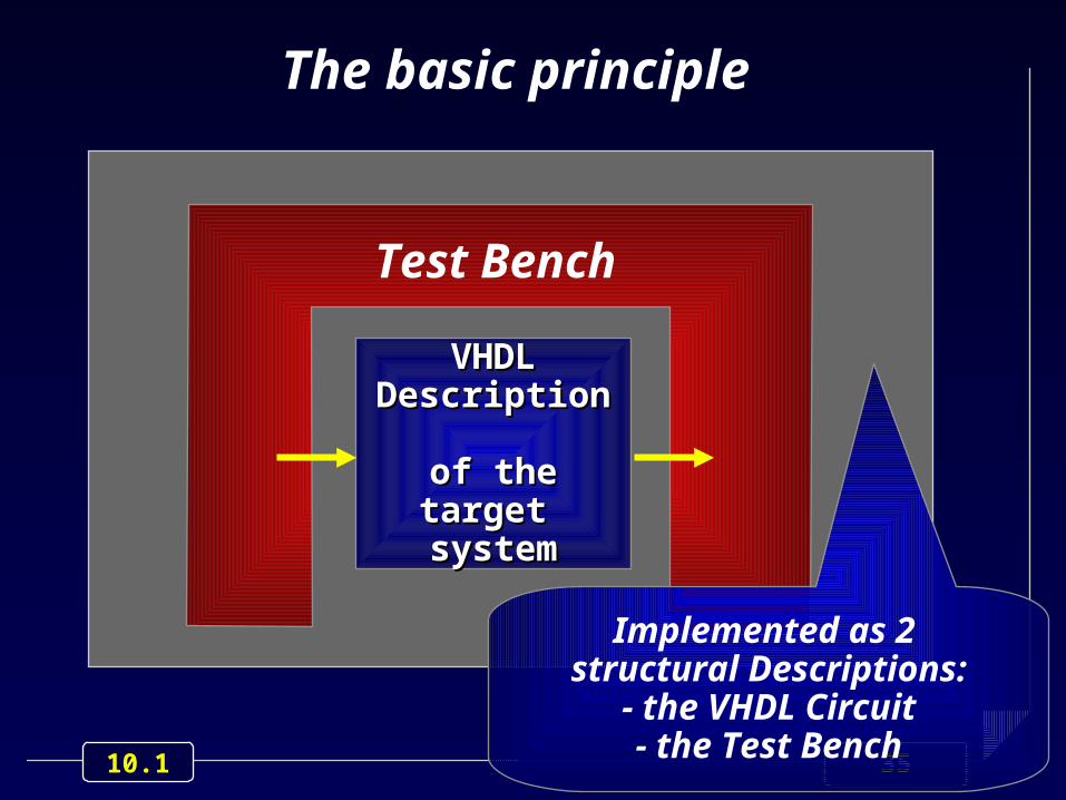
The basic principle
VHDL VHDL Description Description of the target of the target
systemsystem
Test Bench
Implemented as 2 structural Descriptions:
- the VHDL Circuit- the Test Bench
36 10.1
The basic principle
VHDL VHDL Description Description of the target of the target
systemsystem
Test Bench
The entity of the target circuit must be the actual one
37 10.1
Test Bench characteristics
The same Test Bench should be used though the overall design process, from specs to netlist
38 10.1
Test Bench characteristics(cont’d)
The Test Bench is described for simulation purposes, only, and therefore it does not have to be synthesizable
It may thus contains not-synthesizable statements, such as:
timing specification (e.g., wait) to generate the input waveforms
assertions to check the output waveforms and to generate error messages.
39 10.1
Test Bench characteristics(cont’d)
The Test Bench can have different complexities, to perform different tasks during the various V&V steps:
just apply input values:
generated internally
read from external files
apply input values & check output values
save output values on external files
...
40 10.1
Some examples
We shall consider some cases.
41 10.1
Case #1
The input values are explicitly specified within the Test Bench process
The correctness of the output values is evaluated analyzing the displayed output waveforms, using the facilities of the simulation tools.
42 10.1
Case #2
The input values and the corresponding expected outputs are stored inside the Test Bench, resorting to an array
The Test Bench process reads from the array the input values, and applies them to the target system
The correctness of the output values is evaluated inside the Test Bench process. Using an assert statement, the output values of the target circuit are compared with the expected ones, stored into the array.
43 10.1
Case #3
The input values and the corresponding expected outputs are stored into two distinct files
First, the Test Bench process reads, from an input file, the input values and applies them to the target system
Then, the Test Bench process writes, on an output file, the output values generated by the target circuit
44 10.1
Case #3 (cont’d)
The correctness of the output values is evaluated externally to the Test Bench process: the generated output file is compared with a file of expected output values, defined by the designer.
45 10.1
Case #3: typical usage
The proposed approach is typically used for both design validation and verification.