ORDINANCE NO. _________________ AN ORDINANCE REPEALING AND REPLACING ARTICLE 12 OF CITY CODE CHAPTER 25- 12 TO ADOPT ASHRAE 90.1-2013 AND THE 2015 INTERNATIONAL ENERGY CONSERVATION CODE AND LOCAL AMENDMENTS. BE IT ORDAINED BY THE CITY COUNCIL OF THE CITY OF AUSTIN: PART 1. City Code Chapter 25-12 (Technical Codes) is amended to repeal Article 12 (Energy Code) and replace it with a new Article 12 to read as follows: ARTICLE 12. - ENERGY CODE. § 25-12-261 - ENERGY CODE. (A) The International Energy Conservation Code, 2015 Edition (2015 International Energy Conservation Code), published by the International Code Council, Inc., is adopted and incorporated by reference into this section with the deletions and amendments in Subsections (B) and (C) and Section 25-12-263 (Local Amendments to the Energy Code). (B) The following commercial provisions of the 2015 International Energy Conservation Code are deleted. A subsection contained within a deleted section or subsection is not deleted, unless specifically listed below. C201.3 C202 definition of “Registered Design Professional” C402.3 C402.4.3 C405.2 C408.2 C408.2.1 C408.2.2 C408.2.2.1 C408.2.2.2 C408.2.3 C408.2.3.1 C408.2.3.2 C408.2.3.3 C408.2.4 C408.2.4.1 C408.2.4.2 C408.2.5 C408.2.5.1 C408.2.5.2 C408.2.5.3 C408.2.5.4 (C) For purposes of commercial energy efficiency compliance with ASHRAE standards, as allowed under the 2015 International Energy Conservation Code, the following provisions of the 2013 edition of ASHRAE standard 90.1 (ASHRAE 90.1-2013), published by the American Society of Heating, Refrigeration, and Air- Conditioning Engineers, are deleted. A subsection contained within a deleted section or subsection is not deleted, unless specifically listed below. 3.2 definition of “design professional” 5.5.3.1.1 5.5.4.1 5.5.4.4.1 Table 5.5.4.4.1 6.5.10 6.7.2.4 8.4.2 9.4.1 G1.1 G2.4.2 (D) The following residential provisions of the 2015 International Energy Conservation Code are deleted. A subsection contained within a deleted section or subsection is not deleted, unless specifically listed below. R202 definition of “Residential Building” R402.1.2 Table R402.1.2 Table R402.1.4 R402.4.4 R402.5 R403.3.1 R403.3.2 R403.3.3 R403.3.4 R403.9 R404.1 R405.2 R405.3 Table R405.5.2(1) R406.2 R406.3 Table R406.4
Transcript
ORDINANCE NO. _________________ AN ORDINANCE REPEALING AND REPLACING ARTICLE 12 OF CITY CODE CHAPTER 25-12 TO ADOPT ASHRAE 90.1-2013 AND THE 2015 INTERNATIONAL ENERGY CONSERVATION CODE AND LOCAL AMENDMENTS.
BE IT ORDAINED BY THE CITY COUNCIL OF THE CITY OF AUSTIN:
PART 1. City Code Chapter 25-12 (Technical Codes) is amended to repeal Article 12 (Energy Code) and replace it with a new Article 12 to read as follows:
ARTICLE 12. - ENERGY CODE. § 25-12-261 - ENERGY CODE. (A) The International Energy Conservation Code, 2015 Edition (2015 International Energy Conservation Code),
published by the International Code Council, Inc., is adopted and incorporated by reference into this section with the deletions and amendments in Subsections (B) and (C) and Section 25-12-263 (Local Amendments to the Energy Code).
(B) The following commercial provisions of the 2015 International Energy Conservation Code are deleted. A subsection contained within a deleted section or subsection is not deleted, unless specifically listed below.
(C) For purposes of commercial energy efficiency compliance with ASHRAE standards, as allowed under the
2015 International Energy Conservation Code, the following provisions of the 2013 edition of ASHRAE standard 90.1 (ASHRAE 90.1-2013), published by the American Society of Heating, Refrigeration, and Air-Conditioning Engineers, are deleted. A subsection contained within a deleted section or subsection is not deleted, unless specifically listed below.
3.2 definition of “design professional” 5.5.3.1.1 5.5.4.1
5.5.4.4.1 Table 5.5.4.4.1 6.5.10 6.7.2.4
8.4.2 9.4.1 G1.1 G2.4.2
(D) The following residential provisions of the 2015 International Energy Conservation Code are deleted. A
subsection contained within a deleted section or subsection is not deleted, unless specifically listed below.
§25-12-262 CITATIONS TO THE ENERGY CODE In the City Code, “Energy Code” means the 2015 International Energy Conservation Code adopted by section 25-12-261, as amended, including local amendments adopted by section 25-12-263. §25-12-263 LOCAL AMENDMENTS TO THE ENERGY CODE (A) The following provisions are local amendments to the commercial provisions of the 2015 International
Energy Conservation Code. Each provision in this subsection is a substitute for an identically numbered provision deleted by Section 25-12-261(B) or an addition to the Energy Code.
Section C201.3 Terms defined in other codes. Terms not defined in this Code that are defined in the Building Code, Electrical Code, Fire Code, Mechanical Code, the Plumbing Code, Residential Code or the Solar Code have the meaning ascribed to them in those codes.
SECTION C202 GENERAL DEFINITIONS - REGISTERED DESIGN PROFESSIONAL. An individual who is registered or licensed to practice their respective design profession as defined by the statutory requirements of the professional registration laws of the state or jurisdiction in which the project is to be constructed.
For the purposes of Section C408, System Commissioning, the term registered design professional shall be restricted to individuals who hold one of the following certifications:
1. Association of Energy Engineers - Certified Building Commissioning Professional (CBCP);
3. American Society of Heating, Refrigeration and Air-Conditioning Engineers - Commissioning Process Management Professional (CPMP);
4. Building Commissioning Association - Certified Commissioning Professional (CCP);
5. National Environmental Balancing Bureau (NEBB) – Building Systems Commissioning –Certified Professional (BSC-CP)
6. Licensure as a Registered Professional Engineer in the State of Texas.
C402.2.7 Insulation encapsulation requirement. Insulation (including but not limited to loose fill, spray applied cellular fiber insulation as well as other blanket and batts insulation) installed in assemblies more than 60 degrees from the horizontal must be in substantial contact with an air barrier on all sides.
Exception: Air impermeable insulation. Air impermeable insulation is defined as:
A material having an air permeance equal to or less than 0.02 L/s-m2 at 75 Pa pressure differential tested according to ASTM E2178 or E283.
C402.3 Roof solar reflectance and thermal emittance. Low-sloped roofs directly above cooled conditioned spaces in Climate Zones 1, 2 and 3 shall comply with one or more of the options in Table C402.3.
Exceptions: The following roofs and portions of roofs are exempt from the requirements of Table C402.3:
1. Portions of the roof that include or are covered by the following:
1.1. Photovoltaic systems or components. 1.2. Solar air or water-heating systems or components. 1.3. Roof gardens or landscaped roofs. 1.4. Above-roof decks or walkways. 1.5. Skylights.
3
1.6. HVAC systems and components, and other opaque objects mounted above the roof.
1.7. Repairs to roof surfaces when the repair does not exceed the lesser of 50% of the roof surface or 20 squares (2000 sq ft ).
2. Portions of the roof shaded during the peak sun angle on the summer solstice by permanent features of the building or by permanent features of adjacent buildings.
3. Portions of roofs that are ballasted with a minimum stone ballast of 17 pounds per square foot [74 kg/m2] or 23 psf [117 kg/m2] pavers.
4. Roofs where not less than 75 percent of the roof area complies with one or more of the exceptions to this section.
Roof surfaces with an incline greater than 2 units vertical in 12 horizontal shall incorporate a roof material having a minimum reflectance of 0.35 or a minimum initial SRI of 29.
C402.4.3 Maximum U-factor and SHGC. The maximum U-factor and solar heat gain coefficient (SHGC) for fenestration shall be as specified in Table C402.4.
The window projection factor shall be determined in accordance with Equation 4-5.
PF = A/B (Equation 4-5)
where:
PF = Projection factor (decimal).
A = Distance measured horizontally from the furthest continuous extremity of any overhang, eave or permanently attached shading device to the vertical surface of the glazing.
B = Distance measured vertically from the bottom of the glazing to the underside of the overhang, eave or permanently attached shading device.
Where different windows or glass doors have different PF values, they shall each be evaluated separately.
Exception: Where windows are required to comply with the visible transmittance (VT) requirement outlined in section 3.2.2.E, Glazing on Building Facades, of the City of Austin's Subchapter E, Design Standards and Mixed Use ordinance, the solar heat gain coefficient (SHGC) requirement shall not apply. Instead, the window shall have a projection factor (PF) ≥ 0.5.
C403.2.4.8 Overhead door HVAC shut-off devices. Overhead doors, cargo doors, sliding doors, folding and accordion style wall systems, and other loading dock style doors that comprise part of the building thermal envelope shall be equipped with a means for automatically shutting off the heating, cooling and humidity control equipment that serves the area or zone that includes the door within 5 minutes of the door opening. The shut off shall activate prior to the door being 25% open. A shut off override, designed to be used when vehicles are parked in the doorway, may be included on doors equipped with weather seals per section C402.5.6. The override must automatically deactivate when the vehicle is removed.
Exceptions:
1. Where HVAC equipment must remain on for safety, sanitation or other health related reasons. 2. Radiant heating systems.
C403.2.18 Ventilation filtration and filtration of return air. Ventilation systems shall incorporate filtration having a minimum efficiency reporting value (MERV) rating of 6 or greater. All return air as well as all air that is heated, cooled, or humidity controlled must be drawn through the air filtration system.
4
C403.2.19 Demand response. When Direct Digital Control is utilized, the controls shall have the capability to remotely setup the operating cooling temperature set point in all non-critical zones in response to signals, based on OpenADR 2.0 or higher protocols, from a centralized contact or software point. Controls may be programmed to provide either an automatic or an operator adjustable degree of change for the temperature setup.
C404.12 Electric water heater timers. For Group R buildings electric resistance water heaters must be installed in conjunction with a preprogrammed water heater timer. The timer shall be preprogrammed to turn the water heater off between the hours of 3:00 p.m. and 7:00 p.m. from June 1 to September 30 and from 12:00 a.m. to 4:00 a.m. throughout the year. The timer shall have a readily accessible override, as defined by the building official administrative rule, capable of restoring power to the water heater for one hour when activated.
C405.2 Lighting controls (Mandatory). Lighting systems shall be provided with controls as specified in Sections C405.2.1, C405.2.2, C405.2.3, C405.2.4, C405.2.5, and C405.2.6.
Exceptions: Lighting controls are not required for the following:
1. Areas designated as security or emergency areas that are required to be continuously lighted. 2. Interior exit stairways, interior exit ramps, and exit passageways. 3. Emergency egress lighting that is normally off.
C405.2.6 Demand response. For all buildings having central control of a) lighting levels and/or b) the ability to turn on and off individual lamps, the controls shall have the capability to reduce lighting level in response to signals, based on OpenADR 2.0 or higher protocols, from a centralized contact or software point. Controls may be programmed to provide either an automatic or an operator adjustable degree of lighting reduction.
C408.2 Mechanical systems and service water-heating systems commissioning and completion requirements. Prior to approval of the plans for permit, the registered design professional or approved agency shall provide evidence of mechanical systems commissioning in accordance with the provisions of this section.
Construction document notes shall clearly indicate provisions for commissioning and completion requirements in accordance with this section and are permitted to refer to specifications for further requirements. Copies of all documentation shall be given to the owner or owner’s authorized agent and made available to the code official upon request in accordance with Sections C408.3.4 and C408.3.5.
Exceptions: The following systems are exempt:
1. Mechanical systems and service water heater systems in buildings where the total mechanical equipment capacity is less than 480,000 Btu/h (140.7 kW) cooling capacity and 600,000 Btu/h (175.8 kW) combined service water-heating and space-heating capacity.
2. Systems included in Section C403.3 that serve individual dwelling units and sleeping units.
C408.2.1 Commissioning plan. A commissioning plan shall be developed by a registered design professional or approved agency and shall include the following items:
1. A narrative description of the activities that will be accomplished during each phase of commissioning, including the personnel intended to accomplish each of the activities.
2. A listing of the specific equipment, appliances or systems to be tested and a description of the tests to be performed.
3. Functions to be tested including, but not limited to, calibrations and economizer controls, mechanical systems performance and efficiency measurement, and lighting systems per section C408.3.
4. Conditions under which the test will be performed. Testing shall affirm winter and summer design conditions and full outside air conditions.
5. Measurable criteria for performance.
5
C408.2.2 Commissioning form. A completed commissioning form shall be submitted to the plan review department during permitting in a format approved by the building official. The Commissioning form will summarize the Owner's HVAC Project Requirements, provide a listing of the equipment and the quantity of equipment to be tested, and describe the equipment sequences of operations to be tested (or a reference to the sequence of operations included with the construction drawings or specifications). A minimum of 20% of the installed equipment shall be tested in a manner consistent with standard engineering practices, but not less than 5 units.
C408.2.3 Systems adjusting and balancing. HVAC systems shall be balanced in accordance with generally accepted engineering standards. Air and water flow rates shall be measured and adjusted to deliver final flow rates within the tolerances provided in the product specifications. Test and balance activities shall include air system and hydronic system balancing.
C408.2.3.1 Air systems balancing. Each supply air outlet and zone terminal device shall be equipped with means for air balancing in accordance with the requirements of Chapter 6 of the International Mechanical Code. Discharge dampers used for air system balancing are prohibited on constant-volume fans and variable-volume fans with motors 10 hp (18.6 kW) and larger. Air systems shall be balanced in a manner to first minimize throttling losses then, for fans with system power of greater than 1 hp (0.746 kW), fan speed shall be adjusted to meet design flow conditions.
Exception: Fans with fan motors of 1 hp (0.74 kW) or less are not required to be provided with a means for air balancing.
C408.2.3.2 Hydronic systems balancing. Individual hydronic heating and cooling coils shall be equipped with means for balancing and measuring flow. Hydronic systems shall be proportionately balanced in a manner to first minimize throttling losses, then the pump impeller shall be trimmed or pump speed shall be adjusted to meet design flow conditions. Each hydronic system shall have either the capability to measure pressure across the pump, or test ports at each side of each pump.
Exceptions: The following equipment is not required to be equipped with a means for balancing or measuring flow:
1. Pumps with pump motors of 5 hp (3.7 kW) or less.
2. Where throttling results in no greater than 5 percent of the nameplate horsepower draw above that required if the impeller were trimmed.
C408.2.4 Functional performance testing. Functional performance testing specified in Sections C408.2.4.1 through C408.2.4.3 shall be conducted.
C408.2.4.1 Equipment. Equipment functional performance testing shall demonstrate the installation and operation of components, systems, and system-to-system interfacing relationships in accordance with approved plans and specifications such that operation, function, and maintenance serviceability for each of the commissioned systems is confirmed. Testing shall include all modes and sequence of operation, including under full-load, part-load and the following emergency conditions:
1. All modes as described in the sequence of operation.
2. Redundant or automatic back-up mode.
3. Performance of alarms.
4. Mode of operation upon a loss of power and restoration of power.
Exception: Unitary or packaged HVAC equipment listed in Tables C403.2.3(1) through C403.2.3(3) that do not require supply air economizers.
6
C408.2.4.2 Controls. HVAC and service water-heating control systems shall be tested to document that control devices, components, equipment and systems are calibrated and adjusted and operate in accordance with approved plans and specifications. Sequences of operation shall be functionally tested to document they operate in accordance with approved plans and specifications.
C408.2.4.3 Economizers. Air economizers shall undergo a functional test to determine that they operate in accordance with manufacturer’s specifications.
C408.2.5 Preliminary commissioning report. A preliminary report of commissioning test procedures and results shall be completed and certified by the registered design professional or approved agency and provided to the building owner or owner’s authorized agent. The report shall be organized with mechanical and service hot water findings in separate sections to allow independent review. The report shall be identified as “Preliminary Commissioning Report” and shall identify:
1. Itemization of deficiencies found during testing required by this section that have not been corrected at the time of report preparation.
2. Deferred tests that cannot be performed at the time of report preparation because of climatic conditions.
3. Climatic conditions required for performance of the deferred tests.
C408.2.5.1 Acceptance. Systems, or portions thereof, required by the Energy Code to comply with this section shall not pass the final mechanical inspection until such time that the building official has received a letter, in a format approved by the building official, from the Commissioning Authority (CxA) or Engineer of Record (EOR) that includes one of the following:
1. Certification that all systems required to be commissioned meet the objectives of the Owner’s Project Requirements at the time of inspection, or
2. A list, as of the approximate date of inspection, of outstanding issues with the commissioned systems which the CxA or EOR believes fall short of the Owner’s Project Requirements.
The letter shall also include the name of the CxA or EOR as well as their qualification, found within the definition of Registered Design Professional in section C202.
C408.2.5.2 Copy of report. The code official shall be permitted to require that a copy of the Preliminary Commissioning Report be made available for review by the code official.
C408.2.6 Documentation requirements. The construction documents shall specify that the documents described in this section be provided to the building owner or owner’s authorized agent within 90 days of the date of receipt of the certificate of occupancy.
C408.2.6.1 Drawings. Construction documents shall include the location and performance data on each piece of equipment.
C408.2.6.2 Manuals. An operating and maintenance manual shall be provided and include all of the following:
1. Submittal data stating equipment size and selected options for each piece of equipment requiring maintenance.
2. Manufacturer’s operation manuals and maintenance manuals for each piece of equipment requiring maintenance, except equipment not furnished as part of the project. Required routine maintenance actions shall be clearly identified.
3. Name and address of at least one service agency.
7
4. HVAC and service hot water controls system maintenance and calibration information, including wiring diagrams, schematics and control sequence descriptions. Desired or field-determined set points shall be permanently recorded on control drawings at control devices or, for digital control systems, in system programming instructions.
5. Submittal data indicating all selected options for each piece of lighting equipment and lighting controls.
6. Operation and maintenance manuals for each piece of lighting equipment. Required routine maintenance actions, cleaning and recommended relamping shall be clearly identified.
7. A schedule for inspecting and recalibrating all lighting controls.
8. A narrative of how each system is intended to operate, including recommended set points.
C408.2.6.3 System balancing report. A written report describing the activities and measurements completed in accordance with Section C408.2.3.
C408.2.6.4 Final commissioning report. A report of test procedures and results identified as “Final Commissioning Report” shall be delivered to the building owner or owner’s authorized agent. The report shall be organized with mechanical system, lighting, and service hot water system findings in separate sections to allow independent review. The report shall include the following:
1. Results of functional performance tests.
2. Disposition of deficiencies found during testing, including details of corrective measures used or proposed.
3. Functional performance test procedures used during the commissioning process including measurable criteria for test acceptance, provided herein for repeatability.
Exception: Deferred tests that cannot be performed at the time of report preparation due to climatic conditions.
(B) For purposes of commercial energy efficiency compliance with ASHRAE standards, the following provisions are local amendments to ASHRAE 90.1-2013. Each provision in this subsection is a substitute for an identically numbered provision deleted by Section 25-12-261(C) or an addition to the Energy Code.
3.2 Definitions
design professional: An architect or engineer licensed to practice in accordance with applicable state licensing laws.
For the purposes of 6.7.2.4, HVAC System Commissioning, the term design professional shall be restricted to individuals who hold one of the following certifications:
1. Association of Energy Engineers - Certified Building Commissioning Professional (CBCP);
3. American Society of Heating, Refrigeration and Air-Conditioning Engineers - Commissioning Process Management Professional (CPMP);
4. Building Commissioning Association - Certified Commissioning Professional (CCP);
5. National Environmental Balancing Bureau (NEBB) – Building Systems Commissioning –Certified Professional (BSC-CP)
6. Licensure as a Registered Professional Engineer in the State of Texas.
5.4.4 Roof Solar Reflectance and Thermal Emittance. Roofs in Climate Zones 1 through 3 with a slope less than or equal to 2 units vertical in 12 horizontal shall have one of the following:
8
a. A minimum three-year-aged solar reflectance of 0.55 and a minimum three-year-aged thermal emittance of 0.75 when tested in accordance with CRRC-1 Standard
b. A minimum Solar Reflectance Index of 64 when determined in accordance with the Solar Reflectance Index method in ASTM E1980 using a convection coefficient of 2.1 Btu/h·ft2·°F, based on three-year-aged solar reflectance and three-year-aged thermal emittance tested in accordance with CRRC-1 Standard
Exceptions:
1. Ballasted roofs with a minimum stone ballast of 17 lb/ft2 or 23 lb/ft2 pavers
2. Vegetated roof systems that contain a minimum thickness of 2.5 in. of growing medium and covering a minimum of 75% of the roof area with durable plantings
3. Roofs where a minimum of 75% of the roof area
a. is shaded during the peak sun angle on June 21 by permanent components or features of the building;
b. is covered by offset photovoltaic arrays, building- integrated photovoltaic arrays, or solar air or water collectors; or
c. is permitted to be interpolated using a combination of 1 and 2 above
4. Repairs to roof surfaces when the repair does not exceed the lesser of 50% of the roof surface or 20 squares (2000 sq ft )
5. Roofs over semiheated spaces, or roofs over conditioned spaces that are not cooled spaces
The values for three-year-aged solar reflectance and three-year-aged thermal emittance shall be determined by a laboratory accredited by a nationally recognized accreditation organization and shall be labeled and certified by the manufacturer.
Roof surfaces with an incline greater than 2 units vertical in 12 horizontal shall incorporate a roof material having a minimum reflectance of 0.35 or a minimum initial SRI of 29.
5.4.5 Insulation encapsulation requirement. Insulation (including but not limited to loose fill, spray applied cellular fiber insulation as well as other blanket and batts insulation) installed in assemblies more than 60 degrees from the horizontal must be in substantial contact with an air barrier on all sides.
Exception: Air impermeable insulation. Air impermeable insulation is defined as:
A material having an air permeance equal to or less than 0.02 L/s-m2 at 75 Pa pressure differential tested according to ASTM E2178 or E283.
5.5.4.1 General. Compliance with U-factors, SHGC, and VT/SHGC shall be demonstrated for the overall fenestration product. Gross wall areas and gross roof areas shall be calculated separately for each space-conditioning category for the purposes of determining compliance.
Exceptions:
1. If there are multiple assemblies within a single class of construction for a single space-conditioning category, compliance shall be based on an area weighted average U-factor, SHGC, VT/SHGC, or LSG. It is not acceptable to do an area-weighted average across multiple classes of construction or multiple space-conditioning categories.
2. Where windows are required to comply with the visible transmittance (VT) requirement outlined in section 3.2.2.E, Glazing on Building Facades, of the City of Austin's Subchapter E, Design Standards and Mixed Use ordinance, the solar heat gain coefficient (SHGC) requirement shall not apply. Instead, the window shall have a projection factor (PF) ≥ 0.5.
5.5.4.4.1 SHGC of Vertical Fenestration. Vertical fenestration shall have an SHGC not greater than that specified in Tables 5.5-1 through 5.5-8.
9
Exceptions:
1. For demonstrating compliance for south, east, or west-oriented vertical fenestration shaded by opaque permanent projections that will last as long as the building itself, the SHGC of the shaded vertical fenestration in the proposed building is permitted to be reduced by using the multipliers in Table 5.5.4.4.1. Permanent projections consisting of open louvers shall be considered to provide shading, provided that no sun penetrates the louvers during the peak sun angle on June 21.
2. For demonstrating compliance for south, east, or west-oriented vertical fenestration shaded by partially opaque permanent projections (e.g., framing with glass or perforated metal) that will last as long as the building itself, the projection factor (PF) shall be reduced by multiplying it by a factor of Os, which is derived as follows:
Os = (Ai × Oi) + (Af × Of)
Where:
Os = percent opacity of the shading device Ai = percent of the area of the shading device that is a partially opaque infill Oi = percent opacity of the infill for glass Oi = (100% – Ts), where Ts is the solar transmittance as
determined in accordance with NFRC 300; for perforated or decorative metal panels, Oi = percentage of solid material
Af = percent of the area of the shading device that represents the framing members Of = percent opacity of the framing members; if solid, then 100%
The SHGC of the shaded vertical fenestration in the proposed building is permitted to then be reduced by using the multipliers in Table 5.5.4.4.1 for each fenestration product.
3. Vertical fenestration that is located on the street side of the street-level story only, provided that
a. the street side of the street-level story does not exceed 20 ft in height,
b. the fenestration has a continuous overhang with a weighted average PF greater than 0.5, and
c. the fenestration area for the street side of the street-level story is less than 75% of the gross wall area for the street side of the street-level story.
When this exception is utilized, separate calculations shall be performed for these sections of the building envelope, and these values shall not be averaged with any others for compliance purposes. No credit shall be given here or elsewhere in the building for not fully utilizing the fenestration area allowed.
4. For dynamic glazing, the minimum SHGC shall be used to demonstrate compliance with this section. Dynamic glazing shall be considered separately from other vertical fenestration, and area-weighted averaging with other vertical fenestration that is not dynamic glazing shall not be permitted.
5. Vertical fenestration that is north-oriented shall be permitted to have an SHGC equal to or less than the area-weighted average SHGC of the south, east, and west-oriented vertical fenestration before any reductions made for permanent projections in Exceptions 1 and 2 of Section 5.5.4.4.1.
Table 5.5.4.4.1 SHGC Multipliers for Permanent Projections
Projection Factor SHGC Multiplier (South, East, West Orientations)
6.4.3.10.4 Demand response. When DDC is utilized, the controls shall have the capability to remotely setup the operating cooling temperature set point in all non-critical zones in response to signals, based on OpenADR 2.0 or higher protocols, from a centralized contact or software point. Controls may be programmed to provide either an automatic or an operator adjustable degree of change for the temperature setup.
6.4.4.2.3 Ventilation filtration and filtration of return air. Ventilation systems shall incorporate filtration having a minimum efficiency reporting value (MERV) rating of 6 or greater. All return air as well as all air that is heated, cooled, or humidity controlled must be drawn through the air filtration system.
6.5.10 Door Switches. Any conditioned space with a door, including doors with more than one-half glass, opening to the outdoors shall be provided with controls that, when any such door is open,
a. disable mechanical heating or reset the heating setpoint to 55°F or lower within five minutes of the door opening and
b. disable mechanical cooling or reset the cooling setpoint to 90°F or greater within five minutes of the door opening. Mechanical cooling may remain enabled if outdoor air temperature is below space temperature.
Exceptions:
1. Building entries with automatic closing devices
2. Any space without a thermostat
3. Alterations to existing buildings
4. Loading docks
5. Radiant heating systems
6. Where HVAC equipment must remain on for safety, sanitation, or other health related reasons
6.7.2.4 HVAC SYSTEM COMMISSIONING
6.7.2.4.1 General. This section covers the commissioning of the building mechanical systems in Section 6, Heating, Ventilating, and Air Conditioning.
6.7.2.4.2 Mechanical systems and service water-heating systems commissioning and completion requirements. Prior to approval of the plans for permit, the design professional or approved agency shall provide evidence of mechanical systems commissioning in accordance with the provisions of this section.
Construction document notes shall clearly indicate provisions for commissioning and completion requirements in accordance with this section and are permitted to refer to specifications for further requirements. Copies of all documentation shall be given to the owner or owner’s authorized agent and made available to the code official upon request in accordance with Sections 6.7.2.4.3.4 and 6.7.2.4.3.5.
11
Exceptions: The following systems are exempt:
1. Mechanical systems and service water heater systems in buildings where the total mechanical equipment capacity is less than 480,000 Btu/h (140.7 kW) cooling capacity and 600,000 Btu/h (175.8 kW) combined service water-heating and space-heating capacity.
2. Systems included in Section 6.5.1 that serve individual dwelling units and sleeping units.
6.7.2.4.2.1 Commissioning plan. A commissioning plan shall be developed by a design professional or approved agency and shall include the following items:
1. A narrative description of the activities that will be accomplished during each phase of commissioning, including the personnel intended to accomplish each of the activities.
2. A listing of the specific equipment, appliances or systems to be tested and a description of the tests to be performed.
3. Functions to be tested including, but not limited to, calibrations and economizer controls, mechanical systems performance and efficiency measurement, and lighting systems per section 9.4.3.
4. Conditions under which the test will be performed. Testing shall affirm winter and summer design conditions and full outside air conditions.
5. Measurable criteria for performance.
6.7.2.4.2.2 Commissioning form. A completed commissioning form shall be submitted to the plan review department during permitting in a format approved by the building official. The Commissioning form will summarize the Owner's HVAC Project Requirements, provide a listing of the equipment and the quantity of equipment to be tested, and describe the equipment sequences of operations to be tested (or a reference to the sequence of operations included with the construction drawings or specifications). A minimum of 20% of the installed equipment shall be tested in a manner consistent with standard engineering practices, but not less than 5 units.
6.7.2.4.2.3 Systems adjusting and balancing. HVAC systems shall be balanced in accordance with generally accepted engineering standards. Air and water flow rates shall be measured and adjusted to deliver final flow rates within the tolerances provided in the product specifications. Test and balance activities shall include air system and hydronic system balancing.
6.7.2.4.2.3.1 Air systems balancing. Each supply air outlet and zone terminal device shall be equipped with means for air balancing in accordance with the requirements of Chapter 6 of the International Mechanical Code. Discharge dampers used for air system balancing are prohibited on constant-volume fans and variable-volume fans with motors 10 hp (18.6 kW) and larger. Air systems shall be balanced in a manner to first minimize throttling losses then, for fans with system power of greater than 1 hp (0.746 kW), fan speed shall be adjusted to meet design flow conditions.
Exception: Fans with fan motors of 1 hp (0.74 kW) or less are not required to be provided with a means for air balancing.
6.7.2.4.2.3.2 Hydronic systems balancing. Individual hydronic heating and cooling coils shall be equipped with means for balancing and measuring flow. Hydronic systems shall be proportionately balanced in a manner to first minimize throttling losses, then the pump impeller shall be trimmed or pump speed shall be adjusted to meet design flow conditions. Each hydronic system shall have either the capability to measure pressure across the pump, or test ports at each side of each pump.
Exceptions: The following equipment is not required to be equipped with a means for balancing or measuring flow:
1. Pumps with pump motors of 5 hp (3.7 kW) or less.
12
2. Where throttling results in no greater than 5 percent of the nameplate horsepower draw above that required if the impeller were trimmed.
6.7.2.4.2.4 Functional performance testing. Functional performance testing shall be conducted.
6.7.2.4.2.4.1 Equipment. Equipment functional performance testing shall demonstrate the installation and operation of components, systems, and system-to-system interfacing relationships in accordance with approved plans and specifications such that operation, function, and maintenance serviceability for each of the commissioned systems is confirmed. Testing shall include all modes and sequence of operation, including under full-load, part-load and the following emergency conditions:
1. All modes as described in the sequence of operation.
2. Redundant or automatic back-up mode.
3. Performance of alarms.
4. Mode of operation upon a loss of power and restoration of power.
Exception: Unitary or packaged HVAC equipment listed in Tables 6.8.1-1, 6.8.1-2, and 6.8.1-4 that do not require supply air economizers.
6.7.2.4.2.4.2 Controls. HVAC and service water-heating control systems shall be tested to document that control devices, components, equipment and systems are calibrated and adjusted and operate in accordance with approved plans and specifications. Sequences of operation shall be functionally tested to document they operate in accordance with approved plans and specifications.
6.7.2.4.2.4.3 Economizers. Air economizers shall undergo a functional test to determine that they operate in accordance with manufacturer’s specifications.
6.7.2.4.2.5 Preliminary commissioning report. A preliminary report of commissioning test procedures and results shall be completed and certified by the design professional or approved agency and provided to the building owner or owner’s authorized agent. The report shall be organized with mechanical and service hot water findings in separate sections to allow independent review. The report shall be identified as “Preliminary Commissioning Report” and shall identify:
1. Itemization of deficiencies found during testing required by this section that have not been corrected at the time of report preparation.
2. Deferred tests that cannot be performed at the time of report preparation because of climatic conditions.
3. Climatic conditions required for performance of the deferred tests.
6.7.2.4.2.5.1 Acceptance. Systems, or portions thereof, required by the Energy Code to comply with this section shall not pass the final mechanical inspection until such time that the building official has received a letter, in a format approved by the building official, from the design professional or Engineer of Record (EOR) that includes one of the following:
1. Certification that all systems required to be commissioned meet the objectives of the Owner’s Project Requirements at the time of inspection, or
2. A list, as of the approximate date of inspection, of outstanding issues with the commissioned systems which the Design professional or EOR believes fall short of the Owner’s Project Requirements.
The letter shall also include the name of the design professional or EOR as well as their qualification, found within the definition of design professional in section 3.2.
13
6.7.2.4.2.5.2 Copy of report. The code official shall be permitted to require that a copy of the Preliminary Commissioning Report be made available for review by the code official.
6.7.2.4.2.6 Documentation requirements. The construction documents shall specify that the documents described in this section be provided to the building owner or owner’s authorized agent within 90 days of the date of receipt of the certificate of occupancy.
6.7.2.4.2.6.1 Drawings. Construction documents shall include the location and performance data on each piece of equipment.
6.7.2.4.2.6.2 Manuals. An operating and maintenance manual shall be provided and include all of the following:
1. Submittal data stating equipment size and selected options for each piece of equipment requiring maintenance.
2. Manufacturer’s operation manuals and maintenance manuals for each piece of equipment requiring maintenance, except equipment not furnished as part of the project. Required routine maintenance actions shall be clearly identified.
3. Name and address of at least one service agency.
4. HVAC and service hot water controls system maintenance and calibration information, including wiring diagrams, schematics and control sequence descriptions. Desired or field-determined set points shall be permanently recorded on control drawings at control devices or, for digital control systems, in system programming instructions.
5. A narrative of how each system is intended to operate, including recommended set points.
6.7.2.4.2.6.3 System balancing report. A written report describing the activities and measurements completed in accordance with Section 6.7.2.4.2.3.
6.7.2.4.2.6.4 Final commissioning report. A report of test procedures and results identified as “Final Commissioning Report” shall be delivered to the building owner or owner’s authorized agent. The report shall be organized with mechanical system, lighting, and service hot water system findings in separate sections to allow independent review. The report shall include the following:
1. Results of functional performance tests.
2. Disposition of deficiencies found during testing, including details of corrective measures used or proposed.
3. Functional performance test procedures used during the commissioning process including measurable criteria for test acceptance, provided herein for repeatability.
Exception: Deferred tests that cannot be performed at the time of report preparation due to climatic conditions.
7.4.4.5 Electric water heater timers. For Group R buildings electric resistance water heaters must be installed in conjunction with a preprogrammed water heater timer. The timer shall be preprogrammed to turn the water heater off between the hours of 3:00 p.m. and 7:00 p.m. from June 1 to September 30 and from 12:00 a.m. to 4:00 a.m. throughout the year. The timer shall have a readily accessible override, as defined by the building official administrative rule, capable of restoring power to the water heater for one hour when activated.
9.4.1 Lighting Control. Building lighting controls shall be installed to meet the provisions of Sections 9.4.1.1, 9.4.1.2, 9.4.1.3, 9.4.1.4, and 9.4.1.5.
9.4.1.5 Demand response. For all buildings having central control of a) lighting levels and/or b) the ability to turn on and off individual lamps, the controls shall have the capability to reduce lighting level in response to signals,
14
based on OpenADR 2.0 or higher protocols, from a centralized contact or software point. Controls may be programmed to provide either an automatic or an operator adjustable degree of lighting reduction
G1.1 Performance Rating Method Scope. This building performance rating method is a modification of the Energy Cost Budget (ECB) Method in Section 11 and is intended for use in rating the energy efficiency of building designs that substantially exceed the requirements of this standard. This appendix may also be used as an alternative compliance path for minimum standard compliance. It shall be used for evaluating the performance of proposed designs, including alterations and additions to existing buildings, except:
a. proposed designs with no mechanical systems.
b. proposed designs with predominately residential use that do not use purchased chilled water.
G1.1.1 Compliance. Compliance with this standard will be achieved if:
a. all requirements of Sections G1.2, G1.3, and G1.4 are met;
b. the annual energy cost of the proposed design, as calculated in Section G3, does not exceed the annual energy cost of the baseline building design, as calculated by the simulation program described in Section G2; and
c. the energy efficiency level of components specified in the building design meet or exceed the efficiency levels used to calculate the proposed building performance
G2.4.2 Annual Energy Costs. The design energy cost and baseline energy cost shall be determined using actual rates for purchased energy. Where on-site renewable energy or site-recovered energy is used, the baseline building design shall be based on the energy source used as the backup energy source or the baseline system energy source in that category if no backup energy source has been specified.
Informative Note: The above provision allows users to gain credit for features that yield load management benefits.
(C) The following provisions are local amendments to the residential provisions of the 2015 International Energy Conservation Code. Each provision in this subsection is a substitute for an identically numbered provision deleted by Section 25-12-261(D) or an addition to the Energy Code.
R201.3 Terms defined in other codes. Terms not defined in this Code that are defined in the Building Code, Electrical Code, Fire Code, Mechanical Code, the Plumbing Code, Residential Code or the Solar Code have the meaning ascribed to them in those codes.
SECTION R202 GENERAL DEFINITIONS - RESIDENTIAL BUILDING. For this code, includes detached one- and two-family dwellings and multiple single-family dwellings (townhouses) as well as Group R-2, R-3 and R-4 buildings four stories or less in height above grade plane.
R302.2 Exterior Design Conditions. The design parameters in Table 302.2 shall be used for calculations under this code.
TABLE R302.1
EXTERIOR DESIGN CONDITIONS
CONDITION VALUE Wintera, Design Dry-bulb (oF) 30 Summera, Design Dry-bulb (oF) 100 Summera, Design Wet-bulb (oF) 74 Climate Zone 2A
15
For SI: deg C=[(deg F)-32]/1.8. a Adjustments shall be permitted to reflect local climates, which differ from the tabulated temperatures, or local weather experience determined by the building official.
TABLE R402.1.2(1) INSULATION AND FENESTRATION REQUIREMENTS BY COMPONENTa FOR EXISTING
BUILDINGS
CLIMATE ZONE
FENESTRATION U-FACTORb
SKYLIGHT U-FACTORb
GLAZED FENESTRATION
SHGC CEILING R-VALUE
WOOD FRAME WALL R-VALUE
MASS WALL R-VALUE
FLOOR R-VALUE
BASEMENT WALL R-VALUE
SLAB R-VALUE & DEPTHc
CRAWL SPACE
WALL R-VALUE
2 .40 .60 0.25 38dh 15 or 13+2e,f,g 4/6 13 0 0 0
a R values are minimums. U-factors and SHGC are maximums. When insulation is installed in a cavity which is less than the label or design thickness of the insulation, the installed R-value of the insulation shall not be less than the R-value specified in the table. b The fenestration U-factor column excludes skylights. The SHGC column applies to all glazed fenestration. Exception: Skylights may be excluded from glazed fenestration SHGC requirements in Climate Zones 1 through 3 where the SHGC for such skylights does not exceed 0.30 c R-5 shall be added to the required slab edge R-values for heated slabs. Insulation depth shall be the depth of the footing or 2 feet, whichever is less, in Climate Zones 1 – 3 for heated slabs. d Air-impermeable insulation of R-25 or greater may be used if mechanical equipment and air distribution system are located entirely within the building thermal envelope. “Air-impermeable” shall be defined as having an air permeance not exceeding 0.02 L/s-m2 at 75 Pa pressure differential tested according to ASTM E 2178 or ASTM E 283. e First value is cavity insulation, second is continuous insulation or insulated siding, so “13+2” means R-13 cavity insulation plus R-2 continuous insulation or insulated siding. Where R-13+R-2 is used, non-insulated structural sheathing shall cover no more than 25% of the exterior. f Total-fill cavity insulation will be deemed as meeting the R15 requirement. gThis R-value applies to repairs, renovations, existing construction, or additions that increase the conditioned floor area by no more than 40 percent. All other construction shall use the R values for above-grade walls in Table R402.1.2(2) hR20 continuous insulation can be used where the insulation is completely above the roof framing and subroofing.
TABLE R402.1.2(2) INSULATION AND FENESTRATION REQUIREMENTS BY COMPONENTa FOR NEW
CONSTRUCTION
CLIMATE ZONE
FENESTRATION U-FACTORb
SKYLIGHT U-FACTORb
GLAZED FENESTRATION
SHGC CEILING R-VALUE
WOOD FRAME WALL R-VALUE
MASS WALL R-VALUE
FLOOR R-VALUE
BASEMENT WALL R-VALUE
SLAB R-VALUE & DEPTHc
CRAWL SPACE
WALL R-VALUE
2 .35 .60 0.25 38dg 19, 15+2 or
13+3e,f 4/6 13 0 0 0
a R values are minimums. U-factors and SHGC are maximums. When insulation is installed in a cavity which is less than the label or design thickness of the insulation, the installed R-value of the insulation shall not be less than the R-value specified in the table. b The fenestration U-factor column excludes skylights. The SHGC column applies to all glazed fenestration. Exception: Skylights may be excluded from glazed fenestration SHGC requirements in Climate Zones 1 through 3 where the SHGC for such skylights does not exceed 0.30 c R-5 shall be added to the required slab edge R-values for heated slabs. Insulation depth shall be the depth of the footing or 2 feet, whichever is less, in Climate Zones 1 – 3 for heated slabs. d Air-impermeable insulation of R-25 or greater may be used if mechanical equipment and air distribution system are located entirely within the building thermal envelope. “Air-impermeable” shall be defined as having an air permeance not exceeding 0.02 L/s-m2 at 75 Pa pressure differential tested according to ASTM E 2178 or ASTM E 283. e First value is cavity insulation, second is continuous insulation or insulated siding, so “13+5” means R-13 cavity insulation plus R-5 continuous insulation or insulated siding. Where R15+R-2 or R-13+R-5 is used, non-insulated structural sheathing shall cover no more than 25% of the exterior.
16
f Total-fill cavity insulation in a 2x4 wall will be deemed as meeting the R15 requirement. gR20 continuous insulation can be used where the insulation is completely above the roof framing and subroofing.
TABLE R402.1.4(1) EQUIVALENT U-FACTORS FOR EXISTING BUILDINGSa
CLIMATE ZONE
FENESTRATION U-FACTOR
SKYLIGHT U-FACTOR
CEILING U-FACTOR
WOOD FRAME WALL U-FACTOR
MASS WALL U-FACTOR
FLOOR U-FACTOR
BASEMENT WALL U-FACTOR
CRAWL SPACE WALL
U-FACTOR
2 .40 0.60 0.030 0.075 0.165 0.064 0.36 0.477 aThe values in this table apply to additions having an area no more than 40% of the existing construction.
TABLE R402.1.4(2) U-FACTORS FOR NEW CONSTRUCTIONa
CLIMATE ZONE
FENESTRATION U-FACTOR
SKYLIGHT U-FACTOR
CEILING U-FACTOR
WOOD FRAME WALL U-FACTOR
MASS WALL U-FACTOR
FLOOR U-FACTOR
BASEMENT WALL U-FACTOR
CRAWL SPACE WALL
U-FACTOR
2 .35 0.60 0.030 0.060 0.165 0.064 0.36 0.477 aThe values in this table may be used prescriptively or under section R405. R402.4.1.2 Testing (Mandatory). The building or dwelling unit shall be tested an verified as having an air leakage rate of not exceeding 5 air changes per hour in Climate Zones 1 and 2, and 3 air changes per hour in Climate Zones 3 through 8. Testing shall be conducted with a blower door at a pressure of 0.2 inches w.g. (50 Pascals). Where required by the code official, testing shall be conducted by an approved independent third party. A written report of the results of the test shall be signed by the party conducting the test and provided to the code official. The report shall include address of the residence, building permit number, name and employer of the technician performing the test, and date of the test. Testing shall be performed at any time after creation of all penetrations of the building thermal envelope. During testing:
1. Exterior windows and doors, fireplace and stove doors shall be closed, but not sealed, beyond the intended weatherstripping or other infiltration control measures;
2. Dampers including exhaust, intake, makeup air, backdraft and flue dampers shall be closed, but not sealed beyond intended infiltration control measures;
3. Interior doors, if installed at the time of the test, shall be open; 4. Exterior doors for continuous ventilation systems and heat recovery ventilators shall be
closed and sealed; 5. Heating and cooling systems, if installed at the time of the test, shall be turned off; and 6. Supply and return registers, if installed at the time of the test, shall be fully open.
Exceptions: Existing construction where the volume of the conditioned area is unchanged and additions that cannot be physically separated from the existing construction.
R402.5 Maximum fenestration U-factor and SHGC (Mandatory). The area-weighted average maximum fenestration U-factor permitted using trade-offs from Section R402.1.4 or R405 shall be 0.50. The area-weighted average maximum SHGC permitted using tradeoffs from Section 405 fenestration facing East, South and West shall be 0.30. The SHGC of fenestration facing within 45 degrees of East and West shall be no greater than .25, unless
17
the projection factor multiplier in Table R402.5.1 is applied. Glazed fenestration facing within 45 degrees of North shall not be included in the area-weighted SHGC calculation.
TABLE R402.5.1 SHGC MULTIPLIER FOR CERTAIN FENESTRATION
Projection Factor
SHGC Multiplier (Glazed fenestration from 45 to 135
degrees and 225 to 315 degrees)
SHGC Multiplier (Glazed fenestration from 135 to
225 degrees)
.10 - .25 .85 .75
.26 - .50 .75 .60
.51 - .75 .60 .40 .76 – 1.00 .40 .20
> 1.00 .20 .10 R402.6 Radiant Barrier. (Mandatory) A roof radiant barrier with an emittance of 0.05 or less as tested in accordance with ASTM C-1371 or ASTM E-408 is required. The radiant barrier shall be installed according to the manufacturer’s instructions. A roof radiant barrier is not required for:
1. Roofs covered with clay or concrete tile having a solar reflectance of .40 or greater. 2. Roofs covered with other materials having a solar reflectance of .50 or greater. 3. Residential buildings with sealed attics. 4. Residential buildings with mechanical equipment and all duct work located wholly within the conditioned space. 5. Existing construction where there is no modification to the roof framing structure.
R402.7 Attic Ventilation. Attic ventilation shall be installed in accordance with the City of Austin Mechanical Code. Ventilation shall not be provided where it introduces unconditioned air into the thermal envelope of the building.
R403.1.1.1 Thermostat Connectivity to Internet. The thermostat controlling the primary heating or cooling system of the dwelling unit shall be capable of connecting to the internet via either a cable or WiFi connection and allow cooling and heating set points to be altered remotely.
Exception: Heating and cooling systems with proprietary thermostats or controls that don’t allow connection to the internet.
R403.3.1 Insulation. (Mandatory). Supply and return ducts located in attics or outside the thermal envelope shall be insulated to a minimum of R-8. Exceptions:
1. Ducts or portions thereof located completely within the building thermal envelope. 2. Supply and return boots and plenums outside the thermal envelope may be insulated to a
minimum of R-6 if the rated efficiency of the installed cooling equipment is 15 SEER or higher.
R403.3.2 Sealing (Mandatory). Ducts, air handlers and filter boxes shall be sealed. Joints and seams shall comply with either the International Mechanical Code or International Residential Code, as applicable.
Exceptions:
18
1. Ductless equipment 2. Existing construction with no modification of or addition to the existing ductwork or replacement
of mechanical equipment.
R403.3.3 Duct testing (Mandatory). Ducts shall be pressure tested to determine air leakage by one of the following methods:
1. Rough-in test: Total leakage shall be measured with a pressure differential of 0.1 inch w.g. (25 Pa) across the system, including the manufacturer’s air handler enclosure if installed at the time of the test. Al registers shall be taped or otherwise sealed during the test.
2. Post-construction test: Total leakage shall be measured with a pressure differential of 0.1 inch w.g. (25 Pa) across the system, including the manufacturer’s air handler enclosure. All registers shall be taped or otherwise sealed during the test.
3. Where all ducts and air handlers are located entirely within the building thermal envelope, leakage may be determined by the blower door subtraction method.
A written report of the results of the test shall be signed by the party conducting the test and provided to the code official.
R403.3.4 Duct leakage (Mandatory). The total leakage of the ducts, where measured in accordance with Section R403.3.3, shall be as follows:
1. Rough-in test: The total leakage shall be less than or equal to 4 cubic feet per minute (113.3 L/min) per 100 square feet of conditioned floor area where the air handler is installed at the time of the test. Where the air handler is not installed at the time of the test, the total leakage shall be less than or equal to 3 cubic feet per minute (85L/min) per 100 square feet (9.29 m2) of conditioned floor area.
2. Post-construction test: Total leakage shall be less than or equal to 4 cubic feet per minute (113.3 L/min) per 100 square feet (9.29 m2) of conditioned floor area.
3. In dwelling units served by a single system with a condenser rated at 1.5 tons or less cooling capacity, total leakage shall be no more than 42 cubic feet per minute.
R403.3.6 Balancing of Air Distribution System. Volumetric airflow in cubic feet per minute (CFM) shall meet the design/application requirements. Airflow testing shall be performed by an independent third party technician approved by the building official, with all interior doors closed and all blowers operating at cooling speed. The airflow at each supply register shall be measured. Supply registers with a design airflow exceeding 35 CFM shall have a measured airflow of within +/- 20% of design airflow. Supply registers with design airflow below 35 CFM but having a measured airflow 60 CFM or higher shall be balanced to bring measured airflow to within +/-20% of design airflow. Documentation shall verify that actual total system airflow is within +/-10 percent of total system design airflow. All documentation shall be submitted with the final mechanical Code compliance package on the job site. Measurement of supply airflow shall be performed using a balometer (flow hood) per the manufacturer’s instructions. Documentation shall include the following:
a. Address of building b. Name and company of technician performing the testing c. Date of final test
Exceptions:
1. Ductless systems. 2. Existing construction with no modification of or addition to the existing ductwork. 3. An addition of 200 square feet or less of conditioned space to existing construction.
19
4. Systems with a Manual J recommended sizing of 4.5 tons or other size not typically available from manufacturers must be balanced to within =/-20% of design air flow as indicated on the Manual J for that building. It is the responsibility for the HVAC contractor to communicate the lack of availability of a properly sized system to the 3rd party testing contractor.
R403.3.7 Pressure Differential The pressure difference between each bedroom and adjacent interior area (i.e. hallway) shall not exceed 5 Pascals. The pressure difference between the interior area in the vicinity of the return side of the air handling equipment and the outside of the building does not exceed -5 Pascals. Testing shall be performed by an independent third party technician approved by the building official, with all interior doors closed and all blowers operating at cooling speed. Exception: Ductless systems where the supply and return airflow are handled by a single unit within the room. R403.3.8 System static pressure. Total system static pressure with filters installed shall not exceed .8” water column on gas furnaces and .6” water column on electric air handlers. Static pressure testing using a digital manometer or magnehelic shall be performed by an independent third party technician approved by the building official. Documentation verifying static pressure testing results within the allowed ranges shall be submitted with the final mechanical code compliance package on the jobsite. Documentation shall include the following:
a. Address of building b. Name and company of technician performing the testing c. Date of final test d. Procedure used for the test e. Results of the test listing static pressure for applications tested.
Exceptions:
1. Existing construction with no modification of or addition to the existing ductwork, or replacement of mechanical equipment.
2. Ductless systems. 3. Systems where the air handler equipment is housed within the return plenum. 4. Air handlers for systems having a rated cooling capacity above 55,000 Btu per hour.
R403.3.9 Batch Testing For buildings having three or more dwelling units, a minimum of 15% of the dwelling units in each building must be tested as required by Sections R402.4.2, R403.2.2, R403.2.3, R403.2.4, and R403.2.5. If each tested dwelling unit within the batch meets code requirements, then all dwelling units in the batch are considered to meet code. The 3rd party testing contractor shall perform all required tests on at least three consecutive dwelling units. Test results must meet code requirements before batch testing is allowed. Initial testing is required for each new multifamily project. Dwelling units must be within the same building to qualify for inclusion in a batch. Batch Identification and Sampling The builder shall identify a “batch” which is a building where the dwelling units are completed and ready for testing. The third-party testing contractor randomly selects at least 15% of dwelling units from a batch for testing. All units within the batch must be ready for testing (drywall complete, interior door jams installed, HVAC system installed, and final air sealing completed) before the testing contractor can select the units to be tested. Failure to Meet Code Requirement(s) a) If any dwelling units within the identified batch fail to meet a code requirement as a result of testing, the builder will be directed to fix the cause(s) of failure, and 30% of the remaining dwelling units in the batch will be randomly selected for testing regarding the specific cause(s) of failure.
20
b) If any failures occur in the additional dwelling units, all remaining dwelling units in the batch must be individually tested for code compliance. c) A multifamily project with 3 failures within a 6-month period is no longer eligible to use the sampling protocol in that community or project until successfully repeating “Initial Testing.” Sampling can be reinstated after at least 3 consecutive dwelling units are individually verified to meet code all requirements. d) No dwelling unit in a batch may be issued a Certificate of Occupancy until testing has been performed and passed on the dwelling unit(s) selected for testing.
R403.3.10 Filtration for Air Distribution Systems. (Mandatory) Filters installed in air distribution systems shall have a minimum efficiency reporting value (MERV) rating of 6 or greater. Filters shall be located to prevent unfiltered air from passing through the mechanical equipment. Filters shall be installed prior to operation of the air handling unit.
R403.5.5 Water Heating With Adjacent Gas Service. One- and two-family dwellings having existing or planned natural gas service or equivalent district gas service located within the adjacent right-of-way, shall not use electric resistance as the primary means for heating water. One- and two-family dwellings not having natural gas service or equivalent district gas service located within the adjacent right-of-way, may install electric resistance water heaters controlled by a preprogrammed water heater timer in lieu of gas fired water heating. The timer shall be preprogrammed to turn the water heater off between the hours of 3:00PM and 7:00PM from June 1 to September 30 and from 12:00AM to 4:00AM throughout the year. The timer shall have a readily accessible override, as defined by the building official, capable of restoring power to the water heater for one hour when activated. The timer shall be permanently programmed by the manufacturer or locked to prevent alteration of the programming by the building occupants. Buildings that are accessory to a residential building are considered residential buildings for the purposes of this section. Exceptions:
a. Electric resistance water heater that is secondary to a primary system where the primary system is documented to provide at least 75% of the hot water from June 1 to September 30 and at least 50% of the hot water from October 1 to May 31. The secondary electric resistance water heater in such a system shall be controlled by a pre-programmed timer.
b. Heat pump water heaters where electric resistance is the secondary means of heating. c. Existing residential buildings where the furnace and water heater are housed in a common
interior mechanical room. Electric resistance water heaters installed in these buildings shall be controlled by a pre-programmed timer.
d. Electric resistance water heaters with a rated requirement of 3500 watts or less. Electric water heaters will be controlled by a pre-programmed timer.
R403.7.1 Documentation of Heating and Cooling Equipment Sizing. Documentation verifying the methodology and accuracy of heating and cooling equipment sizing shall be submitted with final mechanical code compliance package. Documentation shall include the following information:
a. Address of residence b. Name of individual performing load calculations. c. Name and version of load calculation software. d. Design temperatures (outdoor and indoor) according to the Air Conditioning Contractors of America's
(ACCA) Manual J, ACCA Manual N, American Society of Heating, Refrigeration and Air-Conditioning Engineers, U.S Department of Energy standards, or other methodology approved by the City of Austin.
e. Area of walls, windows, skylights and doors within +/- 10% of architectural plans or actual building. f. Orientation of windows and glass doors, infiltration rate, duct loads, internal gains, insulation values, and
Solar Heat Gain Coefficient of windows. g. Heating and cooling load calculations.
21
h. Design supply airflows for each room.
R403.9 Space Heating. The use of electric resistance as a primary source of space heating is prohibited in all dwelling units having a conditioned floor area in excess of 500 square feet. Exception: Buildings where dwelling units are cooled using chilled water.
R404.1 Lighting Equipment (Mandatory). 100 percent of the lamps in permanently installed lighting fixtures shall be high efficacy lamps or a minimum of 100 percent of the permanently installed lighting fixtures shall contain only high efficacy lamps. Outdoor luminaires that are permanently attached to a structure must be high efficacy or controlled by an integral photocell or an astronomical time clock. Exception: Low-voltage lighting shall not be required to utilize high-efficacy lamps.
R405.2 Mandatory Requirements. Compliance with this section requires that the mandatory provisions identified in Section R401, et seq., be met. All supply and return ducts not completely inside the building thermal envelope shall be insulated to a minimum of R-6.
R405.2.1 Minimum Requirements for Proposed Designs. The proposed design may not use R-values that are lower and U-factors that are higher than those in Table R402.1.1 of the 2012 Austin Energy Code.
Exception: Fenestration U-factor of .50 is allowed if offset by cooling and/or heating system efficiency.
R405.3 Performance-based compliance. Compliance based on simulated energy performance requires that a proposed residence (proposed design) be shown to have an annual energy use that is less than or equal to the annual energy use of the of the standard reference design.
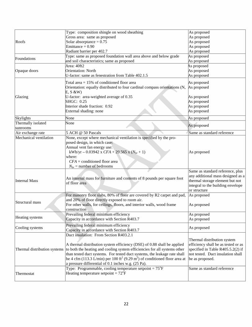
TABLE R405.5.2(1) SPECIFICATIONS FOR THE STANDARD REFERENCE AND PROPOSED DESIGNS
BUILDING COMPONENT STANDARD REFERENCE DESIGN PROPOSED DESIGN
Above-grade walls
Type: mass wall if proposed wall is mass; otherwise wood frame Gross area: same as proposed U-factor: from Table R402.1.4(2) Solar absorptance = 0.75 Emittance = 0.90
As proposed As proposed As proposed As proposed As proposed
Basement and crawl space walls
Type: same as proposed Gross area: same as proposed U-factor: from Table R402.1.4(2), with insulation layer on interior side of walls.
As proposed As proposed As proposed
Above-grade floors Type: wood frame Gross area: same as proposed U-factor: from Table R402.1.4(2)
As proposed As proposed As proposed
Ceilings Type: wood frame Gross area: same as proposed U-factor: from Table R402.1.4(2)
As proposed As proposed As proposed
22
Roofs
Type: composition shingle on wood sheathing Gross area: same as proposed Solar absorptance = 0.75 Emittance = 0.90 Radiant barrier per 402.7
As proposed As proposed As proposed As proposed As proposed
Foundations Type: same as proposed foundation wall area above and below grade and soil characteristics; same as proposed
As proposed As proposed
Opaque doors Area: 40ft2 Orientation: North U-factor: same as fenestration from Table 402.1.5
As proposed As proposed As proposed
Glazing
Total area = 15% of conditioned floor area Orientation: equally distributed to four cardinal compass orientations (N, E, S &W) U-factor: area-weighted average of 0.35 SHGC: 0.25 Interior shade fraction: 0.92 External shading: none
As proposed As proposed As proposed As proposed As proposed As proposed
Skylights None As proposed Thermally isolated sunrooms
None As proposed
Air exchange rate 5 ACH @ 50 Pascals Same as standard reference Mechanical ventilation None, except where mechanical ventilation is specified by the pro-
posed design, in which case: Annual vent fan energy use: kWh/yr – 0.03942 x CFA + 29.565 x (Nbr + 1) where: CFA = conditioned floor area Nbr = number of bedrooms
As proposed
Internal Mass An internal mass for furniture and contents of 8 pounds per square foot of floor area
Same as standard reference, plus any additional mass designed as a thermal storage element but not integral to the building envelope or structure
Structural mass
For masonry floor slabs, 80% of floor are covered by R2 carpet and pad, and 20% of floor directly exposed to room air. For other walls, for ceilings, floors, and interior walls, wood frame construction
As proposed As proposed
Heating systems Prevailing federal minimum efficiency Capacity in accordance with Section R403.7
As proposed As proposed
Cooling systems Prevailing federal minimum efficiency Capacity in accordance with Section R403.7 As proposed
Thermal distribution systems
Duct insulation: From Section R403.2.1 A thermal distribution system efficiency (DSE) of 0.88 shall be applied to both the heating and cooling system efficiencies for all systems other than tested duct systems. For tested duct systems, the leakage rate shall be 4 cfm (113.3 L/min) per 100 ft2 (9.29 m2) of conditioned floor area at a pressure differential of 0.1 inches w.g. (25 Pa).
Thermal distribution system efficiency shall be as tested or as specified in Table R405.5.2(2) if not tested. Duct insulation shall be as proposed.
Thermostat Type: Programmable, cooling temperature setpoint = 75oF Heating temperature setpoint = 72oF
Same as standard reference
23
R406.2 Mandatory requirements. Compliance with this section requires that the mandatory provisions identified in Sections R401, et sequiter, be met. The building thermal envelope shall be greater than or equal to levels of efficiency and Solar Heat Gain Coefficient in Table 402.1.1 and Table 402.1.3 of the 2009 Austin Energy Code.
R406.3 Energy Rating Index. The Energy Rating Index (ERI) shall be a numerical integer value that is based on a linear scale constructed such that the ERI reference design has an Index value of 100 and a residential building that uses o net purchased energy has an Index value of 0. Each integer value on the scale shall represent a 1-percent change in the total energy use of the rated design relative to the total energy use of the ERI reference design. The ERI shall consider all energy used in the residential building. Calculation of the ERI shall not include on-site power production.