HYDRAULIC ENGINEERING OPEN-CHANNEL FLOW 103 AN OVERVIEW OF GUNT EXPERIMENTAL FLUMES GUNT experimental flumes and their accessories open up a wide range of experiments and demonstrations on the topics of open-channel flow, running waters, hydraulic engineering and coastal protection. They form the expandable foundation for custom investigations and research work. Experimental flumes from GUNT have been successfully put to use around the world for many years. For each of the experimental flumes, there is a variety of models for discharge control, such as weirs, sills, stilling basins, as well as wave generators, beach elements and bridge piers. Technical solutions for sediment feed and removal are also available. In addition, we can also provide specially adapted instru- mentation such as water level gauges, pitotstatic tubes, tube manometers and velocity meters. GUNT provides three experimental flumes with different cross-sections, depending on the purpose of use and the local conditions: HM 160 (86 x 300 mm), HM 162 (309x450mm) and HM 161 (600x800mm). Two of the experimental flumes have different lengths of experimental section to choose from: HM 160 with 2,5m or 5m and HM 162 with experimental sections of 5m, 7,5m, 10m or 12,5m. As a result, the length of the experimental section can be adjusted to the individual requirements of the laboratory. HM 161 is the largest GUNT experimental flume and has an experimental section that is 16m long. The HM 160 flume is perfectly suited as an introduction to the topic of “Open-Channel Flow” and the demonstra- tion of many of the basic principles. The experimental flume even fits in lecture theatres, as it is relatively small and compact. HM 160 with an experimental section of 2,5m requires an area of approximately 6x4m, including sufficient space to observe the experiments. This allows the instructor to provide practical demonstrations of phenomena during lectures. The HM 162 experimental flume can be supplied in four different lengths. The “short” experimental flume, with an experimental section of 5 m, is particularly well suited for demonstrations and can easily be set up even in smaller laboratories. As the length of the experimental section increases – and the inlet and outlet conditions improve – the phenomena become closer to those observed in reality. For example, with an experimental section of 12,5 m we can clearly see to what extent a damming body affects the upstream flow. The largest GUNT experimental flume HM 161 – with a cross-section of 600 x 800 mm and a 16 m long experimen- tal section – offers a large number of possibilities for your own research projects. The phenomena to be observed move beyond mere demonstration and become closer to reality. The HM 161 flume provides an initial impression of the natural force of water. HM 160 (5m) HM 161 HM 161 HM 162 (12,5m) 300 HM 160 HM 162 HM 161 Tried and trusted products: ...from small to large ...for demonstration and research 2 gunt An almost identical experimental flume with the cross-section of 409 x 500 mm is also available with the device code HM 163.
Transcript
HYDRAULIC ENGINEERING OPEN-CHANNEL FLOW
103
AN OVERVIEW OF GUNT EXPERIMENTAL FLUMES
GUNT experimental flumes and their accessories open up a wide range of experiments and demonstrations on the topics of open-channel flow, running waters, hydraulic engineering and coastal protection. They form the expandable foundation for custom investigations and research work. Experimental flumes from GUNT have been successfully put to use around the world for many years.
For each of the experimental flumes, there is a variety of models for discharge control, such as weirs, sills, stilling basins, as well as wave generators, beach elements and bridge piers. Technical solutions for sediment feed and removal are also available.
In addition, we can also provide specially adapted instru-mentation such as water level gauges, pitotstatic tubes, tube manometers and velocity meters.
GUNT provides three experimental flumes with different cross-sections, depending on the purpose of use and the local conditions: HM 160 (86x300mm), HM 162 (309x450mm) and HM 161 (600x800mm). Two of the experimental flumes have different lengths of experimental section to choose from: HM 160 with 2,5m or 5m and HM 162 with experimental sections of 5m, 7,5m, 10m or 12,5m. As a result, the length of the experimental section can be adjusted to the individual requirements of the laboratory. HM 161 is the largest GUNT experimental flume and has an experimental section that is 16m long.
The HM 160 flume is perfectly suited as an introduction to the topic of “Open-Channel Flow” and the demonstra-tion of many of the basic principles. The experimental flume even fits in lecture theatres, as it is relatively small and compact. HM 160 with an experimental section of 2,5m requires an area of approximately 6x4m, including sufficient space to observe the experiments. This allows the instructor to provide practical demonstrations of phenomena during lectures.
The HM 162 experimental flume can be supplied in four different lengths. The “short” experimental flume, with an experimental section of 5m, is particularly well suited for demonstrations and can easily be set up even in smaller laboratories.
As the length of the experimental section increases – and the inlet and outlet conditions improve – the phenomena become closer to those observed in reality. For example, with an experimental section of 12,5m we can clearly see to what extent a damming body affects the upstream flow.
The largest GUNT experimental flume HM 161 – with a cross-section of 600x800mm and a 16m long experimen-tal section – offers a large number of possibilities for your own research projects. The phenomena to be observed move beyond mere demonstration and become closer to reality. The HM 161 flume provides an initial impression of the natural force of water.
HM 160 (5m)
HM 161
HM 161
HM 162 (12,5m)
300
HM 160
HM 162
HM 161Tried and trusted
products:
...from small to large
...for demonstration and research
2 gunt
An almost identical experimental
flume with the cross-section of
409 x 500 mm is also available with
the device code HM 163.
HYDRAULIC ENGINEERING OPEN-CHANNEL FLOW
TECHNICAL DETAILS FOR GUNT EXPERIMENTAL FLU MES – THE CLOSED WATER CIRCUIT
All experimental flumes can be operated independently of the laboratory water supply and have a closed water circuit with water tanks, pump and flow meter. To protect
against overfilling of the experimental section, level switches turn off the pump when the maximum level in the inlet or outlet element is exceeded.
All experimental flumes allow adjusting the volumetric flow. The pump is fitted with a control butterfly valve or a gate valve equipped that is operated either manually (HM 160, HM 162) or electrically (HM 161) until the desired
flow rate is achieved. The flow rate in HM 160 is measured by a rotameter, while HM 161 and HM 162 are both equipped with an electromagnetic flow meter.
In all experimental flumes, the inlet element is designed for optimum flow so that the flow is less turbulent as it enters the experimental section.
The water enters from below through a flow straightener. A damping plate calms the water further. The damping plate floats on the water and is mounted on a guide.
In the plan view we can see that the inlet element has a nozzle-like contour.
The outlet element of all experimental flumes contains a plate weir. A maximum of two elements can be removed from this weir, so that two damming heights are available to choose from. If both elements are removed, it corre-
sponds to free discharge without a weir. Moreover, the weir is mounted to rotate around a fixed point and can thus be lowered. As such, any desired top water level can be set (see illustrations).
METHODS FOR ADJUSTING THE VOLUMETRIC FLOW IN THE INLET TO THE EXPERIMENTAL SECTION
The centrifugal pump is separated from the experimental section in both experimental flumes HM 162 and HM 161 and is mounted on its own foundation. It is connected to the piping to the inlet element via a hose. This ensures that there is no transmission of vibrations between the experimental section and the pump. In the small experi-mental flume HM 160 the vibrations that occur are negligi-ble, so the pump is integrated in one of the experimental flume’s supports.
THE WATER CIRCUIT THE INLET ELEMENT
THE OUTLET ELEMENT
THE PUMP
1 water tank,2 outlet element,3 pump,4 experimental section,5 control butterfly valve,6 inlet element,F flow meter
Principle of the plate weir with two damming heights: both elements used, only lower element used, max. height of damming if upper element has
been removed, max. height of damming when 2 elements are used;
1 plate weir, 2 removable element
Plate weir with full damming height in different positions to adjust the top water level in the outlet of the experimental section.
Plate weir with medium damming height in different positions to adjust the top water level in the outlet of the experimental section.
1 damping plate, 2 flow straightener,3 guide
Plan view of the inlet element with streamlines
1 water tank,2 pump,3 hose,4 flow meter
Pump (HM 162) with shut-off valve in the intake side (left) and control butterfly valve with manual actuation in the delivery side for adjusting the flow rate (above the pump). The pump’s delivery line also contains the hose and the electromagnetic flow meter.
105
2 gunt
HYDRAULIC ENGINEERING OPEN-CHANNEL FLOW
107
TECHNICAL DETAILS FOR GUNT EXPERIMENTAL FLU MES – STRUCTURAL FEATURES
MATERIALS USED
RIGIDITY AGAINST DEFORMATION
INCLINATION ADJUSTMENT
In all experimental flumes, the bottom of the experimen-tal section is made of stainless steel. Tempered glass is used for the side walls of the experimental section. It is scratch resistant, does not age and does not deform. The water tank, inlet and outlet elements are made of
corrosion-resistant GRP (glass reinforced plastic) or steel. The piping is PVC. The models used in the experimen-tal flumes consist of aluminium, stainless steel, PVC or Plexiglas.
The experimental section of HM 162 is available in several lengths. The components used are essentially the same (modular design). In order to realise different lengths with the modular design, while maintaining inclination adjustment, the experimental flume is supported by an auxiliary carrier with two supports. In the version with long experimental section, the inevitable deformations are absorbed by the supports. The individual adjustability of the elements enables precise alignment of the experi-mental section.
The elements of the self-supporting experimental section in HM 161 are mounted on 4 supports, so that there is only ever a minimal deformation.
In HM 160 the stresses that occur in comparison to HM 162 are small, so that doubling the length of the exper-imental section does not pose a problem for the rigidity of the self-supporting experimental flume with two supports.
All experimental flumes can be inclined, which means that the slope is adjustable. The slope range is -1/200...1/40. The current slope can be read directly on a scale (HM 160, HM 162) or a digital display (HM 161).
Inclination adjustment in HM 160 is manual and electrical in HM 161.
In HM 162 the inclination can be adjusted either manually or electrically. With an experimental section above 7,5m we recommend electrical inclination adjustment.
The rigidity of the elements of the experimental section against water pressure is ensured by the welded frame. The frames support the glass side walls.
Electrical inclination adjustment in HM 161
Manual inclination adjustment in HM 162:left: scale, right: entire mechanism
Manual inclination adjustment in HM 160
Bottom element of an element of the HM 162 experimental section, reinforced with diagonal ribs to increase stiffness against bending and torsion.
For all experimental flumes we can state that, with careful design, the maximum deviation from the ideal geometric shape for flatness and torsion is 0,1%. In the illustrations the deformations are shown greatly enlarged, e.g. 0,1% of the length L. In the general tolerances for straight-
ness and flatness according to ISO 2768, this satisfies the tolerance classes medium to fine. In this case the maximum deviation refers to the length of the experimen-tal section.
Side view of the experimental section: ideal flume bottom, deformation of the bottom by bending
Plan view of the experimental section: ideal contour of the side walls, deformed side walls
HM 161
HM 162
HM 160
carrier (rigidity against bending), frame (rigidity against water pressure), fixed support, height-adjustable support (flume inclination adjustment), experimental section, inlet and outlet element
1 welded frame,2 bottom element of an element of the experi- mental section,3 diagonal rib,F water pressure force
HM 160 HM 162 HM 161
2 gunt
HYDRAULIC ENGINEERING OPEN-CHANNEL FLOW
109
GUNT EXPERIMENTAL FLUMES: INSTRUMENTATION
Instrument carriers for HM 162 and HM 161
The experimental flumes HM 161 and HM 162 extend above the side wall guide rails. An instrument carrier can be placed on the rails and moved. The different instru-ments are mounted on the instrument carrier, for example a level gauge or a pitotstatic tube. Using the carrier, the instruments can be moved to nearly every point of the flow. The carrier can be locked during the measurements with fixing devices. The position of the carrier along the experimental section is read on a scale (see photo). On the carrier itself is another scale, used to determine the position transverse to the direction of flow.
In the small experimental flume HM 160 no instrument carrier is necessary. The instruments are placed directly on the top of the experimental section and clamped in place.
Flow velocity GUNT offers two methods of measuring the flow rate in all experimental flumes: the traditional pitotstatic tube or a digital velocity meter. The pitotstatic tube HM 16x.50 measures the static pressure and the total pressure at any point of the flow. A digital pressure gauge displays the difference between the two pressures. The pressure difference corresponds to the dynamic pressure, from which the flow velocity can be calculated.
The core element of the velocity meter HM 16x.64 is an impeller that is rotated by the flow. The speed of the impeller is proportional to the flow velocity. The flow velocity is read directly from the digital display.
Discharge depth To measure the discharge depth, the level gauge HM 16x.52 or HM 16x.91 with digital display is used. The tip of the probe is moved to the surface of the water from above.
Pressure measurement All experimental flumes are equipped with pressure measuring points in the flume bottom. The pressure measuring points are evenly distributed over the length of the experimental section. To read these pressures, the pressure measuring points are connected to the optional manometer panel HM 16x.53 via hoses. This allows directly reading a profile of discharge depth over the entire length of the experimen-tal section on the manometer panel.
Measuring methods in your laboratory
Of course, you can also use your own laboratory measuring methods to determine the flow velocity, such as PIV (Particle Image Velocimetry) or LDA (Laser
Doppler Anemometry) and ultrasound to determine the discharge depth.
The elements of the experimental section in the experi-mental flume HM 160 contain 10 pressure measuring points over a length of 2,5m. The manometer panel HM 160.53 contains 10 tubes.
In the experimental flume HM 161, forty-eight pressure measuring points are evenly distributed over the experi-mental section with 16 m length. The manometer panel HM 161.53 contains 20 tubes.
A broad-crested weir (HM 162.31) and a sluice gate (HM 162.29) have been inserted in the 5m long experi-mental section of HM 162. The elements of the experimen-tal section of HM 162 each contain 10 pressure measuring points, which are uniformly distributed over the length of the 2,5m element. The pressure at these measuring points is called the pressure head and corresponds to the discharge depth. The pressure heads are displayed on the manometer panel HM 162.53. When the experimental
section is inclined, i.e. open-channel flow with a slope, it is more accurate to measure the discharge depth via the pressure head than via a level gauge.
The manometer panel HM 162.53 contains 10 tubes Depending on the length of the experimental section, we can either represent selected points on a panel or use multiple panels to show all pressures.
Example of a pressure measurement along the experimental section
Instrument carrier with level gauge
Pitotstatic tube HM 162.50 with instrument carrier
Level gauge HM 162.52 with instrument carrier
Tube manometers HM 162.53
Scale along the experimental section
Velocity meter HM 16x.64
HM 162 with sluice gate 1, broad-crested weir 2 and manometer panel 3. The manometer panels are enlarged so they can be clearly seen.
InInInInststststrururur mememeentntn ccccaararara rrrlell vevvevevelll l l gagagagag ugugugugugeeeee
sesesesectctctctcc ioioioionnn
Setup of the instrument carrier
2 gunt
HYDRAULIC ENGINEERING OPEN-CHANNEL FLOW
111
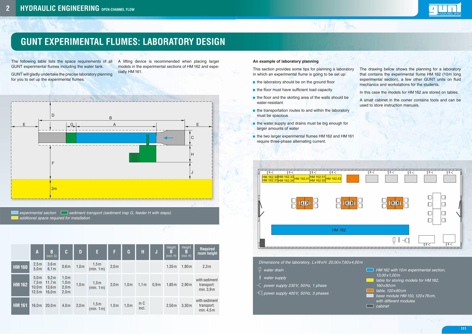
GUNT EXPERIMENTAL FLUMES: LABORATORY DESIGN
The following table lists the space requirements of all GUNT experimental flumes including the water tank.
GUNT will gladly undertake the precise laboratory planning for you to set up the experimental flumes.
A lifting device is recommended when placing larger models in the experimental sections of HM 162 and espe-cially HM 161.
An example of laboratory planning
This section provides some tips for planning a laboratory in which an experimental flume is going to be set up:
the laboratory should be on the ground floor
the floor must have sufficient load capacity
the floor and the skirting area of the walls should be water-resistant
the transportation routes to and within the laboratory must be spacious
the water supply and drains must be big enough for larger amounts of water
the two larger experimental flumes HM 162 and HM 161 require three-phase alternating current.
The drawing below shows the planning for a laboratory that contains the experimental flume HM 162 (10m long experimental section), a few other GUNT units on fluid mechanics and workstations for the students.
In this case the models for HM 162 are stored on tables.
A small cabinet in the corner contains tools and can be used to store instruction manuals.
experimental section sediment transport (sediment trap G, feeder H with steps) additional space required for installation
water drain
water supply
power supply 230V, 50Hz, 1 phase
power supply 400V, 50Hz, 3 phases
HM 162 with 10m experimental section, 13,00 x1,00m
table for storing models for HM 162, 160x80cm
table, 120x80cm base module HM 150, 120x76cm,
with different modules cabinet
HM 160
HM 162
HM 161
A B (excl. G)
C D F G H JHeight
B(excl. H)
E
1,5m (min. 1m)
1,5m (min. 1m)
1,5m (min. 1m)
1,0m
1,0m
2,0m
2,0m
2,0m
1,0m
1,0m
1,0m
1,1m
in C incl.
0,9m
1,35m
1,85m
2,50m
1,80m
2,90m
3,30m
2,3m
with sediment transport: min. 3,9m
with sediment transport: min. 4,5m
0,6m
1,0m1,0m2,0m2,0m
4,0m
3,6m6,1m
9,2m11,7m13,6m16,0m
20,0m
2,5m5,0m
5,0m7,5m
10,0m12,5m
16,0m
Required room height
Height B
(incl. H)
Dimensions of the laboratory, LxWxH: 20,00x7,60x4,00m
2 gunt
101101
HYDRAULIC ENGINEERING OPEN-CHANNEL FLOW
Control structures
Changes in cross-section (losses, fl ow formulae)
Discharge measurement
Other experiments: including waves, sediment transport
The appropriate instrumentation for measuring the discharge depth and the fl ow velocity is also available as additional accessories.
HM 162 with an experimental section of 7,5m
HM 162.29 Sluice Gate HM 162.40 Radial Gate
HM 162.31 Broad-Crested Weir HM 162.33 Crump Weir
HM 162.36 Siphon Weir HM 162.32 Ogee-Crested Weir with 2 Weir Outlets HM 162.35 Elements for Energy Dissipation
HM 162.34 Ogee-Crested Weir with Pressure Measurement
HM 162.77 Flume Bottom with Pebble StonesHM 162.45 Culvert
HM 162.46 Set of PiersHM 162.44 Sill
HM 162.30 Set of Plate Weirs
HM 162.51 Venturi Flume
HM 162.80 Set of Beaches
HM 162.55 Parshall Flume
HM 162.63 Trapezoidal Flume
OPEN-CHANNEL FLOW IN THE LAB
A wide range of typical models allows the user to design a broad and individual programme of experiments with GUNT experimental flumes. The programme of experiments shown in this catalogue for HM 162 applies, in principle, for all GUNT experimental flumes.
The models of the other GUNT experimental flumes are similar.