7 Flumes A critical depth-flume is essentially a geometrically specified constriction built in an open channel where sufficient fall is available for critical flow to occur in the throat of the flume. Flumes are ‘in-line’ structures, i.e. their centre line coincides with the centre line of the undivided channel in which the flow is to be measured. The flume cannot be used in structures like turnouts, controls and other regulating devices. In this chapter the following types of critical-depth flumes will be described: Long- throated flumes (7. I), Throatless flumes with rounded transition (7.2), Throatless flumes with broken plane transition (7.3), Parshall flumes (7.4), H-flumes (7.5). The name ‘Venturi flume’ is not used in this chapter, since this term is reserved for flumes in which flow in the constriction is sub-critical. The discharge through such a constric- tion can be calculated by use of the equations presented in Section 1.7. 7.1 Long-throated flumes 7.1.1 Description Classified under the term ‘long-throated flumes’ are those structures which have a throat section in which the streamlines run parallel to each other at least over a short distance. Because of this, hydrostatic pressure distribution can be assumed at the con- trol section. This assumption allowed the various head-discharge equations to be de- rived, but the reader should note that discharge coefficients are also presented for high H,/L ratios when the streamlines at the control are curved. The flume comprises a throat of which the bottom (invert) is truly horizontal in the direction of flow. The crest level of the throat should not be lower than the dead water level in the channel, i.e. the water level downstream at zero flow. The throat section is prismatic but the shape of the flume cross-section is rather arbitrary, pro- vided that no horizontal planes, or planes that are nearly so, occur in the throat above crest (invert) level, since this will cause a discontinuity in the head-discharge relation- ship. Treated in this section will be the most common flumes, i.e. those with a rectangu- lar, V-shaped, trapezoïdal, truncated V, parabolic, or circular throat cross-section. For other shapes see Bos (1985). The entrance transition should be of sufficient length, so that no flow separation can occur either at the bottom or at the sides of the transition. The transition can be formed of elliptical, cylindrical, or plane surfaces. For easy construction, a transi- tion formed of either cylindrical or plane surfaces, or a combination of both, is recom- mended. If cylindrical surfaces are used, their axes should be parallel to the planes of the throat and should lie in the cross-section through the entrance of the throat. Their radii should preferably be about 2 Hlmax. With a plane surfaced transition, the convergence of side walls and bottom should be about 1.3. According to Wells & Gotaas (1956) and Bos & Reinink (1 98 l), minor changes in the slope of the entrance transition will have no effect upon the accuracy of the flume. It is suggested that, where the flume has a bottom contraction or hump, the transitions for the crest and for the sides should be of equal lengths, i.e. the bottom and side contraction should begin at the same point at the approach channel bottom as shown in Figure 7. I. 209
Transcript
7 Flumes
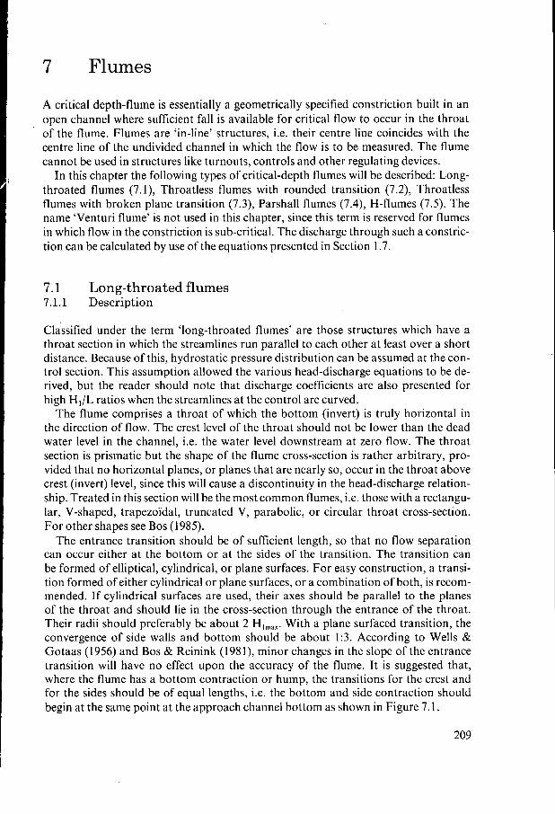
A critical depth-flume is essentially a geometrically specified constriction built in an open channel where sufficient fall is available for critical flow to occur in the throat of the flume. Flumes are ‘in-line’ structures, i.e. their centre line coincides with the centre line of the undivided channel in which the flow is to be measured. The flume cannot be used in structures like turnouts, controls and other regulating devices.
In this chapter the following types of critical-depth flumes will be described: Long- throated flumes (7. I), Throatless flumes with rounded transition (7.2), Throatless flumes with broken plane transition (7.3), Parshall flumes (7.4), H-flumes (7.5). The name ‘Venturi flume’ is not used in this chapter, since this term is reserved for flumes in which flow in the constriction is sub-critical. The discharge through such a constric- tion can be calculated by use of the equations presented in Section 1.7.
7.1 Long-throated flumes 7.1.1 Description
Classified under the term ‘long-throated flumes’ are those structures which have a throat section in which the streamlines run parallel to each other at least over a short distance. Because of this, hydrostatic pressure distribution can be assumed at the con- trol section. This assumption allowed the various head-discharge equations to be de- rived, but the reader should note that discharge coefficients are also presented for high H,/L ratios when the streamlines at the control are curved.
The flume comprises a throat of which the bottom (invert) is truly horizontal in the direction of flow. The crest level of the throat should not be lower than the dead water level in the channel, i.e. the water level downstream at zero flow. The throat section is prismatic but the shape of the flume cross-section is rather arbitrary, pro- vided that no horizontal planes, or planes that are nearly so, occur in the throat above crest (invert) level, since this will cause a discontinuity in the head-discharge relation- ship. Treated in this section will be the most common flumes, i.e. those with a rectangu- lar, V-shaped, trapezoïdal, truncated V, parabolic, or circular throat cross-section. For other shapes see Bos (1985).
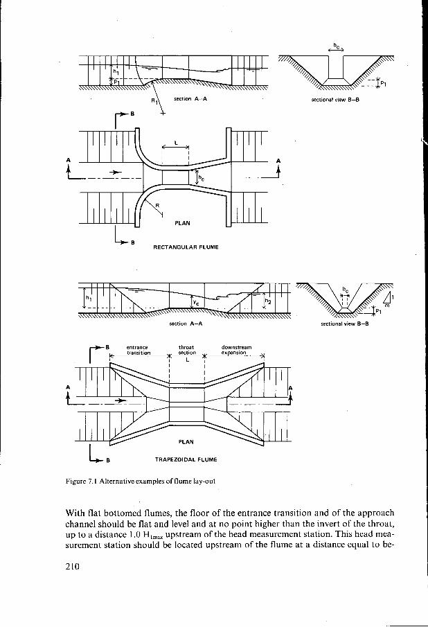
The entrance transition should be of sufficient length, so that no flow separation can occur either at the bottom or at the sides of the transition. The transition can be formed of elliptical, cylindrical, or plane surfaces. For easy construction, a transi- tion formed of either cylindrical or plane surfaces, or a combination of both, is recom- mended. If cylindrical surfaces are used, their axes should be parallel to the planes of the throat and should lie in the cross-section through the entrance of the throat. Their radii should preferably be about 2 Hlmax. With a plane surfaced transition, the convergence of side walls and bottom should be about 1.3. According to Wells & Gotaas (1 956) and Bos & Reinink ( 1 98 l), minor changes in the slope of the entrance transition will have no effect upon the accuracy of the flume. It is suggested that, where the flume has a bottom contraction or hump, the transitions for the crest and for the sides should be of equal lengths, i.e. the bottom and side contraction should begin at the same point at the approach channel bottom as shown in Figure 7. I .
209
"1 section A-A
r B
sectional view B-B
RECTANGULAR FLUME
section A-A sectional view B-B
throat downsTream section expansion
m
L B TRAPEZOIDAL FLUME
Figure 7. I Alternative examples of flume lay-out
With flat bottomed flumes, the floor of the entrance transition and of the approach channel should be flat and level and at no point higher than the invert of the throat, up to a distance 1 .O Hlmax upstream of the head measurement station. This head mea- surement station should be located upstream of the flume at a distance equal to be-
210
HEAD-DISCHARGE EQ. TO BE USED
HOW TO FIND THEY,-VALUE
1 /2 Q = CdCV 3 (3 g) b,h:/z
I f H1 < 0.70 d,
Q = CddFfi [f(S)]
use table 7.2 to find f(Bl
I f H1 b 0.70 d, Q = C c 2 ( 2 g ) 1/2 dc(h~-0.1073d,) 3/2
d v 3 3
Use Table 3.1
Use Table 7.2
Use Table 7.2
y, = $ Hl + 0.0358dC
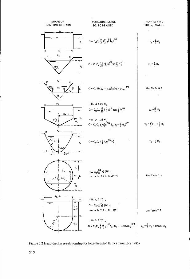
Figure 7.2 Head-discharge relationship for long-throated flumes (from Bos 1985)
212
Cd value 1.16 I
21 3
Table 7.1 Values of the ratio yc/HI as a function of zc and Hl/bc for trapezoïdal control sections ~
Side slopes of channel, ratio of horizontal to vertical (zc: I )
The modular limit of flumes greatly depends on the shape of the downstream expan- sion. The relation between the modular limit and the angle of expansion, can be ob- tained from Section l . 15. Practice varies between very gentle and costly expansions of about 1-to-15, to ensure a high modular limit, and short expansions of 1-to-6. It is recommended that the divergences of each plane surface be not more abrupt than I-to-6. If in some circumstances it is desirable to construct a short downstream expan- sion, it is better to truncate the transition rather than to enlarge the angle of divergence (see also Figure 1.35). At one extreme if no velocity head needs to be recovered, the downstream transition can be fully truncated. It will be clear from Section 1.15 that no expanding section will be needed if the tailwater level is always less than yc above the invert of the flume throat.
At the other extreme, when almost all velocity head needs to be recovered, a transi- tion with a gradual expansion of sides and bed is required. The modular limit of long- throated flumes with various control cross sections and downstream expansions can be estimated with the aid of Section 1.15.
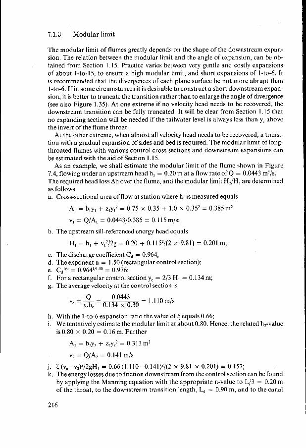
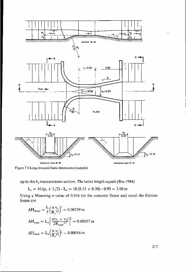
As an example, we shall estimate the modular limit of the flume shown in Figure 7.4, flowing under an upstream head h, = 0.20 m at a flow rate of Q = 0.0443 m3/s. The required head loss Ah over the flume, and the modular limit H,/H, are determined as follows a. Cross-sectional area of flow at station where h, is measured equals
A, = b,y, + z,y,, = 0.75 x 0.35 + 1.0 x 0.35, = 0.385m2
v, = Q/A, = 0.0443/0.385 = O. 11 5 m/s;
b. The upstream sill-referenced energy head equals
H, = h, + vI2/2g = 0.20 + 0.1 15,/(2 x 9.81) = 0.201 m;
c. The discharge coefficient C d = 0.964; d. The exponent u = 1.50 (rectangular control section);
f. For a rectangular control section yc = 2/3 Hl = O. 134 m; g. The average velocity at the control section is
e. cd”” = 0.964”’ = 0.976;
= 1.110m/s Q 0.0443 v =-= ycb, 0.134 x 0.30
h. With the 1-to-6 expansion ratio the value of 6 equals 0.66; i. We tentatively estimate the modular limit at about 0.80. Hence, the related h,-value
is 0.80 x 0.20 = 0.16 m. Further
A, = b2y2 + z,y,2 = 0.3 13 m2
v2 = Q/A, = 0.141 m/s
j. ~ ( ~ , - v , ) ~ / 2 g H , = 0.66(l.110-0.141)2/(2 x 9.81 x 0.201) = 0.157; k. The energy losses due to friction downstream from the control section can be found
by applying the Manning equation with the appropriate n-value to L/3 = 0.20 m of the throat, to the downstream transition length, Ld = 0.90 m, and to the canal
up to the h, measurement section. The latter length equals (Bos 1984)
Le = I O (p l + L/2) - L, = 10 (O. 15 + 0.30) - 0.90 = 3.60 m
Using a Manning n-value of 0.016 for the concrete flume and canal the friction losses are
L nv, AHthroa, = 3(F) = 0.00239 m
AH,,,,, = Ld p,,r+;?r = 0.00057 m
AHcana, = = 0.00016m
217
Hence AH, N 0.003 m. It should be noted that for low h,-values and relatively long transitions, the value of AH, becomes significantly more important. The value of AH, is relatively insensitive for minor changes of the tailwater depth y,. Hence, for a subsequent pass through this step in the procedure the same AH,-value may be used;
I. Calculate AHdH, = 0.003/0.201 = 0.01 5; m. The downstream sill-referenced energy head at the tailwater depth used at Step
i equals
H, = h, + v,2/2g = 0.16 + 0.14,/(2 x 9.81) = 0.161 m
n. The ratio H,/H, equals then 0.801; o. Substitution of the values of steps e, j, I, and n into Equation 1.125 gives at modular
limit H,/H,
0.801 = 0.976-0.015-0.157 = 0.804
which is almost true. Hence, h , - h, = 0.04 m for this flume if h, = 0.20 m. Once some experience has been acquired a close match of Equation 1.125 can be ob- tained in two to three iterations. Since the modular limit varies with the upstream head, it is advisable to estimate the modular limit at both minimum and maximum anticipated flow rates and to check if sufficient head loss is available. The computer program FLUME (Clemmens et al. 1987) calculates the modular limit and head loss requirement for broad-crested weirs and long-throated flumes.
7.1.4 Limits of application
The limits of application of a long-throated flume for reasonably accurate flow measurements are: a. The practical lower limit of h, is related to the magnitude of the influence of fluid
properties, boundary roughness, and the accuracy with which h, can be determined. The recommended lower limit is 0.07 L;
b. To prevent water surface instability in the approach channel the Froude number Fr = vI/(gAI/Bl)'/2 should not exceed 0.5;
c. The upper limitation on the ratio H,/L arises from the necessity to prevent stream- line curvature in the flume throat. Values of the ratio H, /L should be less than 1 .o;
d. The width B, of the water surface in the throat at maximum stage should not be less than L/5;
e. The width at the water surface in a triangular throat at minimum stage should not be less than 0.20 m.
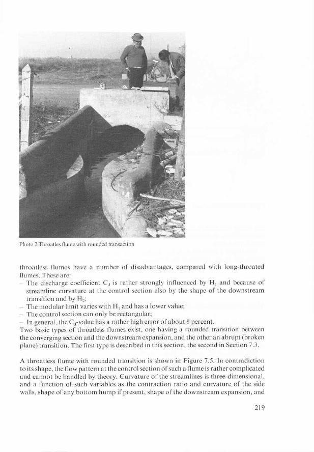
7.2 Throatless flumes with rounded transition 7.2.1 Description
Throatless flumes may be regarded as shorter, and thus cheaper, variants of the long- throated flumes described in Section 7.1. Although their construction costs are lower,
218
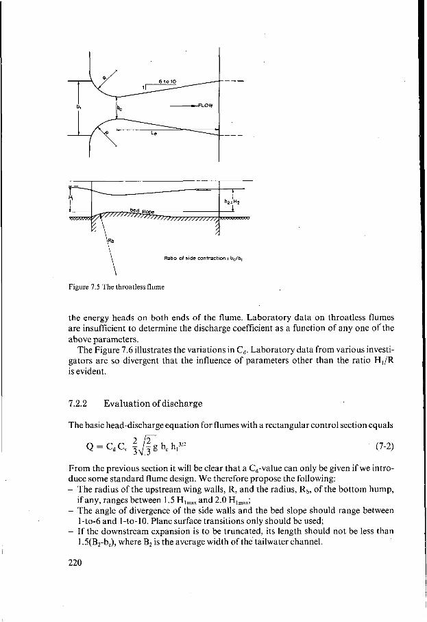
Ratio of side contraction: b,/b, \ Figure 7.5 The throatless flume
the energy heads on both ends of the flume. Laboratory data on throatless flumes are insufficient to determine the discharge coefficient as a function of any one of’the above parameters.
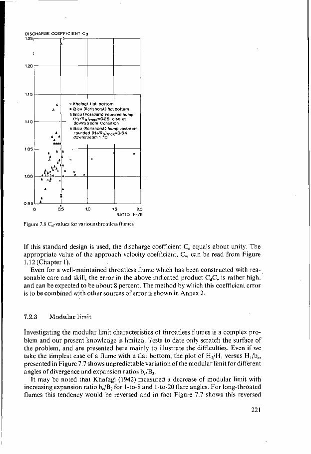
The Figure 7.6 illustrates the variations in Cd. Laboratory data from various investi- gators are so divergent that the influence of parameters other than the ratio H,/R is evident.
7.2.2 Evaluation of discharge
The basic head-discharge equation for flumes with a rectangular control section equals
(7-2) 2 2 Q = CdCV 3&g b, h,3/2
From the previous section it will be clear that a Cd-value can only be given if we intro- duce some standard flume design. We therefore propose the following: - The radius of the upstream wing walls, R, and the radius, Rb, of the bottom hump,
- The angle of divergence of the side walls and the bed slope should range between
- If the downstream expansion is to be truncated, its length should not be less than
if any, ranges between 1.5 Hlmax and 2.0 Hlmax;
1-to-6 and I-to-10. Plane surface transitions only should be used;
1 .5(B2-b,), where B, is the average width of the tailwater channel.
220
DISCHARGE COEFFICIENT Cd I
A 1 I A Blau (Karlshorst) f lat bottem 0 Khafagi flat bottom
A Wou (Potsdam) rounded hump ( H ~ / R b ) ~ ~ ~ = 0 . 2 5 also at downstream transitlon
rounded (H1/Rb)max=+0.64 downstream 1 :10
A Blou (Karlshorst) hump upstream
I I
O 0 5 1 .o 1.5 2.0 RATIO H1/R
Figure 7.6 Cd-values for various throatless flumes
If this standard design is used, the discharge coefficient Cd equals about unity. The appropriate value of the approach velocity coefficient, C,, can be read from Figure 1.12 (Chapter 1).
Even for a well-maintained throatless flume which has been constructed with rea- sonable care and skill, the error in the above indicated product cdc, is rather high, and can be expected to be about 8 percent. The method by which this coefficient error is to be combined with other sources of error is shown in Annex 2.
7.2.3 Modular limit
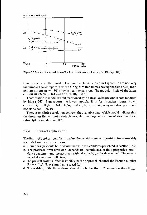
Investigating the modular limit characteristics of throatless flumes is a complex pro- blem and our present knowledge is limited. Tests to date only scratch the surface of the problem, and are presented here mainly to illustrate the difficulties. Even if we take the simplest case of a flume with a flat bottom, the plot of H2/H, versus H,/b,, presented in Figure 7.7 shows unpredictable variation of the modular limit for different angles of divergence and expansion ratios b,/B2.
I t may be noted that Khafagi (1942) measured a decrease of modular limit with increasing expansion ratio b,/B, for 1-to-8 and 1-to-20 flare angles. For long-throated flumes this tendency would be reversed and in fact Figure 7.7 shows this reversed
trend for a 1-to-6 flare angle. The modular limits shown in Figure 7.7 are not very favourable if we compare them with long-throated flumes having the same b,/B, ratio and an abrupt (a = 180’) downstream expansion. The modular limit of the latter equal 0.70 if bc/B2 .= 0.4 and 0.75 if b,/B, = 0.5.
The variation in modular limit mentioned by Khafagi is also present in data reported by Blau (1960). Blau reports the lowest modular limit for throatless flumes, which equals 0.5; for Hl/bc = 0.41, AJA, = 0.21, bJB, = 0.49, wingwall divergence and bed slope both I -to- 1 O.
There seems little correlation between the available data, which would indicate that the throatless flume is not a suitable modular discharge measurement structure if the ratio H,/H, exceeds about 0.5.
7.2.4 Limits of application
The limits of application of a throatless flume with rounded transition for reasonably accurate flow measurements are: a. Flume design should be in accordance with the standards presented in Section 7.2.2; b. The practical lower limit of h, depends on the influence of fluid properties, boun-
dary roughness, and the accuracy with which is h, can be determined. The recom- mended lower limit is 0.06 m;
c. To prevent water surface instability in the approach channel the Froude number Fr = v,/(gA,/B,)”~ should not exceed 0.5;
d. The width b, of the flume throat should not be less than 0.20 m nor less than HI,,,.
222
7.3 7.3.1 Description
Throatless flumes with broken plane transition
The geometry of the throatless flume with broken plane transition was first developed in irrigation practice in the Punjab and as such is described by Harvey (1912). Later, Blau (1960) reports on two geometries of this flume type. Both sources relate discharge and modular limit to heads upstream and downstream of the flume, h, and h, respecti- vely. Available data are not sufficient to warrant inclusion in this manual.
Since 1967 Skogerboe et al. have published a number of papers on the same flume, referring to it as the ‘cutthroat flume’. In the cutthroat flume, however, the flume discharge and modular limit are related to the piezometric heads at two points, in the converging section (ha) and in the downstream expansion (hb) as with the Parshall flume. Cutthroat flumes have been tested with a flat bottom only. A dimension sketch of this structure is shown in Figure 7.8.
Because of gaps in the research performed on cutthroat flumes, reliable head- discharge data are only available for one of the tested geometries (b, = 0.305 m, overall length is 2.743 m). Because of the non-availability of discharge data as a function of hl and h, (or Hl and H,) the required loss of head over the flume to maintain modu- larity is difficult to determine.
In the original cutthroat flume design, various discharge capacities were obtained by simply changing the throat width b,. Flumes with a throat width of I , 2, 3,4, 5, and 6 feet (1 ft = 0.3048 m) were tested for heads ha ranging from 0.06 to 0.76 m. All flumes were placed in a rectangular channel 2.44 m wide. The upstream wingwall had an abrupt transition to this channel as shown in Figure 7.8.
Obviously, the flow pattern at the upstream piezometer tap is influenced by the ratio b,/B,. Eggleston (1967) reports on this influence for a 0.3048 m wide flume. A variation of discharge at constant ha up to 2 percent was found. We expect, however, that this variation will increase with increasing width b, and upstream head. Owing to the changing entrance conditions it even is possible that the piezometer tap for
2.743
Figure 7.8 Cutthroat flume dimensions (after Skogerboe et al. 1967)