IRRIGATION AND DRAINAGE Irrig. and Drain. 54: 231-247 (2005) Putdished online in Wiley Interscience (www.interscience.wi1ey.corn). DOI: 10.1002/ird.160 SIMPLIFIED DESIGN OF FLUMES AND WEIRS+ I i TONY L. WAHL'*, ALBERT J CLEMMENS'; JOHN A. REPLOGLE? AND MARINUS G!, BOS' I US Dept. of the Interior; Bttreau of Reclamation, Water Resources Research Laboratory, D-8560, PO Box 25007, Denv r; CO 80225 US Water Conservation Lnborutory (USWCL),Agricultural Research Service, USDA USWCL, Agricultural Research Service, USDA ~nternntional Institute for Land Reclamation and Improvement (Alterra-ILRI), The Netherlands I ABSTRACT Long-throated flumes and broad-crested weirs have become accepted standards for open-channel fl w measure- ment during the past two decades. These structures offer the accuracy and reliability of critica -depth flow measurement, theoretically based calibrations, the lowest head loss requirement of any critical flow device, and extraordinary design and construction flexibility. Computer software developed in recent years has str amlined the I design and calibration process. The software, WinFlume, has been described in several papers and recent text. Although VIinFlume is vcry easj: to use, there is still a need for simplified design and calibration tools f r situations 4 where use of the computer model is not possible or desirable. This paper combines several previoys efforts to provide such tools in both metric and English units for the most typical measurement applications en ountered in irrigation and drainage: systems. Pre-computed designs for trapezoidal broad-crested weirs, long-thr ated flumes with rectangular control sections, broad-crested weirs in circular pipes, V-shaped long-throated umes, and portable RBC flumes are presented in easy-to-use tables that provide head and discharge ranges, onstruction dimensions, head loss requirements, and flume rating equation parameters. The use of the tables is d 1 monstrated with examples, and construction methods are illustrated. Copyright 0 2005 John Wiley & Sons, Lt . d KEY WORDS: HOW measurement; flumes; weirs I Au cours des vingt dernikres annCes, des canaux jaugeurs B col allongC et des dCversoirs B cr&tedpaisse sont devenus les normes acc:eptCes pour les mesures de dCbit B surface libre. Ces structures posskdent l'exa titude et la fiabilitk des mesures das debits de profondeur critique, des Ctalonnages thCoriques, la caractQistique de perte de charge la plus basse de n'importe quel dispositif d'Ccoulement critique et une extraordinaire s uplesse de conception et de fabrication. Un logiciel dCvelopp6 ces dernikres annCes a simplifiC les modalites de c nception et d'etalonnage. Le logiciel, WinFlume, a CtC dtcrit dans plusieurs articles et dans un l.exte rCcen 1 . Bien que WinFlume soit d'un err~ploi trks facile, on a toujours besoin de conception et d'outils d7Ctalonnage si les cas oh la modtlisation par ordinateur n'est pas possible ou pas souhaitable. Cet article associe effectuCs auparavant pour fournir de tels outils utilisant des unitts mesures les plus courailts rencontrCs dans les systkmes de pour des dkversoirs h trapCzo'idaux B cr&te Cpaisse, des canaux jaugeurs B col rectangulaires, des dCversoirs B crste Cpaisse dans des tuyaux circulaires, des des canaux jaugeurs po.rtables RBC sont prCsentCs dans des tableaux faciles *Correspondence to: Tony 1 , . Wahl, U.S. Dept. of the Interior, Bureau of Reclamation, Water Resources Research Labor tory, D-8560, PO Box 25007, Denver, CO ,30225-0007.E-mail: [email protected]+La conception sirnplifitie det; canaux jaugeurs et des d6versoirs. I Copyright 0 2005 John Wiley & Sons, Ltd. Received 30 A gust 2004 Revised 13 Dec ! mber 2004 Accepted 19 ~ecdmber 2004
Transcript
IRRIGATION AND DRAINAGE
Irrig. and Drain. 54: 231-247 (2005)
Putdished online in Wiley Interscience (www.interscience.wi1ey.corn). DOI: 10.1002/ird.160
SIMPLIFIED DESIGN OF FLUMES AND WEIRS+
I i TONY L. WAHL'*, ALBERT J CLEMMENS'; JOHN A. REPLOGLE? AND MARINUS G!, BOS'
I US Dept. of the Interior; Bttreau of Reclamation, Water Resources Research Laboratory, D-8560, PO Box 25007, Denv r; CO 80225 US Water Conservation Lnborutory (USWCL), Agricultural Research Service, USDA
USWCL, Agricultural Research Service, USDA ~nternntional Institute for Land Reclamation and Improvement (Alterra-ILRI), The Netherlands
I
ABSTRACT
Long-throated flumes and broad-crested weirs have become accepted standards for open-channel fl w measure- ment during the past two decades. These structures offer the accuracy and reliability of critica -depth flow measurement, theoretically based calibrations, the lowest head loss requirement of any critical flow device, and extraordinary design and construction flexibility. Computer software developed in recent years has str amlined the I design and calibration process. The software, WinFlume, has been described in several papers and recent text. Although VIinFlume is vcry easj: to use, there is still a need for simplified design and calibration tools f r situations 4 where use of the computer model is not possible or desirable. This paper combines several previoys efforts to provide such tools in both metric and English units for the most typical measurement applications en ountered in irrigation and drainage: systems. Pre-computed designs for trapezoidal broad-crested weirs, long-thr ated flumes with rectangular control sections, broad-crested weirs in circular pipes, V-shaped long-throated umes, and portable RBC flumes are presented in easy-to-use tables that provide head and discharge ranges, onstruction dimensions, head loss requirements, and flume rating equation parameters. The use of the tables is d 1 monstrated with examples, and construction methods are illustrated. Copyright 0 2005 John Wiley & Sons, Lt . d KEY WORDS: HOW measurement; flumes; weirs I
Au cours des vingt dernikres annCes, des canaux jaugeurs B col allongC et des dCversoirs B cr&te dpaisse sont devenus les normes acc:eptCes pour les mesures de dCbit B surface libre. Ces structures posskdent l'exa titude et la fiabilitk des mesures das debits de profondeur critique, des Ctalonnages thCoriques, la caractQistique de perte de charge la plus basse de n'importe quel dispositif d'Ccoulement critique et une extraordinaire s uplesse de conception et de fabrication. Un logiciel dCvelopp6 ces dernikres annCes a simplifiC les modalites de c nception et d'etalonnage. Le logiciel, WinFlume, a CtC dtcrit dans plusieurs articles et dans un l.exte rCcen 1 . Bien que WinFlume soit d'un err~ploi trks facile, on a toujours besoin de conception et d'outils d7Ctalonnage si les cas oh la modtlisation par ordinateur n'est pas possible ou pas souhaitable. Cet article associe effectuCs auparavant pour fournir de tels outils utilisant des unitts mesures les plus courailts rencontrCs dans les systkmes de pour des dkversoirs h trapCzo'idaux B cr&te Cpaisse, des canaux jaugeurs B col rectangulaires, des dCversoirs B crste Cpaisse dans des tuyaux circulaires, des des canaux jaugeurs po.rtables RBC sont prCsentCs dans des tableaux faciles
*Correspondence to: Tony 1,. Wahl, U.S. Dept. of the Interior, Bureau of Reclamation, Water Resources Research Labor tory, D-8560, PO Box 25007, Denver, CO ,30225-0007. E-mail: [email protected] +La conception sirnplifitie det; canaux jaugeurs et des d6versoirs. I Copyright 0 2005 John Wiley & Sons, Ltd.
Received 30 A gust 2004 Revised 13 Dec ! mber 2004
Accepted 19 ~ e c d m b e r 2004
Copyright notice
This article was prepared by a Bureau of Reclamation employee acting within the scope of their official duties. Copyright protection under U.S. copyright law is not available for such works. Although the private publication in which the article appears is itself copyrighted, this does not affect works of the U.S. Government, which can be freely reproduced by the public.
232 T. L. WAHL ETAL. 1
charge et de dCbit, les dimensions de la construction, les caractkristiques de perte de charge et les parambtr 1'Cquation de notation du canal jaugeur. L'utilisation des tableaux est dCmontrte i l'aide d'exemples mCthodes de fabrication sont illustsCes. Copyright 0 2005 John Wiley & Sons, Ltd.
MOTS CLBS: mesure du d6bit; canaux jaugeurs; diversoirs
INTRODUCTION
The terins "long-throated flume" and "broad-crested weir" encompass a large family of structures measure discharge in open chmnels. Other names comn~only used to weir, and Replogle flume or ,weir. These structures all have raised sill and/or narrowed throat section within which critical-depth flow is produced. In addition, the sill or throat in the direction of flow is sufficient that the streamlines passing through the essentially parallel to one another. This characteristic allows established be used to determine the calibration relationship between the
were described by Clemmens
in the approach channel upstream from the sill or throat (Clemmens et al., 2001). Although the the straightforward, the required calculations are iterative and tedious, and thus a number of computer program been developed in recent year:; to assist in the design and calibration of these devices. The latest of these co programs is WinFlume (Wahl et al., 2000). The program operates on Microsoft Windows-based computer available free of charge to the public from a website maintained by the Bureau of Reclamation. Earlier p
An important component of transition. Older broad-crested still allowed some flow separati influenced the flow at the crit through laboratory or field testi was realized that a suitably gradual transition would simplify the flow condition at the critical section.
Long-throated flumes (this above) have the lowest head lo jn existing canal systems. Rati program for any combination of prismatic approach channels and control sections, as long as constructed so that it is level structures using as-built dimfnsions exactly to specification (assuming th debris easily and can be desig than other critical-flow devices. All of these advantages have led long-throated flumes to become choice for many open-channel flow measurement applications.
Flume design and selection ~ ~ Design is a two-step process. First, the control section shape is selected and its elevation set to allow the
range of flows to be measured iiccurately without incurring excess submergence of the control section or undue increase in water levels upstream from the site. Once the control section is selected, the approach channel, converging transition, throat, and optional diverging transition are determined.
When WinFlume is used to design a flume, six design criteria are evaluated:
The upstream head at maximum discharge must be sufficient to prevent submergence of the The upstream head at minimum discharge must be sufficient to prevent submergence of the
Copyright 0 2005 John Wiley & Sons, Ltd.
SIMPLIFIED DESIGN OF FLUMES AND WEIRS 1 233
The upstream flow depth at maximum discharge should not encroach upon the required free oard in the upstream channel The Froude number in the approach channel should be less than 0.5 to ensure a stable water s rface in the approach channel
must meet the designer's objective at maximum discharge
." The combined flow measurement uncertainty considering both rating table and head
The combined flow measurement uncertainty must meet the designer's objective at
The first four design criteria are affected by the size and vertical position of the control section. requirements are related to the size of the control section and the choice of uncertainty. Head measurement errors tend to be fixed regardless of the depth of that produces a larger upstream head for a given flow rate will have smaller and a smaller combined uncertainty.
Flume selection tables 1 To,make the design of small flumes and weirs primarily a selection process, a number of
WinFlume program is recommended. The selection tables presented in the previous texts have addressed five common types of
others have provided rating
managers, this paper presents the selection tables in a compact, and illustrations of c:ommon construction techniques. More Clemmens et al. (2001 ).
The designs given in the selection tables were developed
lengths of the flume components can be determined.
Designs shown in the tables meet the Froude number requirement and reasonable criteria, assuming the use of a staff gage for upstream head measurement. The designs freeboard and submergence criteria, since these depend upon site-specific factors. manually check the upstream flow depth versus the canal bank or lining height and tailwater levels (determined from flume head loss requirements given in the tables) against the known tailwater conditions at the site. If there are problems with freeboard or submergence, the sill changed or the control section size or shape adjusted. Once the control section parameters
Trapezoidal broad-crested weirs-often called ramp flumes or Replogle weirs or flumes; usually 'installed in
concrete-lined trape:toidal channels Flumes with rectangular control sections-a flexible design adaptable to a variety of situations Weirs installed in ci:rcular pipes-effective for measurement of flows in culverts, drainage pipes, Long-throated flumes with V-shaped control sections-effective for measurement in natural drainage ditches tha~: experience a wide range of flow rates Portable RBC flumeis-small, easily constructed, trapezoidal broad-crested weirs suitable for mea of 0.026-50 1 s-' (0.48 to 777 gal min-').
etc. ckannels and
uring flows
234 T. L. WAHL ET AL.
A note about HI versus h!. In the selection tables that follow, lengths of flume components and required losses are often referenced to the upstream total energy head, HI, which includes the velocity head. How rating equations are based on the observed upstream gaged head, hl, which does not include the velocity the purpose of determining length dimensions and estimating head losses, hl can be used as a rough If calculations show that the head loss requirement is close to the available head at the site, it may make a more accurate head loss calculation using H I .
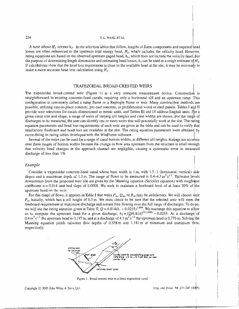
TRAPEZOIDAL BROAD-CRESTED WEIRS I The trapezoidal broad-crested weir (Figure I ) is a very common measurement device. Constructio is straightforward in existing concrete-lined canals, requiring only a horizontal sill and an upstream ramp. %his configuration is commonly called a ramp flume or a Replogle flume or weir. Many construction methods are possible, utilizing cast-in-place concrete, pre-cast concrete, or prefabricated wood or steel panels. Tables I a d I1 provide weir selections for canals dimensioned in metric units, and Tables I11 and IV address English units. r a given canal size and shape, a range of weirs of varying sill heights and crest widths are shown. For the rang of discharges to be measured, the user can identify one or more weirs that will potentially work at the site. The ra ing
curve-fitting to rating tables deweloped with the WinFlume software.
i discharge of less than 1 %. that velocity head changes in the approach channel are negligible, causing a
Consider a trapezoidal concrete-lined canal whose base width is 1 m, with 1.5 : 1 (horizontal: vertical) slopes and a maximum depth of 1.5 m. The range of flows to be measured is 0.4-4.5 m3 s-'. Tailwater le downstream from the proposed weir site are given by the Manning equation (Strickler equation) with rough coefficient n=0.014 and bed slope of 0.0008. We wish to maintain a freeboard level of at least 20% upstream head on the weir,
For this range of flows, it appears in Table I that weirs P,, Qm, or l7. may be satisfactory. We will choose {eir P, initially, which has a sill height of 0.5 m. We must check to be sure that the selected weir will meet he freeboard requirement at maximum discharge and remain free-flowing over the full range of discharges. To do so, we will use the rating equation given in Table 11, Q = 6.814(h1 + 0 . 0 2 5 5 ) ' . ~ ~ ~ . We rearrange this equation to all b w us to compute the upstream head for a given discharge, hl = ( ~ / 6 . 8 1 4 ) ( " ' . ~ ~ ~ ) - 0.0255. At a 0.4 m3 s-' the upstream head is 0.197 m, and at a discharge of 4.5 m3 s-' the upstream head is 0.776 Manning equation yields tailv~ater flow depths of 0.358 m and 1.181 m at minimum and respectively.
Figure 1. Broad-crested weir in a lined trapezoidal canal
Copyright 0 2005 John Wiley 8r Sons, Ltd. Irrig. and Drain. 54: 231-247 (20
SlMPLIFlED DESIGN OF FLUMES AND WEIRS I 235
Table I. Broad-crested ,weirs for lined trapezoidal canals dimensioned in metric units" I
Copyright Cc 2005 John Wiley & Sons, Ltd. Irrig. and Drain. 54: 23 I--247 (2005)
Canal shape Maximum Range of canal capacities Weir Weir shape canal selections
Side Bottom depthb d (m) LowerC Upper Crest width Sill height Minimum slopes width qInF qmyl bc P I (m) 1 h i d Z I b~ (m) (m s '1 (m s 1
Canal shape Maximum Range of canal capacities Weir Weir shape canal - selections
Side Bottom depthb d (m) LowerC upper Crest width Sill height Minim m slopes width Qmin Qmax bc (m) p l (m) ZI b~ (111) (m%-') (m3 s-') loss AH (m)
1.5 1.50 1.8 0.35 4.@ e m 2.75 0.417 0.051 0.38 6.5 R,n 3.00 0.500 0.05 0.43 8.1 Srn 3.50 0.667 0.49 6.6 T n 4.00 0.55 5.1 urn 4.50 1.000
aL8 2 H~,nax; Lb = 3 p l ; La + Lb > 2 to 3H1,,, 1, > 1.5H1,,,,, but within range given in Table I1 d > 1.2hl,,, +pl AH > 0.1 H I . bMa~imum recommended canal depth "Limited by sensitivity. d . . Lim~ted by Froude number; otherwise: limited by canal depth.
w k l a r Lb r L
Table 11. Rating equation parameters for broad-crested weirs in lined trapezoidal canals in metric units Q == K , (h l + K ~ ) " , where Q is discharge in m%-' and hl is upstream head in meters
b, ( m ) 1.00 1.20 1.20 1.40 1.60 I .80 I .50 i (iijj n A n n / * c <n n-.? n A.? n /" u..t~-u.ul U.JU-u. / J u..t~-v.uo 6.56-6.84 6.48-0.7i K1 2.226 3.640 3.751 4.070 4.217 4.35 1 5.007 K2 0.0083 0.0101 0.0126 0.0129 0.0088 0.0054 0.0193 U 1.898 1.815 1.841 1.824 1.751 1.685
At maximum flow, the upstream depth is the sum of the sill height and upstream head, 0.5 + 0.7'76 = 1.276 The required freeboard is 20% of 0.776m, or 0.155 m. The actual freeboard is the canal depth minus flow depth, or 1.5 - 1.276 = 0.224 m. This exceeds the required freeboard, so the freeboard is Table I shows that the required head loss for this weir is at least 0.052m. Thus, the allowable depth at maximum discharge is I .276 - 0.052 = 1.224 m. Since the actual tailwater depth is will flow free at maximum discharge. A similar check shows that the weir also flows discharge.
Copyright (0 2005 John Wiley & Sons, Ltd brig. and Drain. 5 4 23 1-247 (20 5 ) D I
SIMPLIFIED DESIGN OF FLUMES AND WEIRS 1 237
Table 111. Broad-crested weirs for lined trapezoidal canals dimensioned in English units" I
Ae! Be c e
De Ee D, Ee Fe
Ge He I, Je
Ke Je
Ke L, n/i, N e
p, Qe!
Re
s, Te
Qe
Re s, r, us v e
se Te u e
v, we
u e
v e
w e
x,
Canal shape IvIaximum Range of canal capacities Weir Weir shape canal selections
Side Bottom depthb d (ft) LowerC Upper Crest Sill slopes width Qrnin qlmy width height
Notes: "La 2 AH, ,,,,; Lb = 3p l ; L , + Lb > 2 to 3 Hllrlax L > 1.5 HI,,,,, but within range given in Table 111
Minimum head
d > 1.2hlxwax + P I AH > 0. IHI. - - - - - - - - - . b ~ a x i m u m recommended canal depth. 'Limited by sensitivity. %-' dLimited by Froude number; otherwise limited by canal depth. ~IL.L L~ A L i
ZI bl (ft) (ft3s-l) (ft s I) bc (ft) p, (ft) loss A H (ft)
The notes at the bottom of Table I are used to determine the lengths of the different approach distance from the staff gage to the start of the ramp should be at least equal to the length of 1 m is appropriate. The ramp length should be three times the sill height, or 1.5 should at least 1.5 times the maximum head and within the range shown in Table 11, so a
Copyright 0 2005 John Wiley & Sons, L.td. Irrig. and Drain. 54: 231-247 (2005)
238 T. L. WAHL ETAL. 1
Table IV. Rating equation parameters for broad-crested weirs in lined trapezoidal canals in English units Q = Kl (hl + where Q is discharge in ft3 s-' and h, is upstream head in feet
Parameters Weir A, Weir B, Weir C, Weir D, Weir E, Weir Fc Weir G, Weir
Figure 3. Long-throated flume with a rectangular throat section, constructed from concrete block 1
since the sill height affects the approach velocity and changes the rating of the structure. To use sill than those shown, the user may interpolate, using the data for an infinite sill height as a boundary. For velocity of approach is negligible.
The rating equation parameters in Tables Vand VI apply only when the gaging station is located in approach channel exactly the same width as the throat (e.g. Figure 2). If the head is measured wider earthen section, the approach velocity will be significantly lower and the rating must procedure for doing so is described in Clemmens et al. (2001), but it is generally simpler in such WinFlume computer program to model the structure.
Example I
is only 1 m wide, the range of
which appears to be a workable range.
flow, respectively. The freeboard at maximum discharge is 1.0 - 0.777 = 0.223 m, the flow depth, so there is adequate freeboard. The required head loss is the greater of the flow to discharge directly into the downstream trapezoidal section with an mum allowable tailwatei. level at maximum flow is the upstream depth
requirement to the larger of 0.046m or O.lH1. This 0.777 - O.l(O.577) = 0.7 I 9 m. At minimum flow, the The actual tailwater levels are lower than these limits, so the design is acceptable.
Copyright 0 2005 John Wiley & Sons, Ltd. Irrig. and Drain. 54: 2314247 (2005)
Table V. Rectangular-throated weirs and flumes for earthen channels, metric units
q = KI (111 + ~ 2 ) " where q is the unit dischage in m3 s-' per meter of throal widlh, and lzl is the sill referenced head in meters Q = q b ~ where Q is the total discharge in m3 s-I and h, is the throat width in meters
0.1 < h, < 0.21n,L = 0.2m 0.2 I b, < 0.3 ni: L = 0.35 m 0.3 b, 5 0.5 m, L = 0.5 m
Parameters pl = 0.05 m pl = 0.1 ~n PI = 03 PI = 0.1 m pl = 0.2m PI =03 pl = 0.1 ft p, = 0.21t PI = 03
KI 2.316 2.081 1.973 1.709 2.095 1.976 1.887 1.702 K2 0.003 0.003 0.003 0 0.004 0.0027 0 0 U 1.641 1.611 1.594 1.516 1.627 1.598 1.560 1.519 Itl, range 0.050-0.360 0.050-0.500 0.050-0.500 0.050-0.500 0.070-0.670 0.070-0.670 0.070-0.670 0.070-0.670 q, range 0.0 19-0.438 0.018-0.689 0.018-0.660 0.01 8-0.595 0.030-1.1 10 0.030-1.059 0.030-1.028 0.030-0.925 AH, m 0.028 0.048 0.063 0.4H1 0.046 0.066 0.086 0.4H1
b, 2 2.0 m, L = 1.5 m
Para~nelers yl = 0.2 ~n pl = 0.4m 17, = 0.6 m PI = a 3
KI 2.108 1.933 l.ti.54 1.677 K2 0.005 0.007 0.006 0 U 1.641 1.618 1.596 1.540 Ill , range 0.12-0.70 0.12-0.95 0.12--0.97 0.1-1.0 q, range 0.067-1.20 0.067-1.80 0.067--1.80 0.051-1.689 AH, m 0.053 0.092 0.1 22 0.4H1
La = 111 ,,,, and Lb = 2 to 3 times yl and L, + Lb = 2 to 3 times hl,,,. A H = O.lHI, or value lis~ed, whichever is greater, for flumes discharxing into a rectangular tailwater channel of the same width as the crest, 6,. A H = 0.4HI, or value listed, whichever is greater, for flumes with an abrupt expansion into a tailwater channel wider than the crest width: 6,.
SIMPL
IFIED
DE
SIGN
OF FL
UM
ES .4N
D W
EIR
S
Copyright 0
2005 John Wiley &
Sons, Lid.
Irrig. and Drain. 54: 23 -247 (2005)
!
242 T. L. WAHL ETAL. 1
The notes at the bottom of Tilble V help us determine the lengths of the flume gage to the start of the converging ramp is chosen to be 0.75 m (recognizing that H1 will be somewhat h,), the ramp length is 0.6m, and the control section length is 1 m. Downstream from this protection of the channel should be provided for a distance of about 2.5 m (four times the flow depth). Clemmens er al. (2001) provide more details about energy dissipation and erosion downstream from weirs and flumes.
WEIRS FOR CIRCULAR PIPES ~ Broad-crested weirs constructed in circular conduits make convenient portable and permanent measure ent structures. A bottom ramp leads to a flat crest whose height is generally 20-50% of the pipe diameter. The sill I height is chosen to limit the upstream flow depth to less than 90% of the pipe diameter. Figure 4 shows how to lay out the shape for the bottom ramp, which is a portion of an ellipse. These weirs are especially convenien for measurements in culverts, where they can be constructed in place, or pre-cast in the culvert before it is installe i l in the channel. Small, portable wl8rs can be created by installing a ramp and sill in a section of circular pipe s all enough to be moved from site to site. Adding leveling bubbles on top of the device facilitates an effec ive installation.
t Table VII provides weir selection and calibration data for different ratios of sill height to pipe diameter. The ata d are scaled in reference to the pipe diameter, with discharge ranges and rating equation coefficients appropriat for
metric or English units. The data in Table VII were developed by using WinFlume to analyze weirs of varying sill height in 1 ft and 1 m diameter pipes, assuming smooth concrete roughness for the ramp and sill. The user sc les the dimensions and discharge characteristics using relationships based on the concepts of Froude-scale model 1 ng. '
1 Small differences from the computed calibrations will occur when the results are scaled to other pipe sizes becquse
Uoslrearn ROW . I
Slalic pressure ..."
L-p:78$:: ' 0 4 L a > h , m & 'b= %,& 4 flow > h. -... .,,,-.
SIDE VIEW AND GENERAL LAYOUT
~.. Lavout 112 of minor and maior I , ~~....________.___..,....~-~~ v ads on ruler as shown her; - F(DD = 1 581 D, l i P l ~ - l i l 5h1,?
=& . Y , TOP VIEW
Y
END VIEW s l~d~ng polnts x and y along respecbve axis as indicated
Figure 4. Layout of ramp and sill for constructing a broad-crested weir in a circular pipe
Copyright 0 2005 John Wiley & Sons. Ltd. Twig. and D~zin. 54: 231-247 (2 I 05)
SIMPLIFIED DESIGN OF FLUMES AND WEIRS
Table VII. Weirs for circular pipes I
Note: The length values shown are minimum lengths in direction of Row, and may be increased 30% with only a slight change b calibration.
Metric units Length, diameter and sill height in meters, discharge in m3 s-'. Applicable to pipe diameters of 20 cm to 5 m
P I / D bc/D La /D & I D LID Range of hl / D Range of Q / D ' I ~ Kl K2
the roughness of the construction materials is not scaled. The practical limit on the scaling ratio is a fact r of about 5, allowing the data in Table VII to be used for pipe diameters ranging from 20 cm to 5 m and about 2. 1 inches to 5 ft while retaining a rating table uncertainty of about f 3%. For smaller of larger structures, one should develop a calibration using WinFlilme.
The discharge equation for a given pipe size is
U
where Q = discharge, m:'s-" or ft3 s-', D = diameter of pipe, m or ft, K1 =constant from Table VII, K2 constant from Table VII, h, =head measured from top of sill, m or ft and U = exponent. f Example I
Pregage distance, LPg 2 hman Sill height = p , Approach, La L hmax Dimensionless sill height =pIID Q=D2.5Kl@+&)" Converging, Lb = 3pI h,,i, = 0.070 Control, LC 2 1.50 - p l h,,, = [0.850 - p l ] AH = O.lH1 for weirs with a 6:l downstream transition ramp AH = 0.2HI for weirs with a vertical drop downstream from the crest AH = 0.4HI for weirs at the end of a pipe discharging into a wider downstream channel
We wish to construct a portable measuring device, like that shown in Figure 5, using a short diameter, circular steel pipe. We need to measure flows ranging from 2 to 40 1 s-' (0.002 to 0.04 m3
the pipe diameter will measure this range of flows. For that design, the rating equation is Table VII, we compute the range of Q I D ~ . ~ , which is 0.041-0.811. Table VII shows that only a sill
8 1.757 5 1.695 3 1.649
1.591 1.563 1.543 1.524
U
1.750 1.689 1.625 1.597 I .573 1.554 1.540
Copyright 0 2005 John Wiley & Sons, Ltd. Irrig. and Druin. 54: 23 1 247 (2005) t
T. L. WAHL ETAL. i
Figure 5. Example of a portable weir constl.ucted in a circular pipe I
V-SHAPED FLUMES I
When measuring flows in nalural channels or drainage canals, a structure that can measure a wide rang of discharges is often needed. Flumes with a V-shaped throat (Figure 6) are well suited to this task, since the effe tive throat width varies with the flow, providing good sensitivity over a wide discharge range. Flumes with V-sh ped throats can typically measure flows varying by a ratio of about 335 : 1. These flumes are typically constructed ith side slope angles that are mild enough to allow the use of flat-slab construction techniques.
Table VIII provides rating equations for V-shaped flumes with side slopes of 1 : 1 ,2 : 1, and 3 : 1. The base
i J
of the approach channel is assumed to be 0.6 m (2 ft), and the throat is elevated 0.15 m (0.5 ft) above the appr b"'" ach channel. This basic design should be suitable for a wide range of applications, in channels up to 1 m deep. For larger channels and flow rates. WinFlume can be used to develop a custom design. I
PORTABLE RBC FLUMES 1 A family of Cv'c srn;!I, por:&:le fiui-iles cslled R3C fliiiiies %ere desigiied fx iise iii f-i-rows and s~r~~lill channels (Ciemmens et al., 1984). These flumes are scale models of base width varies from 50 to 200 mm. Construction drawings showing with step-by-step assembly instructions and other details are given by Clemmens et al.
ZC Range of hl (m) Range of Q (m3 s-') KI K2 U Head loss,' AH($
bl = b2 = 0.60m - 2ft Approach length, L, = 0.90 m x 3 ft p , =p2 = 0.15m x 0.5i't Converging transition length, Lb = J .Om = 3.25 ft ZI =&=z2 Throat length, L = 1.2 m = 4 ft 0, = 0
ZC Range of h l (R) Range of Q (ft3 s-I) KI K2 U Head
1 0.25-2.70 0.063-28.3 2.214 0 2.563
'Head loss values shown as:iume gradual downstream expansion For an abrupt exprnsioninto a stagnant pool. AH = O.24H1. I
oss," AH(ft)
3.30
are commonly constru,cted from I -mm thick galvanized sheet metal. Fiberglass versions are also co)mmercially available at this time.
downstream end of the throat).
2 0.25-2.70 0.130-58.3 4.530 0 2.566 .22 or O.lH, 3 0.25-2.70 0.196-88.8 6.857 0 2.57 1 .19 or O.IHl
I
Subscripts: 1 denotes npstream channel. 2 denotes downstream channel. c denotes control section.
Figllre 7 . RBC flumes with center-mounted and side-mounted translocated stilling wells I
246 T. L. WAHL ETAL. 1 Table IX. RBC flumes I Throat width Throat length Head range Discharge range Head loss K1 K2 bc L hrnirl to hmax Qmin to Qmax AH
I
Metric units
mm mm mm I s-l mm Coefficients apply with Q in 1 s-' and h, in Lm
I
ft ft li gPm ft Coefficients apply with Q in gpm and h, i i ft
Conversions: 448.8 gals min-' (gpm.) = 1 ft3 s-'; 1000 I s-' = 1 m3 s-'. I
Table IX provides ranges of discharge and head for RBC flumes, along with rating equation parameters needbd to compute flow rates in metric or English units.
SUMMARY AND CONCLUSIONS ~ Long-throated flumes and broad-crested weirs are the most efficient, accurate, and adaptable critical-flow devicfs available for measuring discharge in open channels. A primary advantage is the fact that they can be calibrated by computer analysis, making the accurate rating of as-built structures possible and enabling the design of structur s 1 that meet unique site and operating requirements. For even more simplified application, precalibrated flume a d T weir designs have been presented here with tables that assist in their selection. In some cases (e.g. portable RqC flumes) devices can be selected directly from the tables with no additional calculations necessary. For permane t installations, the designer must verify that a selected structure will meet freeboard and allowable submergen e
construction techniques have also been illustrated.
i' criteria, and examples of these calculations have been given. Some of the many possible flume and wqir
I
REFERENCES i
Ackers P, White WR, Perkins JA, Harrison AM. 1978. Weirs and Fllcrves for- Flow Measurement. John Wiley & Sons: New York; 327 p p l Bos MG, Replogle JA, Clemmens AJ. 15'84. Flow Measuring Flumes for Open Clzar~nel S]lstenzs. John Wiley & Sons: New York: 321 pp. J
1
Copyright 0 2005 John Wiley & Sons, I Jd . Irrig. and Drain. 54: 23 1-247 (200 ) P
SIMPLIFIED DESIGN OF FLUMES AND WEIRS I 247
Bureau of Reclamation. 1997. Whter Measirrernent Manual, 3rd edn. US Government Printing Office: Washington, DC 204 2. Bureau of Reclamation. 2001. Water Measurement Manual, 3rd edn, revised reprint. US Government Printing Office: Washi gton, DC 20402. Clemmens AJ, Bos MG, :Replogle JA. 1984. Portable RBC-flumes for furrows and earthen channels. Transactions of the merican Society
of Agricult~~ral Engineers 27(4): 1016-1021, 1026. Clemmens AJ, Replogle JA, Bos MG. 1987. FLUME: A Computer Model for Estin~ating Flow Rates tlzrough Long-Throated M nsuring Flumes.
ARS-57. Agricultural Research Service, US Department of Agriculture, US Government Printing Office: Washington, D ; 64 pp. Clemmens AJ, Bos MG, 13eplogle JA. 1993. FLUME: Design and Calibration of Long-Throated Measurittg Fl~imes. ILR Publication 54,
International Institute for Land Reclamation and Improvement: Wageningen, The Netherlands; 123 pp.
for Land Reclamation and Improvement: Wageningen, The Netherlands; 382 pp.
McGraw-Hill: New York.
I Clemmens M, Wahl TL, Pos MG. Replogle JA. 2001. Water Measurement wit11 Flumes and Weirs. ILRI Publication 58, ~ntelmtional lnstitl~re
Replogle JA, Clemmens AJ, Pugh CA. 1999. Hydraulic design of flow measuring structures. In Hydraulic Design Handbook, Mays LW (ed.).
WahlTL, Clemmens AJ, Replogle JA, Bos MG. 2000. WinFlume-Windows-based software for the design of long-throated rqeasuring flumes. Fourth Decennial National Irrigation Symposium, American Society of Agricultural Engineers, 14-16 November 2000, Phoenix, Arizona. www.usbr.gov/prnts/hyd raulics~lab/winflume I
Copyright 0 2005 John Wi1e:y & Sons, Ltd, Irrig. and Drain. 54: 2311-247 (2005)