Page 1
8/13/2019 Standard Guide for Selection of Weirs and Flumes for Open-Channel Flow Measurement of Water
http://slidepdf.com/reader/full/standard-guide-for-selection-of-weirs-and-flumes-for-open-channel-flow-measurement 1/7
Designation: D5640 − 95 (Reapproved 2008)
Standard Guide for
Selection of Weirs and Flumes for Open-Channel FlowMeasurement of Water1
This standard is issued under the fixed designation D5640; the number immediately following the designation indicates the year of
original adoption or, in the case of revision, the year of last revision. A number in parentheses indicates the year of last reapproval. A
superscript epsilon (´) indicates an editorial change since the last revision or reapproval.
1. Scope
1.1 This guide covers recommendations for the selection of
weirs and flumes for the measurement of the volumetric flow
rate of water and wastewater in open channels under a variety
of field conditions.
1.2 This guide emphasizes the weirs and flumes for which
ASTM standards are available, namely, thin-plate weirs, broad-crested weirs, Parshall flumes, and Palmer-Bowlus (and other
long-throated) flumes. However, reference is also made to
other measurement devices and methods that may be useful in
specific situations.
1.3 The values stated in inch-pound units are to be regarded
as standard. The values given in parentheses are mathematical
conversions to SI units that are provided for information only
and are not considered standard.
1.4 This standard does not purport to address all of the
safety concerns, if any, associated with its use. It is the
responsibility of the user of this standard to establish appro-
priate safety and health practices and determine the applica-bility of regulatory limitations prior to use.
2. Referenced Documents
2.1 ASTM Standards:2
D1129 Terminology Relating to Water
D1941 Test Method for Open Channel Flow Measurement
of Water with the Parshall Flume
D3858 Test Method for Open-Channel Flow Measurement
of Water by Velocity-Area Method
D5242 Test Method for Open-Channel Flow Measurement
of Water with Thin-Plate Weirs
D5389 Test Method for Open-Channel Flow Measurement
by Acoustic Velocity Meter Systems
D5390 Test Method for Open-Channel Flow Measurement
of Water with Palmer-Bowlus Flumes
D5614 Test Method for Open Channel Flow Measurement
of Water with Broad-Crested Weirs
2.2 ISO Standard:3
ISO 555-1973: Liquid Flow Measurement in Open
Channels—Dilution Methods for Measurement of Steady
Flow—Constant-Rate Injection Method
3. Terminology
3.1 Definitions— For definitions of terms used in this guide,
refer to Terminology D1129.
3.2 Definitions of Terms Specific to This Standard:
3.2.1 blackwater— an increase in the depth of flow upstream
of a channel obstruction, in this case a weir or flume.
3.2.2 contracted weirs— contractions of thin-plate weirs re-
fer to the widths of weir plate between the notch and the
sidewalls of the approach channel. In fully contracted weirs,
the ratio of the notch area to the cross-sectional area of the
approach channel is small enough for the shape of the channelto have little effect. In suppressed (full-width) rectangular
weirs, the contractions are suppressed, and the weir crest
extends the full width of the channel.
3.2.3 crest— in rectangular thin-plate weirs, the horizontal
bottom of the overflow section; in broad-crested weirs and
flumes, the plane, level floor of the flow section.
3.2.4 critical flow— open-channel flow in which the energy,
expressed in terms of depth plus velocity head, is a minimum
for a given flow rate and channel.
3.2.4.1 Discussion— The Froude number is unity at critical
flow.
3.2.5 Froude number— a dimensionless number expressingthe ratio of inertial to gravity forces in free-surface flow. It is
equal to the average velocity divided by the square root of the
product of the average depth and the acceleration due to
gravity.
3.2.6 head— in this context, the depth of flow referenced to
the crest of the weir or flume and measured at a specified
1 This guide is under the jurisdiction of ASTM Committee D19 on Water and is
the direct responsibility of Subcommittee D19.07 on Sediments, Geomorphology,
and Open-Channel Flow.
Current edition approved Oct. 1, 2008. Published November 2008. Originally
approved in 1995. Last previous edition approved in 2003 as D5640 – 95 (2003).
DOI: 10.1520/D5640-95R08.2 For referenced ASTM standards, visit the ASTM website, www.astm.org, or
contact ASTM Customer Service at [email protected] . For Annual Book of ASTM
Standards volume information, refer to the standard’s Document Summary page on
the ASTM website.
3 Available from American National Standards Institute (ANSI), 25 W. 43rd St.,
4th Floor, New York, NY 10036, http://www.ansi.org.
Copyright © ASTM International, 100 Barr Harbor Drive, PO Box C700, West Conshohocken, PA 19428-2959. United States
1
Copyright by ASTM Int'l (all rights reserved); Thu Dec 19 11:37:29 EST 2013
Downloaded/printed by
Universidad Industrial De Santander Bucaramanga Columbia pursuant to License Agreement. No further reproductions authorized.
Page 2
8/13/2019 Standard Guide for Selection of Weirs and Flumes for Open-Channel Flow Measurement of Water
http://slidepdf.com/reader/full/standard-guide-for-selection-of-weirs-and-flumes-for-open-channel-flow-measurement 2/7
location; this depth plus the velocity head are often termed the
total head or total energy head.
3.2.7 hydraulic jump— an abrupt transition from supercriti-
cal to subcritical or tranquil flow, accompanied by considerable
turbulence or gravity waves, or both.
3.2.8 long-throated flume— a flume in which the prismatic
throat is long enough, relative to the head, for a region of
essentially critical flow to develop on the crest.
3.2.9 nappe— the curved sheet or jet of water overfalling a
weir.
3.2.10 notch— the overflow section of a triangular weir or of
a rectangular weir with side contractions.
3.2.11 primary instrument— the device (in this case, a weir
or flume) that creates a hydrodynamic condition that can be
sensed by the secondary instrument.
3.2.12 rangeability— the spread between the maximum,
Qmax , and minimum, Qmin, flow rates that a measuring
instrument can usefully and reliably accommodate; this may be
described as the ratio Qmax/Qmin.3.2.13 secondary instrument— in this case, a device that
measures the head on the weir or flume; it may also convert this
measured head to an indicated flowrate or could totalize the
flow.
3.2.14 subcritical flow— open-channel flow that is deeper
and at a lower velocity than critical flow for the same flow rate;
sometimes called tranquil flow.
3.2.14.1 Discussion— The Froude number is less than unity
for this flow.
3.2.15 submergence— the ratio of downstream head to up-
stream head on a weir or flume. Submergence greater than a
critical value affects the discharge for a given upstream head.3.2.16 supercritical flow— open-channel flow that is shal-
lower and at higher velocity than critical flow for the same flow
rate.
3.2.16.1 Discussion— The Froude number is greater than
unity for this flow.
3.2.17 throat— the constricted portion of a flume.
3.2.18 velocity head— the square of the average velocity
divided by twice the acceleration due to gravity.
4. Significance and Use
4.1 Each type of weir and flume possesses advantages and
disadvantages relative to the other types when it is consideredfor a specific application; consequently, the selection process
often involves reaching a compromise among several features.
This guide is intended to assist the user in making a selection
that is hydraulically, structurally, and economically appropriate
for the purpose.
4.2 It is recognized that not all open-channel situations are
amenable to flow measurement by weirs and flumes and that in
some cases, particularly in large streams, discharges may best
be determined by other means. (See 6.2.2.)
5. Weirs and Flumes
5.1 Weirs:
5.1.1 Weirs are overflow structures of specified geometries
for which the volumetric flow rate is a unique function of a
single measured upstream head, the other elements in the
head-discharge relation having been experimentally or analyti-
cally determined. Details of the individual weirs may be found
in the ASTM standards cited as follows:
5.1.2 Standard Weirs— The following weirs, for which
ASTM standards are available, are considered in this guide:5.1.2.1 Thin-plate weirs (see Test Method D5242).
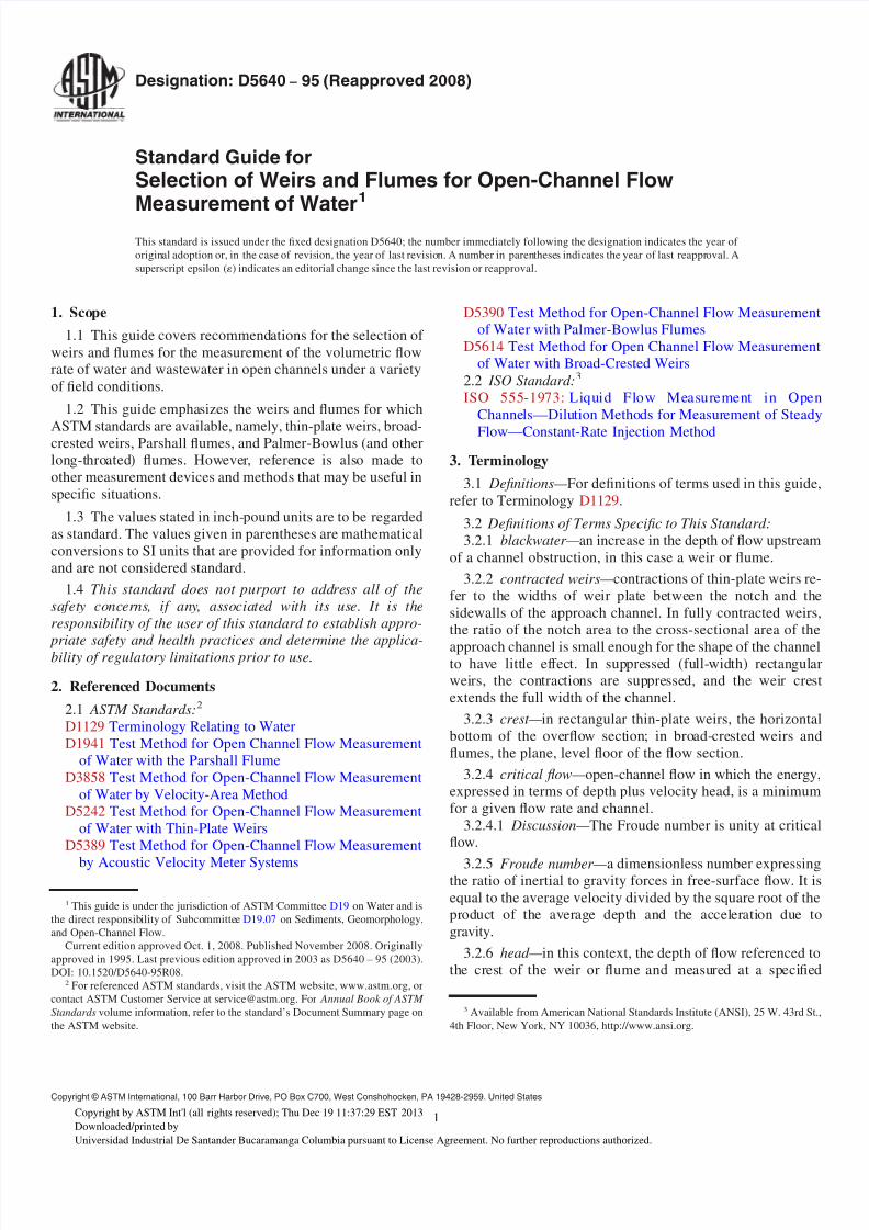
(1) Rectangular weirs (see Fig. 1).
(2) Triangular (V-notch) weirs (see Fig. 2).
5.1.2.2 Broad-crested weirs (see Test Method D5614).
(1) Square-edge (rectangular) weirs (see Fig. 3).
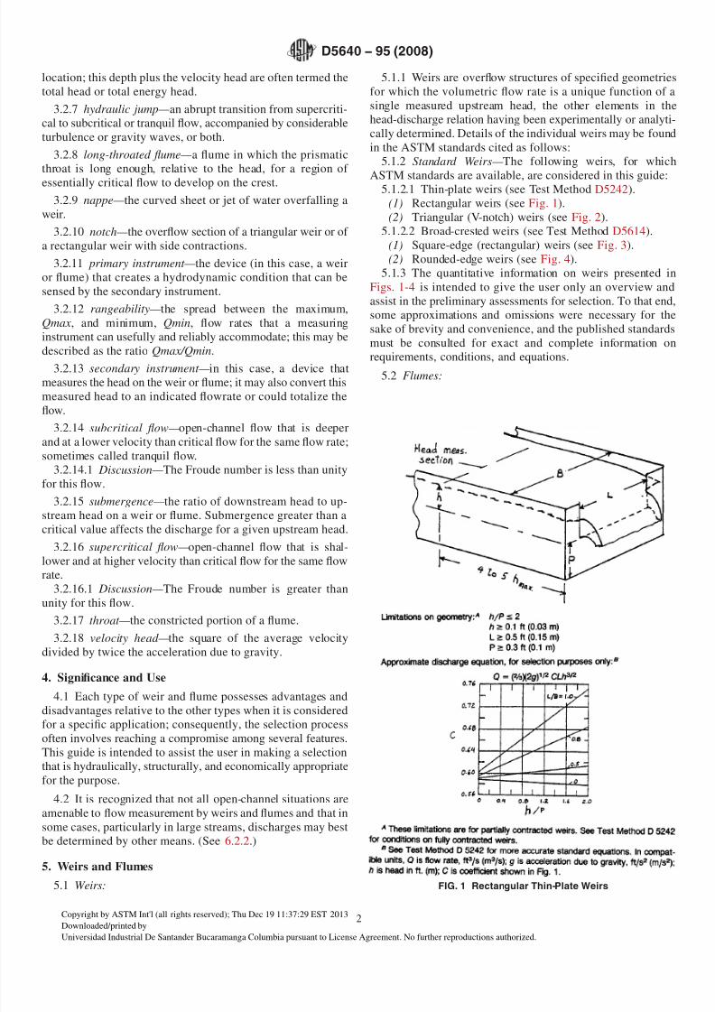
(2) Rounded-edge weirs (see Fig. 4).
5.1.3 The quantitative information on weirs presented in
Figs. 1-4 is intended to give the user only an overview and
assist in the preliminary assessments for selection. To that end,
some approximations and omissions were necessary for the
sake of brevity and convenience, and the published standards
must be consulted for exact and complete information on
requirements, conditions, and equations.
5.2 Flumes:
FIG. 1 Rectangular Thin-Plate Weirs
D5640 − 95 (2008)
2
Copyright by ASTM Int'l (all rights reserved); Thu Dec 19 11:37:29 EST 2013
Downloaded/printed by
Universidad Industrial De Santander Bucaramanga Columbia pursuant to License Agreement. No further reproductions authorized.
Page 3
8/13/2019 Standard Guide for Selection of Weirs and Flumes for Open-Channel Flow Measurement of Water
http://slidepdf.com/reader/full/standard-guide-for-selection-of-weirs-and-flumes-for-open-channel-flow-measurement 3/7
5.2.1 Flumes use sidewall constrictions or bottom shapes or
slopes of specified geometries, or both, to cause the flow to
pass through the critical condition; this permits determination
of the flow rate from a measured head and a head-dischargerelation that has been experimentally or analytically obtained.
Details of the individual flumes may be found in the ASTM
standards cited as follows:
5.2.2 Standard Flumes— The following flumes, for which
ASTM standards are available, are emphasized in this guide.
Other flumes, which may be useful in specific situations, are
cited in 5.2.4.
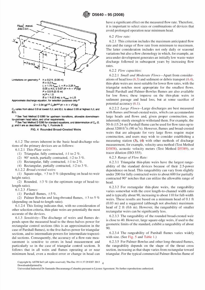
5.2.2.1 Parshall flumes (see Test Method D1941, Fig. 5, and
Table 1).
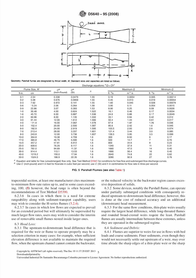
5.2.2.2 Palmer-Bowlus (and other long-throated) flumes
(see Test Method D5390 and Fig. 6).
5.2.3 The quantitative information on flumes presented in
Fig. 5 and Fig. 6 is intended to give the user only an overview
and assist in the preliminary assessments for selection. To that
end, some approximations and omissions were necessary for
the sake of brevity and convenience, and the published
standards must be consulted for exact and complete informa-
tion on requirements, conditions, and equations.
5.2.4 Other Flumes— The following flumes are not covered
by ASTM standards but are listed here because they were
developed for specific situations that may be of interest to users
of this guide. Detailed information on them can be found in the
reference section.
5.2.4.1 H-Series Flumes (1), (2) — This flume, which was
developed for use on agricultural watersheds, is actually a
combination of flume and triangular weir and consequentlyexhibits very high rangeability along with good sediment
transport capability.
5.2.4.2 Portable Parshall Flume (1) — This 3-in. (7.6-cm)
flume closely resembles the 3-in. standard Parshall flume with
the downstream divergent section removed. Its small size
makes it convenient to transport and install in some low-flow
field applications.
5.2.4.3 Supercritical-Flow Flumes (1) — These flumes were
developed for use in streams with heavy loads of coarse
sediment. The depth measurement is made in the supercritical-
flow portion of the flume rather than upstream.
6. Selection Criteria
6.1 Accuracy:
6.1.1 The error of a flow-rate measurement results from a
combination of individual errors, including errors in the
coefficients of the head-discharge relations; errors in the
measurement of the head; and errors due to nonstandard shape
or installation or other departures from the practices recom-
mended in the various weir or flume standards, or both. This
guide considers the accuracy of the primary devices only,
based on their accuracy potential under optimum or standard
conditions; from information included in the individual stan-
dards, users can estimate secondary-system errors and other
errors to obtain an estimate of the total measurement error.
FIG. 2 Triangular Thin-Plate WeirA
FIG. 3 Rectangular (Square-Edge) Broad-Crested Weirs
D5640 − 95 (2008)
3
Copyright by ASTM Int'l (all rights reserved); Thu Dec 19 11:37:29 EST 2013
Downloaded/printed by
Universidad Industrial De Santander Bucaramanga Columbia pursuant to License Agreement. No further reproductions authorized.
Page 4
8/13/2019 Standard Guide for Selection of Weirs and Flumes for Open-Channel Flow Measurement of Water
http://slidepdf.com/reader/full/standard-guide-for-selection-of-weirs-and-flumes-for-open-channel-flow-measurement 4/7
6.1.2 The errors inherent in the basic head-discharge rela-
tions of the primary devices are as follows:
6.1.2.1 Thin-Plate weirs:
(1) Triangular, fully contracted, 61 to 2 %.(2) 90° notch, partially contracted, 62 to 3 %.
(3) Rectangular, fully contracted, 61 to 2 %.
(4) Rectangular, partially contracted, 62 to 3 %.
6.1.2.2 Broad-crested weirs:
(1) Square-edge, 63 to 5 % (depending on head-to-weir
height ratio).
(2) Rounded, 63 % (in the optimum range of head-to-
length ratio).
6.1.2.3 Flumes:
(1) Parshall flumes, 65 %.
(2) Palmer Bowlus and long-throated flumes, 63 to 5 %
(depending on head-to-length ratio).6.1.2.4 This listing indicates that, with no consideration of
other selection criteria, thin-plate weirs are potentially the most
accurate of the devices.
6.1.3 Sensitivity— The discharge of weirs and flumes de-
pends upon the measured head to the three-halves power for
rectangular control sections (this is an approximation in the
case of Parshall flumes), to the five-halves power for triangular
sections, and to intermediate powers for intermediate trapezoi-
dal sections. Consequently, the accuracy of a flow-rate mea-
surement is sensitive to errors in head measurement and
particularly so in the case of triangular control sections. It
follows that in all weirs and flumes operating at or near
minimum head, even a modest error or change in head can
have a significant effect on the measured flow rate. Therefore,
it is important to select sizes or combinations of devices that
avoid prolonged operation near minimum head.
6.2 Flow rate:
6.2.1 This criterion includes the maximum anticipated flow
rate and the range of flow rate from minimum to maximum.
The latter consideration includes not only daily or seasonalvariations but also a flow chronology in which, for example, an
area under development generates an initially low waste-water
discharge followed in subsequent years by increasing flow
rates.
6.2.2 Flow capacities:
6.2.2.1 Small and Moderate Flows— Apart from consider-
ations of head loss (6.3) and sediment or debris transport (6.4),
thin-plate weirs are most suitable for lower flow rates, with the
triangular notches most appropriate for the smallest flows.
Small Parshall and Palmer-Bowlus flumes are also available
for low flows; these improve on the thin-plate weirs in
sediment passage and head loss, but at some sacrifice of
potential accuracy (6.1).
6.2.2.2 Large Flows— Large discharges are best measured
with flumes and broad-crested weirs, which can accommodate
large heads and flows and, given proper construction, are
inherently sturdy enough to withstand them. For example, the
50-ft (15.24-m) Parshall flume can be used for flow rates up to
about 3200 ft3 /s (90 m3 /s). However, flumes and broad-crested
weirs that are adequate for very large flows require major
construction, and users may wish to consider establishing a
measuring station (3), (4) with other methods of discharge
measurement, for example, velocity-area method (Test Method
D3858), acoustic velocity meters (Test Method D5389), or
tracer dilution (ISO 555).6.2.3 Range of Flow Rate:
6.2.3.1 Triangular thin-plate weirs have the largest range-
ability of the standard devices because of their 2.5-power
dependence on head. This rangeability can vary from slightly
under 200 for fully contracted weirs to about 600 for partially
contracted 90° notches that can utilize the allowable range of
head.
6.2.3.2 For rectangular thin-plate weirs, the rangeability
varies somewhat with the crest length-to-channel width ratio
and is typically about 90, increasing to about 110 for full-width
weirs. These results are based on a minimum head of 0.1 ft
(0.03 m) and a suggested (although not absolute) maximumhead of 2 ft (0.6 m). However, the rangeability of smaller
rectangular weirs can be significantly less.
6.2.3.3 The rangeability of the rounded broad-crested weir
is close to 40. However, large square-edge weirs, if used to the
geometric limits of the standard, exhibit a rangeability of about
90.
6.2.3.4 The rangeability of Parshall flumes varies widely
with size. (See Fig. 5 and Table 1.)
6.2.3.5 For Palmer-Bowlus and other long-throated flumes,
the rangeability depends on the shape of the throat cross
section, increasing as that shape varies from rectangular toward
triangular. For the typical commercial Palmer-Bowlus flume of
FIG. 4 Rounded Broad-Crested Weirs
D5640 − 95 (2008)
4
Copyright by ASTM Int'l (all rights reserved); Thu Dec 19 11:37:29 EST 2013
Downloaded/printed by
Universidad Industrial De Santander Bucaramanga Columbia pursuant to License Agreement. No further reproductions authorized.
Page 5
8/13/2019 Standard Guide for Selection of Weirs and Flumes for Open-Channel Flow Measurement of Water
http://slidepdf.com/reader/full/standard-guide-for-selection-of-weirs-and-flumes-for-open-channel-flow-measurement 5/7
trapezoidal section, at least one manufacturer cites maximum-
to-minimum flow-rate ratios up to, and in some cases exceed-
ing, 100; (5) however, the head range is often beyond the
recommendations of Test Method D5390.
6.2.3.6 In cases in which there is a need for extremerangeability along with sediment-transport capability, users
may wish to consider the H-series flumes (5.2.4).
6.2.3.7 In cases in which low flows are expected to prevail
for an extended period but will ultimately be superseded by
much larger flow rates, users may wish to consider the interim
use of removable small flumes nested inside larger ones.
6.3 Head Loss:
6.3.1 The upstream-to-downstream head difference that is
required for the weir or flume to operate properly may be a
selection criterion in many cases: for example, when sufficient
elevation difference is not available to maintain the required
flow, when the upstream channel cannot contain the backwater,
or the reduced velocity in the backwater region causes exces-
sive deposition of solids.
6.3.2 Some devices, notably the Parshall flume, can operate
under partially submerged conditions with consequently re-
duced upstream-to-downstream head difference; however, thisis done at the cost of reduced accuracy and an additional
(downstream) head measurement.
6.3.3 For the same flow conditions, thin-plate weirs usually
require the largest head difference, while long-throated flumes
and rounded broad-crested weirs require the least. Parshall
flumes are usually intermediate between these extremes, unless
they are operated in the submerged regime.
6.4 Sediment and Debris:
6.4.1 Flumes are superior to weirs for use in flows with bed
loads and coarse sediments. Finer sediments, even though they
would not necessarily settle out upstream of a weir, may over
time abrade the sharp edges of a thin-plate weir or the sharp
Discharge equations: AQ = Ch n
Flume Size, W C B
(Inch-Pound)C B
(SI) n
Maximum Q Minimum Q
ft-in. cm ft 3 /s m 3 /s ft 3 /s m 3 /s
0-1 2.54 0.338 0.0479 1.55 0.19 0.0054 0.005 0.000140-2 5.08 0.676 0.0959 1.55 0.45 0.013 0.019 0.00054
0-3 7.62 0.972 0.141 1.55 1.60 0.045 0.028 0.00079
0-6 15.24 2.06 0.264 1.58 3.90 0.11 0.054 0.0015
0-9 22.86 3.07 0.393 1.53 8.90 0.25 0.09 0.0026
1-0 30.48 4.00 0.624 1.522 16.1 0.46 0.17 0.0034
1-6 45.72 6.00 0.887 1.538 24.6 0.88 0.17 0.0049
2-0 60.96 8.00 1.135 1.550 33.1 0.94 0.42 0.012
3-0 91.44 12.00 1.612 1.566 50.4 1.43 0.61 0.017
4-0 121.9 16.00 2.062 1.578 67.9 1.92 1.26 0.036
5-0 152.4 20.00 2.500 1.587 85.6 2.42 1.6 0.045
6-0 182.9 24.00 2.919 1.595 103.5 2.93 2.6 0.074
7-0 213.4 28.00 3.337 1.601 121.4 3.44 3.0 0.085
8-0 243.8 12.00 3.736 1.607 139.5 3.95 3.5 0.099
10-0 304.8 19.38 4.709 1.6 300 8.50 6 0.17
12-0 365.8 46.75 5.590 1.6 500 14.2 7 0.20
15-0 457.2 57.81 6.912 1.6 800 22.6 8 0.23
20-0 609.6 76.26 9.117 1.6 1340 37.9 11 0.3125-0 762.0 94.69 11.32 1.6 1660 47.0 14 0.40
30-0 914.4 113.1 13.53 1.6 1890 56.4 16 0.45
40-0 1219.2 150.0 17.94 1.6 2640 74.8 22 0.62
50-0 1524.0 186.9 22.35 1.6 3280 92.9 27 0.76
A Equation and table for free (unsubmerged) flow only. See Test Method D1941 for conditions for free flow and submerged-flow discharge curves.B Use C (inch-pound) and h in feet for flowrate in cubic feet per second; use C (SI) and h in centimetres for flow rate in litres per second.
FIG. 5 Parshall Flumes (see also Table 1)
D5640 − 95 (2008)
5
Copyright by ASTM Int'l (all rights reserved); Thu Dec 19 11:37:29 EST 2013
Downloaded/printed by
Universidad Industrial De Santander Bucaramanga Columbia pursuant to License Agreement. No further reproductions authorized.
Page 6
8/13/2019 Standard Guide for Selection of Weirs and Flumes for Open-Channel Flow Measurement of Water
http://slidepdf.com/reader/full/standard-guide-for-selection-of-weirs-and-flumes-for-open-channel-flow-measurement 6/7
corner of a rectangular broad-crested weir and thus affect the
discharge coefficients.
6.4.2 When floating debris is present, the use of thin-plate
weirs, particularly those with triangular notches, should be
avoided.
6.4.3 In cases of exceptionally heavy loads of coarse sedi-
ment, users may wish to consider supercritical-flow flumes
(5.2.4). H-series flumes (5.2.4.1) also exhibit good sediment
passing behavior.
6.5 Construction Requirements:
6.5.1 This criterion takes into account the anticipated diffi-
culty and expense of constructing and installing a weir or flume
that meets standard specifications.
6.5.1.1 The Parshall flume is probably the most difficult to
construct, owing primarily to its relatively complex shape.
Also, the sharp downward slope of the throat may require some
excavation of the channel floor. Because the Parshall flume is
an empirical device, it is important to adhere closely to the
prescribed dimensions (see also 6.5.2).6.5.1.2 The difficulty in constructing thin-plate weirs arises
from the strict requirements for fabrication of the notch edges;
this difficulty can be expected to increase with weir size.
6.5.1.3 The shapes of the Palmer-Bowlus and other long-
throated flumes are often moderately complex, although less so
than those of the Parshall flume. However, their discharge
coefficients can be obtained theoretically, and consequently,
some departures from planned or prescribed dimensions can be
accommodated (see also 6.5.2).
6.5.1.4 Broad-crested weirs have relatively simple geometry
and are in principle perhaps the easiest to construct, particu-
larly when the existing channel is rectangular in cross section.
The rounded broad-crested weir, like the longthroated flumes,can be analyzed theoretically; the square-edge weir, on the
other hand, is empirical, and the square corner must be
carefully fabricated and maintained.
6.5.2 The commercial availability of prefabricated Parshall
and Palmer-Bowlus flumes is noted here. Sizes up to several
feet (metres) can be obtained, often in a form suitable for use
in sewer lines; the Palmer-Bowlus flumes are usually identified
by the diameter of the sewer into which they fit rather than by
throat width. Manufacturers’ literature should be consulted for
information on these and other flume and weir products.
Dimensions should be carefully checked.
6.6 Channel Conditions:
TABLE 1 Major (Approximate) Dimensions for Parshall Flumes (see also Fig. 5)A
Flume Size, W n n C F G N K E L
ft-in. cm ft cm ft cm ft cm ft cm ft cm ft cm ft cm ft cm ft cm
0-1 2.54 1.17 36 0.55 16.7 0.30 9.3 0.25 7.6 0.67 20.3 0.094 2.9 0.062 1.9 0.5–0.75 15–23 0.78 23.8
0-2 5.08 1.33 41 0.70 2 1.3 0.44 13.5 0.38 11.4 0.83 25.4 0.14 4.3 0.073 2.2 0.5–0.83 15–25 0.89 27.1
0-3 7.62 1.50 46 0.85 25.9 0.58 17.8 0.50 15.2 1.00 30.5 0.19 5.7 0.83 2.5 1.0–1.5 30–46 1.00 30.5
0-6 15.24 2.00 61 1.30 39.7 1.29 39.4 1.00 30.5 2.00 61.0 0.38 11.4 0.25 7.6 2.0 61 1.33 40.6
0-9 22.86 2.83 86 1.88 57.5 1.25 38.1 1.00 30.5 1.50 45.7 0.38 11.4 0.25 7.6 2.5 76 1.89 57.6
1-0 30.48 4.41 134 2.77 84 2.00 61 2.00 61.0 3.0 91 0.75 22.9 0.25 7.6 3.0 91 2.94 89.7
1-6 45.72 4.66 142 3.36 103 2.50 79 2.00 61.0 3.0 91 0.75 22.9 0.25 7.6 3.0 91 3.11 94.7
2-0 60.96 4.91 150 3.96 121 3.00 91 2.00 61.0 3.0 91 0.75 22.9 0.25 7.6 3.0 91 3.27 99.7
3-0 91.44 5.40 164 5.16 157 4.00 122 2.00 61.0 3.0 91 0.75 22.9 0.25 7.6 3.0 91 3.60 110
4-0 121.9 5.88 179 6.35 194 5.00 152 2.00 61.0 3.0 91 0.75 22.9 0.25 7.6 3.0 91 3.92 120
5-0 152.4 6.38 194 7.55 230 6.00 183 2.00 61.0 3.0 91 0.75 22.9 0.25 7.6 3.0 91 4.25 130
6-0 182.9 6.86 209 8.75 267 7.00 213 2.00 61.0 3.0 91 0.75 22.9 0.25 7.6 3.0 91 4.58 140
7-0 213.4 7.35 224 9.95 303 8.00 244 2.00 61.0 3.0 91 0.75 22.9 0.25 7.6 3.0 91 4.91 150
8-0 243.8 7.84 239 11.15 340 9.00 274 2.00 61.0 3.0 91 0.75 22.9 0.25 7.6 3.0 91 5.23 159
10-0 304.8 14.0 427 15.6 476 12.0 366 3.00 91.4 6.0 183 1.12 34.3 0.50 15.2 4.0 122 5.89 179
10-0 365.8 16.0 488 18.4 561 14.7 447 3.00 91.4 8.0 244 1.12 34.3 0.50 15.2 5.0 152 6.54 199
15-0 457.2 25.0 762 25.0 762 18.3 559 4.00 122 10.0 305 1.50 46.7 0.75 22.9 6.0 183 7.52 229
20-0 609.6 25.0 762 30.0 914 24.0 732 6.00 183 12.0 366 2.25 68.6 1.00 30.5 7.0 213 9.16 279
25-0 762.0 25.0 762 35.0 1067 29.3 894 6.00 183 13.0 396 2.25 68.6 1.00 30.5 7.0 213 10.79 329
30-0 914.4 26.0 792 40.4 1231 34.7 1057 6.00 183 14.0 427 2.25 68.6 1.00 30.5 7.0 213 12.43 379
40-0 1219.2 27.0 823 50.8 1548 45.3 1382 6.00 183 16.0 488 2.25 68.6 1.00 30.5 7.0 213 15.70 478
50-0 1524.0 27.0 823 60.8 1853 56.7 1727 6.00 183 20.0 610 2.25 68.6 1.00 30.5 7.0 213 18.97 578
A
For selection purposes only. See Test Method D1941 for complete standard dimensions and for information on upstream wingwalls and on locations for additional headmeasurement for submerged flow.
FIG. 6 Palmer-Bowlus and Other Long-Throated Flumes
D5640 − 95 (2008)
6
Copyright by ASTM Int'l (all rights reserved); Thu Dec 19 11:37:29 EST 2013
Downloaded/printed by
Universidad Industrial De Santander Bucaramanga Columbia pursuant to License Agreement. No further reproductions authorized.
Page 7
8/13/2019 Standard Guide for Selection of Weirs and Flumes for Open-Channel Flow Measurement of Water
http://slidepdf.com/reader/full/standard-guide-for-selection-of-weirs-and-flumes-for-open-channel-flow-measurement 7/7
6.6.1 Velocity Distribution:
6.6.1.1 Ideally, the velocity distribution just upstream of
weirs and flumes should approach that in a long, straight,
relatively smooth channel. Standards usually recommend the
length of straight approach channel needed to accomplish this
result; however, users should confirm the approach conditions
on a case-by-case basis. Where the water is relatively clear,
upstream baffles can be used to improve the velocity distribu-tion, provided they do not affect the head measurement.
6.6.1.2 In cases in which the ideal approach flow cannot be
attained, it is noted that flumes generally are affected less than
weirs by moderately skewed velocity distributions. Also, the
velocity distribution of the approach flow is less important
when this flow is of very low velocity.
6.6.2 Supercritical Flow— Weirs and flumes can be used in
supercritical-flow channels, provided that a hydraulic jump is
formed upstream so that the approach flow is subcritical. The
individual standards specify the upstream distance of the jump.
6.6.3 Channel Shape:
6.6.3.1 Rectangular approach channels are preferred for
thin-plate weirs, with exceptions for fully contracted weirs asdescribed in Test Method D5242; they are required for full-
width (or suppressed) rectangular weirs.
NOTE 1—Full-width rectangular thin-plate weirs require special provi-sion for aeration of the nappe.
6.6.3.2 Rectangular approach channels are required for
broad-crested weirs. However, this condition can be satisfied in
a non-rectangular channel by construction of vertical sidewalls
extending a prescribed distance upstream of the head measure-
ment location and with appropriate transitions as described in
Test Method D5614.
6.6.3.3 Circular channels (sewers) (see 6.5.2).
7. Secondary System
7.1 The requirements for head measurement and associated
instrumentation are basically similar for all weirs and flumes
and therefore are not considered among the selection criteria in
this guide. (An exception is the Parshall flume, which requires
an additional head measurement if used in the submerged
mode; other flumes and broad-crested weirs in some instances
may require downstream head monitoring to ensure unsub-
merged operation.) Refer to the individual standards for
secondary-system requirements.
7.2 The secondary measurement is a significant contributorto the total error of a flow measurement (see 6.1.1 and 6.1.3).
8. Keywords
8.1 flumes; open-channel flow; water discharge; weirs
REFERENCES
(1) Kilpatrick, F. A., and Schneider, V. R., “Use of Flumes in Measuring
Discharge,” Book 3, Chapter A14 of Techniques of Water-Resources
Investigations of the U.S. Geological Survey, 1983, pp. 1–46.
(2) “U.S. Agricultural Research Service, Field Manual for Research in
Agricultural Hydrology,” USDA Handbook 724, 1962, pp. 43–80.
(3) Carter, R. W., and Davidian, J., “General Procedure for Gaging
Streams,” Techniques of Water Resources Investigations of the U.S.
Geological Survey, Book 3, 1969, p. 7.
(4) Buchanan, T. J., and Somers, W. P., “Discharge Measurements at
Gaging Stations,” Techniques of Water Resources Investigations of the
U.S. Geological Survey , Book 3, Chapter A8, 1969, pp. 57–63.
(5) Grant, D. M., ISCO Open-Channel Flow Measurement Handbook , 3rd
Ed., 1989, pp. 40–46.
ASTM International takes no position respecting the validity of any patent rights asserted in connection with any item mentioned
in this standard. Users of this standard are expressly advised that determination of the validity of any such patent rights, and the risk
of infringement of such rights, are entirely their own responsibility.
This standard is subject to revision at any time by the responsible technical committee and must be reviewed every five years and
if not revised, either reapproved or withdrawn. Your comments are invited either for revision of this standard or for additional standards
and should be addressed to ASTM International Headquarters. Your comments will receive careful consideration at a meeting of the
responsible technical committee, which you may attend. If you feel that your comments have not received a fair hearing you should
make your views known to the ASTM Committee on Standards, at the address shown below.
This standard is copyrighted by ASTM International, 100 Barr Harbor Drive, PO Box C700, West Conshohocken, PA 19428-2959,
United States. Individual reprints (single or multiple copies) of this standard may be obtained by contacting ASTM at the above
address or at 610-832-9585 (phone), 610-832-9555 (fax), or [email protected] (e-mail); or through the ASTM website
(www.astm.org). Permission rights to photocopy the standard may also be secured from the ASTM website (www.astm.org/
COPYRIGHT/).
D5640 − 95 (2008)
7
Copyright by ASTM Int'l (all rights reserved); Thu Dec 19 11:37:29 EST 2013
Downloaded/printed by