5 AN OVERVIEW ON UTILIZATION OF NATURAL GAS COMBUSTION FLUE Chaerul Qalbi Am Energy Transport Phenomena Laboratory, Kookmin University, 77 Jeongneung-ro, Seongbuk-gu, Seoul 02707, Republic of Korea [email protected]ABSTRACT In this paper, a brief overview and comparison of methods to utilize the Natural Gas Combustion Flue stream. An increase in natural gas use as fuel and unique combustion characteristics call for specific waste heat optimization methods. Successful Natural Gas Combustion Flue Stream waste heat utilization methods exhibit certain phenomenons. From the overview, it is also discovered that the common waste heat method can be applied to natural gas combustion flue, although the specific condition is required. This paper divides the methods into three categories, non-contact heat exchanger, direct-contact heat exchanger, and thermoelectric generations. Result discussions of the performance are present as well as ideas for further studies that can be conducted to expand our scope of knowledge of the subject. Keywords: Natural gas, waste heat, heat exchanger, thermoelectric generator Received 18 February 2020 Accepted 6 June 2020 Available online 24 June 2020 INTRODUCTION Waste heat can come from anywhere, but an estimate of 71% of energy consumption lost is due to combustion and heat transfer processes [1]. Figure 1 shows the overall energy conversion distribution [1]. Engineer’s approach to this problem is to use cleaner fuel or energy sources and to utilize waste heat currently used in industries fully. Clean fuel-wise point of view, with our current technology, natural gas, and hydrogen, are the most efficient for its highest energy density. From power plants [2], district heating [3], manufacturing [4] to internal combustion engine [5], each sector uses natural gas as fuel and shows high efficiency performance-wise. However, waste heat within the process still exists. Research regarding how to properly use waste heat from combustion is becoming ubiquitous among scientists and engineers nowadays. The combustion characteristic of natural gas is that it needs excess air to reach the highest heat generation. Combined with the chemical composition of natural gas, it gives a result of high water vapor in the flue stream. Natural gas (NG) consists of multiple gas mixture, but a significant portion of it is methane, some analysis and simulation researches use this assumption to simplify the calculation process. With that assumption, the chemical reaction shown in Equation (1) [6]. 4 +2(2 + 3.762 ) → 2 +22 + (2− 1)2 + 7.522 (1) Table 1 and Table 2 show the chemical composition of NG and NG-fired boiler operating data, respectively [3]. When calculation simplification is not necessary, the chemical reaction is shown with Equations 2 and Table 3 [3]. The combination of Tables 1-3 and Equation 2 gives results in the chemical reaction shown in Equation 3. The comparison between with and without OISAA Journal of Indonesia Emas OISAA J. Indones. Emas, 3, 2020, 5-19
Transcript
5
AN OVERVIEW ON UTILIZATION OF NATURAL GAS COMBUSTION
FLUE
Chaerul Qalbi Am Energy Transport Phenomena Laboratory, Kookmin University, 77 Jeongneung-ro,
ABSTRACT In this paper, a brief overview and comparison of methods to utilize the Natural Gas Combustion Flue stream. An increase in natural gas use as fuel and unique combustion characteristics call for specific waste heat optimization methods. Successful Natural Gas Combustion Flue Stream waste heat utilization methods exhibit certain phenomenons. From the overview, it is also discovered that the common waste heat method can be applied to natural gas combustion flue, although the specific condition is required. This paper divides the methods into three categories, non-contact heat exchanger, direct-contact heat exchanger, and thermoelectric generations. Result discussions of the performance are present as well as ideas for further studies that can be conducted to expand our scope of knowledge of the subject. Keywords: Natural gas, waste heat, heat exchanger, thermoelectric generator
Received 18 February 2020 Accepted 6 June 2020 Available online 24 June 2020 INTRODUCTION Waste heat can come from anywhere, but an estimate of 71% of energy consumption lost is due to combustion and heat transfer processes [1]. Figure 1 shows the overall energy conversion distribution [1]. Engineer’s approach to this problem is to use cleaner fuel or energy sources and to utilize waste heat currently used in industries fully.
Clean fuel-wise point of view, with our current technology, natural gas, and hydrogen, are the most efficient for its highest energy density. From power plants [2], district heating [3], manufacturing [4] to internal combustion engine [5], each sector uses natural gas as fuel and shows high efficiency performance-wise. However, waste heat within the process still exists. Research regarding how to properly use waste heat from combustion is becoming ubiquitous among scientists and engineers nowadays.
The combustion characteristic of natural gas is that it needs excess air to reach the highest heat generation. Combined with the chemical composition of natural gas, it gives a result of high water vapor in the flue stream. Natural gas (NG) consists of multiple gas mixture, but a significant portion of it is methane, some analysis and simulation researches use this assumption to simplify the calculation process. With that assumption, the chemical reaction shown in Equation (1) [6].
Table 1 and Table 2 show the chemical composition of NG and NG-fired boiler operating data, respectively [3]. When calculation simplification is not necessary, the chemical reaction is shown with Equations 2 and Table 3 [3]. The combination of Tables 1-3 and Equation 2 gives results in the chemical reaction shown in Equation 3. The comparison between with and without
OISAA Journal of Indonesia Emas OISAA J. Indones. Emas, 3, 2020, 5-19
OISAA Journal of Indonesia Emas OISAA J. Indones. Emas, 3, 2020, 5-19
7
Table 3. Calculation of chemical compund in natural gas combustion process Compound Chemical Formula Mole Fraction Closed Formula
Methane CH4 x C x+2y+3z+4t+5u+6d+f
Ethane C2H6 y
Propane C3H8 z H 4x+6y+8z+10t+12u+14d
Butane C4H10 t
Pentane C5H12 u O 2f
Hexane C6H14 d
Nitrogen N2 e N 2e
Carbon dioxide CO2 f
Although, the quantity difference of water vapor in Equation 1 and 3 can be considered
small, in the actual application, the reaction happens in a massive portion, making it non-negligible. The existence of water vapor as a product of chemical reaction differentiates the produced heat into sensible and latent heat. These two kinds of heat can be optimized in different ways with a different set of equipment.
Waste heat utilization is every technology or method to be applied to any process to increase efficiency by using waste heat. Bruckner et al. [7] help classify waste heat utilization by its technologies shown in Figure 2. Active and passive depends on whether the heat is used directly at the same or lower temperature level or is transformed into another form of energy or to a higher temperature level. Waste heat utilization can also be classified from its feasibility, such as heat quantity, waste heat temperature, waste stream composition, and minimum allowable temperature.
Figure 2. Classification of waste heat method
OISAA Journal of Indonesia Emas OISAA J. Indones. Emas, 3, 2020, 5-19
8
However, these methods mentioned are applicable to all combustion flue instead of NG combustion flue. There are two conditions for a particular approach to be considered as NG combustion flue waste heat utilization. First is a specific modification to the system is made when NG combustion flue is applied, and the other is a unique phenomenon that happens as NG combustion flue stream flows along the process. FINDINGS AND DISCUSSION Methods and its mechanism following the definition of NG combustion flue waste heat utilization are discussed in this section. The three methods are Non-contact heat exchanger, Direct-contact heat exchanger, and Thermoelectric Genereator.
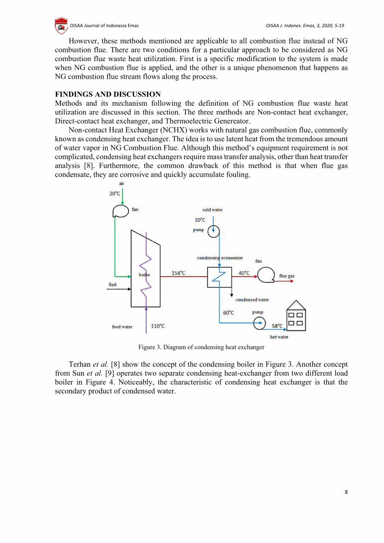
Non-contact Heat Exchanger (NCHX) works with natural gas combustion flue, commonly known as condensing heat exchanger. The idea is to use latent heat from the tremendous amount of water vapor in NG Combustion Flue. Although this method’s equipment requirement is not complicated, condensing heat exchangers require mass transfer analysis, other than heat transfer analysis [8]. Furthermore, the common drawback of this method is that when flue gas condensate, they are corrosive and quickly accumulate fouling.
Figure 3. Diagram of condensing heat exchanger
Terhan et al. [8] show the concept of the condensing boiler in Figure 3. Another concept
from Sun et al. [9] operates two separate condensing heat-exchanger from two different load boiler in Figure 4. Noticeably, the characteristic of condensing heat exchanger is that the secondary product of condensed water.
OISAA Journal of Indonesia Emas OISAA J. Indones. Emas, 3, 2020, 5-19
9
Figure 4. Diagram of system utilizing two doncensing heat exchangers
The result of NCHX is identical to a normal heat exchanger in terms of temperature
distribution that happened on the device, although to a certain degree. Figure 5 [8] shows the temperature of condensing heat exchanger, (Tfg-inlet = 158oC, Tfg-outlet = 40oC, Tcw-inlet = 10oC, Tcw-outlet = 60oC). From the 0-600m distance, the temperature contour is typical to a standard cross-flow heat exchanger, but after condensation starts, the temperature of cold water increases rapidly. Sun et al. [9] confirm that the existence of NCHX in the systems gives better performance through lower NG consumption and an estimate of a 52.7% increase in recovered heat. The total surface area to achieve this temperature is 80m2.
Figure 5. Tempereature distributiom of NCHX
Another thing to consider is the part shown in Figure 6 [8]. The marked area is one where
condensate will gather. This area is most likely damaged and accumulate fouling because of the condensation process. Both studies do not show any further treatment for treating the condensate from the flue gas or any condition on the condensate’s composition.
OISAA Journal of Indonesia Emas OISAA J. Indones. Emas, 3, 2020, 5-19
10
Figure 6. Location of condensation in the NCHX
The higher temperature rise is explained in Figure 5, due to the high portion of latent heat
in NG flue. Figure 7 shows the difference of heat characteristics of latent and sensible heat [3]. Unlike sensible heat, latent heat carries the same heat even though the temperature drops until the dew temperature of the flue gas.
Figure 7. Heat energy carried by the flue gas
The Direct Contact Heat Exchanger (DCHX) method also utilizes the latent heat of the flue
stream. The difference with the non-contact method, and this method is the heat transfer happens directly. This method eliminates the maintenance cost from corrosion and fouling from the non-contact method [10]. Moreover, direct interaction of the cold stream and the flue stream increase contact area for better heat transfer. The cold stream may use a unique solution, in the system uses Potassium Formate (KCOOH) [11], or water [10]. Figures 8 and 9 show the direct contact heat exchanger concept using Potassium Formate and water, respectively [11], [10]. It is apparent in the diagram that the direct contact heat exchanger symbol is unique with the sprayer symbol. The sprayer symbol indicates the spray valve to spread the working liquid during the process.
OISAA Journal of Indonesia Emas OISAA J. Indones. Emas, 3, 2020, 5-19
11
Figure 8. Diagram of DCHX system using Potasium formate in internal cycle
Figure 9. DCHX system using water connected to a separate district heating unit The critical aspect affecting DCHX effectiveness is the interaction of the working fluids.
Zhou et al. [10] manipulate the interactions of flue gas and water by increasing the mass flow rate of contact water; thus, the existence of water-gas mass ratio inside the DCHX at instance time increases. The increase of the water gas mass ratio of DCHX shows more heat is recovered. This heat recovered shown in Figure 10, the temperature difference at the terminal [10]. 5oC difference is much less than the conventional surface heat exchanger with the same volume level, this level of recovered heat equivalent to about 225 kW. Furthermore, pollutant emissions test results show no difference in Soot, SOx, and NOx between the entrance and exit of DCHX.
OISAA Journal of Indonesia Emas OISAA J. Indones. Emas, 3, 2020, 5-19
12
Figure 10. Effect of water-gas mass ration in DCHX
Simulations by Wang et al. [11] confirms these findings. Wang et al.’s simulation imposes
more interaction of working fluid and NG combustion flue by splitting (Figure 11) the amount of solution that supposed to enter the vapor generator into the DCHX part [11]. Through this modification, recovered heat increase up to 542 kW from 438 kW.
Figure 11. Modified system to gain more working fluid into the DCHX
Another further study to conduct is to discover the effect of nozzle shape has on heat
transfer of DCHX. Each nozzle shape works with a particular range of flows and generates different sizes of droplets. Zhou et al. [10] use a spiral nozzle shown in Figure 12 [10]. This specific nozzle shape is chosen because this shape helps reduce the blocking phenomenon that usually happens in a normal sprayer.
Figure 12. Side view of spiral nozzle
OISAA Journal of Indonesia Emas OISAA J. Indones. Emas, 3, 2020, 5-19
13
Another concept of DCHX is rotary regenerator. Nowadays, the rotary regenerator is known as Enthalpy Wheel (EW). EW works by making the hot stream and cold stream cross each other with a continuous rotating porous disk made from high heat capacity material [12]. Figure 13 shows the illustration of EW. The structure of the EW does not allow for high temperature, because the thermal expansion will deform the whole equipment and prevent rotation [13].
Figure 13. Enthalpy wheel concept
Performance of EW can be controlled with three aspects, EW radius, R, EW height, z, and
Rotating Speed, RS. The dimension of the EW determines how much of the NG combustion flue contact with the cold working fluid, as RS speed relates to how long both streams stay in contact.
Figure 14 shows possible setup to use NCHX and DCHX in one system [13]. Men et al. [13] replaced spray tower, usually meant to increase flue gas dew point temperature, with EW to recover enthalpy instead. The EW in the experiment uses a honeycomb pattern where the surfaces are covered with desiccant material to promote moisture transfer rate.
Figure 14. NG combustion flue waste heat utilization with NCHX and DCHX combination
The condensing heat exchanger performance is typical of the previous section. The key
parameter in the EW performance study is the Rotating Speed (RS). As shown in Figure 15 (a) temperature, (b) humidity ratio, (c) component efficiency, and (d) Overall efficiency, significantly changes with increasing RS of EW [13]. The most drastic changes are achieved when RS is more than 10rpm.
OISAA Journal of Indonesia Emas OISAA J. Indones. Emas, 3, 2020, 5-19
14
Figure 15. Performance of combination NG waste heat utilization system
One other consideration for waste heat utilization is that it is commonly used for heating
another working fluid, thus making it very susceptible to season and region. Thermoelectric generation (TEG) utilized the heat of the flue stream fully, so the need to make adjustments according to the season can be eliminated. An example of a TEG device as NG combustion flue waste heat utilization is illustrated in Figure 16 [14]. TEG device consists of two types of semiconductors with different Seebeck coefficients arranged in order. The device produces electrical potential when there is a temperature difference between the two surfaces. The flue gas stream works as the hot stream.
Figure 16. Thermoelectric generator concept
Other than temperature difference and Seebeck Coefficient, the performance of TEG is
dependent on the quantity, i, and dimension (module height, h, wide, w, and length, l) of the module. Typically, by coupling multiple units, it is possible to accumulate more power. Albeit its possibility, in the case of an electrical circuit, it is inevitable that the bigger the unit the higher its self-resistance.
OISAA Journal of Indonesia Emas OISAA J. Indones. Emas, 3, 2020, 5-19
15
Figure 17. Performance of TEG module
The module area determines the TEG utilization efficacy of waste heat into power
(electricity). It can be seen from Figure 17, the area of 0.18 m2 breaks the curve into two regions. The two different regions correspond with the condensation phenomenon found in NCHX. An area bigger than 0.18 m2 allows the NG combustion flue gas to condensate and give higher heat transfer, hence the higher power generated. However, as the module area reaches 0.74 m2, the self-resistance hinders power generation even though a large portion of heat still exists [14].
Figure 18. Humidification limit on TEG module Considering the large power generation under condensation effect Zhao et al. try to
humidify the flue stream, so the sensible heat used to gasify water, in other words, converting sensible heat into latent heat. Nonetheless, it can be seen in Figure 18, when the humidity ratio reaches 28 g/kg, temperature no longer changes [14]. It means water no longer evaporates yet the water vapor in the flue stream condenses into water.
OISAA Journal of Indonesia Emas OISAA J. Indones. Emas, 3, 2020, 5-19
16
Figure 19. Optimized design of TEG module
As the effect of humidification treatment on the generating performance is conditional, it
is necessary to compare both treated and untreated flue gas. For the comparisons, Figure 19 illustrates the concept for the intermediate model as a third condition [14]. The intermediate model utilizes the maximum heat from the untreated flue stream in the small module area and the treated flue stream where total humidification can be applied.
Figure 20. Power generation comparison of treated and untreated flue gas
The result of the comparisons is shown in Figure 20, proving that the intermediate model
generates the highest power [14]. The intermediate model can produce 21.2W with the module area of 0.65m2. This result is considered insignificant compared to other methods, but this number is in the form of electricity, so the heat recovered can instantly be applied to other kinds of energy. Nonetheless, until a much better material with a high Seebeck coefficient, this method may not be feasible for the industrial level.
OISAA Journal of Indonesia Emas OISAA J. Indones. Emas, 3, 2020, 5-19
17
Figure 21. Temperature distribution of TEG module
Further research can also try to discover the effect of TEG when coupled with fins or
modified into a curved surface. TEG performance is dependent on semiconductor skin temperature. Figure 21 shows the typical temperature distribution (Tf = Flue stream temperature, Tc = Cold stream temperature, Th = Hotter end of the module, Tl = Colder end of the module) of the TEG module [15]. With the existence of fins or curved surface modification on the TEG module, the heat transfer and skin temperature are expected to increases. However, the condensation phenomenon will show a different behavior, and a more complicated system for humidification is needed. Temperature distribution may be improved with fins or curved surfaces.
CONCLUSION All these three approaches to optimize waste heat from natural gas combustion is becoming ubiquitous among engineer all over the world. A full understanding of latent and sensible heat in the Natural Gas Combustion Flue Gas is essential. Therefore, more experimental data is also required. The summary of the overview is shown in Table 4. It is not appropriate to compare these methods, although it is possible with some comprehensive analysis [16]. However, each method performs under different condition, for different purposes and produce different by-products. Moreover, this paper only reviews the technical-wise methods while we know that even though technical calculation gives some excellent options, we still need to analyze them economically. Therefore, the decision of which methods to implement depends on the user.
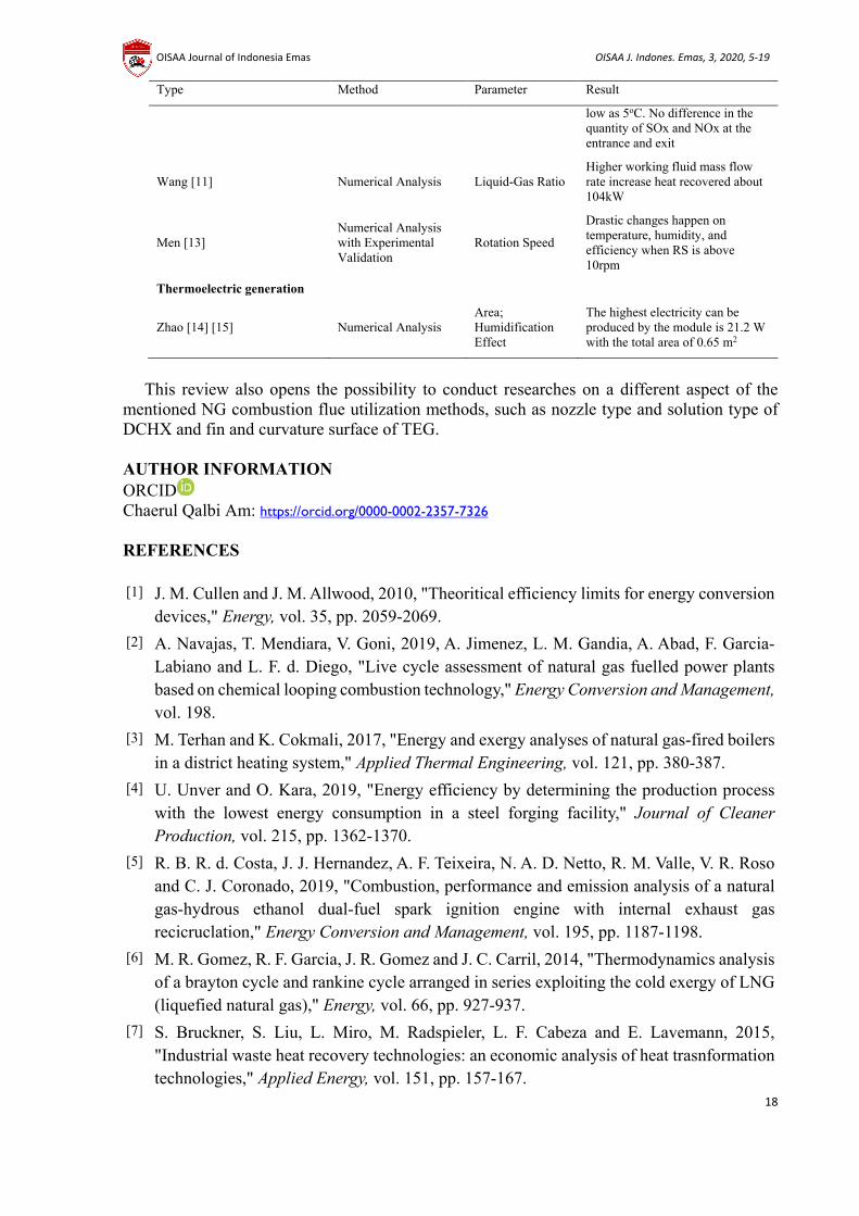
Table 4. Summary of utilization method Type Method Parameter Result
The highest electricity can be produced by the module is 21.2 W with the total area of 0.65 m2
This review also opens the possibility to conduct researches on a different aspect of the mentioned NG combustion flue utilization methods, such as nozzle type and solution type of DCHX and fin and curvature surface of TEG. AUTHOR INFORMATION ORCID Chaerul Qalbi Am: https://orcid.org/0000-0002-2357-7326 REFERENCES [1] J. M. Cullen and J. M. Allwood, 2010, "Theoritical efficiency limits for energy conversion
devices," Energy, vol. 35, pp. 2059-2069. [2] A. Navajas, T. Mendiara, V. Goni, 2019, A. Jimenez, L. M. Gandia, A. Abad, F. Garcia-
Labiano and L. F. d. Diego, "Live cycle assessment of natural gas fuelled power plants based on chemical looping combustion technology," Energy Conversion and Management, vol. 198.
[3] M. Terhan and K. Cokmali, 2017, "Energy and exergy analyses of natural gas-fired boilers in a district heating system," Applied Thermal Engineering, vol. 121, pp. 380-387.
[4] U. Unver and O. Kara, 2019, "Energy efficiency by determining the production process with the lowest energy consumption in a steel forging facility," Journal of Cleaner Production, vol. 215, pp. 1362-1370.
[5] R. B. R. d. Costa, J. J. Hernandez, A. F. Teixeira, N. A. D. Netto, R. M. Valle, V. R. Roso and C. J. Coronado, 2019, "Combustion, performance and emission analysis of a natural gas-hydrous ethanol dual-fuel spark ignition engine with internal exhaust gas recicruclation," Energy Conversion and Management, vol. 195, pp. 1187-1198.
[6] M. R. Gomez, R. F. Garcia, J. R. Gomez and J. C. Carril, 2014, "Thermodynamics analysis of a brayton cycle and rankine cycle arranged in series exploiting the cold exergy of LNG (liquefied natural gas)," Energy, vol. 66, pp. 927-937.
[7] S. Bruckner, S. Liu, L. Miro, M. Radspieler, L. F. Cabeza and E. Lavemann, 2015, "Industrial waste heat recovery technologies: an economic analysis of heat trasnformation technologies," Applied Energy, vol. 151, pp. 157-167.
OISAA Journal of Indonesia Emas OISAA J. Indones. Emas, 3, 2020, 5-19
[8] M. Terhan and K. Comakli, 2016, "Design and economic analysis of a flue gas condenser to recover latent heat from exhaust flue gas," Applied Thermal Engineering, vol. 100, pp. 1007-1015.
[9] F. Sun, J. Zhao, L. Fu, J. Sun and S. Zhang, 2017, "New district heating system based on natural gas-fired boilers with absorption heat exchangers," Energy, vol. 138, pp. 405-418.
[10] X. Zhou, H. Liu, L. Fu and S. Zhang, 2013, "Experimental study of natural gas combustion flue gas waste heat recovery system based on direct contact heat transfer and absorption heat pump," in ASME 2013 7th International Conference on Energy Sustainability, Minneapolis.
[11] Z. Wang, X. Zhang, J. Han and Z. Li, 2017, "Waste heat and water recovery from natural gas boilers: parametric analysis and optimization of a flue-gas-driven open absorption system," Energy Conversion and Management, vol. 154, pp. 526-537.
[12] H. S. Ray, B. P. Singh, S. Bhattacharjee and V. Misra, 2005, Energy in Minerals and Metallurgical Industries, pp. 225-226, India: Allied Publisher Private Limited, New Delhi.
[13] Y. Men, X. Liu, T. Zhang, X. Xu and Y. Jiang, 2019, "Novel flue gas waste heat recovery system equipped with enthalpy wheel," Energy Conversion and Management, vol. 196, pp. 649-663.
[14] Y. Zhao, S. Wang, M. Ge, Y. Li and Z. Liang, 2017, "Analysis of thermoelectric generation characteristics of flue gas waste heat from natural gas boiler," Energy Conversion and Management, vol. 148, pp. 820-829.
[15] Y. Zhao, S. Wang, Z. Liang and M. Ge, 2017, "Performance analysis of wet flue gas thermoelectric generator," in 9th International Conference on Applied Energy, Cardiff.
[16] X. Liang, X. Sun, G. Shu, K. Sun, X. Wang and X. Wang, 2013, "Using the analytic network process to determine method of waste energy recovery from engine," Energy Conversion and Management, vol. 66, pp. 304-311.
OISAA Journal of Indonesia Emas OISAA J. Indones. Emas, 3, 2020, 5-19