Issue no: 1 Page: 1 of 28 Date: 09 th May 2011 Authorised by: PON An unrivalled appliance to solve grease related problems Best Grease Trap in the World! Ref: Grease Shield™ AST 1850 Installation & Operations Manual – May 2011
Transcript
Issue no: 1 Page: 1 of 28 Date: 09th May 2011 Authorised by: PON
An unrivalled appliance to solve grease related problems
Issue no: 1 Page: 2 of 28 Date: 09th May 2011 Authorised by: PON
Table of Contents Amendment History ................................................................................................................... 4 Foreword .................................................................................................................................... 4 Terms & Definitions .................................................................................................................... 4 Section 1: Manufacturer’s Information ........................................................................................ 5
Contact Details: ...................................................................................................................... 5 Company Overview: ............................................................................................................... 5 Mission and Commitment to Quality ....................................................................................... 5 Standards & Certifications ...................................................................................................... 5
Section 2: Introduction ............................................................................................................... 6 Why do I need a GreaseShield? ............................................................................................. 6 GreaseShield System Overview ............................................................................................. 6
Section 3: Pre Installation .......................................................................................................... 8 Local codes and bylaws ......................................................................................................... 8 Applications: ........................................................................................................................... 8 Identification of Sources of FOG Ingress to sewers: ............................................................... 9 Locations of GreaseShield: .................................................................................................... 9 Electrical ...............................................................................................................................10 Hot Water ..............................................................................................................................10 Dimensions & Operational Requirements ..............................................................................10 Inlet Pipe work ......................................................................................................................10 Outlet Pipe work ....................................................................................................................10 Sizing & Selection of GreaseShield: ......................................................................................10 Handling Requirements .........................................................................................................11
Section 4: Installation ................................................................................................................12 Selection of Installer ..............................................................................................................12 Risk Assessments .................................................................................................................12 Method Statement: ................................................................................................................12 Insurances ............................................................................................................................12 Hot Water Connection ...........................................................................................................12 Inlet Pipe work ......................................................................................................................13 Outlet Pipe work ....................................................................................................................13 Electrical Connection ............................................................................................................13 Commissioning of Installation ................................................................................................13
Section 5: Operations – GreaseShield Daily Maintenance ........................................................14 General: ................................................................................................................................14 FOG Container: .....................................................................................................................14 Solids Container: ...................................................................................................................14 Staff Training .........................................................................................................................14 Chemical or other agents ......................................................................................................15 Disposal of intercepted substances .......................................................................................15
Issue no: 1 Page: 3 of 28 Date: 09th May 2011 Authorised by: PON
SECTION FIVE – TROUBLESHOOTING GUIDE .....................................................................16 No FOG collected in FOG Container .....................................................................................16 No Solids collected in Solids Container .................................................................................16 GreaseShield Overflows ........................................................................................................17 Water Around GreaseShield .................................................................................................17 Objectionable Odour .............................................................................................................18 Cleaning Cycles Not Working ................................................................................................18
SECTION SIX – SERVICING SCHEDULE ................................................................................19 Annual Service Requirements ...............................................................................................19 Selection of Trained Servicing Engineer ................................................................................19 Risk Assessments .................................................................................................................19 Method Statement: ................................................................................................................19 Insurances ............................................................................................................................19 Levels of Protection ...............................................................................................................19
Appendices ...............................................................................................................................20 Appendix 1: Dimensions, Installation & Service Requirements ..............................................20 Appendix 2: GreaseShield Sizing and Selection Calculation .................................................21 Appendix 3: GreaseShield Parts List .....................................................................................22 Appendix 4: Warranty ............................................................................................................24 Appendix 5: GreaseShield 1850 AST Statement of Conformity .............................................25
Issue no: 1 Page: 4 of 28 Date: 09th May 2011 Authorised by: PON
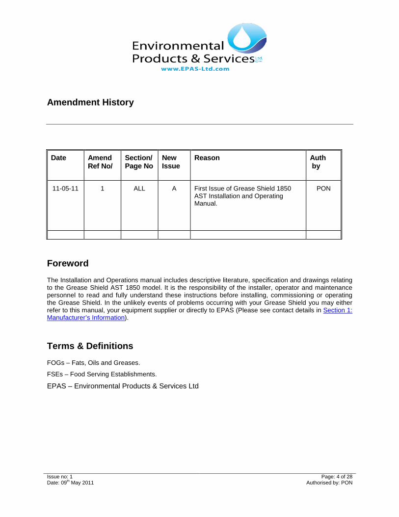
Amendment History
Date Amend Ref No/
Section/ Page No
New Issue
Reason Auth by
11-05-11
1
ALL
A
First Issue of Grease Shield 1850 AST Installation and Operating Manual.
PON
Foreword
The Installation and Operations manual includes descriptive literature, specification and drawings relating to the Grease Shield AST 1850 model. It is the responsibility of the installer, operator and maintenance personnel to read and fully understand these instructions before installing, commissioning or operating the Grease Shield. In the unlikely events of problems occurring with your Grease Shield you may either refer to this manual, your equipment supplier or directly to EPAS (Please see contact details in Section 1: Manufacturer’s Information).
Terms & Definitions
FOGs – Fats, Oils and Greases.
FSEs – Food Serving Establishments.
EPAS – Environmental Products & Services Ltd
Issue no: 1 Page: 5 of 28 Date: 09th May 2011 Authorised by: PON
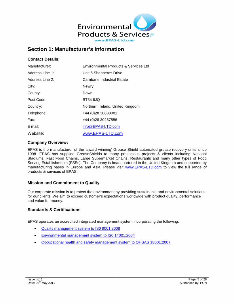
Website: www.EPAS-LTD.com Company Overview: EPAS is the manufacturer of the ‘award winning’ Grease Shield automated grease recovery units since 1998. EPAS has supplied GreaseShields to many prestigious projects & clients including National Stadiums, Fast Food Chains, Large Supermarket Chains, Restaurants and many other types of Food Serving Establishments (FSEs). The Company is headquartered in the United Kingdom and supported by manufacturing bases in Europe and Asia. Please visit www.EPAS-LTD.com to view the full range of products & services of EPAS.
Mission and Commitment to Quality Our corporate mission is to protect the environment by providing sustainable and environmental solutions for our clients. We aim to exceed customer’s expectations worldwide with product quality, performance and value for money. Standards & Certifications EPAS operates an accredited integrated management system incorporating the following:
• Quality management system to IS0 9001:2008
• Environmental management system to IS0 14001:2004
• Occupational health and safety management system to OHSAS 18001:2007
Issue no: 1 Page: 6 of 28 Date: 09th May 2011 Authorised by: PON
Section 2: Introduction
Why do I need a Grease Shield? FOGs cause major problems to privately & publicly owned drains and sewerage systems. FOGs are generated from practices carried out in FSEs and are usually disposed of down kitchen sinks or drains and can lead to the following problems:
• Reduced or blocked pipes leading to back flooding of premises and even pollution of natural watercourses.
• Malodours, unsanitary conditions and even closure of FSEs.
• Non Compliance with national/local authority’s discharge requirements & regulations.
• FOGs are extremely difficult for private & publicly owned Sewage Treatment Plants to treat and can lead to failure or unexpected and increased maintenance costs.
• FOGs can effect level instrumentation & pumps within pumping stations leading to operational failure and possible overflows.
• Loss of a potentially reusable resource when it enters the waste stream.
All of the problems are unnecessary because separating FOGs from waste water is easily accomplished by selecting, installing, operating & maintaining a Grease Shield correctly.
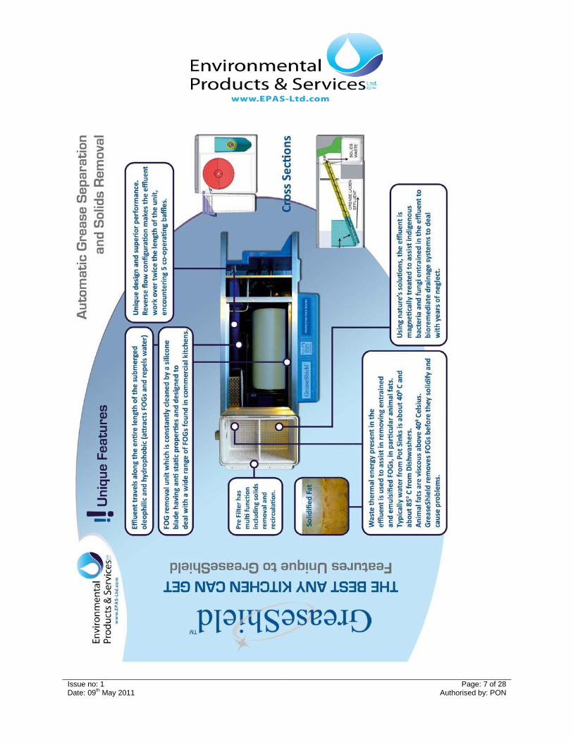
Grease Shield System Overview
• Effluent from Grease Producing appliances / Sinks enters the inlet/s of the Grease Shield.
• Food Solids get retained inside a hopper and get dewatered and removed to an external solids cartridge via an inclined auger.
• A number of co-operating Baffles and a Sudden Reverse Direction in the flow assist in retaining FOGs and helps to counteract emulsified contaminants.
• FOGs are removed by an Oleophilic (attracts oil) rotating drum.
• When the FOGs Container is attached to the Grease Shield, a rubber blade makes contact with the internal roller and allows the FOGs to be removed externally for recycling and safe disposal.
• The Grease Shield goes through automated recirculation feature to agitate and clean the tank followed by cleaning cycles to remove fine sedimentation and takes in water to back wash internal filters and prevent fouls smells.
• The Grease Shield has an anti flood pump that activates if the water level within the unit rises too high.
• All functions within the Grease Shield are controlled by a programmable logic controller (PLC).
• Treated effluent then flows under the outlet baffle and out to drain.
• Please refer to EPAS YouTube channel for further details: www.youtube.com/user/EPASLtd
Issue no: 1 Page: 7 of 28 Date: 09th May 2011 Authorised by: PON
Issue no: 1 Page: 8 of 28 Date: 09th May 2011 Authorised by: PON
Section 3: Pre Installation
Local codes and bylaws GreaseShields shall be selected in accordance with applicable plumbing, electrical and building codes, by-laws, and municipal ordnances. Applicable requirements can include the following:
• Maximum permissible FOG concentration in the FSEs effluent (typically between 100 and 300 mg/L);
• Mandatory maintenance requirements.
• Types of facilities required to have GreaseShields e.g: restaurants, fast food chains, supermarket, hotels, prisons, hospitals etc.
• Types of fixtures and appliances that are permitted to discharge wastewater through a Grease Shield;
• Minimum distances from plumbing fixtures;
• Venting requirements; and
• Flow control device restrictions and requirements.
• Location of GreaseShields in relation to food preparation areas.
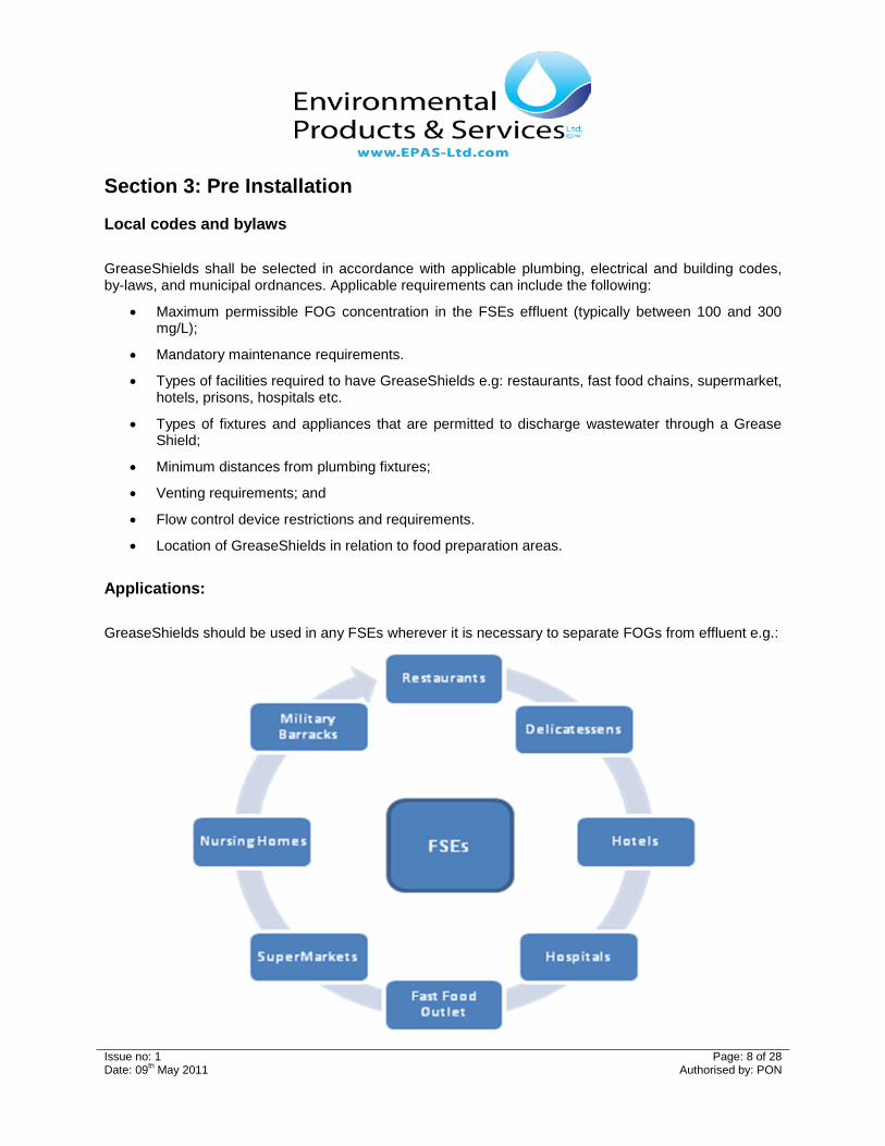
Applications: GreaseShields should be used in any FSEs wherever it is necessary to separate FOGs from effluent e.g.:
Issue no: 1 Page: 9 of 28 Date: 09th May 2011 Authorised by: PON
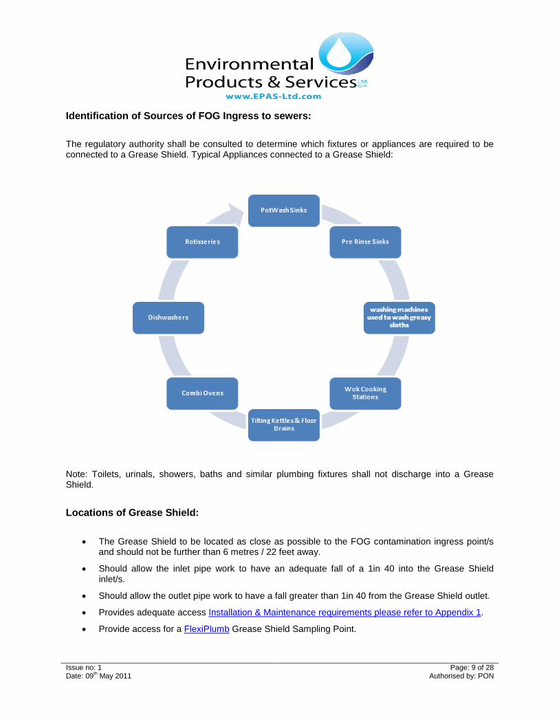
Identification of Sources of FOG Ingress to sewers: The regulatory authority shall be consulted to determine which fixtures or appliances are required to be connected to a Grease Shield. Typical Appliances connected to a Grease Shield:
Note: Toilets, urinals, showers, baths and similar plumbing fixtures shall not discharge into a Grease Shield.
Locations of Grease Shield:
• The Grease Shield to be located as close as possible to the FOG contamination ingress point/s and should not be further than 6 metres / 22 feet away.
• Should allow the inlet pipe work to have an adequate fall of a 1in 40 into the Grease Shield inlet/s.
• Should allow the outlet pipe work to have a fall greater than 1in 40 from the Grease Shield outlet.
Issue no: 1 Page: 10 of 28 Date: 09th May 2011 Authorised by: PON
• The Grease Shield is not intended for use outside of FSEs and may require sufficient external housing to protect it from the elements.
Electrical • An IP56 Socket with an operating Voltage of 230 Volts AC 13 Amp Plug is required to connect the
Grease Shield electrical plug into.
Hot Water • A ¾"BSP connection complete with isolation from a hot water supply to be located within 1 metre
of the Grease Shield location. The water pressure should not exceed 145 psi / 10 Bar and be not less than 4 psi/ 0.28 Bar.
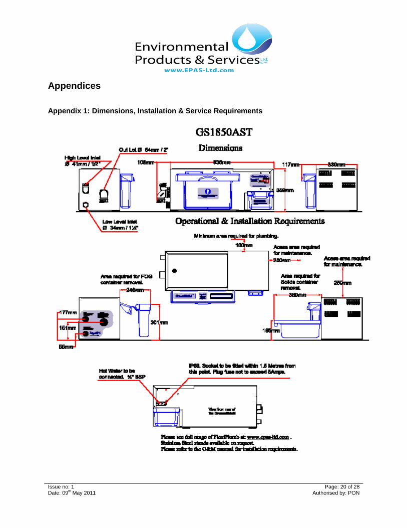
Dimensions & Operational Requirements
• Please refer to Appendix 1: Dimensions, Installation & Service Requirements for the GS AST 1850.
Inlet Pipe work
• The Installer shall be responsible for the design, supply, installation, testing and commissioning of the inlet pipe work. The Grease Shield is provided with FlexiPlumb EPDM hub-less couplings to allow various materials with different wall thickness to be connected to the inlet/s and outlet pipe work.
Outlet Pipe work
• The Installer shall be responsible for the design, supply, installation, testing and commissioning of the outlet pipe work. The Grease Shield is provided with FlexiPlumb EPDM hub-less couplings to allow various materials with different wall thickness to be connected to the inlet/s and outlet pipe work. N.B. A drain size of >50mm/2” is required to accept the 50mm/2” outlet piping of the Grease Shield.
Sizing & Selection of Grease Shield:
• Before purchasing & installing a Grease Shield a calculation is required to ensure correct sizing & selection for a trouble free installation.
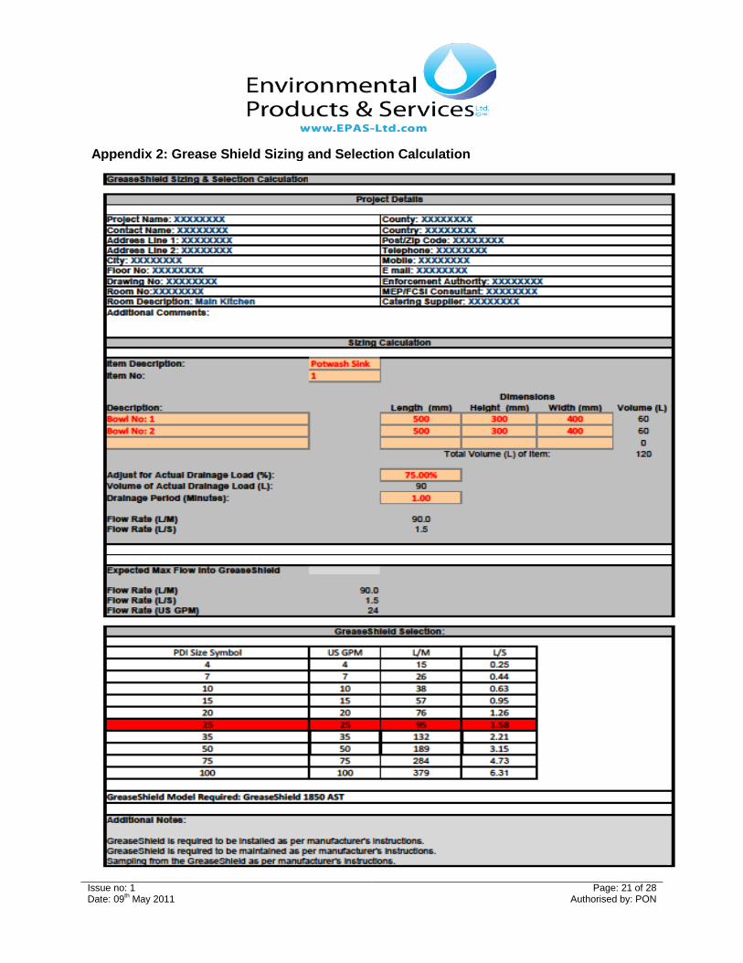
• The sizing calculation should be to determine the maximum or peak flow rate to be discharged through the Grease Shield and by reference to PDI G-101, ASME A112_14_3_2000 or CSA B481 Standards (Please refer to Appendix 2: Grease Shield Sizing & Selection calculation).
• The peak flow rate is determined by calculating the maximum amount of wastewater that can be discharged per minute or second through the Grease Shield. Peak flow rate shall be used as the basis for determining the minimum size of Grease Shield that is required. Peak flow rate shall be determined by:
o Actual drainage load from fixtures using the total discharge volume, which is based on the size, number of fixtures and expected drain down time into the Grease Shield.
o Determining the Max flow possible through the diameter of Inlet Piping into the Grease Shield.
o Appliance Manufacturer’s literature shall be consulted for the peak discharge rate.
Issue no: 1 Page: 11 of 28 Date: 09th May 2011 Authorised by: PON
• Choosing a Grease Shield with a flow rating larger than the expected peak flow rate will improve removal efficiency. GreaseShields that are rated for less than the expected peak flow rate should not be selected.
• Should you require additional information on sizing or selecting the appropriate Grease Shield model, please do not hesitate to contact your equipment supplier or directly to EPAS (Please see contact details in Section 1: Manufacturer’s Information).
Handling Requirements
• Adhere to all local & national Manual Handling Regulations to prevent injuries with safe lifting.
Issue no: 1 Page: 12 of 28 Date: 09th May 2011 Authorised by: PON
Section 4: Installation
Selection of Installer
• Where the service provider selected by the FSEs to install, commission & provide staff training on the Grease Shield/s is not the manufacturer of the equipment, the FSE should ensure that the service provider has been authorised by the manufacturer or deemed competent to do so.
Risk Assessments
• A Risk assessment should be carried out by the installer to prior to the installation to:
o Identify the hazards
o Decide who might be harmed and how
o Evaluate the risks and decide on precaution
o Record your findings and implement them
o Review your assessment and update if necessary
Method Statement:
• A Method Statement (safe system of work) should be completed by the installer to prior to the installation detailing the way a work task is to be undertaken:
o Identify the hazards
o Step by step guide on how to do the job safely.
o Control measures to be introduced to ensure the safety of anyone who is affected by the task.
Insurances
• It is highly recommended the installer has adequate coverage for Public & Employers Liability prior to the installation.
Hot Water Connection
• A ¾"BSP water intake hose has been provided - connect to the ¾"BSP fitting (solenoid valve) to the rear of the Grease Shield and then to the ¾"BSP fitting on the hot water supply. Switch on hot water supply. Note: the solenoid valve will not allow water into the Grease Shield until the unit is electrically connected.
• Check for any leaks & fix.
Issue no: 1 Page: 13 of 28 Date: 09th May 2011 Authorised by: PON
Inlet Pipe work 40mm/1.5” Inlet Piping
• The 40mm/1.5” Inlet is provided with a 40mm/1.5” FlexiPlumb Flow Controller.
• The inlet piping to the 40mm/1.5” Inlet must not be greater than 40mm/1.5”.
• The inlet piping must have a fall greater than 1in 40 into the Grease Shield.
• Straps or clips for supporting the inlet piping should be fixed about every 510mm (20”).
• Check for any leaks & fix.
32mm/1.25” Inlet Pipe Work
• The 32mm/1.25” Inlet is provided with a 32mm/1.25” FlexiPlumb 90 degree bend.
• The inlet piping to the 32mm/1.25” Inlet must not be greater than 32mm/1.25”.
• The inlet piping must have a fall greater than 1in 40 into the Grease Shield
• Straps or clips for supporting the inlet piping should be fixed about every 510mm (20”).
• Check for any leaks & fix.
Outlet Pipe work
• The 50mm/2” Outlet is provided with a 50mm/2” FlexiPlumb 90 degree bend.
• The Outlet piping from the 50mm/2” Outlet must not be reduced at any time.
• The outlet piping must have a fall greater than 1in 40 from the Grease Shield.
• Straps or clips for supporting the inlet piping should be fixed about every 510mm (20”).
• Check for any leaks & fix.
Electrical Connection
• Connect the Grease Shield electrical socket into the IP56 Socket provided.
Commissioning of Installation
• Ensure Grease Shield is removing FOGs
• Ensure Grease Shield is removing Solids
• Ensure Grease Shield can handle the flow rate.
• Ensure the Grease Shield has been installed correctly.
• Posters are available for download via www.EPAS-LTD.com or clicking in the following link: o Grease Shield Daily Maintenance o Best Management Practices o Daily Maintenance Log
• Please refer to EPAS YouTube channel for video on Grease Shield Daily Maintenance: o www.youtube.com/user/EPASLtd
• If there are any dirt/debris/liquids on or around the Grease Shield please remove and clean on a daily basis.
FOG Container:
• Empty & Clean FOG Container at least once daily. • Operational experience may require the FOG Container to be emptied and cleaned more than
once per day depending on quantities of FOG being removed. • Remove FOG Container & empty contents into a FOG Storage Container. • Record the amount of FOGs removed into a Daily Maintenance Log. • Clean & sanitise FOG Container & check for wear and tear. • Ensure wiper blade is clean & check for wear and tear. • Re attach FOG Container correctly to Grease Shield.
Solids Container:
• Empty & Clean Solids Container at least once daily. • Operational experience may require the Solids Container to be emptied and cleaned more than
once per day depending on quantities of Solids being removed. • Remove Solids Container & empty contents into Food Waste Collection Bin. • When the Solids Container, check & clean to ensure no solids has landed on the shelf & fallen to
the rear of the unit. • Record the amount of Solids removed into a Daily Maintenance Log. • Clean & sanitise Solids Container & check for wear and tear. • Locate Solids Container correctly to Grease Shield.
Staff Training
• To contribute to the goal of managing waste responsibly and minimizing the frequency of required cleaning and maintenance, the facility shall provide training to its employees in
o the proper function, operation and maintenance of GreaseShields; o the benefits of Best Management Practices within different locations within FSEs o the proper storage, handling, and disposal of wastes; o To obtain the maximum removal efficiency from a Grease Shield, facilities need to
establish and adhere to a regular schedule of cleaning and maintenance; and o Ensure that maintenance staff or external contractors follow the operating and
Issue no: 1 Page: 15 of 28 Date: 09th May 2011 Authorised by: PON
o Frequency of maintenance depends not only on the amount of FOG and Solids generated but on the facility’s implementation of Best Management Practices to reduce the FOG and Solids discharged into the sanitary sewer system.
o Signs should be posted in the kitchen, especially over the sinks & major FOG & solids contamination ingress points, informing staff what can and what cannot be poured down the drains.
Chemical or other agents
• An operator of a food services facility shall not use or permit the use of chemical agents, enzymes, bacteria, solvents, hot water, or other agents to facilitate the passage of FOG through a Grease Shield.
Disposal of intercepted substances
• FOGs & other intercepted substances removed from the Grease Shield shall be disposed of:
o in accordance with applicable regulations and bylaws;
o by a licensed waste hauler; and
o At a licensed waste disposal facility.
• Note: FOGs and Solids removed shall not be discharged into sanitary sewers, storm sewers, drainage ditches, or surface water.
Issue no: 1 Page: 16 of 28 Date: 09th May 2011 Authorised by: PON
SECTION FIVE – TROUBLESHOOTING GUIDE
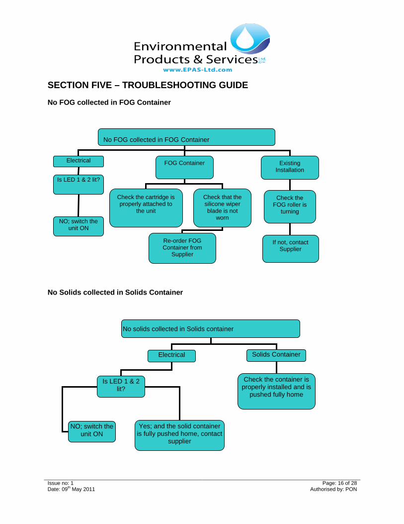
No FOG collected in FOG Container
No Solids collected in Solids Container
No FOG collected in FOG Container
FOG Container Existing Installation
Check the FOG roller is
turning
If not, contact Supplier
Check the cartridge is properly attached to
the unit
Check that the silicone wiper blade is not
worn
Re-order FOG Container from
Supplier
Electrical
Is LED 1 & 2 lit?
NO; switch the unit ON
No solids collected in Solids container
Solids Container
Check the container is properly installed and is
pushed fully home
Electrical
Is LED 1 & 2 lit?
NO; switch the unit ON
Yes; and the solid container is fully pushed home, contact
supplier
Issue no: 1 Page: 17 of 28 Date: 09th May 2011 Authorised by: PON
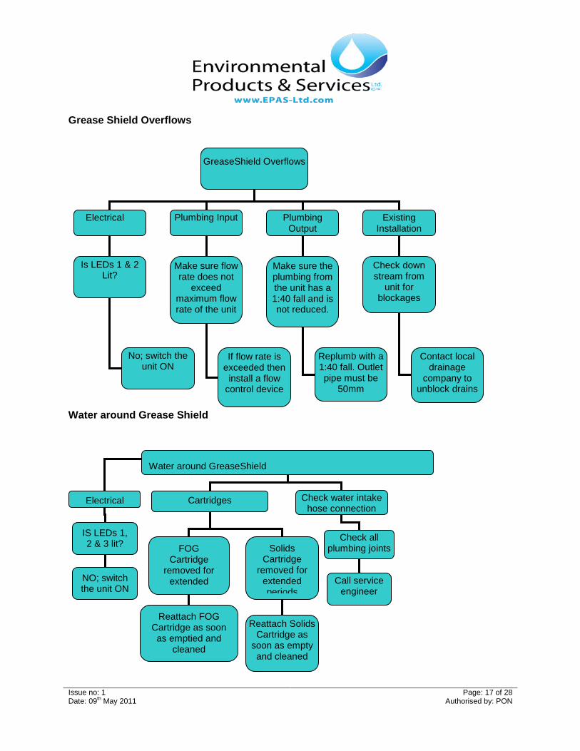
Grease Shield Overflows
Water around Grease Shield
Water around GreaseShield
Electrical Cartridges
Solids Cartridge
removed for extended periods
Reattach FOG Cartridge as soon as emptied and
cleaned
IS LEDs 1, 2 & 3 lit? FOG
Cartridge removed for
extended
NO; switch the unit ON
Reattach Solids
Cartridge as soon as empty and cleaned
Check water intake hose connection
Check all plumbing joints
Call service engineer
GreaseShield Overflows
Electrical
Plumbing Input Plumbing Output
Is LEDs 1 & 2 Lit?
No; switch the unit ON
Make sure flow rate does not
exceed maximum flow rate of the unit
If flow rate is exceeded then
install a flow control device
Make sure the plumbing from the unit has a 1:40 fall and is not reduced.
Replumb with a 1:40 fall. Outlet pipe must be
50mm
Existing Installation
Check down stream from
unit for blockages
Contact local drainage
company to unblock drains
Issue no: 1 Page: 18 of 28 Date: 09th May 2011 Authorised by: PON
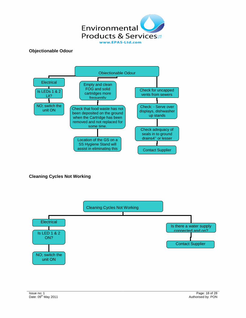
Objectionable Odour
Cleaning Cycles Not Working
Cleaning Cycles Not Working
Electrical
Is LED 1 & 2 ON?
NO; switch the unit ON
Contact Supplier
Is there a water supply connected and on?
Objectionable Odour
Contact Supplier
Electrical
Is LEDs 1 & 2 Lit?
NO; switch the unit ON
Empty and clean FOG and solid cartridges more
frequently
Check that food waste has not been deposited on the ground when the Cartridge has been removed and not replaced for
some time.
Location of the GS on a SS Hygiene Stand will
assist in eliminating this
Check for uncapped vents from sewers
Check: - Serve over displays, dishwasher
up stands
Check adequacy of seals in to ground drains4’’ or lesser
Issue no: 1 Page: 19 of 28 Date: 09th May 2011 Authorised by: PON
SECTION SIX – SERVICING SCHEDULE
Annual Service Requirements
• EPAS recommends that the Grease Shield 1850 AST is serviced by a trained and competent service engineer at least once annually. The purchaser should also check and comply with local codes and bylaws on mandatory maintenance requirements. If the FSE does not adhere to Best Management Practices this may require additional service visits per year, but this would be based on operational experience.
Selection of Trained Servicing Engineer • Where the service provider selected by the FSEs to service the Grease Shield is not the
manufacturer of the equipment, the FSE should ensure that the service provider has been authorised by the manufacturer or deemed competent to do so.
Risk Assessments • A Risk assessment should be carried out by the service provider to prior to works:
o Identify the hazards
o Decide who might be harmed and how
o Evaluate the risks and decide on precaution
o Record your findings and implement them
o Review your assessment and update if necessary
Method Statement: • A Method Statement (safe system of work) should be completed by the service provider to prior
to works detailing the way the work task is to be undertaken:
o Identify the hazards
o Step by step guide on how to do the job safely.
o Control measures to be introduced to ensure the safety of anyone who is affected by the task.
Insurances
• It is highly recommended the service provider has adequate coverage for Public & Employers Liability prior to works being undertaken.
Levels of Protection
• The Company recommends that before working with / on / or inside the Grease Shield it should be isolated from the power supply by disconnecting its electrical plug from the IP56 socket electrical supply.
Issue no: 1 Page: 20 of 28 Date: 09th May 2011 Authorised by: PON
Appendices
Appendix 1: Dimensions, Installation & Service Requirements
Issue no: 1 Page: 21 of 28 Date: 09th May 2011 Authorised by: PON
Appendix 2: Grease Shield Sizing and Selection Calculation
Issue no: 1 Page: 22 of 28 Date: 09th May 2011 Authorised by: PON
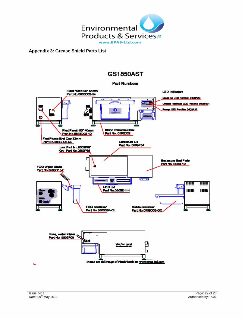
Appendix 3: Grease Shield Parts List
Issue no: 1 Page: 23 of 28 Date: 09th May 2011 Authorised by: PON
Issue no: 1 Page: 24 of 28 Date: 09th May 2011 Authorised by: PON
Appendix 4: Warranty EPAS warrants to the original user that the products manufactured by it delivered with this warranty shall be free from material defects in workmanship and materials for a period of 12 months from the date of invoice to the distributor (if sold by an authorised EPAS distributor) or the date of invoice to the purchaser (if sold directly by EPAS), but in no event longer than 15 months from date of shipment from EPAS production facility. Any claim must be made in writing promptly after discovery of the defect and within the applicable warranty period to the following: Manufacturer: Environmental Products & Services Ltd Address Line 1: Unit 5 Shepherds Drive Address Line 2: Carnbane Industrial Estate City: Newry County: Down Post Code: BT34 6JQ Country: Northern Ireland, United Kingdom Telephone: +44 (0)28 30833081 Fax: +44 (0)28 30257556 E mail: [email protected] Website: www.EPAS-LTD.com The product must be delivered, prepaid, to EPAS, together with proof of purchase, the serial number from which the item was removed and a return authorisation number issued by EPAS. If EPAS determines upon examination that the component is defective and that the warranty conditions are met, EPAS sole obligation under this warranty, and the purchaser’s sole and exclusive remedy, is the repair or replacement, at EPAS option, of the defective component, including parts and labour. The replacement will be furnished F.O.B. point of shipment. If EPAS determines that the component is not defective or that the other conditions of this warranty are not met, then any return of such part to the purchaser shall be at purchaser’s cost. This warranty shall not cover any defect in otherwise covered products resulting directly or indirectly from:
• failure to properly install, operate or maintain the product in accordance with EPAS instructions and procedures, including, without limitation, use in excess of rated flow, changing of operating programmes without EPAS permission, improper electrical service, use to remove emulsified fats and oils or use that fails to comply with applicable laws, regulations or codes;
• damage in transit, handling or installation; • modifications, adjustments, repairs, or alterations made by unauthorized persons; or • Other causes not arising out of defects in workmanship or materials.
EPAS shall not be responsible for damage to products resulting from vault flooding, sewer line back-up, pumping or lift station failure, ambient water flow or other sources of water damage. This warranty does not cover equipment or parts not manufactured by EPAS. Purchaser’s costs relating to any service, adjustment, removal, repair, packing, or otherwise incurred with respect to the defect prior to submission for warranty are the responsibility of purchaser. No distributor, sales person or other person is authorized to make any warranty statements on behalf of EPAS regarding EPAS products other than as set forth in this warranty. This statement of warranty supersedes any quote, brochure, or other statement or document with respect to warranty of EPAS products. Except as expressly set forth above, EPAS makes no representations, warranties or guarantees, either expressed or implied, including, without limitation, as to merchantability or fitness for a particular purpose, whether or not EPAS had knowledge of purchaser’s particular requirements or needs, or with respect to odour generation or other incidentals relating to use of the product. The sole and exclusive remedy with respect to this warranty any other claim relating to defects or any other condition or use of EPAS products, however caused, and whether such claim is based upon warranty, contract, tort, strict liability or any other theory, is LIMITED to the repair or replacement of the product, excluding labour or any other cost to remove or install said the product or, at EPAS option, repayment of the purchase price. In no event shall EPAS be liable, whether in contract, warranty, tort (including negligence), strict liability indemnity or any other legal theory, for incidental or consequential damages or for any other loss or cost of a similar type. Under no circumstances will the aggregate liability of EPAS for any cause of action related to the products covered hereby exceed the net purchase price received by EPAS for the products. Any action or suit by purchaser against EPAS relating to EPAS products must be brought within one (1) year of the date of the invoices referenced above. The exclusions and limitations set forth herein are separate and independent from any remedies which purchaser may have hereunder and shall be given full force and effect whether or not any or all such remedies shall be deemed to have failed of their essential purpose.
We hereby declare, under our sole responsibility, that the above machinery has been subject to the quality conditions of our registration to the BS EN ISO9001:2008 management standard and complies with the provisions of the following EC Directives:
• European Machinery Directive 2006/42/EC.
• Electromagnetic Compatibility Directive 2004/108/EC, amended by 93/68/EEC on the approximation of the laws of the Member States relating to electromagnetic compatibility.
• Low Voltage Directive 2006/95/EC amended by 93/68/EEC on the harmonisation of the laws of the Member States relating to electrical equipment designed for use within certain voltage limits.
• CE mark affixed 18th February 2005
Basis on which conformity is declared:
• The above machinery satisfies the relevant essential health and safety requirements of the European machinery Directive where appropriate.
• The above machinery complies with the protection requirements of the EMC Directive and the principal elements of the safety objectives of the Low Voltage Directive.
Standards Applied
• EN 61000-6-4:2001 Electromagnetic compatibility generic emission standard Part 2: Industrial Environment
• EN 6100-6-1:2001 Electromagnetic compatibility generic immunity standard Part 2: Industrial Environment
• EN 60204-1:2006, Safety of Machinery – Electrical Equipment of Machines