JOURNAL OF LIGHTWAVE TECHNOLOGY, VOL. 21, NO. 5, MAY 2003 1211
Analog Laser Predistortion for MultiserviceRadio-Over-Fiber Systems
L. Roselli, Senior Member, IEEE, V. Borgioni, F. Zepparelli, F. Ambrosi, M. Comez, P. Faccin, and A. Casini
Abstract—We have developed some low-cost predistortioncircuits to compensate second- and third-order laser distortionsin multiservice radio-over-fiber industrial systems. Depending onthe predistorter configuration implemented, average reductions of10–15 dB and of 8–10 dB have been observed in the laser second-and third-order distortions, respectively, within the cellular bandsrelevant to the European TETRA, GSM, and DCS standards.In particular, the development of the prototypes here illustratedis based on a new and original procedure that formalizes andsuitably integrates in a sinergistic way modeling, design, andexperimental activities.
Index Terms—Compensation, laser modeling, nonlinear distor-tion, predistortion, radio over fiber (RoF).
I. INTRODUCTION
WE describe here the development of low-cost broadbandcompletely analog predistortion circuits used to reduce
second- and third-order harmonic distortions (HD2 and HD3)and second- and third-order intermodulations (IM2 and IM3)of semiconductor lasers used in multiservice radio-over-fiber(RoF) industrial systems.
In RoF systems and networks, microwave and mil-limeter-wave multiplexed signals (briefly, RF signals) modulatean optical carrier generated by a semiconductor laser and aretransmitted from a central site through an optical fiber linkto the receiver, where a photodetector recovers the originalRF information (direct-detection systems). The RF signalscan then be distributed to home subscribers, as in the case ofcable television (CATV) [1], or radiated to mobile, nomadic,or fixed terminals like in cellular communication networks[2], [3]. Optical beamforming in phased-array antennas [4],[5], signal processing [6], [7], and EM-field remote sensing[8] represent other interesting examples of application of RoFtechniques. CATV distribution and GPRS, GSM/DCS, andTETRA microcellular networks are, in particular, the industrialapplications for which the study and development of the circuitshere illustrated have been committed.
In intensity-modulation direct-detection (IMDD) systems,the intensity of the optical carrier can be directly or externallymodulated by immediately driving the laser diode with the RF
Manuscript received September 30, 2002; revised January 28, 2003.L. Roselli, F. Zepparelli, and F. Ambrosi are with the Department of Elec-
tronic and Information Engineering, University of Perugia, I-06125 Perugia,Italy (e-mail: [email protected]).
V. Borgioni and M. Comez are with WIS S.r.l., I-06034 Foligno, Italy (e-mail:[email protected]).
P. Faccin and A. Casini are with Tekmar Sistemi S.r.l., I-48018 Faenza, Italy(e-mail: [email protected]).
Digital Object Identifier 10.1109/JLT.2003.810931
signal, or with the use of an additional electrooptical modulator,respectively.
The performances of the two solutions are typically compa-rable up to 10 GHz: the former becomes inefficient over a fewtens of gigahertz, mainly due to laser frequency relaxation [9]and chirping [10], [11] combined with the fiber chromatic dis-persion [12], but the latter suffers from higher distortion levels,due to the intrinsic nonlinearity of the modulators, and implieshigher losses, costs, and complexity. This is the reason why RoFsystems based on the direct modulation of semiconductor lasersrepresent nowadays a more mature and diffused technology forcommercial applications.
The performance of a direct IMDD scheme is strongly in-fluenced by the nonlinearity of the laser. When many RF sub-carriers are multiplexed together and modulate the light source,harmonic distortions and intermodulation products are gener-ated that influence negatively the quality of the signal at the re-ceiver [3]. If we consider some generic sinusoidal tones, ,and as the inputs of a nonlinear device, we will obtain at theoutput the following frequency components: ,where and are integer numbers that can assume thevalues 0, 1, 2, If two between and are simultaneouslynull, we have the harmonic components of a tone; if at least twoof them are different from zero, we talk of intermodulation prod-ucts. The sum defines the order of the harmonicsand of the intermodulations; then we can identify second-orderharmonic distortion (HD2) 2 , 2 , and 2 ; third-order har-monic distortion (HD3) 3 , 3 , and 3 ; second-order inter-modulation (IM2) ; and third-order intermodulation (IM3)
, , and . Some of these beats fall withinthe operational band where the original tones are allocated, thusyielding intraband distortion; it is important to note that in thoseRoF-systems, where the bandwidth of a single laser can be usedto allocate several services, there can be an interband negativeinfluence too due to the harmonics or intermodulations that,generated in a certain band, fall within that dedicated to anotherservice.
It should be also underlined that, up to now, fourth and higherorders have been typically considered as negligible because atvery low power levels, or well outside the operational bands.However, if the exactness of this assumption can be widelydemonstrated by classical CATV applications [1], [13], recentworks [14], [15] have pointed out that, especially with systemsmaking use of multicarrier standards like the Universal MobileTelecommunication System (UMTS), depending on the char-acteristics of the fiber link and/or of the amplifier adopted, alsofifth- and seventh-order products can affect negatively the usefulsignal. In this paper, we focus our attention mainly on second-and third-order components, due to their strong influence on the
1212 JOURNAL OF LIGHTWAVE TECHNOLOGY, VOL. 21, NO. 5, MAY 2003
systems taken into consideration; nonetheless, as will be clearerlater on, the principles of the approach described here can beextended to include also higher odd-order distortions in view ofa more general strategy of compensation.
To ensure a satisfying quality of the services released tothe users, it is mandatory to keep the distortions below certainlevels. Each service is characterized by its specific standard; forexample, analog video signals require distortion levels morethan 50 dB below that of the carrier to reach a carrier-to-noiseratio (CNR) around 45 dB and be imperceptible [1], [13]; inGSM picocellular and microcellular networks, a satisfyingCNR is given by values of the input dynamic range (DR)varying from 40–55 dB to 80–90 dB, respectively [2]; theUMTS standard requires an adjacent channel leakage powerratio of 45 dBc for the downlink and 33 dBc for the uplink[16], corresponding to values of the DR of about 30 dB. In anycase, this implies the realization of highly linear RoF systems.In view of large-scale productions, economical considerationssuggest the use of compensated low-cost lasers rather thanextremely linear but expensive devices. This implies the resortto compensation techniques that must be low-cost solutionsthemselves.
There are two major methods to reduce the nonlinear dis-tortions generated by lasers: feedforward compensation andpredistortion. The feedforward technique seems to be superiorbecause it also reduces the laser intensity noise [17]; however ithas a technoeconomical drawback represented by the fact thatit requires a greater number of components such as additionallaser diodes, a photodiode, and an optical coupler, resulting inhigher costs and complexity of the total system. Predistortioncan be a simpler approach since it implies only the insertionof an electronic predistorter somewhere in front of the lightsource to generate correcting frequency components equal inamplitude, but opposite in phase, to those undesired introducedby the laser nonlinearity. The problem of predistortion can beafforded in several ways. Predistortion blocks can be designedbased on Volterra models to invert the light-current charac-teristic curve of a laser operating in the CATV band up to500 MHz, thus compensating its nonlinearities [18]. Remark-able results have been obtained with adaptive predistortion:in [19], the compensation of an analog predistortion circuit ismaximized through the use of a microcontroller, thus reducingby 20 dB third-order intermodulations over the frequency range1750 1870 MHz. The same principles can be applied toexternally modulated lasers in RoF systems operating around10 GHz or more [20].
To keep costs and complexity as low as possible, being in-terested in industrializable prototypes, we have realized somecompletely analog predistortion circuits able to reduce about10-dB second- and third-order distortions of an entire class ofcommercial lasers, in the frequency range 3701980 MHz,over which CATV channels, up to more than 800 MHz, GPRS,GSM/DCS, and TETRA cellular communication bands can besimultaneously allocated. The predistorters are then virtuallysuited to multiservice RoF systems, the only limitation beingthe difference in the output power level typically requested toeach service. The development of these preindustrialized proto-types, illustrated through the following sections, is the yield ofthe sinergy of modeling, design, and experimental activities.
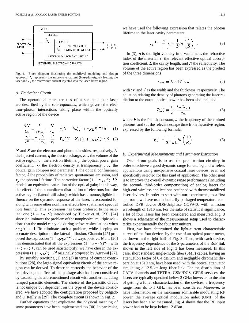
Following the scheme suggested by Sum and Gomes [21],shown in Fig. 1, as a basis for the design of a predistortion cir-cuit and to estimate its compensation capabilities, a laser circuitmodel has been previously developed and implemented into acommercial software package. In order to realize a predistorterable to correct the nonlinear behavior of an entire class of op-tical transmitters, a parameter extraction from a lot of four lasershas been performed, thus obtaining a laser circuit model with asort of average behavior.
The laser modeling and the subsequent parameter extractionprocedure are described in Section II.
Once having obtained a satisfying laser model, the nextstep has been the design of the predistorter. First, a suitableconfiguration has been selected and implemented; our choice fellon a “three-paths” predistorter reported in [22], suited to correctboth second- and third-order distortions. The behavior of sucha configuration has been optimized through computer-aideddesign (CAD) simulations, by exploiting, to this aim, thelaser model previously characterized. As a consequence ofthis CAD activity, a first prototype, suited to work within theaforementioned cellular frequency bands, has been realizedand subjected to an extensive experimental characterization.Several single-tone and two-tone tests have pointed out thebroadband functionality of the circuit: average 10–15 dB and8–10 dB compensations of the laser second-order (HD2 andIM2) and third-order (IM3) distortions, respectively, have beenobserved from the TETRA band (370 480 MHz) up to theDCS band (1710 1980 MHz). However, it is importantto note that the overall circuit behavior was not completelysatisfying: the nonlinear paths of the predistorter, devoted tocompensate second- and third-order distortions, have shown amutual spurious coupling, an effect not predicted by the CAD,that has practically prevented us from obtaining a simultaneouscorrection of the different kinds of distortions. Then, such aprocedure has been iterated: we have introduced and validatedsome modifications into the original predistorter configurationat the CAD and realized a new prototype. The first experimentalmeasurements have pointed out that such a new circuit cansimultaneously reduce laser HD2, IM2, and IM3 of about 12 dBand 6–8 dB, respectively, within the whole DCS frequencyband, thus allowing for the industrialization of the predistorter.
The design and development of these circuits are the subjectof Section III.
II. L ASER MODELLING
As outlined in the Introduction, the first steps toward the real-ization of the predistorter have been the development and exper-imental characterization of a semiconductor laser circuit modelable to reproduce the behavior of the class of industrial devicesto be compensated, namely, thermostabilized distributed feed-back (DFB) laser JDS/Uniphase CQF940, with emission wave-length of 1310 nm. Such a model has been implemented into thecommercial software package Agilent EEsof EDA AdvancedDesign System (ADS) and characterized through a parameterextraction procedure from the measurements relevant to a lot offour samples of the abovementioned class.
ROSELLI et al.: ANALOG LASER PREDISTORTION 1213
Fig. 1. Block diagram illustrating the multilevel modeling and designapproach.I represents the microwave current (bias-plus-signal) feeding thelaser andI the microwave current injected into the laser active region.
A. Equivalent Circuit
The operational characteristics of a semiconductor laserare described by therate equations,which govern the elec-tron–photon interactions taking place within the opticallyactive region of the device
(1)
(2)
and are the electron and photon densities, respectively,the injected current, the electron charge, the volume of theactive region, the electron lifetime, the optical power gaincoefficient, the electron density at transparency, theoptical gain compression parameter,the optical confinementfactor, the probability of radiative spontaneous emission, and
the photon lifetime. The corrective factor1models an equivalent saturation of the optical gain; in this way,the effect of the nonuniform distribution of electrons into theactive region (lateral diffusion), which has a nonnegligible in-fluence on the dynamic response of the laser, is accounted foralong with some other nonlinear effects like spatial and spectralhole burning. This expression has been preferred to the orig-inal one 1 introduced by Tuckeret al. [23], [24]since it eliminates the problem of the nonphysical multiple solu-tions that the model can yield during software simulations when
. To eliminate such a problem, while keeping anaccurate description of the lateral diffusion, Channin [25] pro-posed the expression1 , always positive. Mena [26]has demonstrated that all the expressions1 , with
, can be used satisfactorily; we have chosen the ex-pression 1 originally proposed by Agrawal [27].
By suitably rewriting (1) and (2) in terms of current contri-butions [28], the large-signal equivalent circuit of the active re-gion can be derived. To describe correctly the behavior of thereal device, the effect of the package also has been consideredby cascading the aforementioned circuit with another includinglumped parasitic elements. The choice of the parasitic circuitis not unique but dependent on the type of the device consid-ered; we have adopted the configuration proposed by Salgadoand O’Reilly in [29]. The complete circuit is shown in Fig. 2.
Further equations that explicitate the physical meaning ofsome parameters have been implemented too [30]. In particular,
we have used the following expression that relates the photonlifetime to the laser cavity parameters:
(3)
In (3), is the light velocity in a vacuum, the refractiveindex of the material, the relevant effective optical absorp-tion coefficient, the cavity length, and the reflectivity. Thevolume of the active region has been expressed as the productof the three dimensions
(4)
with and as the width and the thickness, respectively. Theequation relating the density of photons generating the laser ra-diation to the output optical power has been also included
(5)
where is the Planck constant, the frequency of the emittedphotons, and the relevant escape time from the active region,expressed by the following formula:
(6)
B. Experimental Measurements and Parameter Extraction
One of our goals is to use the predistortion circuitry inorder to achieve a good dynamic range for analog and wirelessapplications using inexpensive coaxial laser devices, even notspecifically selected for this kind of application. The other goalis to improve the overall dynamic range performance (includingthe second- third-order compensation) of analog lasers forhigh-end wireless applications equipped with thermostabilizedlaser devices. In order to start with our experiments, as a firstapproach, we have used a butterfly-packaged temperature-con-trolled DFB device JDS/Uniphase CQF940, with emissionwavelength of 1310 nm. For the sake of statistical significance,a lot of four lasers has been considered and measured. Fig. 3shows a schematic of the measurement setup used to charac-terize experimentally the four transmitters.
First, we have determined the light-current characteristiccurves of the four devices by the use of an optical power meter,as shown in the right half of Fig. 3. Then, with each device,the frequency dependence of the S-parameters of the RoF linkshown in the left side of Fig. 3 has been measured. In thiscase, short standard single-mode fiber (SMF) cables, having anattenuation factor of 0.4 dB/Km and negligible chromatic dis-persion at 1310 nm, have been used, with the optical attenuatorsimulating a 12.5-km-long fiber link. For the distribution ofCATV channels and TETRA, GSM/DCS, GPRS services, thelasers are typically operated below 2 GHz; however, to the aimof getting a fuller characterization of the devices, a frequencyrange from dc to 5 GHz has been considered. Moreover, tohave information on the maximum admissible modulating RFpower, the average optical modulation index (OMI) of thelasers has been also measured. Fig. 4 shows that the RF inputpower had to be kept below 12 dBm.
1214 JOURNAL OF LIGHTWAVE TECHNOLOGY, VOL. 21, NO. 5, MAY 2003
Fig. 2. Complete laser equivalent circuit. For the definition ofI , I , R , C , andV see [23], [24].
Fig. 3. Measurement setup used to characterize the lot of four lasersconsidered.
Fig. 4. Average measured laser OMI as a function of the input RF power.
In order to develop an industrializable prototype of the pre-distortion circuit, we have extracted the laser model parametersfrom the average curves of the lot. In particular, the procedurewe have followed, also with the aid of the optimization routinesof ADS, consisted of the following steps.
1) The measured average curves have been given as opti-mization goals to the simulator.
2) First-guess values have been assigned to the laser packageand active region equivalent circuit parameters.
3) The microwave coefficient frequency curve, whichis almost completely independent of the bias current, hasbeen used to extract the package parameters.
4) The microwave coefficient frequency curve, at thebias current mA, and the light-current curve havebeen used to extract the active region parameters.
5) Once a first satisfying agreement between measurementsand simulations has been obtained, a conclusive fine opti-mization has been performed by taking into considerationthe complete set of the measured curves as optimizationgoals, simultaneously.
Figs. 5 and 6 show the comparison between measured andsimulated average curves at the end of the optimization for twodifferent polarization currents mA and mA,respectively; in Table I, the final values of the parameters arelisted.
C. Nonlinear Distortion Prediction
With the values of the parameters of Table I, we have firstdetermined the and frequency curves for different biascurrents, always obtaining a good agreement with measure-ments (these curves are not shown here for the sake of brevity).Then we have tested the ability and accuracy of the model inreproducing the nonlinear behavior of the lasers. As an exampleof the results obtained, Fig. 7 shows the comparison betweenpredicted and measured HD2 and IM3 curves, averaged overthe four devices, at the bias values mA and mA.
III. PREDISTORERDESIGN AND DEVELOPMENT
Once having obtained an accurate laser circuit model, thefollowing step has been the development of the predistorter.The design and development procedure, consisting of CAD andexperimental activities, has been iterated until the realizationof a satisfying pre-industrialized prototype, as summarized byFig. 8.
ROSELLI et al.: ANALOG LASER PREDISTORTION 1215
Fig. 5. Laser circuit model parameter extractionI = 38 mA: comparisonbetween measurements (circles) and simulations (solid line) after theoptimization: (a) light-current curve; (b)S ; (c)S -modulus; (d)S -phase.
Fig. 6. Laser circuit model parameter extractionI = 50 mA: comparisonbetween measurements (circles) and simulations (solid line) after theoptimization: (a) light-current curve; (b)S ; (c)S -modulus; (d)S -phase.
TABLE IOPTIMIZED PARAMETER VALUES OF THELASER CIRCUIT MODEL
A. First Prototype: CAD
The solution adopted has been derived from a predistorterconfiguration presented in [22] and shown in Fig. 9. It is pos-sible to identify two main parts: a linear part and a nonlinearpart. The former simply consists of a time delay line, whilethe latter is further subdivided into second-order and third-orderpaths. Portions of the input RF signal are extracted to feed bothquadratic-law and cubic-law generators. The twocorrection signals, with magnitude and phase suitably adjusted
(a)
(b)
Fig. 7. (a) Laser HD2 and (b) IM3 product 2f � f : comparison betweenmeasured (solid line) and predicted (dashed line) curves of two typical valuesof the bias current,I = 38 mA (circles) andI = 50 mA (triangles). Inputsinusoidal tones with an RF power of 3 dBm have been used in both cases. Forthe intermodulation,f is variable andf = 815 MHz.
Fig. 8. Predistorter design and development procedure.
through a chain of shaping blocks, are then recombined withthe original delayed RF signal and sent to the laser. In this way,the circuit can simultaneously compensate HD2, HD3, IM2, andIM3 distortions.
Fig. 9 also suggests the possibility to extend the compensa-tion capability of this configuration simply by inserting higherorder paths and thus correcting, where needed, further sets ofdistortions, as for example the aforementioned fifth- and sev-enth-order IMs in UMTS systems.
1216 JOURNAL OF LIGHTWAVE TECHNOLOGY, VOL. 21, NO. 5, MAY 2003
Fig. 9. Schematic diagram of the first predistorter prototype.
To feed and recombine the linear and nonlinear paths ofthe predistorter, 10- and 3-dB splitters/combiners have beenimplemented.
The quadratic-law device can be realized with a couple ofdiodes in push–push configuration, fed with two 180shiftedinputs. To have a large operational frequency range, a differen-tial amplifier has been used to realize the input phase shift. Thecubic-law device can also be realized with a couple of diodes,but in push–pull configuration and with no input phase shift[31].
The function of the shaping chains is to generate correctionsignals having the same magnitudes but opposite phases, withrespect to the laser nonlinearities, in a frequency range as wideas possible. To this aim, two low-noise amplifiers (LNAs) havebeen inserted after the nonlinear generators to adjust the mag-nitude level of the drawn correction signals, which suffer anoverall attenuation of about 30 dB due to the input and outputsplitters and combiners; a fine control on the magnitude levelhas been assured by variable attenuators. Also a fine phase-ad-justment stage, to match the laser harmonic phase variations, hasbeen inserted in both the nonlinear paths. Finally, frequency-tiltshaping networks have been implemented to let the correctionsignals match the laser distortion curves in the whole opera-tional band. In practice, these are equalization filters, realizedby variable lumped passive components, having a frequency re-sponse that has to be suitably adjusted to follow exactly thetilt in the laser harmonic distortion frequency curves. In thisway, the correction band can be maximized and the same con-figuration of the predistorter can be adapted to different laserclasses or periodically retuned to prevent the variations due tothe laser aging. Concerning this point, it has to be noted thatthere are several undesired effects that can cause differencesin the behavior of devices part of the same class. Along withthe abovementioned laser aging, which gradually alters in timethe light power emitted, there can be a temperature-dependentshift of the threshold current; everything is then furtherly com-plicated by manufacturing tolerances that produce parametervalues spreading.
If the last aspect is generally the most difficult to face,several techniques are available to minimize the temperatureeffects and the laser aging. At present, there exist laser de-vices, as those taken into consideration in this paper, that arethermostabilized so as to practically eliminate such a problem:obviously this solution implies higher costs. Alternatively, onecan resort to simpler and cheaper, not stabilized, devices and
design the ancillary circuitry (like the predistorter, in this case)by inserting the temperature-dependence effect into the lasermodel used [32]. A similar scenario can be depicted for laseraging prevention: an automatic power control loop, enabledby an external photodiode, can be used to maintain constantaverage optical output power over laser-aging variations; toavoid cost enhancements, one can accept the laser aging whilecounteracting it with a programmed retuning of the electroniccircuitry, for example, through the periodical regulation of thecontrol voltages for the phase shifters and attenuators.
The laser model, as identified in Section II, has been cascadedto the predistorter described above and the whole subsystemsimulated. Fig. 10 summarizes the second-order distortion com-pensation procedure and the relevant results: first the correctionsignal has been suitably shaped in magnitude and phase, ex-ploiting the HD2 curves of the laser, over the whole operationalband, as shown in (a) and (b); then the HD2 and IM2 gen-eration of the predistorted laser has been compared with thatof the uncompensated laser. An average reduction of about10 dB in both (c) and (d) curves can be observed in the fre-quency range 0.4 2 GHz. It is important to remark herethat the broadband compensation of the HD2 yields automat-ically the optimum compensation of the IM2 too, since bothdistortions are generated by second-order nonlinearities withcomparable magnitude levels. The same considerations holdonly partly for third-order distortions: in fact, the correctionsignal, after being shaped with the aid of the HD3 curves, hasto be afterwards adjusted in magnitude to yield the maximumcompensation of the IM3 products. In particular, this is due tothe fact that IM3-difference products are typically generatedwith magnitude levels different from those of the HD3, andsuch a trend remains verified until the frequency spacing ofthe components forming the IM3 product is not very wide[12]. Fig. 11 shows the relevant results.
B. First Prototype: Realization and ExperimentalCharacterization
Based on the CAD results illustrated up to now, the first pro-totype of the predistorter shown in Fig. 12 has been realized.The configuration implemented has a simple architecture; mostof its components have cheap commercial counterparts; and nodigital or adaptive technique is used.
Even if the broadband functionality predicted by simulationspointed out the possibility of using a single predistorter for both
ROSELLI et al.: ANALOG LASER PREDISTORTION 1217
(a) (b)
(c) (d)
Fig. 10. Laser second-order compensation: higher graphs illustrate theshaping of the correction signal (diamonds), (a) magnitude and (b) phase,performed using the laser HD2 curves (solid line); lower graphs show acomparison between compensated (diamonds) and uncompensated (solid line)(c) HD2 and (d) IM2 productf + f . Input sinusoidal tones with an RF powerof 3 dBm have been used in both cases.
(a) (b)
(c) (d)
Fig. 11. Laser third-order compensation: higher graphs illustrate the shapingof the correction signal (diamonds), (a) magnitude and (b) phase, performedusing the laser HD3 curves (solid line); lower graphs show a comparisonbetween compensated (diamonds) and uncompensated (solid line) (c) HD3 and(d) IM3 product2f � f . Input sinusoidal tones with an RF power of 3 dBmhave been used in both cases.
Fig. 12. First prototype of the predistorter.
CATV and cellular communications, the difference among thepower levels typical of the two breeds of service has forced usto specialize the circuit for one of them. The prototype then hasbeen realized with the aim of improving the quality of servicein TETRA, GSM/DCS, and GPRS RoF networks.
The prototype has been subjected to an extensive exper-imental characterization; several single-tone and two-tonetests have been performed to check the effectiveness of thecompensation. Fig. 13 shows the relevant measurement setup.Single-tone tests have been performed by means of the har-monic measurement tool of a network analyzer HP 8753, whoseoutput tone, suitably filtered and with a 12-dBm RF power,fed the predistorter. The cascaded laser to be compensated hasbeen biased with a current of 51 mA; since about 3 dB are lostthrough the predistorter, the actual RF power entering the laserwas 9 dBm, a value corresponding to an OMI of about 40%,as can be seen in Fig. 4. The optical attenuator has been set tosimulate again a 12.5-km-long fiber link. The HD2 and HD3frequency curves have been finally recorded by the networkanalyzer.
For two-tone tests, the RF input signals have been yielded bythe use of two frequency-tone generators and sent to the pre-distorter via a duplexer; two circulators have been used to iso-late the generators. A spectrum analyzer by Rohde–Schwarz hasrecorded the intermodulation products as a function of the inputRF power. In both cases, a final data processing has been per-formed by a PC.
As already pointed out, the main problems arise with thesecond- and third-order distortions generated by the laser.Fig. 14 summarizes the situation relevant to the cellular bandsconsidered.
DCS and GSM bands are negatively influenced by HD2- andIM2-sum products generated in GSM and TETRA bands, re-spectively. IM2-difference products can fall within GSM andTETRA bands when due to the beat of DCS-GSM and GSM-TETRA frequency components, respectively.
HD3- and IM3-sum products do not represent a problem, ascan be seen in Fig. 14; third-order distortion is mainly due tointerband IM3-difference products.
Concerning the compensation procedure, to minimize inter-band second-order distortions falling, e.g., in GSM band, it isfundamental to shape the magnitude of the relevant correctionsignal so as to follow the laser HD2 frequency curve due tothe fundamental component in a band that could be defined asGSM/2, almost corresponding to the TETRA band; at the sametime, the phase opposition has to be also achieved in the sameband. To correct second-order distortions in DCS band, the sameprocedure has to be followed by considering the GSM band asthe “shaping-band.”
Similarly, to minimize intraband third-order distortionsfalling, for example, in GSM band, a suitable shaping onthe laser HD3 is needed; however, in this case, the GSM/3shaping-band does not coincide with the TETRA band. Basedon the abovementioned considerations, the following mea-surement sessions have been performed to characterize thepredistorter.
• II ORDER PATH
1) Session—Figs. 15 and 16: the TETRA band hasbeen considered as the shaping-band to compen-sate HD2, IM2-sum, and IM2-difference productsin the 740 960 MHz band, containing the GSMband; the test tones were: MHz and
MHz for the HD2 and IM2-sum, and
1218 JOURNAL OF LIGHTWAVE TECHNOLOGY, VOL. 21, NO. 5, MAY 2003
Fig. 13. Measurement setup used to characterize the first predistorter prototype.
Fig. 14. Influence of the second-order (higher graph) and third-order (lower graph) distortions among and within the cellular bands.
MHz and MHz for the IM3-dif-ference.
2) Session—Figs. 17 and 18: the 560960 MHz band,containing the GSM band, has been considered asthe shaping-band to compensate HD2 and IM2-sumproducts in the 1120 1920 MHz band, containingthe DCS band; the test tones were: MHzand MHz.
• III ORDER PATH1) Session—Figs. 19 and 20: the 260360 MHz band,
containing the GSM/3 band, has been consideredas the shaping-band to compensate IM3-differenceproducts in the 780 1080 MHz band, containingthe GSM band; the test tones were: MHzand .
Even if the CAD does not give any indication about possiblespurious coupling between the two nonlinear paths of the predis-
(a) (b)
Fig. 15. First predistorter prototype—second-order path measurement sessionn.1: shaping of the (a) magnitude and (b) phase of the correction signal withinthe TETRA band.
torter, it seemed reasonable to forecast such an undesired effect.Then, first of all, we have decided to characterize the two cor-
ROSELLI et al.: ANALOG LASER PREDISTORTION 1219
Fig. 16. First predistorter prototype—second-order path measurement sessionn.1—laser compensation in 740� 960 MHz band, containing the GSM band:(left) HD2 frequency curve; (right) HD2 (a) 2f , (b) IM2-sum productf + f ,and (c) IM2-difference productf � f .
(a) (b)
Fig. 17. First predistorter prototype—second-order path measurement sessionn.2: shaping of the (a) magnitude and (b) phase of the correction signal in 560�
960 MHz band, containing the GSM band.
Fig. 18. First predistorter prototype—second-order path measurement sessionn.2—laser compensation in 1120� 1920 MHz band, containing the DCS band:(left) HD2 frequency curve; (right) (a) HD2 2f , (b) HD2 2f , (c) IM2-sumproductf + f .
(a) (b)
Fig. 19. First predistorter prototype—third-order path measurement sessionn.1: shaping of the (a) magnitude and (b) phase of the correction signal in 260�
360 MHz band, containing the GSM/3 band.
Fig. 20. First predistorter prototype—third-order path measurement sessionn.1—laser compensation in 780� 1080 MHz band, containing the GSM band:(left) HD3 frequency curve; (right) IM3-difference product (a) 2f � f and(b) 2f � f .
rection paths separately, also to point out the relevant maximumperformance.
It is necessary at this point to comment on the results ob-tained. First, it has to be pointed out that with the compensationprocedure performed, we have observed an average reduction ofabout 10 dB of HD2 and IM2 in the GSM band, 1215 dB ofHD2 and IM2 in the DCS band, and 9 10 dB of IM3 in theGSM band. The same degree of third-order distortion correctioncan be obtained also in the TETRA and DCS bands, even if therelevant results are not shown here for the sake of brevity.
Another important feature of the predistorter to underline isthe checked possibility of correcting second-order distortionsboth in GSM and DCS bands with only one shaping performedin the 560 960 MHz band (containing the GSM band), in otherwords without resorting to the further shaping in the TETRAband.
In this way, what was already introduced in [12] and ob-served, in the present case, during the CAD phase has founda new experimental confirmation.
Nevertheless, the first prototype, when used with the two cor-rection paths acting simultaneously, has shown a critical cou-pling. In fact, the spurious second-order component generatedby the amplification stage in the third-order path and the spu-rious third-order component due to the nonideal rejection of the
1220 JOURNAL OF LIGHTWAVE TECHNOLOGY, VOL. 21, NO. 5, MAY 2003
Fig. 21. Modified predistorter schematic.
quadratic-law generator in the second-order path (see Fig. 9),deteriorate the correction capabilities of the circuit.
However, although our final goal is the realization of a pre-distorter able to reduce second- and third-order laser distortionssimultaneously, the results obtained cannot be considered com-pletely negative. It is, in fact, indubitable that each one of thecorrection paths can be implemented by itself to obtain two dif-ferent predistorters devoted to correct a certain order of distor-tion; moreover, the experimental characterization shows that therelevant behaviors are really broadband and multiservice.
C. Final Prototype
To solve the problem of the mutual coupling between the cor-rection paths, the predistorter configuration of Fig. 9 has beensuitably modified by inserting two polarization networks for thenonlinear generators and by replacing the two LNAs of the non-linear paths with a common amplification stage placed after theoutput 3-dB combiner, as shown in Fig. 21.
The polarization of the diodes has been foreseen to increaseboth the spurious harmonics rejection and operating transduc-tion, simultaneously. The use of a single common amplifierstage, specifically designed to have maximum linearity, to-gether with a power consumption reduction, allows for a betterlineup of the whole system in terms of linearity, thus reducingfurther the generation of undesired distortion components.
This new configuration has been studied at the CAD, and thenew prototype shown in Fig. 22 has been realized and measuredto validate the changes.
The same setup shown in Fig. 13 has been used for a newexperimental characterization. The compensation procedure al-ready illustrated in the previous section has been repeated. Themagnitude and phase frequency curves of the second-order cor-rection signal have been shaped with the aid of the laser HD2curves in the 500 960 MHz band, containing the GSM band;for the third-order correction signal, the laser HD3 curves havebeen considered in the 500 660 MHz band, containing theDCS/3 band. In this way, a simultaneous reduction of the laserHD2- and IM2-sum, about 10–12 dB, and IM3-difference, about6–7 dB, over the whole DCS band has been obtained, as shownby Figs. 23 and 24. Also in this case, it is foreseeable that the fre-quency range where the second-order distortions are effectivelycorrected can be extended at least down to the whole GSM band.
Fig. 22. Picture of the second prototype of the predistorter.
On the contrary, for the third-order distortions, a tradeoff be-tween the simultaneous functionality and the operational band-width of the predistorter has been observed: even if not shownhere, a similar correction within the TETRA and GSM bandshas not been possible. This effect is still dependent on the spu-rious harmonics due to the nonlinear generators (diodes), whilethe amplifier has no more influence, having been placed afterthe nonlinear paths. The diode residual harmonic generation in-creases almost linearly with the frequency; below the DCS band,its level becomes comparable with that of the laser HD3, which,
ROSELLI et al.: ANALOG LASER PREDISTORTION 1221
Fig. 24. Final predistorter prototype—laser third-order compensation in 1500� 1980 MHz band, containing the DCS band: (left) HD3 frequency curve;(right) (a) IM3-difference product 2f �f , (b) IM3-difference product2f �f .
on the contrary, increases with the frequency as the third power;thus, moving down the spectrum, the shaping of the third-orderpath correction signal is always more and more difficult, untilbecoming impossible. Such a problem does not arise for thesecond-order path correction signal because the laser HD2, usedfor the shaping, has a level always sufficiently higher than theresidual spurious floor.
IV. CONCLUSION
In this paper, some predistortion circuits for RoF cellular sys-tems, working with the European TETRA, GSM, and DCS stan-dards, have been presented. The design of the various prototypeshere illustrated is strongly oriented to industrial applications;thus it refers to low-cost, completely analog solutions for large-scale productions. The configurations implemented are based onsimple architectures, where most of the simulated componentshave cheap commercial counterparts and no digital or adaptivetechnique is used. Although predistortion is a well-estabilishedlinearization technique, this paper has pointed out, experimen-tally, some original aspects worth to be noted. In particular, anew, complete, and original design procedure for RoF systemshas been introduced and formalized.
The abovementioned design procedure involves first of allthe development and full characterization of a laser circuitmodel. The laser model reported here has been characterizedthrough a parameter extraction procedure, performed by takinginto consideration the measurements relevant to four samples ofthe same class of DFB lasers. In particular, it has been verifiedthat such a model describes in a satisfying way the nonlinearbehavior of the real devices. This result has been obtainedwithout referring to the nonlinear curves for the optimization,thus having a further proof of its accuracy and effectiveness. Anextraction of the parameters based on the nonlinear curves tooallows for a further refinement of the model, but it is also morecomplicated and time-consuming. If needed, the dependenceon the temperature of the laser emission can be quite easily in-cluded into the model. This has not been done in this paper dueto the fact that we have considered thermostabilized devices.The model can be also modified to describe the behavior ofdifferent laser configurations.
Among the other design steps, particularly interesting, in theauthors’ opinion, is the predistorter tuning procedure, set up atthe CAD and subsequently performed and optimized experi-mentally. Such a procedure, which is mainly based on the pos-itive use of the same laser distortions to be compensated, hasgiven us a deeper comprehension of the nonlinear phenomenainfluencing RoF communications and, in point of fact, has ledto the implementation of effective predistorter prototypes.
Concerning the various circuits, the first predistorter realizedis a “three-path” configuration able to compensate alternativelysecond- or third-order harmonic and intermodulation distortionsgenerated by the nonlinear behavior of the laser. A spurious mu-tual coupling between the two correction paths, mainly due tothe RF components, has prevented the simultaneous compensa-tion of the laser HD2, IM2, and IM3. Nevertheless, as confirmedby the measurements performed, such a configuration can be thebasis for the development of two different broadband and mul-tiservice predistorters specifically devoted to reduce one breedof distortion. By iterating the design procedure, some modifi-cations to the original configuration have been investigated atthe CAD and introduced to realize a new prototype. As a re-sult, a preindustrialized predistorter capable of reducing simul-taneously the laser HD2- and IM2-sum of about 10–12 dB, andIM3-difference of about 6–7 dB, over the whole DCS band hasbeen obtained.
Finally, but as already explained, RoF systems based onthe UMTS standard were beyond the scope of this paper andthus they have not been examined. However, the approachand the techniques here illustrated can be naturally extendedto the UMTS field. If the main problems arise from second-and third-order distortions up to 2.1-GHz operational bands,the same predistorter configurations can be used with a newselection of components, always more and more available forthird-generation (3G) applications, and retuning of the cir-cuitry. On the other side, to include the compensation of higherodd-order distortions, the same architecture introduced here,with a suitable selection of the devices needed to realize fifth-and seventh-order nonlinear generators, and of the electroniccomponents forming the relevant shaping chains, can be thebasis for “multipath” predistorter configurations. Obviously,the price to pay is an increasing complexity of the circuitsand during the design procedure, but in view of a future wideexpansion of 3G-communication systems and networks, to theauthors’ opinion the development of a low-cost compensationtechnique remains a solution worth pursuing and an interestingresearch opportunity.
ACKNOWLEDGMENT
The authors would like to thank Giuseppe Fabiano (Medeos)and Taconic for the provision of the dielectric substrates used inthe fabrication of the prototypes.
REFERENCES
[1] J. A. Chiddix, H. Laor, D. M. Pangrac, L. D. Williamson, and R. W.Wolfe, “AM video on fiber in CATV systems: need and implementa-tion,” IEEE J. Select. Areas Commun., vol. 8, pp. 1229–1239, Sept. 1990.
[2] W. I. Way, “Optical fiber-based microcellular systems: an overview,”IEICE Trans. Commun., vol. E76-B, pp. 1091–1102, Sept. 1993.
1222 JOURNAL OF LIGHTWAVE TECHNOLOGY, VOL. 21, NO. 5, MAY 2003
[3] O. K. Tonguz and H. Jung, “Personal communications access networksusing subcarrier multiplexed optical links,”IEEE J. Lightwave Technol.,vol. 14, pp. 1400–1409, June 1996.
[4] I. Frigyes and A. J. Seeds, “Optically generated true-time delay inphased-array antennas,”IEEE Trans. Microwave Theory Tech., pt. II,vol. 43, pp. 2378–2386, Sept. 1995.
[5] W. Freude, G. Chakam, and V. Hurm, “Microwave photonics for broad-band wireless access,” inProc. Photonics ’98, IIT Delhi, Dec. 14–18,1998, pp. 217–222.
[6] D. Dolfi et al., “Optical architectures for programmable filtering and cor-relation of microwave signals,”IEEE Trans. Microwave Theory Tech.,pt. II, vol. 45, pp. 1467–1472, Aug. 1997.
[7] S. Tedjini, A. Ho-Quoc, and D. A. M. Khalil, “All-optical networksas microwave and millimeter-wave circuits,”IEEE Trans. MicrowaveTheory Tech., vol. 43, pp. 2418–2434, Sept. 1995.
[8] R. Heinzelmannet al., “Optically powered remote optical field sensorsystem using an electroabsorption modulator,” in1998 IEEE MTT-SDig., Baltimore, MD, June 7–12, 1998, pp. 1225–1228.
[9] R. G. Hunsperger,Integrated Optics—Theory and Technology, 4thed. Berlin, Germany: Springer-Verlag Telos, Oct. 1995.
[10] W. E. Stephens and T. R. Joseph, “System characteristics of direct mod-ulated and externally modulated RF fiberoptic links,”IEEE J. LightwaveTechnol., vol. LT-5, p. 380, 1987.
[11] C. Cox III, E. Ackermann, R. Helkey, and G. E. Betts, “Techniquesand performance of intensity-modulation direct-detection analogoptical links,” IEEE Trans. Microwave Theory Tech., pt. II, vol. 45, pp.1375–1383, Aug. 1997.
[12] C. S. Ih and W. Gu, “Fiber induced distortions in a subcarrier multi-plexed lightwave system,”IEEE J. Select. Areas Commun., vol. 8, pp.1296–1303, Sept. 1990.
[13] Lucent Technologies, System analysis, component selection and testingconsideration for 1310 nm analog fiber-optic CATV applications, in Ap-plication Note, June 1998.
[14] R. Schuh, D. Wake, and E. Sundberg, “A simple linearity analysis foractive distributed antenna systems using W-CDMA signals,” inInt. Top.Meeting Microwave Photonics Tech. Dig. (MWP’01), Long Beach, CA,Oct. 7–10, 2001.
[15] S. Hunziker, “Low-cost fiber optic links for cellular remote antennafeeding,” inRadio Over Fiber Technologies for Mobile CommunicationNetworks, H. Al-Raweshidy and S. Komaki, Eds. Boston, MA: ArtechHouse, 2002.
[16] R. Schuh and D. Wake, “Distortion of W-CDMA signals over opticalfiber links,” in , Int. Top. Meeting Microwave Photonics Tech. Dig.(MWP’99), Melbourne, Australia, Nov. 17–19, 1999, pp. 9–12.
[17] L. Fock, A. Kwan, and R. S. Tucker, “Reduction of semiconductor laserintensity noise by feedforward compensation: experiment and theory,”IEEE J. Lightwave Technol., vol. 10, pp. 1919–1925, Dec. 1992.
[18] N. Tayebi and M. Kavehrad, “Laser nonlinearity compensation for radiosubcarrier multiplexed fiber optic transmission systems,”IEICE Trans.Commun., vol. E76-B, no. 9, pp. 1103–1114, Sept. 1993.
[19] G. Steiner, S. Hunziker, and W. Baechtold, “Reduction of 3rd order in-termodulation of a semiconductor laser by an adaptive low-cost predis-tortion circuit at 1.8 GHz,” inProc. 1999 IEEE/LEOS Top. Meeting RFPhotonics for CATV and HFC Systems, San Diego, CA, July 26–30,1999.
[20] L. Zhanget al., “Ten-GHz MMIC predistortion circuit for improveddynamic range of broadband analog fiber-optic link,”Microwave Opt.Technol. Lett., vol. 11, no. 6, pp. 293–295, Apr. 1996.
[21] K. C. Sum and N. J. Gomes, “Microwave-optoelectronic modeling ap-proaches for semiconductor lasers,”Proc. Inst. Elect. Eng. Optoelec-tron., vol. 145, no. 3, pp. 141–146, June 1999.
[22] M. Nazarathy, C. H. Gall, and C. Kuo, “Predistorter for high frequencyoptical communication devices,” U.S. Patent 5 424 680, 1995.
[23] R. S. Tucker and I. P. Kaminow, “High-frequency characteristics of di-rectly modulated InGaAsP ridge waveguide and buried heterostructureslasers,”IEEE J. Lightwave Technol., vol. LT-2, pp. 385–393, Aug. 1984.
[24] R. S. Tucker and D. J. Pope, “Circuit modeling of the effect of diffusionon damping in a narrow-stripe semiconductor laser,”IEEE J. QuantumElectron., vol. QE-19, pp. 1179–1183, July 1983.
[25] D. J. Channin, “Effect of gain saturation on injection laser switching,”IEEE J. Appl. Phys., vol. AP-50, pp. 3858–3860, June 1979.
[26] P. V. Mena, S. Kang, and T. A. DeTemple, “Rate-equation-based lasermodels with a single solution regime,”IEEE J. Lightwave Technol., vol.15, pp. 717–730, Apr. 1997.
[27] G. P. Agrawal, “Effect of gain and index nonlinearities on single-modedynamics in semiconductor lasers,”IEEE J. Quantum Electron., vol. 26,pp. 1901–1909, Nov. 1990.
[28] R. S. Tucker, “Large-signal circuit model for simulation of injection-laser modulation dynamics,”Proc. Inst. Elect. Eng., pt. I, vol. 128, no.5, pp. 180–184, Oct. 1981.
[29] H. M. Salgado and J. J. O’Reilly, “Experimental validation of Volterraseries nonlinear modeling for microwave subcarrier optical systems,”Proc. Inst. Elect. Eng. Optoelectron., vol. 143, no. 4, pp. 209–213, Aug.1996.
[30] W. I. Way, “Large signal nonlinear distortion prediction for asingle-mode laser diode under microwave intensity modulation,”IEEEJ. Lightwave Technol., vol. LT-5, pp. 305–315, Mar. 1987.
[31] W. Huang and R. E. Saad, “Novel third-order distortion generator withresidual IM2 suppression capabilities,”IEEE Trans. Microwave TheoryTech., vol. 46, pp. 2372–2381, Mar. 1998.
[32] P. V. Mena, “Circuit-level modeling and simulation of semiconductorlasers,” PhD dissertation, Univ. of Illinois at Urbana-Champaign, 1998.
L. Roselli (SM’01), photograph and biography not available at the time of pub-lication.
V. Borgioni received the Laurea degree ( in electronic engineering from theUniversity of Perugia, Perugia, Italy, in 2001.
Since 2001, she has collaborated with the University of Perugia in the areaof predistortion and linearization techniques in radio-over-fiber telecommuni-cation apparatuses and mean power amplifiers. Since June 2002, she has workedas a Design Engineer at WiS s.r.l in Foligno, Italy. Her current interests are the inthe area of radio frequency telecommunication systems and linearization tech-niques.
F. Zepparelli received the Laurea and Ph.D. degreesin electronic engineering from the University of Pe-rugia, Perugia, Italy, in 1998 and 2001, respectively.
Since 2000, he has been a tutor of the Microwavescourse for the telecommunication engineeringdiploma at the University of Perugia. In 2002,he was with the Department of Electronic andInformation Engineering (DIEI) of the Universityof Perugia, where he was a Contract Researcher.Since the beginning of 2003, he has been with theTechnical Division of the Town Hall of the City of
Perugia, Italy, working in the area of technological infrastructures. His researchinterests have been connected with the modeling of optical waveguides, lasers,and microwave/photonic devices, mainly oriented to the development ofradio-over-fiber systems. His recent publications cover the development ofradio frequency predistortion techniques for laser transmitters.
F. Ambrosi received the Laurea degree in electronicengineering from the University of Perugia, Perugia,Italy, in 2000.
Since 2000, he has been with the Departmentof Electronic and Information Engineering (DIEI)of the University of Perugia, working on themodeling and design of predistortion techniquesfor radio-over-fiber optical transmitters. Currently,he is with Sirti S.p.a., Milan, Italy, working on thedesign and deployment of cellular communicationnetworks.
M. Comez received the Laurea degree in electronic engineering from the Uni-versity of Perugia, Perugia, Italy, in 1999.
Since 1999, he has collaborated with the University of Perugia in the develop-ment and design of microwave circuits for transmission of data stream telemetryand of predistortion and linearization techniques. From August 2000 to January2002, he was an Associate of the WiS S.r.l. society, where he was a Project Man-ager in radio frequency area circuits for wide-band telecommunications appli-cations. Since January 2002, he has been the WiS President.
ROSELLI et al.: ANALOG LASER PREDISTORTION 1223
P. F. Faccinreceived the Laurea degree in electronicengineering from the University of Bologna,Bologna, Italy, in 1986.
He was then a Fellow Researcher at FondazioneGuglielmo Marconi, Bologna, Italy, working onmodal converters for corrugated waveguides.During the military service, he was involved inmeasurements of aero–naval moving targets in theRadar Cross Section of the Italian Navy ResearchLaboratory “G. Vallauri,” Livorno, Italy. He wasthen employed at the Research and Development
Division of Telettra, Chieti, Italy, working on military spread-spectrum radiocommunications. Since 1998, he has been with Tekmar Sistemi S.r.l., where heis responsible for the Core Research Department.
A. Casini was born on November 30, 1956 in Rome,Italy. After achieving the high-school diploma in hu-manistic disciplines in Rome, in 1975, he attended thetelecommunication engineering course at State Uni-versity of Engineering, Bologna, Italy, from 1975 to1980.
He developed his first technical skills in amateurradio since 1970 (I4SJX). During his studies hewrote several technical articles on radio communica-tions and was responsible for technical infrastructureat local radio stations. In 1980, as a radio frequency
(RF) and microwave Design Engineer, he developed, in cooperation withPhilips Semiconductors, an innovative solide-state, high-efficiency RF poweramplifier for broadcast FM radio transmitters; he was also involved in designingphase-locked loop frequency synthesizers and other parts of radio transmittersand communication equipment, including antennas. From 1985 to 1987, hedeveloped fiber-optic multichannel video and data communication systems.From 1988 to 1990, he was responsible for developing innovative solutionsin microwave transmission links for video and sound, deployed for quickroll-out regional extensions of broadcasting networks. He co-founded TekmarSistemi S.r.l., Faenza, Italy, in 1991, bringing with him his experience from13 years as a radio communications professional in research and developmentand project management. He is currently President and Managing Director ofTekmar. Since founding Tekmar and until 1996, when the company joinedAllen Telecom, he led both the Research and Development and Marketingdepartments. From 1994 to 1995, he supported standardization activities atETSI SMG2 for GSM. Currently, he personally supports 3G standardizationinitiatives at 3GPP RAN.