1 ANALSIS RELATIONSHIP OF BEAM COLOUM ON REINFORCEMENT CONCRETE BRIDGE WITH LUSAS Achmad Fauzan Z NRP 3107 100 115 Thesis Adviser: Data Iranata, ST, MT, Ph.D Endah Wahyuni, ST, MSc, Ph.D DEPARTMENT OF CIVIL ENGINEERING Faculty of Civil Engineering and Planning Institut Teknologi Sepuluh Nopember Surabaya 2011
Transcript
1
ANALSIS RELATIONSHIP OF BEAM COLOUM ON REINFORCEMENT
CONCRETE BRIDGE WITH LUSAS
Achmad Fauzan Z
NRP 3107 100 115
Thesis Adviser:
Data Iranata, ST, MT, Ph.D
Endah Wahyuni, ST, MSc, Ph.D
DEPARTMENT OF CIVIL ENGINEERING
Faculty of Civil Engineering and Planning
Institut Teknologi Sepuluh Nopember
Surabaya 2011
2
Abstrak
LUSAS is a new software in the civilian world that has not been widely
known by people - people who engaged in the world of Civil Engineering is in this
thesis I will conduct a study of LUSAS. In this thesis I will discuss how to use
LUSAS to analyze a structural model. The model structure should be done in
LUSAS is a relationship structure model beams on the bridge of reinforced
concrete columns. On this bridge there is a different calculation in the relationship
with ISO beams and columns, after which the bridge is in modeling the LUSAS,
there can be seen from the stresses and strains that occur on the bridge. On this
bridge there are diffrence Calculation with a calculation with SNI at Beam and
coloum relationship area where the calculation use Force transfer method
(Sritharan 2005).
3
BAB I
Preliminary
1.1 Latar Belakang Technologi at Civil engginering
world always increas fast, start from
structure bulding system until software for
make an analyses a kinds of structure type.
Study about how to use software for
analyses a Stucture should be do. Not just
for know how to use a software but for fast
analyses use software,
With study about structure analyses
with software would be make easier
analyses on structure so we can get a result
fastly.
In line with the development of
software such as LUSAS, Columns and
beams on the bridge connection it is
necessary to invent a study of the two. In
addition to determine the ability of the beam
column connection on the bridge as well to
know the result of analysis with LUSAS
software which can certainly be applied also
to other models of the structure.
1.2 Formulation of the problem
From the background above the
existing problems are discussed for this
thesis :
• How to make columns and beams
connection model for bridge which can
get load?
• How to analysis columns and beams
connection model for bridge with
LUSAS ?
1.3 Limitation of the problem
• Scope of discussion to be analyzed in
this final analysis only includes the
columns and beams connection with
LUSAS
• Do not discuss the foundation
• Do not discuss the cost
• Do not discuss the implementation
techniques
1.4 Objectives of Thesis
Objectives are achieved in this thesis work
is : 1. On the failure by the structure
of beams and column
connection on bridge are
applied on the reinforced
concrete bridge.
2. Using LUSAS to analyze a
model of the structure beams
and column on bridge
connection.
1.5 Benefit
The benefits of this thesis is able to
use LUSAS to analyze a structure and know
how to design rhe beam and column
connection on the bridge of reinforced
concrete.
BAB II
Review of the Literature
2.1 General
The meaning of the beams and
columns connection on bridge can be seen
in the image below. In the journal, written
by sritharan called tee joint.
Image 2.1. Ilustration Beam and column
connection on bridge
2.2 Force Transfer Method (FTM)
Force Transfer Method (FTM) of
design is preferred ny the design community
as an alternative to designing bridge joints
using the maximum joint shear force. In this
method, the key mechanisms responsible for
the joint force transfer reinforcement is
quantified. The FTM provides constructible
joint reinforcement details because it models
the entire joint force transfer, rather than just
4
isolating the joint shear force as an
independent (Sritharan and Ingham 2003).
2.3 External Strut Force Transfer Model
(EFTM)
The external strut force transfer
model (EFTM) is widely recommended for
use in seismic design of bridge joints
because it considerably reduces the amounts
of reinforcement within the joint panel
region (Sritharan 2005). The adequacy of
the EFTM was invetigated through seismic
testing of a series of larga-scale bridge joints
(Sritharan et al. 1999; 2001.) and the
experimental investigation concluded that : 1. Transfer of power in the connection
area can help by external strut.
2. EFTM provide enough details for
the joint to the reinforced concrete
bridge and a lesser need for
reinforcement in the joint
konserfativ prestressed.
The conclusion has been validated in a
companion paper by developing a model for
the transfer of three joint trials as measured
by using the powef of state and
experimental data (Sritharan 2005).
2.4 Modifined Eksternal Strut Force
Transfer Model
Modification of EFTM served to
joint with reinforcement concrete and
prestressed concrete beam cap.
Given the lack of EFTM, model
modifications to the reinforced concrete
bridge joint is assumed: 1. Armature of the bar column with
sufficient embedment length into
the joint placement and transfer of
good style need the development of
these two mechanisms and splice
clamping mechanism with the
direct help of external joint strut
clamping mechanism.
2. Contribution of the clamping
mechanism and the splice is the
same and each mechanism supports
0,5 Tc, where Tc is the
compressive stress field at the
moment of the column under
conditions of excess.
3. Eksternal joint strut oriented at 45o
to the vertical axis and supports
0,15Tc.
4. Splice mechanism disturbing
development area adjacent to the
cross beam press column, which
will require more reinforcement in
the region of the that has been set
by simple beam theory.
Beam press force of a positive moment in
the column on the press is significantly
higher than the knee joints at tee joints.
Consequently, the reinforcement needed to
splice different mechanisms between the
two types of joint (Sritharan 2005).
2.5 Tee Joints
Image 1 is a modified EFTM, where
in the compression force of the column is
modeled with two ties (Priestley et al.
1996). The voltage conducted to estimate
the additional geometric considerations.
This condition will be met when the column
longitudinal bars extended to joint adjacent
to the tip of the beam with a length of
armature reinforcement that meets (Priestley
1996).
Ia,eff = 0,14db fyc / ��′c (mm,MPa) ..........(1)
Where : db = diameter
fyc = Stress from
column
f’c = Stress beam
joint
Definition of Ia,eff calculated for the
penetration of the voltage along the
reinforcement rods to the joint and to the
type of bonding is expected in the high
pressure joint diagonal struts (Sritharan dan
Ingham 2003).
5
Image 2.2. Modification of the external strut
models for tee joints
Estemasi Stress demands in the tee joint at
estemasi one by one for each transfer
mechanism based on the conditions and
force that occur in each mechanism. 1. Clamping mechanism used external
joint strut:
Based on the demand pressure
on the extermal stirrups and consider
the external strut inclination of 450,
then the horizontal compression
force (Ts) is needed at the point can
be defined by the equation below
(Sritharan 1998, 2005)
Ts ≈ (0.5 − 0.15)Tc tan α1 − 0.15Tc
= (0.35 x 1.15 − 0.15)Tc (α1≈ 49 °
is used)
≈ 0.25Tc
..........(2)
2. Transfer mechanism of splice:
This mechanism assumes that
the 0,5Ts helps transfer of
compressive force the column to the
point D and the rest make a
contribituon to the armature of the
column tie at point D in image 2,
these conditions allow the request to
the end of the reinforcing to be
stable.
Besides taking into account
the voltage transfer mechanism also
takes into accoint the average tensile
stress on the crack, it is defined in
the equation :
0,7 �cr
1 + �500 � … … … . (3)
Where ft = the average tensile stress
in the principal stress directions; fcr =
cracked concrete and closer o,33
��′c (MPa), dan � = average tensile
stress. Of the voltage transfer method
to get this mechanism is also in the
equation to define the additional
demad on stirrups beam crosssection
adjacent to the column press (Tes’),
where : Tes’ = 0,25Tc.
(Sritharan,2005)
By combining and recombining the request
of the clamping mechanisms, demand total
compressive force on the joint area of the
force transfer can be determined (See table).
Tabel 2.1. Comparasion of the voltage at the
joint request of reinforced concrete using the
original and modified external strut force
transfer model.
Of the combined table and equation Tc
(Compressive stress column) can be
obtained equation are used to make the
design of the tee joint, Where Tc = 0.5ASCλα
fyc (Priestley et al. 1996).
2.6 LUSAS LUSAS is one of the world’s system
of structural analysis. LUSAS system using
finite element analysis techniques to provide
accurate solutions for all kinds of problems
of linear, nonlinear, dynamic and thermal.
Two major components of this system is :
• LUSAS Modeller : fully interactive
graphical user to build a model and see
the result of the analysis
Tension demand original model Modified model
External stirrups 0,25Tc over hb/2 0,25Tc over hb
joint stirrups 0,125Tc 0,19Tc
joint spirals 0,25Tc 0,25Tc
beam top bars 0 0,35Tc
beam bottom bars 0,125Tc 0,30Tc
6
• LUSAS Solver : finte element analysis
is a powerful engine to analyze the
problem defined in LUSAS modeller
BAB III
Metodelogi
Diagram alir metodelogi
3.1 Literatur Study
Finding journals relating to the
mothods and ways of modeling method
possible:
• Free Transfer Method (FTM)
• Eksternal Strut Force Transfer
Model (EFTM)
• Modifined Eksternal Strut Force
Transfer Model
3.2 Bridge Model desing
Material specification determines
which will be used for modeling and for
data input to the process LUSAS work.
Specification is determined as the quality of
concrete used and the quality of the
reinforcement and calculate the dimensions
loading and reinforcement on the model
bridge.
3.4 Tee Joint
Before planning the first joint
calculations performed on the model to ger the
size of the model, these calculations include the
following :
• Calculate the length joint :
Ia,eff = 0,14db fyc / ��′c .......... (7)
Dimana : dd = Diameter
fyc = Stress of column bar
• Calculate external joint area :
Aes = 0,125λ0Asc
������ .......... (8)
• Calculate the area of vertical joint
reinforcement:
Ajs = 0,095λ0Asc
������
.......... (9)
• Calculate the ratio of horizontal joint
reinforcement hoops:
ρs = �.� ��� λα ���
��� !" .......... (10)
• Calculate the additonal area of the
beam logitudinal reinforcement
ends:
Abt = 0,175λ0Asc
�����#
..........(11)
• Calculated the additional area
under the beam longitudinal
reinforcement:
Abb = 0,15λ0Asc
�����#
.......... (12)
After all the variables to be drawing in
AutoCAD drawing
Start
Literatul Study
Bridge design
model
Model Drawing
LUSAS analysis
Finish
7
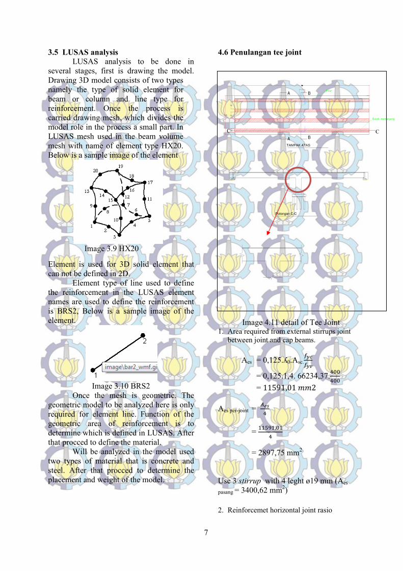
3.5 LUSAS analysis
LUSAS analysis to be done in
several stages, first is drawing the model.
Drawing 3D model consists of two types
namely the type of solid element for
beam or column and line type for
reinforcement. Once the process is
carried drawing mesh, which divides the
model role in the process a small part. In
LUSAS mesh used in the beam volume
mesh with name of element type HX20.
Below is a sample image of the element
Image 3.9 HX20
Element is used for 3D solid element that
can not be defined in 2D.
Element type of line used to define
the reinforcement in the LUSAS element
names are used to define the reinforcement
is BRS2, Below is a sample image of the
element.
Image 3.10 BRS2
Once the mesh is geometric. The
geometric model to be analyzed here is only
required for element line. Function of the
geometric area of reinforcement is to
determine which is defined in LUSAS. After
that procced to define the material.
Will be analyzed in the model used
two types of material that is concrete and
steel. After that procced to determine the
placement and weight of the model.
4.6 Penulangan tee joint
Image 4.11 detail of Tee Joint 1. Area required from external stirrups joint
between joint and cap beams.
Aes = 0,125.ʎ0.Asc.
���
��$
= 0,125.1,4. 66234,37.%��%��
= 11591,01 ''2
Aes per-joint = )*�
%
= ++,-+,�+
%
= 2897,75 mm2
Use 3 stirrup with 4 leght ø19 mm (Aes
pasang = 3400,62 mm2)
2. Reinforcemet horizontal joint rasio
8
ρs = �.� )��ʎ/ 0��
���1"!
Where 234 = 0,3 . dbl. fyc/��′5
= �.� .664�%,�7.+,% .%��
%�� .( �,�.+-.%��/��,)! = 0.19
Aperlu = ρs . b.d
= 0,19.6600.1000= 1.254.000mm2
Use reinforcement ø 19mm with space 200 mm
(Apasang = 1.413.600 mm2).
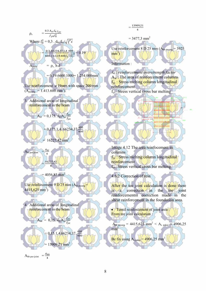
3. Additional areas of longitudinal
reinforcement in the beam
Abl = 0,175. ʎ0.Asc.
���
��$
= 0,175.1,4. 66234,37.%��%��
= 16227,42 mm2
Abl per-joint = )9:
%
= +6447,%4
%
= 4056,85 mm2
Use reinforcement 9 D 25 mm (Abl pasang =
4415,625 mm2)
4. Additional areas of longitudinal
reinforcement in the beam
Abb = 0,15. ʎ0.Asc.
���
��$
= 0,15.1,4.66234,37. %��%��
= 13909,21 mm2
Abb per-joint = )99
%
= +�-�-,4+
%
= 3477,3 mm2
Use reinforcement 8 D 25 mm (Abb pasang = 3925
mm2)
Information :
ʎ0 : reinforcetment overstrength factor
Asc : The area of reinforcement columns
fyc : Stress melting column longitudinal
reinforcement
fyv : Stress vertical cross bar melting
Image 4.12 The area reinfocement in
columns
fyc : Stress melting column longitudinal
reinforcement
fyv : Stress vertical cross bar melting
4.6.2 Correction of rein
After the tee joint calculation is done there
is a correction in the tee joint
reinforcementm correction made in the
shear reinforcement in the foundation area.
• Tensil reinforcement of joint area :
From tee joint calculation :
Abl pasang = 4415,625 mm2 < As pakai = 4906,25
mm2
Be fix using As pakai = 4906,25 mm2
9
5.1 Drawing model in LUSAS
Drawing in LUSAS at the strat by
determining the coordinates of the points on
the axis (x,y,z) which then connect to the
line and become a model to be analyzed.
• First run LUSAS program there will be a
display like this :
Image 5.1 first run LUSAS
chose “create new model” and klik ok, then
this box will appear :
Image 5.2 new model LUSAS
Enter the file name and the title of the model on
the box, and select a unit which in use. Choose a
unit that can not change again. Because the
modeling using the reference from ISO and not
the conposite template in the startup box is filled
with the standard and the box is filled with
structural user interface. Vertical axis here in use
on the X axis, this determiation can be used
which, in accordance with the wishes of the user.
Then click OK then appear like this worksheet :
Gambar 5.3 worksheet LUSAS
5.1.1 Depiction of the beam and beam
reinforcement
To Illustrate beams and columns in the 3D
model is done by selecting Geometry
Shape wizard
Image 5.4 Shape wizard
Then this box will appear :
Image 5.5 Box Shape wizard
Choose Cuboid at column Solid and Volume at
column Type, colunm Origin used to determine
the coordinates of the strating point of the
picture, here begins the coordinates of the point
10
coordinates (0;0;0). Than click Next, Then this
box will appear :
Image 5.6 Shape wizard dimensi
for reinforcement Geometry Point, so to
describe the coordinates of the point and include
reinforcing those points are connected by lines,
then it will be like this :
Image 5.7 Geometry Beam dan reinforcement
Because there are four beams are the same then
the block is copied four blocks the result will be
like this:
Image 5.8 Geometry Beam dan reinforcement
after copies
5.2 Mesh
Mesh is a divison of the model to the elements –
a smaller element.
5.2.1 Mesh at beams and column
For the mesh in the beam and column volume
mesh type.
Image 5.10 mesh Volume
Element code used is the HX20, because the
number of nodes in the model beams and
columns of more than 4 nodes. Once the mesh
the result will look like this :
Image 5.11 Mesh beam and column
5.2.2 Mesh pada tulangan
Mesh in the same way with mesh reinforcement
in beams and columns using only the type of
mesh on the Line, as reinforcement in the model
is defined by line, box for mesh line like this :
11
Image 5.12 Box mesh Line
To define the 3-dimensional
reinforcement within the meaning of the name of
the element which in use is BRS2.
5.3 Attributes
5.3.1 Entering the size of reinforcement
In this section the size of the reinforcement is
determined by clicking Line Geometric
Attributes, and this box will appear:
Image 5.13 Geometric Line
In the column select Element type "bar", then
input-sectional area of reinforcement in the
column "Cross-sectional area (A)"
5.3.2 Defining the type of material
The material used in the model of the
bridge made the same on all parts, the use of
concrete with f'c = 35 MPa and reinforced with
fy = 400 MPa.
To define the material select Material
Attributes Material Library button on the
toolbar
Gambar 5.14 Material Library
Then this box will appear :
Image 5.15 Material Library Concrete
Choose Concrete Material, pada kolom
Grade Select Ungrade, and input units Units
that will be used. Because the use of concrete f'c
= 35Mpa, the value of young modulus calculated
by:
E = 4700.��′5
12
= 4700.�35
= 27805,57 Mpa = 27,8 x 10⁶ KN/m
After clicking OK, select all the parts on
the model and then drag the material that has
been undefined to the worksheet.
As for the reinforcement material used
Mild Steel
5.3.3 Supports
Supports in LUSAS with placement.
LUSAS determination on the placement is more
flexible because we can determine the direction
of rotation and displacement of the placement.
Supports used in the modeling here there are two
kinds:
1. joints
2. clip
Support for the joint type of
displacement on the axis X, Y, Z in the key but
still no rotation. As for the type of clamp,
rotation and displacement in the key of all.
Support kinds of joints used in the node and the
line for beams and columns, the following
picture box Supports joint and clamp type :
Gambar 5.16 Supports Joints
Gambar 5.17 Supports Clip
Choose Attributes Supports, Enter the
direction of displacement and rotation of the
placement After that drag on the elemet a given
placement. The result will be like this:
Gambar 5.18 Model with Supports
5.3.4 Loading
In this section the load acting on the structure
defined. On the toolbar select the Attributes
Loading, then this box will appear:
13
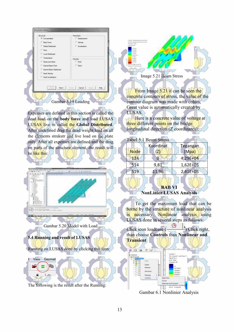
Gambar 5.19 Loading
Expenses are defined in this section is called the
dead load on the body force and load LUSAS
LUSAS live in called the Global Distributed.
After undefined drag the dead weight load on all
the elements strukutr and live load on the plate
only. After all expenses are defined and the drag
on parts of the structure element, the result will