Page 1
1
Analysis and Optimization of the Efficiency of Induction Heating
Applications with Litz-Wire Planar and Solenoidal Coils
Ignacio Lope1,2
, student member, IEEE, Jesús Acero1, member, IEEE, Claudio Carretero
3,
member, IEEE
1Dept. Ingeniería Electrónica y Comunicaciones, Universidad de Zaragoza
María de Luna 1, 50018-Zaragoza, Spain
2BSH Home Appliances Spain
Avenida de la Industria 49, 50016-Zaragoza, Spain
Tel.: (34) 976 762857, Fax: (34) 976 762111, e-mail: [email protected]
3Dept. Física Aplicada, Universidad de Zaragoza
Pedro Cerbuna 12, 50009-Zaragoza, Spain
The first author is the corresponding author.
ABSTRACT- Optimization of the efficiency of an induction heating application is essential
in order to improve both reliability and performance. For this purpose, multi-stranded cables
with litz structure are often used in induction heating applications. This paper presents an
analysis and optimization of the efficiency of induction heating systems focusing on the
optimal copper volume of the winding with respect to different constraints. The analysis is
based on the concept of a one-strand one-turn coil, which captures the dissipative effects of an
induction heating system and reduces the number of variables of the analysis. An expression
for the efficiency of the induction heating system is derived. It is found that, with the
geometry and the other parameters of the system fixed, efficiency depends on the copper
volume of the windings. In order to use this result to optimize the efficiency of an application,
volume restrictions, the packing factor and the window utilization factor are also considered.
The optimum frequency for an induction heating system is also studied in this work. An
experimental verification for both planar and solenoidal cases is also presented.
INDEX TERMS- Electromagnetic analysis, induction heating, loss optimization.
Page 2
2
I. INTRODUCTION
Induction heating technology is applied in many different fields, ranging from medical [1,
2] to industrial uses [3]. Its advantages include efficient and rapid heating as well as electrical
isolation. The basic arrangement of an induction heating system consists of an ac source
feeding a coupled coil-target system. Usually, coils are arranged in several turns following an
axisymmetric geometry adapted to the shape of the induction target. In industrial systems,
solenoid-type induction systems are the most common [4, 5], whereas in medical and
residential applications, planar arrangements are preferred [6, 7]. An illustration of these
arrangements is depicted in Fig. 1.
The designs of induction heating coils are depend on several factors, for example, rated
power, minimum loss, size, temperature, weight or a combination of these. Historically,
copper tubes have been used in the industrial induction heating sphere, because they meet the
specific requirements of frequency (up to several MHz), power (up to hundreds of kW) or
temperature (800 ºC or higher) with a moderate cost. On the other hand, litz wire is the cable
of choice in residential applications, such as induction cookers, mainly due to the optimal
balance between efficiency and cost. Nowadays, the growing concern about efficient power
conversion makes litz wire an interesting option not only for residential applications but also
for industrial applications at the medium range of frequency, power or temperature.
Considering these potential applications, it is important to have in mind temperature
(a) (b)
Fig. 1. Typical induction heating arrangements. (a) Planar. (b) Solenoidal.
Page 3
3
limitations of litz wire, which depends on the working temperature of the insulation materials.
Therefore, litz wire coils could not be appropriate for some induction heating applications as
melting, forging, or brazing because radiant or convection heating of the coil may exceed its
limit temperature. However, there are other industrial applications, as the sealing of cans by
means of aluminum caps, where litz wire could be an interesting option. Moreover, litz wire
could be also used in combination with appropriate low-emissive bobbins (such as ceramic
materials) with moderate increase the temperature due the radiation of the workpiece.
Litz wire has been object of study in many papers, mainly with the aim of loss modeling
[8-13] and optimal design [14-18] of inductors and transformers for Switch Mode Power
Supplies (SMPS). Comparatively, the number of studies devoted to litz-wire windings for
induction heating applications is small, which in part is due to the fact that the sphere of use
and market for SMPS are quite different from those of induction heating. The existing works
in the field of induction heating are mainly focused on loss modeling [19, 20] and efficiency
analysis [21]. The studies mentioned above for SMPS could to a greater or a lesser extent be
applied to induction heating and they are undoubtedly a valuable starting point. However,
coils for induction heating systems have several differences compared to the magnetic
components of SMPS and, therefore, there is room for further contributions, especially in the
field of the efficiency-oriented design.
The design of inductors and transformers is often focused on the minimization of winding
losses, which can be accomplished by an appropriate selection of the number and radius of the
strands, while considering other restrictions such as the total volume or cost. However, the
design of induction heating coils should rather be focused on the efficiency of energy
transference, which depends on both the dissipation in the workpiece and the losses of the
windings. In an induction system these dissipations are not decoupled: rather, both depend on
the global magnetic field of the specific application and the frequency, being of special
Page 4
4
importance the frequency dependency which should be accounted for in order to optimize the
induction heating system.
The winding volume of inductors and transformers for SMPS is usually closely related to
the size of the bobbin and the core. The design tools developed by manufacturers or
researchers [16] often includes a list of the standard bobbins in order to check if the volume
occupied by the windings of the designs fits in a specific bobbin. In the induction heating
field the winding volume mainly depends on the available space in each specific application,
and sometimes this is a major restriction which makes the design more difficult. For example,
in domestic induction heating appliances (both conventional [22] or total active surfaces
[23]), the assembly of coils and power electronics in the housing imposes severe volume
restrictions which are reflected in the design of the inductors. Volume restrictions become
more evident in PCB implementations of planar windings with litz-wire structure [24, 25] and
microfabricated inductors [26]. In other applications, the dissipated heat must be concentrated
in a small area and therefore the coil should be adapted to the heating zone.
Considering the aforementioned differences, in this paper we present a study on induction
heating systems with litz wire focusing on the optimization of the efficiency with respect to
the copper volume. Different restrictions such as the operating frequency, the window area
utilization or the radius of the strands are also considered. For this purpose, a semi-analytical
method combining finite element (FEA) field simulations and formulas for calculating the
loss is followed. This paper is organized as follows. In Section II an electromagnetic analysis
of the efficiency of an induction heating system is presented. Section III describes the design
issues. Section IV presents an experimental verification of the proposed model, and Section V
summarizes the findings of this study.
II. ELECTROMAGNETIC ANALYSIS OF THE INDUCTION HEATING
EFFICIENCY
Page 5
5
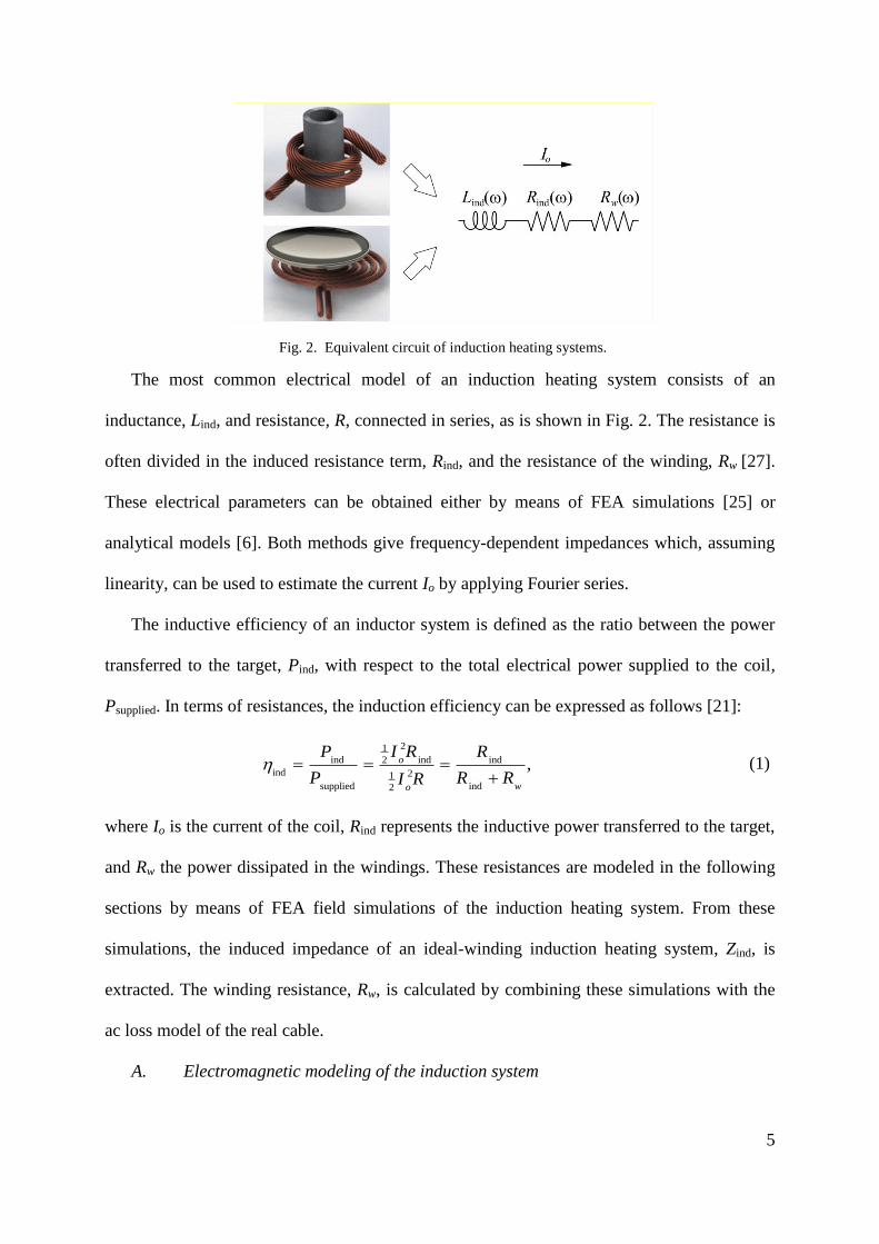
The most common electrical model of an induction heating system consists of an
inductance, Lind, and resistance, R, connected in series, as is shown in Fig. 2. The resistance is
often divided in the induced resistance term, Rind, and the resistance of the winding, Rw [27].
These electrical parameters can be obtained either by means of FEA simulations [25] or
analytical models [6]. Both methods give frequency-dependent impedances which, assuming
linearity, can be used to estimate the current Io by applying Fourier series.
The inductive efficiency of an inductor system is defined as the ratio between the power
transferred to the target, Pind, with respect to the total electrical power supplied to the coil,
Psupplied. In terms of resistances, the induction efficiency can be expressed as follows [21]:
indind ind
ind
supplied ind
21
2
21
2
,
o
wo
I RP R
P R RI R (1)
where Io is the current of the coil, Rind represents the inductive power transferred to the target,
and Rw the power dissipated in the windings. These resistances are modeled in the following
sections by means of FEA field simulations of the induction heating system. From these
simulations, the induced impedance of an ideal-winding induction heating system, Zind, is
extracted. The winding resistance, Rw, is calculated by combining these simulations with the
ac loss model of the real cable.
A. Electromagnetic modeling of the induction system
Fig. 2. Equivalent circuit of induction heating systems.
Page 6
6
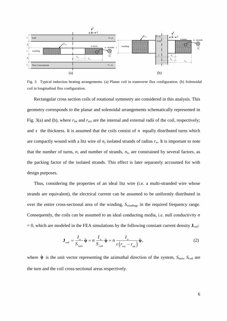
Rectangular cross section coils of rotational symmetry are considered in this analysis. This
geometry corresponds to the planar and solenoidal arrangements schematically represented in
Fig. 3(a) and (b), where rint and rext are the internal and external radii of the coil, respectively;
and t the thickness. It is assumed that the coils consist of n equally distributed turns which
are compactly wound with a litz wire of ns isolated strands of radius rw. It is important to note
that the number of turns, n, and number of strands, ns, are constrained by several factors, as
the packing factor of the isolated strands. This effect is later separately accounted for with
design purposes.
Thus, considering the properties of an ideal litz wire (i.e. a multi-stranded wire whose
strands are equivalent), the electrical current can be assumed to be uniformly distributed in
over the entire cross-sectional area of the winding, Swinding, in the required frequency range.
Consequently, the coils can be assumed to an ideal conducting media, i.e. null conductivity σ
= 0, which are modeled in the FEA simulations by the following constant current density Jcoil:
coil
turn coil ext int
φ φ φˆ ˆ ˆo o oI I I
n nS S t r r
J , (2)
where φ is the unit vector representing the azimuthal direction of the system, Sturn, Scoil are
the turn and the coil cross-sectional areas respectively.
(a) (b)
Fig. 3. Typical induction heating arrangements. (a) Planar coil in transverse flux configuration. (b) Solenoidal
coil in longitudinal flux configuration.
z
-turnsnld
fd
ft
intrextr
t
r
coilJ
winding
lt
Flux Concentrator
load
,f f
,l l
φ
-strandssn
2 wr
z
-turnsn
intrextr
t
rcoilJ
winding
φ
-strandssn
2 wr
,l l
load
lt ld
Page 7
7
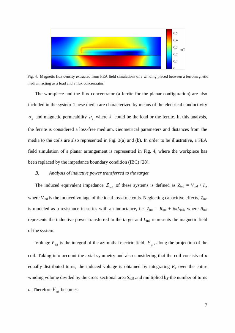
The workpiece and the flux concentrator (a ferrite for the planar configuration) are also
included in the system. These media are characterized by means of the electrical conductivity
k
and magnetic permeability k
where k could be the load or the ferrite. In this analysis,
the ferrite is considered a loss-free medium. Geometrical parameters and distances from the
media to the coils are also represented in Fig. 3(a) and (b). In order to be illustrative, a FEA
field simulation of a planar arrangement is represented in Fig. 4, where the workpiece has
been replaced by the impedance boundary condition (IBC) [28].
B. Analysis of inductive power transferred to the target
The induced equivalent impedance ind
Z of these systems is defined as Zind = Vind / Io,
where Vind is the induced voltage of the ideal loss-free coils. Neglecting capacitive effects, Zind
is modeled as a resistance in series with an inductance, i.e. Zind = Rind + jωLind, where Rind
represents the inductive power transferred to the target and Lind represents the magnetic field
of the system.
Voltage ind
V is the integral of the azimuthal electric field,
E , along the projection of the
coil. Taking into account the axial symmetry and also considering that the coil consists of n
equally-distributed turns, the induced voltage is obtained by integrating Eφ over the entire
winding volume divided by the cross-sectional area Scoil and multiplied by the number of turns
n. Therefore ind
V becomes:
Fig. 4. Magnetic flux density extracted from FEA field simulations of a winding placed between a ferromagnetic
medium acting as a load and a flux concentrator.
Page 8
8
ext
intind
winding coil02 .
E dl
r t
r
nV rE dzdr
S (3)
where Eφ is obtained from the FEA simulations and r is the radial coordinate .
Regarding the equivalent impedance, the number of turns of the coil is of especial
relevance. In order to parameterize the number of turns it is convenient to consider coils with
only one turn, i.e. 1n , and the same geometries of those presented in Fig. 3. These coils are
here called as one-turn coils. Let ,1
E be the electric field generated by a one-turn coil.
Therefore, the corresponding one-turn voltage ind,1
V is:
ext
intind,1
coil
,10
12 .
r t
rV rE drdz
S (4)
It is worth to note that the length of the one-turn coil corresponds to the average length of
the turns of the coil, also calledMLT , which is defined as:
ext
intext int
coil0
12 .
r t
rMLT rdrdz r r
S (5)
Assuming linearity of the media, the field
E of (3) can be calculated as
,1E nE
Therefore, (3) can be rewritten as follows:
ext
int
ind,1
ind ind,1
coil
2
,10
12 .
r t
r
V
V n n rE drdz n VS
(6)
Therefore, the impedance of the loss-free coil is:
ind
ind ind ind,1 ind,1
,12 2 2 2
,1
0
, V
Z n n Z n R j n LI
(7)
where ind,1
Z , ind,1
R and ind,1
L are the impedance, resistance and inductance of the one-turn
coil, respectively.
Page 9
9
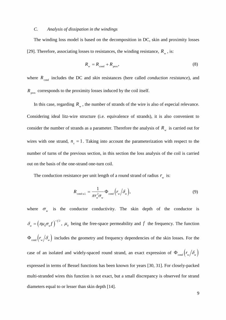
C. Analysis of dissipation in the windings
The winding loss model is based on the decomposition in DC, skin and proximity losses
[29]. Therefore, associating losses to resistances, the winding resistance, w
R , is:
cond prox
, w
R R R (8)
where cond
R includes the DC and skin resistances (here called conduction resistance), and
proxR corresponds to the proximity losses induced by the coil itself.
In this case, regarding w
R , the number of strands of the wire is also of especial relevance.
Considering ideal litz-wire structure (i.e. equivalence of strands), it is also convenient to
consider the number of strands as a parameter. Therefore the analysis of w
R is carried out for
wires with one strand, 1s
n . Taking into account the parameterization with respect to the
number of turns of the previous section, in this section the loss analysis of the coil is carried
out on the basis of the one-strand one-turn coil.
The conduction resistance per unit length of a round strand of radius w
r is:
cond u.l. cond
2
1,
w w
w w
R rr
(9)
where w
is the conductor conductivity. The skin depth of the conductor is
1 2
0w wf ,
0 being the free-space permeability and f the frequency. The function
cond
w wr includes the geometry and frequency dependencies of the skin losses. For the
case of an isolated and widely-spaced round strand, an exact expression of cond
w wr
expressed in terms of Bessel functions has been known for years [30, 31]. For closely-packed
multi-stranded wires this function is not exact, but a small discrepancy is observed for strand
diameters equal to or lesser than skin depth [14].
Page 10
10
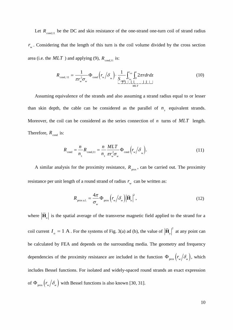
Let cond,11
R be the DC and skin resistance of the one-strand one-turn coil of strand radius
wr . Considering that the length of this turn is the coil volume divided by the cross section
area (i.e. the MLT ) and applying (9), cond,11
R is:
ext
intcond, 11 cond
coil
2 0
1 12
r t
w rww w
MLT
R r rdrdzSr
(10)
Assuming equivalence of the strands and also assuming a strand radius equal to or lesser
than skin depth, the cable can be considered as the parallel of s
n equivalent strands.
Moreover, the coil can be considered as the series connection of n turns of MLT length.
Therefore, cond
R is:
cond cond,11 cond
2.
w ws s w w
n n MLTR R r
n n r (11)
A similar analysis for the proximity resistance, prox
R , can be carried out. The proximity
resistance per unit length of a round strand of radius w
r can be written as:
prox u.l. prox
24,
w w o
w
R r H (12)
where o
H is the spatial average of the transverse magnetic field applied to the strand for a
coil current A 1o
I . For the systems of Fig. 3(a) ad (b), the value of 2
oH at any point can
be calculated by FEA and depends on the surrounding media. The geometry and frequency
dependencies of the proximity resistance are included in the function prox
w wr , which
includes Bessel functions. For isolated and widely-spaced round strands an exact expression
of prox
w wr with Bessel functions is also known [30, 31].
Page 11
11
Let prox,11
R be the proximity resistance of the one-strand one-turn coil of strand radius w
r .
This resistance can be calculated by applying (12), which requires 2
,1oH , i.e., the spatial
average of the field generated by the one-turn coil at the positions of the coil. This value is
obtained by integrating 2
,12
or H on the coil volume and dividing by the cross-sectional
area:
coil
prox prox
coil
2
,11 ,1
4 12 .
H
w w o
Sw
R r r drdzS
(13)
Assuming linearity of the media, o
H can be expressed as the field generated by the the
one-strand one-turn coil, ,1o
H , multiplied by the number of turns, i.e. ,1o o
nH H .
Moreover, as in the section above, the cable is considered as the parallel of s
n strands and the
coil is the series connection of n equally distributed turns. Therefore:
coil
prox prox prox,11
23 3
,1
42 ,
s w o swSw
R n n r r n n RH (14)
where
coil
2
,12
oS
r H is the mean value of 2
,12
or H in the cross-sectional area of the coil.
It is worth noting several aspects of the last equation. Firstly, the magnetic field ,1o
H is
frequency-dependent because conductive media are present in the system. Secondly,
TABLE I: IMPEDANCE COMPONENTS
Component Symbol Expression One-turn equivalent coil of one-strand
Induction impedance ind
Z ind ind,1
2Z n Z ext
intind,1
coil
,10
12
r t
rZ rE dS
S
Conduction resistance cond
R cond cond,11
s
nR R
n turn
cond,11 cond
2
w
ww w
l rR
r
Proximity resistance prox
R prox prox,11
3
sR n n R
coil
prox,11 prox
2
,1
42w
oSw w
rR r H
Page 12
12
according to the ideal model coil adopted, ,1o
H is not affected by the self-induced currents in
the coil conductors. This assumption is potentially valid if cables with enough stranding level
are used. Third, considering that prox
w wr of (14) is only valid for isolated and widely-
spaced round strands, this equation cannot be considered as exact. However, the
approximation (14) is valid if the strand radius is equal to or lesser than skin depth. Some
authors have further evaluated this approximation [12].
The impedance contributions in induction heating systems and their dependencies with
respect to n and s
n are summarized in Table I.
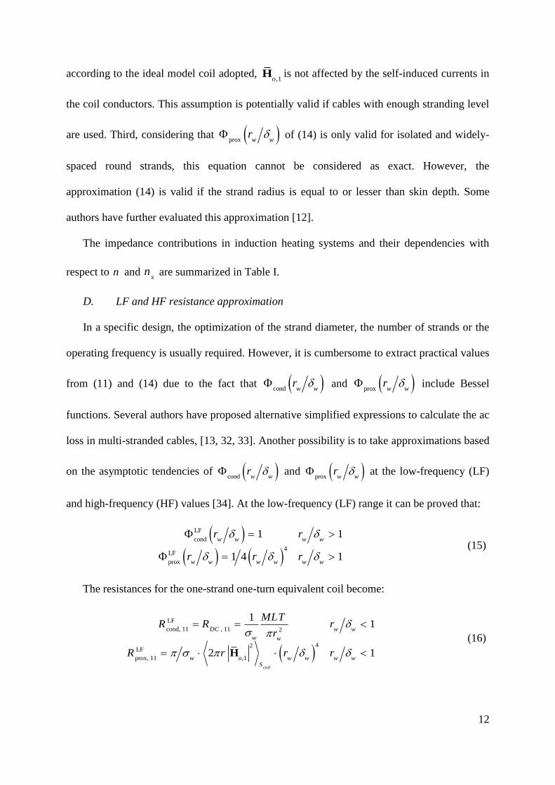
D. LF and HF resistance approximation
In a specific design, the optimization of the strand diameter, the number of strands or the
operating frequency is usually required. However, it is cumbersome to extract practical values
from (11) and (14) due to the fact that cond
w wr and prox
w w
r include Bessel
functions. Several authors have proposed alternative simplified expressions to calculate the ac
loss in multi-stranded cables, [13, 32, 33]. Another possibility is to take approximations based
on the asymptotic tendencies of cond
w wr and prox
w w
r at the low-frequency (LF)
and high-frequency (HF) values [34]. At the low-frequency (LF) range it can be proved that:
LF
cond
LF
prox
4
1 1
1 4 1
w w w w
w w w w w w
r r
r r r (15)
The resistances for the one-strand one-turn equivalent coil become:
coil
LF
cond, 11 , 11
LF
prox, 11
2
42
,1
11
2 1
H
DC w w
w w
w o w w w wS
MLTR R r
r
R r r r
(16)
Page 13
13
Taking into account the assumptions of uniform current coil distribution and strand radius
equal to or lesser than skin depth, the LF approximation is used in order to obtain practical
and simple equations for the design of induction heating systems.
Concluding this section, the main assumptions adopted in the presented modeling are
summarized as follows:
Ideal winding modeled as a constant current density.
Linear materials and loss-free flux concentrators, which allows to use the Fourier
series to obtain the current for any periodic voltage waveform.
Ideal litz-wire structure.
Widely-spaced round strands.
Low frequency approximation of the frequency-dependent strand losses.
III. EFFICIENCY-ORIENTED DESIGN
A study of the induction efficiency has been carried out, focusing on the optimization of
the induction efficiency with respect to some practical parameters such as the operation
frequency, the winding parameters and the coil volume.
A. Induction efficiency and coil volume
Considering the previous modeling and applying (1), (7), (8), (11) and (14), the induction
efficiency can be expressed as:
ind,1
ind
ind,1 cond,11 prox,11
.1
s s
R
R nn R nn R (17)
According to this expression, induction efficiency depends on the resistances
corresponding to the one-strand one-turn coil, ind,1
R , cond,11
R , prox,11
R (which includes the
frequency-dependency) and the factor s
nn , i.e. the number of turns multiplied by the number
Page 14
14
of strands. It can also be deduced that the induction efficiency depends on the copper volume
defined as 2
Cu s wV nn r MLT .
Therefore, if the system geometry, the wire radius w
r and the operating frequency are
fixed, different coils with the same result of the number of turns multiplied by the number of
strands, s
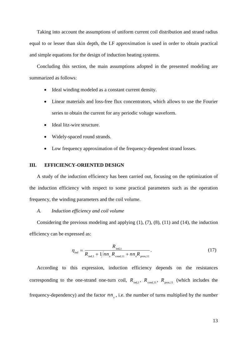
nn , (i.e. coils with the same copper volume) have the same efficiency. Fig. 5 shows
the induction efficiency for different s
nn factors (continuous line) with respect to the
frequency for a given wire radius (rw = 0.1 mm).
In the following sections, equation (17) is used to optimize the induction efficiency for
design purposes.
B. Condition of maximum efficiency
When the winding area without geometrical restrictions, the frequency and the wire radius
wr are fixed, the solution of ind
0s
nn gives the s
nn which maximizes the induction
efficiency. It is worth noting that, in this case, the maximum winding area is not restricted by
Fig. 5. Induction efficiency with respect to the frequency for different factors s
nn (continuous line), for the
optimum value of ,maxs s
nn nn (dashed cyan line) and with respect to the optimum frequency opt
f f for given
snn and wire radius rw (dashed magenta line). The system corresponds to a solenoidal coil with mm 0.1
wr
with a ferromagnetic load in longitudinal flux configuration.
Page 15
15
the winding area of a bobbin (which is associated to a magnetic core) as occurs in SMPS.
Rather, it depends on the specific induction heating application. According to (17), the
following condition is obtained:
cond,11 prox,11,max
.s
nn R R (18)
The same condition can be obtained if cond prox
R R or, in other words, if the optimum
efficiency occurs when the conduction (DC+skin) equals the proximity resistances. This result
has also been found by other authors, as can be seen in several works concerning litz-wire
transformer winding [14]. The maximum induction efficiency ind max
,
for a given system is
represented by the dashed cyan line in Fig. 5, which corresponds to the envelope of the set of
curves obtained for different values of s
nn . This envelope was numerically obtained and
subsequently represented. Nevertheless, ind max
,
can be analytically obtained by applying the
result (18) in (17) giving:
ind,1
ind,max
ind,1 cond,11 prox,11
.2
R
R R R (19)
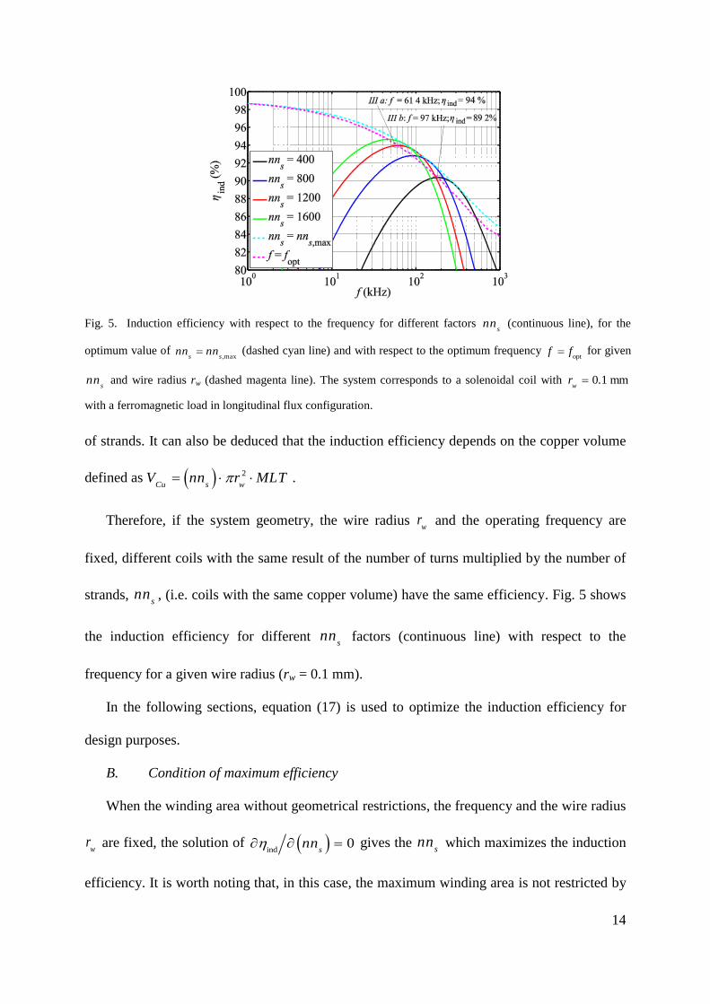
Fig. 6 shows the factor ,maxs
nn as a function of frequency for different strand radii. As is
shown, at a low frequency regime, the higher the frequency, the lower the ,maxs
nn . In other
words, for the same strand radius, an increase in the frequency allows either the number of
turns or the number of strands to be reduced achieving the maximum efficiency. At a high
frequency regime, ,maxs
nn is much more constant with respect to the frequency.
Equation (18) gives the theoretical ,maxs
nn value that maximizes the induction efficiency.
However, for design purposes, in order to make the selection of w
r easier, it is more useful to
have an expression of ,maxs
nn in terms of w
r than in terms of cond,11 prox,11
,R R because the latter
Page 16
16
include Bessel functions among other dependencies. Therefore, applying the LF
approximation of cond,11 prox,11
,R R (16), ,maxs
nn is rewritten as follows:
coil
LF
,max 32
,1
1 1 11.
2
Hs w w
w o wo
S
MLTnn r
f rr
(20)
Moreover, applying the LF approximation, the maximum inductive efficiency, ind max
,
is
given by:
coil
LF ind,1
ind,max
ind,1
2
0
,1
1, 1.
2w w
w
oS
Rr
rR MLT r H
(21)
C. Frequency design for maximum efficiency
Equation (18) provides the factor ,maxs
nn which maximizes ind
. According to the results
presented in Fig. 5, it may seem that the maximum efficiency of a design can be achieved by
simply selecting the appropriate ,maxs
nn at a given frequency using the envelope of the ind max
,
,
Fig. 6. Factor ,maxs
nn which maximizes the efficiency as a function of the frequency for different strand radii
(continuous line). Factor s
nn which maximizes the efficiency at opt
f for different strand radii (dashed line).
Available ava,s
nn for the solenoidal configuration of Table III (dashed line of constant value)
Page 17
17
which is represented by the cyan curve. However, in some cases the factor s
nn could be fixed
for different reasons, for example for a fixed number of turns or a fixed number of strands,
and the optimization should be performed for a specific s
nn . In these cases, it may also be
interesting to obtain the frequency opt
f maximizing the inductive efficiency.
Therefore, for a specific s
nn factor, the theoretical frequency opt
f at which the maximum
efficiency is achieved can be obtained by ind
/ 0f , where ind
is given by (17). Taking
into account that several terms of this equation, such as ind 1 cond prox
,, ,
w w w wR r r
and the magnetic field, are frequency dependent and therefore are not straightforwardly
derivable with respect to the frequency, the solution of the above mentioned condition has
been obtained using post-processing numerical calculations. Fig. 5 shows the ind
considering
the frequency axis as the opt
f for a set of different s
nn values. This line corresponds to the
peak values of the efficiency curves for different s
nn values and it is represented by a dashed
magenta line. It is worth noting that this line is very close but not coincident with the ind max
,
obtained in the previous section. The difference lies in the fact that ind max
,
corresponds to the
envelope whereas the ind
at the optimal frequencyopt
f corresponds instead to the peak of the
efficiency curves.
Curves of s
nn which maximize ind
at opt
f for different strand radii are also shown in Fig.
6 with slopping dashed lines. As in the previous case, this line is close but not coincident with
,maxsnn for the reasons above commented.
Page 18
18
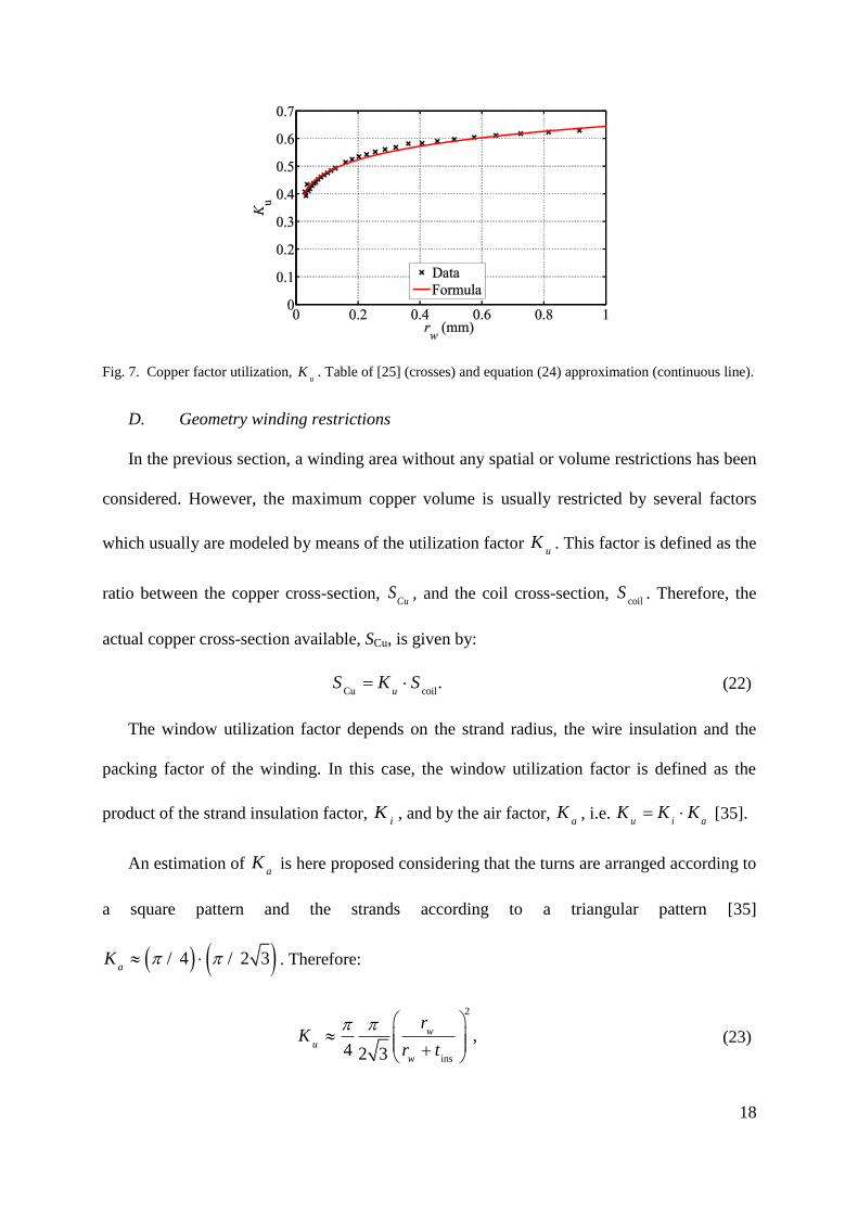
D. Geometry winding restrictions
In the previous section, a winding area without any spatial or volume restrictions has been
considered. However, the maximum copper volume is usually restricted by several factors
which usually are modeled by means of the utilization factor u
K . This factor is defined as the
ratio between the copper cross-section, Cu
S , and the coil cross-section, coil
S . Therefore, the
actual copper cross-section available, SCu, is given by:
Cu coil
. u
S K S (22)
The window utilization factor depends on the strand radius, the wire insulation and the
packing factor of the winding. In this case, the window utilization factor is defined as the
product of the strand insulation factor, i
K , and by the air factor, a
K , i.e. u i a
K K K [35].
An estimation of a
K is here proposed considering that the turns are arranged according to
a square pattern and the strands according to a triangular pattern [35]
4 2 3 / /a
K . Therefore:
ins
2
,4 2 3
w
u
w
rK
r t (23)
Fig. 7. Copper factor utilization, u
K . Table of [25] (crosses) and equation (24) approximation (continuous line).
Page 19
19
where ins
t is the insulation thickness. The window utilization factor can be approximated by a
power law as follows [14]:
.b
u w aK r r (24)
Parameters 2979 m 0.0a
r and 1295 0.b have been obtained by means of a curve-fit
tool from data provided by the manufacturers for double insulation strands [36]. The
manufacturer’s curve and the fitted data are compared in Fig. 7. The approximation adopted
here only considers simple arrangements which consist of a group of strands bunched and
twisted into a bundle. Therefore, it doesn’t take into account more complex constructions
consisting of several groups, like those described above, which are twisted into higher level
bundles. Apart from this consideration, other packing factors can be considered and included
by adapting the parameters a
r and b .
Considering the window utilization factor and also considering (22) the available s
nn is:
ava coil
2
,.
s u wnn K S r (25)
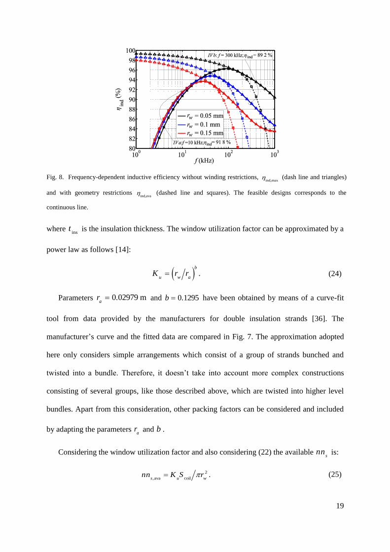
Fig. 8. Frequency-dependent inductive efficiency without winding restrictions, ind,max
(dash line and triangles)
and with geometry restrictions ind,ava
(dashed line and squares). The feasible designs corresponds to the
continuous line.
Page 20
20
According to Fig. 7, design with small strands have smaller utilization factor. Fig. 6 shows
(dashed line of constant value) the ava,s
nn for the solenoidal configuration of the Table II and
different strand radii. This value is proportional to the available copper cross section for this
specific geometry.
The induction efficiency corresponding to the available copper volume, ind ava
,
is obtained
by inserting ava,s
nn in (17). Fig. 8 shows both the maximum efficiency without restrictions
ind,max and with restrictions
ind ava
, for different strand radii. The point where both efficiencies
meet corresponds to an optimum design which takes exactly the available volume. At lower
frequencies the theoretical s
nn would require more space than is available and therefore
designs with maximum efficiency are not feasible and efficiency decreases. However, at
higher frequencies the theoretical s
nn would require less space than is available and therefore
the efficiency is coincident with ind,max
. In Fig. 8 the curve of feasible designs, composed of
sections of the ind,max
and ind ava
,
curves, is represented by continuous line.
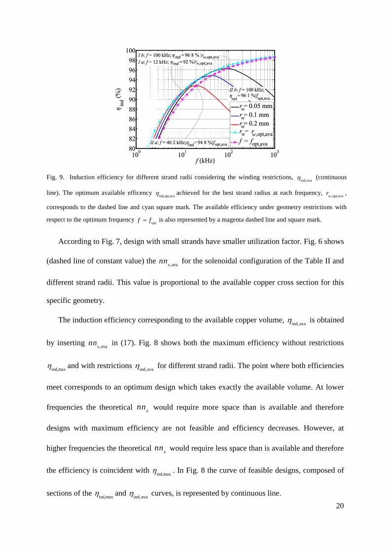
Fig. 9. Induction efficiency for different strand radii considering the winding restrictions, ind ava
,
(continuous
line). The optimum available efficency ind,opt,ava
achieved for the best strand radius at each frequency, opt,ava,w
r ,
corresponds to the dashed line and cyan square mark. The available efficiency under geometry restrictions with
respect to the optimum frequency opt
f f is also represented by a magenta dashed line and square mark.
Page 21
21
As has been mentioned, ind ava
,
is obtained by considering ava,s
nn in (17). Applying the LF
asymptotic approximation, the following available efficiency is obtained:
coil
LF ind,1
ind,ava
ind,1 coil
coil
2
2
,14
1 12
u w oSu w w w
R
MLTR K S r r
K SH
(26)
From the design point of view, it is of interest to calculate the strand radius which
provides the optimum efficiency at a fixed frequency considering the geometry restrictions
opt,ava,wr and also considering the system geometry. This radius can be obtained by applying the
condition LF
ind,ava0
wr in (26), resulting in the following expression:
opt,ava
coil
1
1
2
, 2
,1
.2
2
H
bb
a w
w
o
rb MLTr
b Sr
(27)
The optimum efficiency achieved with these strands, ind,opt,ava
, can be calculated by inserting
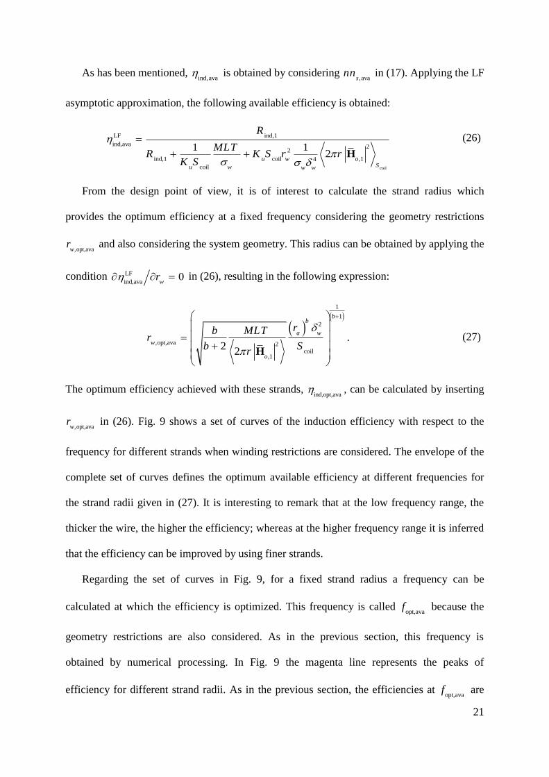
opt,ava,wr in (26). Fig. 9 shows a set of curves of the induction efficiency with respect to the
frequency for different strands when winding restrictions are considered. The envelope of the
complete set of curves defines the optimum available efficiency at different frequencies for
the strand radii given in (27). It is interesting to remark that at the low frequency range, the
thicker the wire, the higher the efficiency; whereas at the higher frequency range it is inferred
that the efficiency can be improved by using finer strands.
Regarding the set of curves in Fig. 9, for a fixed strand radius a frequency can be
calculated at which the efficiency is optimized. This frequency is called opt,ava
f because the
geometry restrictions are also considered. As in the previous section, this frequency is
obtained by numerical processing. In Fig. 9 the magenta line represents the peaks of
efficiency for different strand radii. As in the previous section, the efficiencies at opt,ava
f are
Page 22
22
lower than the envelope curve called ind,opt,ava
. This fact can be explained by means of an
example. The peak efficiency of the strand radius 0.05w
r mm at opt,ava
100f kHz is
slightly higher than 96%. However, the cyan curve indicates that a ind,opt,ava
96.8% could be
achieved at 100f kHz by using a strand with a radius smaller than 0.05w
r mm. Some
results which could help when selecting the strand radius for optimal efficiency at a fixed
frequency are given in the next section.
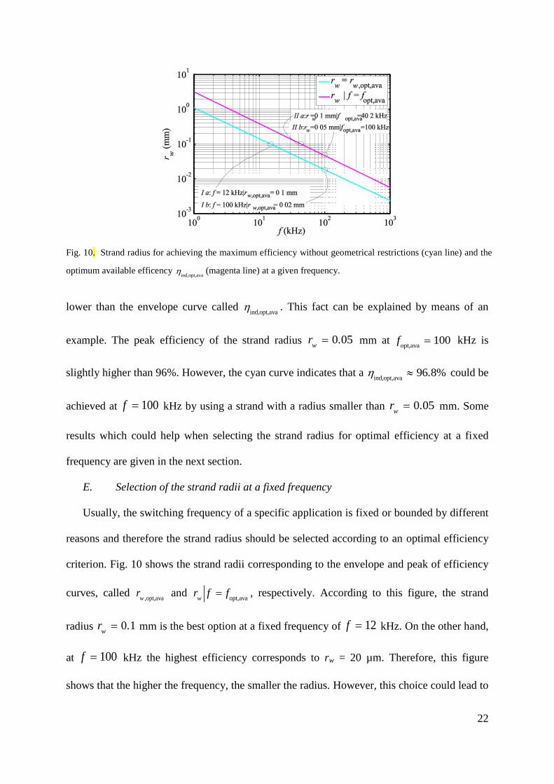
E. Selection of the strand radii at a fixed frequency
Usually, the switching frequency of a specific application is fixed or bounded by different
reasons and therefore the strand radius should be selected according to an optimal efficiency
criterion. Fig. 10 shows the strand radii corresponding to the envelope and peak of efficiency
curves, called ,opt,avaw
r and opt,ava
w
r f f , respectively. According to this figure, the strand
radius 0.1w
r mm is the best option at a fixed frequency of 12f kHz. On the other hand,
at 100f kHz the highest efficiency corresponds to rw = 20 µm. Therefore, this figure
shows that the higher the frequency, the smaller the radius. However, this choice could lead to
Fig. 10. Strand radius for achieving the maximum efficiency without geometrical restrictions (cyan line) and the
optimum available efficency ind,opt,ava
(magenta line) at a given frequency.
Page 23
23
small radius and expensive designs. Considering that the cost of litz wire greatly depends on
the strand diameter, several authors have proposed design methods including not only the
efficiency but also the cost [15].
F. Practical design guidance
Before ending this section, a guidance of possible methodology intended to optimize the
efficiency of an induction heating system is presented. This guidance is based on the
optimization of different scenarios with different specifications. Two different cases are
considered in each scenario.
TABLE II: PRACTICAL DESIGN EXAMPLES INCLUDING GEOMETRY RESTRICTIONS
Scenario I: Maximum efficiency design given the frequency
Parameter Case-I.a Case-I.b Calculation Equation Figure
f 12.0 kHz 100.0 kHz Specification -- --
rw 100 µm 20 µm rw,opt,ava (27) Fig. 10
nns 1764 35800 nns,ava |rw = rw,opt,ava (25) Fig. 6
ηind 92.0 % 96.8 % ηLF
ind,ava |rw = rw,opt,ava, f (26) Fig. 9
Scenario II: Frequency design for maximum efficiency given the wire radius
Parameter Case-II.a Case-II.b Calculation Equation Figure
f 40.2 kHz 100.0 kHz f = fopt,ava ∂ηind,ava/∂f = 0 Fig. 9
rw 100 µm 50 µm Specification -- --
nns 1764 6450 nns| f = fopt,ava, rw (25) Fig. 6
ηind 94.8 % 96.1 % ηLF
ind,ava| f = fopt,ava, rw (26) Fig. 9
Scenario III: Frequency design for a fixed prototype
Parameter Case-III.a Case-III.b Calculation Equation Figure
f 61.4 kHz 175 kHz f = fopt ∂ηind /∂f = 0 Fig. 5
rw 100 µm 100 µm Specification -- --
nns 1200 400 Specification -- --
ηind 94.0 % 90.2 % ηind | f = fopt, nns, rw (21) Fig. 5
Scenario IV: Optimal copper volume design given wire radius and frequency
Parameter Case-IV.a Case-IV.b Calculation Equation Figure
f 10 kHz 300 kHz Specification -- --
rw 100 µm 100 µm Specification -- --
nns 1764 388 nns,max ≤ nns,ava (18), (25) Fig. 6
ηind 94 % 89.2 % ηind,max, ηind,ava (19) Fig. 8
Table II summarizes these scenarios and also includes the specified parameters
(highlighted by gray), the equations used in each case, the resulting parameters of the
Page 24
24
calculations, and the figures used in the optimization. For this reason, the ordinal number of
scenarios and cases also corresponds to the labels which appear in curves of Fig. 5, Fig. 6,
Fig. 8, Fig. 9, Fig. 10. The optimization carried out in some scenarios is explained as follows.
Scenario I corresponds to an optimization case in which the frequency is specified and the
radius of the strand, the number of turns and the number of strands for maximum efficiency
have to be determined. In this case, the strand radius is calculated by means of (27). Once
rw,opt,ava is calculated, the available product of the number of turns by the number of strands is
calculated by means of (25). The achieved efficiency at this design is obtained by using (26).
In the Scenario II the radius of the strand is specified and the optimization consists of
calculating the frequency, the number of strands and turns which maximizes the efficiency.
Scenario III corresponds to a case where the prototype geometry is specified and the
optimization consists of determining the frequency which maximizes the efficiency. Finally,
in scenario IV the copper volume which optimizes the efficiency for a given strand radius and
frequency is determined. This optimization is often required for magnetic design of SMPS.
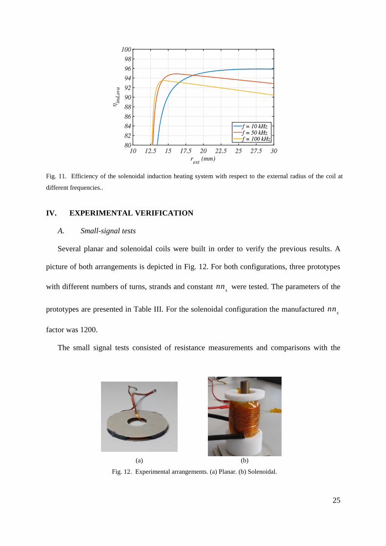
Before ending this Section, it is worth to comment some aspects of the design of
solenoidal arrangements (Fig. 3(b)) because its design is more similar to the magnetic design
for SMPS than planar arrangements (Fig. 3(a)). In magnetic design for SMPS, it is usual to
consider if a specific design fits in a smaller bobbin in order to reduce the size of the
application. Redesigns usually lead to changes of some parameters, as the frequency or the
strand radius. Similarly, the effect of the external radius of the solenoidal arrangement of
Table III (whose internal radius is 12. 5 mm) is analyzed by means of the presented method.
The results are presented in Fig. 11. As it is shown, designs with smaller external radii can be
obtained by increasing the operating frequency. In general it is also observed that at a fixed
frequency, the increase of the external radius lead to a reduction of the efficiency.
Page 25
25
IV. EXPERIMENTAL VERIFICATION
A. Small-signal tests
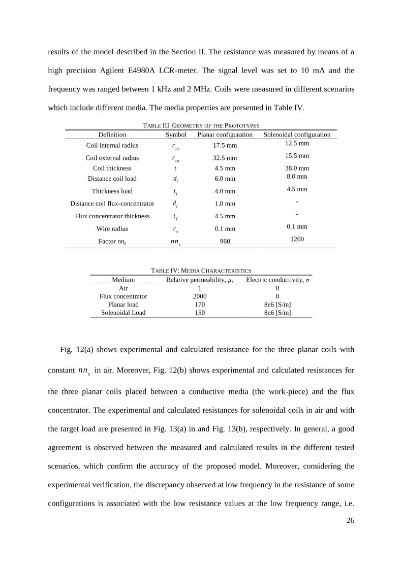
Several planar and solenoidal coils were built in order to verify the previous results. A
picture of both arrangements is depicted in Fig. 12. For both configurations, three prototypes
with different numbers of turns, strands and constant s
nn were tested. The parameters of the
prototypes are presented in Table III. For the solenoidal configuration the manufactured s
nn
factor was 1200.
The small signal tests consisted of resistance measurements and comparisons with the
(a) (b)
Fig. 12. Experimental arrangements. (a) Planar. (b) Solenoidal.
Fig. 11. Efficiency of the solenoidal induction heating system with respect to the external radius of the coil at
different frequencies..
Page 26
26
results of the model described in the Section II. The resistance was measured by means of a
high precision Agilent E4980A LCR-meter. The signal level was set to 10 mA and the
frequency was ranged between 1 kHz and 2 MHz. Coils were measured in different scenarios
which include different media. The media properties are presented in Table IV.
TABLE III GEOMETRY OF THE PROTOTYPES
Definition Symbol Planar configuration Solenoidal configuration
Coil internal radius int
r 17.5 mm 12.5 mm
Coil external radius ext
r 32.5 mm 15.5 mm
Coil thickness t 4.5 mm 38.0 mm
Distance coil load l
d 6.0 mm 8.0 mm
Thickness load l
t 4.0 mm 4.5 mm
Distance coil flux-concentrator fd 1.0 mm -
Flux concentrator thickness ft 4.5 mm -
Wire radius w
r 0.1 mm 0.1 mm
Factor nns snn 960 1200
TABLE IV: MEDIA CHARACTERISTICS
Medium Relative permeability, µr Electric conductivity, σ
Air 1 0
Flux concentrator 2000 0
Planar load 170 8e6 [S/m]
Solenoidal Load 150 8e6 [S/m]
Fig. 12(a) shows experimental and calculated resistance for the three planar coils with
constant s
nn in air. Moreover, Fig. 12(b) shows experimental and calculated resistances for
the three planar coils placed between a conductive media (the work-piece) and the flux
concentrator. The experimental and calculated resistances for solenoidal coils in air and with
the target load are presented in Fig. 13(a) in and Fig. 13(b), respectively. In general, a good
agreement is observed between the measured and calculated results in the different tested
scenarios, which confirm the accuracy of the proposed model. Moreover, considering the
experimental verification, the discrepancy observed at low frequency in the resistance of some
configurations is associated with the low resistance values at the low frequency range, i.e.
Page 27
27
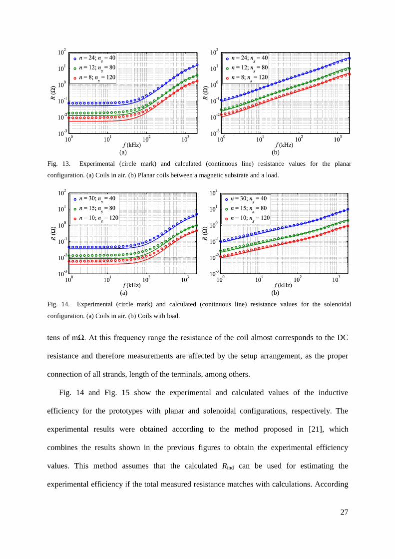
tens of mΩ. At this frequency range the resistance of the coil almost corresponds to the DC
resistance and therefore measurements are affected by the setup arrangement, as the proper
connection of all strands, length of the terminals, among others.
Fig. 14 and Fig. 15 show the experimental and calculated values of the inductive
efficiency for the prototypes with planar and solenoidal configurations, respectively. The
experimental results were obtained according to the method proposed in [21], which
combines the results shown in the previous figures to obtain the experimental efficiency
values. This method assumes that the calculated Rind can be used for estimating the
experimental efficiency if the total measured resistance matches with calculations. According
(a) (b)
Fig. 13. Experimental (circle mark) and calculated (continuous line) resistance values for the planar
configuration. (a) Coils in air. (b) Planar coils between a magnetic substrate and a load.
(a) (b)
Fig. 14. Experimental (circle mark) and calculated (continuous line) resistance values for the solenoidal
configuration. (a) Coils in air. (b) Coils with load.
Page 28
28
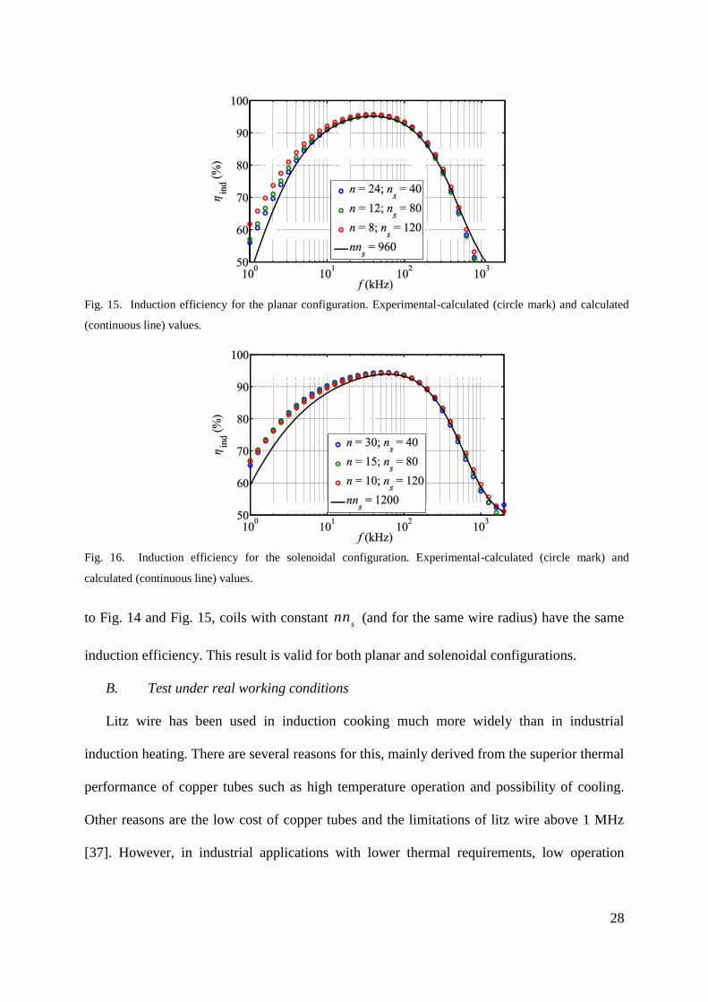
to Fig. 14 and Fig. 15, coils with constant s
nn (and for the same wire radius) have the same
induction efficiency. This result is valid for both planar and solenoidal configurations.
B. Test under real working conditions
Litz wire has been used in induction cooking much more widely than in industrial
induction heating. There are several reasons for this, mainly derived from the superior thermal
performance of copper tubes such as high temperature operation and possibility of cooling.
Other reasons are the low cost of copper tubes and the limitations of litz wire above 1 MHz
[37]. However, in industrial applications with lower thermal requirements, low operation
Fig. 15. Induction efficiency for the planar configuration. Experimental-calculated (circle mark) and calculated
(continuous line) values.
Fig. 16. Induction efficiency for the solenoidal configuration. Experimental-calculated (circle mark) and
calculated (continuous line) values.
Page 29
29
frequency or oriented to high efficiency performance, litz wire could compete with copper
tubes.
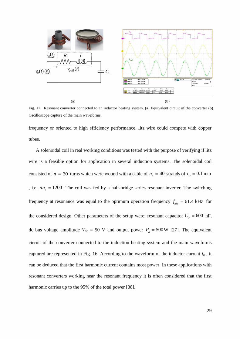
A solenoidal coil in real working conditions was tested with the purpose of verifying if litz
wire is a feasible option for application in several induction systems. The solenoidal coil
consisted of 30n turns which were wound with a cable of 40s
n strands of mm 0.1w
r
, i.e. 1200s
nn . The coil was fed by a half-bridge series resonant inverter. The switching
frequency at resonance was equal to the optimum operation frequency kHz 61.4optf for
the considered design. Other parameters of the setup were: resonant capacitor 600r
C nF,
dc bus voltage amplitude Vdc = 50 V and output power 500o
P W [27]. The equivalent
circuit of the converter connected to the induction heating system and the main waveforms
captured are represented in Fig. 16. According to the waveform of the inductor current io , it
can be deduced that the first harmonic current contains most power. In these applications with
resonant converters working near the resonant frequency it is often considered that the first
harmonic carries up to the 95% of the total power [38].
(a) (b)
Fig. 17. Resonant converter connected to an inductor heating system. (a) Equivalent circuit of the converter (b)
Oscilloscope capture of the main waveforms.
Page 30
30
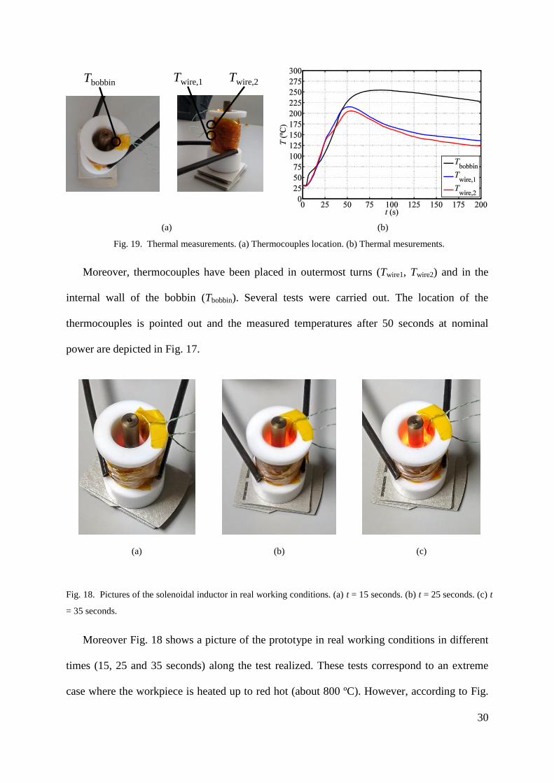
Moreover, thermocouples have been placed in outermost turns (Twire1, Twire2) and in the
internal wall of the bobbin (Tbobbin). Several tests were carried out. The location of the
thermocouples is pointed out and the measured temperatures after 50 seconds at nominal
power are depicted in Fig. 17.
Moreover Fig. 18 shows a picture of the prototype in real working conditions in different
times (15, 25 and 35 seconds) along the test realized. These tests correspond to an extreme
case where the workpiece is heated up to red hot (about 800 ºC). However, according to Fig.
(a) (b)
Fig. 19. Thermal measurements. (a) Thermocouples location. (b) Thermal mesurements.
Tbobbin Twire,1 Twire,2
(a) (b) (c)
Fig. 18. Pictures of the solenoidal inductor in real working conditions. (a) t = 15 seconds. (b) t = 25 seconds. (c) t
= 35 seconds.
Page 31
31
17 the temperature of both the copper and the bobbin is much lower. As it was commented in
the introduction, low-emissive materials for the bobbin help to not exceed the self-heating of
the windings.
V. CONCLUSION
This work presents an analysis of the efficiency of litz-wire induction heating systems
with respect to the frequency and geometry parameters (number of turns, number of strands
and wire radius). The analysis reveals that the induction efficiency could be maximized with
respect to the number of turns multiplied by the number of strands (which is equivalent to the
copper volume) for fixed frequency and strand diameter. Moreover, an optimization of the
induction efficiency with respect to the operation frequency for a given coil geometry is also
derived by means of a post-processing tool. Furthermore, strand radius selection criteria have
been provided and the optimum wire radius maximizing the inductive efficiency under
geometry restrictions is also investigated. Finally, several measurements have been carried
out in order to verify the proposed calculation method.
ACKNOWLEDGEMENT
This work was partly supported by the Spanish MINECO under Project TEC2013-42937-
R, Project CSD2009-00046, and Project RTC-2014-1847-6, by the FPU grant AP2010-4446,
by the DGA-FSE, by the University of Zaragoza under Project JIUZ-2014-TEC-08, and by
the BSH Home Appliances Group.
REFERENCES
[1] X. Wang, J. Tang, and L. Shi, "Induction heating of magnetic fluids for hyperthermia
treatment," IEEE Transactions on Magnetics, vol. 46, pp. 1043-1051, Apr. 2010.
[2] P. D. Barba, F. Dughiero, and E. Sieni, "Magnetic field synthesis in the design of
inductors for magnetic fluid hyperthermia," IEEE Transactions on Magnetics, vol. 46,
pp. 2931-2934, Aug. 2010.
Page 32
32
[3] H. N. Pham, H. Fujita, K. Ozaki, and N. Uchida, "Dynamic Analysis and Control for
Resonant Currents in a Zone-Control Induction Heating System," IEEE Transactions
on Power Electronics, vol. 28, pp. 1297-1307, Mar. 2013.
[4] F. Dughiero, M. Forzan, C. Pozza, and E. Sieni, "A Translational Coupled
Electromagnetic and Thermal Innovative Model for Induction Welding of Tubes,"
IEEE Transactions on Magnetics, vol. 48, pp. 483-486, Feb. 2012.
[5] H. N. Pham, H. Fujita, K. Ozaki, and N. Uchida, "Phase angle control of high-
frequency resonant currents in a multiple inverter system for zone-control induction
heating," IEEE Transactions on Power Electronics, vol. 26, pp. 3357-3366, Nov.
2011.
[6] J. Acero, C. Carretero, O. Lucia, R. Alonso, and J. M. Burdio, "Mutual Impedance of
Small Ring-Type Coils for Multiwinding Induction Heating Appliances," IEEE
Transactions on Power Electronics, vol. 28, pp. 1025-1035, Feb. 2013.
[7] C. R. Sullivan and L. Beghou, "Design methodology for a high-Q self-resonant coil
for medical and wireless-power applications," in Control and Modeling for Power
Electronics (COMPEL), 2013 IEEE 14th Workshop on, 2013, pp. 1-8.
[8] M. Bartoli, A. Reatti, and M. K. Kazimierczuk, "Minimum copper and core losses
power inductor design " presented at the Thirty-First Industry Applications Annual
Meeting Conference, IAS '96, San Diego, CA, 1996.
[9] H. Rossmanith, M. Doebroenti, M. Albach, and D. Exner, "Measurement and
characterization of high frequency losses in nonideal litz wires," IEEE Transactions
on Power Electronics, vol. 26, pp. 3386-3394, Nov. 2011.
[10] R. P. Wojda and M. K. Kazimierczuk, "Winding resistance of litz-wire and multi-
strand inductors," IET Electric Power Applications, vol. 5, pp. 257-268, 2012.
[11] H. Hamalainen, J. Pyrhonen, J. Nerg, and J. Talvitie, "AC Resistance Factor of Litz-
Wire Windings Used in Low-Voltage High-Power Generators," IEEE Transactions on
Industrial Electronics, vol. 61, pp. 693-700, Feb. 2014.
[12] D. C. Meeker, "An improved continuum skin and proximity effect model for
hexagonally packed wires," Journal of Computational and Applied Mathematics, vol.
236, pp. 4635-4644, 2012.
[13] C. R. Sullivan, "Computationally efficient winding loss calculation with multiple
windings, arbitrary waveforms, and two-dimensional or three-dimensional field
geometry," IEEE Transactions on Power Electronics, vol. 16, pp. 142-150, Jan. 2001.
[14] C. R. Sullivan, "Optimal choice for number of strands in a litz-wire transformer
winding," IEEE Transactions on Power Electronics, vol. 14, pp. 283-291, Mar. 1999.
[15] C. R. Sullivan, "Cost-constrained selection of strand diameter and number in a litz-
wire transformer winding," IEEE Transactions on Power Electronics, vol. 16, pp.
281-288, Mar. 2001.
[16] J. D. Pollock, T. Abdallah, and C. R. Sullivan, "Easy-to-use CAD tools for litz-wire
winding optimization," in Applied Power Electronics Conference and Exposition,
2003. APEC '03. Eighteenth Annual IEEE, 2003, pp. 1157-1163.
[17] C. R. Sullivan and R. Y. Zhang, "Simplified design method for litz wire," in Applied
Power Electronics Conference and Exposition (APEC), 2014 Twenty-Ninth Annual
IEEE, 2014, pp. 2667-2674.
[18] A. Stadler, "The optimization of high frequency inductors with litz-wire windings,"
presented at the The 8th International Conference on Compatibility and Power
Electronics (CPE), 2013, Ljubljana, 2013.
[19] J. Acero, R. Alonso, J. M. Burdío, L. A. Barragán, and D. Puyal, "Frequency-
dependent resistance in litz-wire planar windings for domestic induction heating
appliances," IEEE Transactions on Power Electronics, vol. 21, pp. 856-866, 2006.
Page 33
33
[20] G. Cerri, S. A. Kovyryalov, and V. M. Primiani, "Modelling of a Litz-wire planar
winding geometry for an accurate reactance evaluation," Science, Measurement &
Technology, IET, vol. 4, pp. 214-219, July 2010.
[21] J. Acero, C. Carretero, R. Alonso, and J. M. Burdío, "Quantitative evaluation of
induction efficiency in domestic induction heating applications," IEEE Trans. on
Magnetics, vol. 49, pp. 1382-1389, Apr. 2013.
[22] J. Acero, J. M. Burdío, L. A. Barragán, D. Navarro, R. Alonso, J. R. García, F.
Monterde, P. Hernández, S. Llorente, and I. Garde, "Domestic induction appliances,"
IEEE Industry Applications Magazine, vol. 16, pp. 39-47, March/April 2010.
[23] O. Lucia, J. Acero, C. Carretero, and J. M. Burdio, "Induction Heating Appliances:
Toward More Flexible Cooking Surfaces," IEEE Industrial Electronics Magazine, vol.
7, pp. 35-47, Sept. 2013.
[24] I. Lope, C. Carretero, J. Acero, R. Alonso, and J. M. Burdio, "Frequency-Dependent
Resistance of Planar Coils in Printed Circuit Board With Litz Structure," IEEE
Transactions on Magnetics, vol. 50, pp. 1-9, 2014.
[25] I. Lope, C. Carretero, J. Acero, R. Alonso, and J. M. Burdio, "AC power losses model
for planar windings with rectangular cross-sectional conductors," IEEE Transactions
on Power Electronics, vol. 29, pp. 23-28, Jan. 2014.
[26] C. Feeney, N. Wang, S. C. OMathuna, and M. Duffy, "A 20-MHz 1.8-W DC-DC
Converter With Parallel Microinductors and Improved Light-Load Efficiency," IEEE
Transactions on Power Electronics, vol. 30, pp. 771-779, 2015.
[27] H. Sarnago, O. Lucia, A. Mediano, and J. M. Burdio, "Analytical Model of the Half-
Bridge Series Resonant Inverter for Improved Power Conversion Efficiency and
Performance," IEEE Transactions on Power Electronics, vol. 30, pp. 4128-4143, Aug
2015.
[28] C. Carretero, O. Lucia, J. Acero, and J. M. Burdio, "Computational Modeling of Two
Partly Coupled Coils Supplied by a Double Half-Bridge Resonant Inverter for
Induction Heating Appliances," Industrial Electronics, IEEE Transactions on, vol. 60,
pp. 3092-3105, Aug. 2013.
[29] J. A. Ferreira, Electromagnetic Modelling of Power Electronics converters. Norwell,
MA: Kluwer, 1989.
[30] C. Carretero, J. Acero, and R. Alonso, "TM-TE decomposition of power losses in
multi-stranded litz-wires used in electronic devices," Progress In Electromagnetic
Research, vol. 123, pp. 83-103, Dec. 2012.
[31] J. Gyselinck and P. Dular, "Frequency-domain homogenization of bundles of wires in
2-D magnetodynamic FE calculations," IEEE Transactions on Magnetics, vol. 41, pp.
1416-1419, May 2005.
[32] X. Nan and C. R. Sullivan, "An improved calculation of proximity-effect loss in high-
frequency windings of round conductors," presented at the 2003 IEEE 34th Annual
Power Electronics Specialist Conference, 2003. PESC '03, 2003.
[33] X. Nan and C. R. Sullivan, "Simplified high-accuracy calculation of eddy-current loss
in round-wire windings," presented at the 2004 IEEE 35th Annual Power Electronics
Specialists Conference, 2004. PESC 04, 2004.
[34] R. P. Wojda and M. K. Kazimierczuk, "Analytical optimization of solid-round-wire
windings," IEEE Transactions on Industrial Electronics, vol. 60, pp. 1033-1041, Mar.
2013.
[35] M. K. Kazimierczuk, High Frequency Magnetic Components, 2nd ed. New York:
John Wiley and Sons, 2009.
[36] W. G. Hurley and W. H. Wölfle, Transformers and Inductors for Power Electronics.
Theory, Design and Applications. United Kingdom: John Wiley & Sons,, 2013.
Page 34
34
[37] C. R. Sullivan, "Layered foil as an alternative to litz wire: Multiple methods for equal
current sharing among layers," in 2014 IEEE 15th Workshop on Control and Modeling
for Power Electronics (COMPEL), 2014, pp. 1-7.
[38] J. Jordan, V. Esteve, E. Sanchis-Kilders, E. J. Dede, E. Maset, J. B. Ejea, and A.
Ferreres, "A comparative performance study of a 1200 V Si and SiC MOSFET
intrinsic diode on an induction heating inverter," IEEE Transactions on Power
Electronics, vol. 29, pp. 2550-2562, 2014.