July 2017 1 GasPro Compression BTEX VRU for Energy Efficiency and Emissions Reduction Analysis and Reporting of a Trial of GasPro Compression BTEX VRU for Energy Efficiency and Emissions Reduction Final Report – Rev 1 For Petroleum Technology Alliance Canada July 2017 With the financial support of:
Transcript
July 2017 1
GasPro Compression BTEX VRU for Energy Efficiency and Emissions Reduction
Analysis and Reporting of a Trial of
GasPro Compression BTEX VRU for Energy Efficiency and Emissions Reduction
Final Report – Rev 1
For Petroleum Technology Alliance Canada
July 2017
With the financial support of:
July 2017 2
GasPro Compression BTEX VRU for Energy Efficiency and Emissions Reduction
Executive Summary
Benzene emissions from glycol dehydration units are regulated in Western Canada. In addition, Alberta has initiated a methane emission reduction plan for the oil and gas sector. The major challenge in reducing emissions from dehydration systems is designing systems to capture the gas from the flash tank vent and still column (glycol regenerator) overheads. The still column operates at atmospheric conditions and the vented gas is wet; this leads to additional effort to design a system to handle wet vapour at low pressures.
Several technologies have been proposed to reduce BTEX emissions (benzene, toluene, ethylbenzene, xylenes) from glycol dehydration units, such as combustion (flare/incinerator), Kenilworth combustion, SlipStream, JATCO BTEX Eliminator, vapour recovery units (VRU), and condensing tanks (such as TankSafe). GasPro Compression Corp. has recently developed a vapour recovery unit to reduce/eliminate BTEX emissions from glycol dehydration plants. The GasPro BTEX VRU unit addressed in this study has been installed as a trial unit at a dehydration facility in Central Alberta since February 2016. This report presents the results obtained between December 2016 and June 2017 from the data collection, engineering simulation and modelling of the dehydration plant and GasPro BTEX VRU unit as well as a leak survey done by GreenPath Energy. The objective of the study is to determine the GasPro VRU technology emissions reduction efficiency and to investigate the benefits and challenges of the technology.
Aspen HYSYS v7.0 and EPA TANKS 4.0.9d were used for emissions calculations including methane and BTEX emissions from the installed VRU and the facility produced water tank. The leak survey was done by FLIR optical gas imaging camera technology along with a Hi-Flow sampler to detect and estimate volumes of potential leaks from the GasPro VRU and other parts of the facility.
Referring to calculations and observations, we found that the potential BTEX and GHG emissions reduction using the GasPro BTEX VRU is 100%. However, there are two potential sources of emissions which may lead to reductions in the overall efficiency: the emissions from the produced water storage tank and fugitive emissions. The flashing, working and breathing losses from the produced water tank calculated for this project result in zero emissions due to the large amount of produced water collected from the facility. However, fugitive emissions were detected from the GasPro VRU during the site visit due to a leaking PRV (pressure relief valve) with high fugitive emission rate. This led to emissions reduction efficiencies less than 100%: 89.9% for methane and GHGs and 97% for benzene. Subsequent to the initial study, the PRV was replaced with a model from a different manufacturer and the unit was surveyed again, and found to have no leaks and hence zero BTEX and GHG emissions from the dehydration unit and GasPro BTEX VRU.
In general, to establish the reduction efficiency from any VRU system we would recommended taking into account the emissions from condensed water tanks as a result of flashing, working and breathing losses. Alternately, connecting the water tank vent to the VRU system to collect all emissions would ensure complete control. As with other equipment in an upstream facility, we would also recommend scheduled leak surveys for the VRU.
VRUs such as the Gas Pro VRU also provide an energy efficiency benefit in addition to reducing emissions, as the recovered gas is compressed and recycled as fuel versus being vented to atmosphere or simply burned in a flare or incinerator. Other emissions reduction technologies such as flaring and incineration do not immediately provide this energy conservation benefit.
As per field operators’ feedback, the GasPro technology is simple to understand and reliable compared to alternative technologies and they felt that this GasPro VRU technology was more robust and required virtually no operator intervention.
July 2017 3
GasPro Compression BTEX VRU for Energy Efficiency and Emissions Reduction
Table of Contents Executive Summary ..........................................................................................................................2
Appendix A .................................................................................................................................... 21
Appendix B ..................................................................................................................................... 22
July 2017 4
GasPro Compression BTEX VRU for Energy Efficiency and Emissions Reduction
Introduction
Glycol dehydration is a process to remove water from natural gas and prevent corrosion and hydrate formation in pipelines. In the dehydration process, glycols such as triethylene glycol (TEG) or diethylene glycol (DEG) are used to absorb water from wet natural gas in a contactor. In addition to water, glycol will also absorb small quantities of hydrocarbons including benzene, toluene, ethylbenzene, and xylenes (known as BTEX), methane, and volatile hydrocarbons (VOCs) from the natural gas. The glycol mixture leaving the contactor, known as rich glycol, is then regenerated by boiling off the absorbed water and is used again in the dehydration process. Some of the absorbed hydrocarbons are also released during the regeneration process. Government regulations restrict the emissions of some of the toxic hydrocarbon components such as benzene from dehydrators (Benzene is a Group I carcinogen). In addition, there is increased focus on new regulations for reducing methane and Greenhouse Gas (GHG) emissions which are also released during regeneration. The benzene and light hydrocarbons leaving the regenerator are difficult to capture as they are low pressure, wet vapours, thus making it difficult to reduce emissions from the regenerator.
There are several methods accepted by regulators to reduce emissions from the regenerator (or still column) such as condenser tanks (e.g. TankSafe), flares, incinerators, vapour recovery units (VRUs), Burner Technology, etc. GasPro Compression Corp. has developed a VRU technology called GasPro BTEX VRU. For this BTEX VRU technology, still column overheads are first cooled in the GasPro Cooler (an air cooler), then separated, with the uncondensed vapour routed to the GasPro compressor which re-injects the gas at the inlet of the facility.
In principle, this VRU technology can provide 100% reduction of emissions (and Directive 39 supports this 100% reduction). In some cases, VRUs have operational challenges, and the 100% reduction may not be a reality due to downtime, as well as potential unanticipated BTEX emissions, either from leaks or from liquid tank emissions.
The GasPro VRU in this study has been installed at a dehydration plant in central Alberta since February 2016 as a trial and its performance has been monitored by field operators during the operating period. This study, initiated by Petroleum Technology Alliance Canada (PTAC) is designed to analyze the results of the GasPro BTEX VRU trial with respect to emissions reductions at glycol dehydration facilities and energy efficiency. The study was conducted from December 2016 to June 2017 by the Contractors Process Ecology and GreenPath Energy.
Process Ecology is an engineering software and consulting company with extensive experience in simulating glycol dehydration facilities and associated equipment, as well as estimating and reporting emissions from oil and gas facilities. For this project, the modelling and simulation, process case studies, and estimation of emissions from the facility of interest have been done by Process Ecology.
GreenPath is a market leader in providing infrared fugitive emission detection for the oil and gas and petrochemical industries and specializes in emission measurement and reduction solutions. As part of the study, the identification of leaks from the GasPro BTEX VRU and the entire dehydration facility have been done by GreenPath.
The Contractors participated in a site visit in February 2017 to collect operating conditions required for modelling, to identify potential leaks (or other issues), and to communicate with and obtain feedback from operating personnel. Process Ecology requested collection and analysis of
July 2017 5
GasPro Compression BTEX VRU for Energy Efficiency and Emissions Reduction
samples from key parts of the process including the inlet separator, produced water tank and GasPro inlet scrubber. The operating data and analyses have been used as inputs to a HYSYS process simulator model (v7.0) and EPA TANKS software model (v4.0.9d) to determine the emissions from the facility.
It should be noted that the operating company’s participation was voluntary and confidential and the company name and location are not provided.
Project Objectives
The objective of this study is to answer some key questions about the GasPro BTEX VRU technology:
- What are the benefits (technical, environmental, economic) of the technology? - Is the technology operationally reliable? - Are there elements of the technology which in practice result in unanticipated emissions? - What are the maintenance and operational challenges with the GasPro VRU? Is it an
improvement on other VRU technology, and if so, why? - What are the costs associated with the technology (capital and operational)?
To achieve the objective, the information and data gathered at the site have been used for quantification of emissions as well as an independent assessment of the technology benefits and challenges.
GasPro Compression BTEX VRU Technology
GasPro Compression Corp. (GasPro) has developed the BTEX VRU technology for controlling BTEX emissions reduction from glycol regenerator overheads in a dehydration facility. The schematic diagram of the VRU installed at the dehydration facility is shown in Figure 1.
Figure 1- Simplified Schematic of GasPro BTEX VRU
July 2017 6
GasPro Compression BTEX VRU for Energy Efficiency and Emissions Reduction
As shown in the figure, the still column overheads from the two dehydration units are combined and directed to the GasPro BTEX Air Cooler (E-900) where the overheads are cooled and condensed to liquid (mostly water). The liquid is then sent to the GasPro Scrubber (V-900). In the scrubber, the condensed liquid is separated from the uncondensed vapour and the liquid is then sent to the facility’s produced water storage tank via two gear pumps (P-900/901). The uncondensed vapour from the scrubber is routed to the GasPro reciprocating compressor (K-900) to increase the pressure of the vapour stream so that it can be pushed into the suction of the facility overhead compressor and eventually recycled to the inlet of the facility. The compressed vapour from the GasPro BTEX VRU is cooled in After Cooler (E-901) to remove the heat of compression before being directed to the suction of the facility overhead compressor.
The GasPro technology recompresses and recycles the still gas vent, eliminating the emissions of BTEX from still columns in dehydration systems. However, the emissions from the condensed liquid for the GasPro inlet scrubber which is sent to the facility water tank must be measured and/or estimated since the water tank is not tied into the VRU, but is vented to atmosphere – presenting a possible benzene air emission source. There is a possibility that the non-condensable gases dissolved in the condensed liquid and quantities of condensed BTEX are emitted from the water tank, particularly when the ambient temperature is high. The effect of ambient temperature on benzene emissions from the water tank will be discussed later in this study.
This study also aims to identify any other potential leak points in the process that may result in unintended emissions.
Conventional Vapour Recovery Units vs. GasPro BTEX VRU
Similar to the GasPro BTEX VRU, the final goal of conventional vapour recovery units (VRUs) is to reduce methane, VOCs and BTEX emissions from flash tank separators and still columns by recompressing still column overheads and recycling them to the facility inlet gas compressor suction. However, there are some differences between the GasPro BTEX VRU and conventional VRUs.
Conventional VRU units used in dehydration facilities consist of a still column vent cooler, still column vent tank, VRU scrubber(s), VRU compressor and after cooler(s). In the GasPro VRU technology, the need for a still vent tank is eliminated and replaced by an air-cooler to properly cool the vapour stream. This potentially results in lower capital cost and a correspondingly shorter payback period than a conventional VRU. Using a properly sized air-cooled heat-exchanger helps to control the cooling process and enhance vapour condensation and thus leads to a higher BTEX reduction efficiency than still vent tanks. The compressor types most commonly used for VRUs are either flooded rotary screws or rotary sliding vanes. A reciprocating compressor is used instead for the GasPro VRU which has the advantage of enabling higher discharge pressures. Table 1 shows the operating ranges of different compressor types typically used in VRUs. As noted by GasPro Compression Corp., the equipment and maintenance costs of reciprocating compressors are often lower than other types of VRU compressors, especially because operations personnel are generally more familiar with reciprocating compressors, have associated maintenance training, and replacement equipment is usually more readily available.
July 2017 7
GasPro Compression BTEX VRU for Energy Efficiency and Emissions Reduction
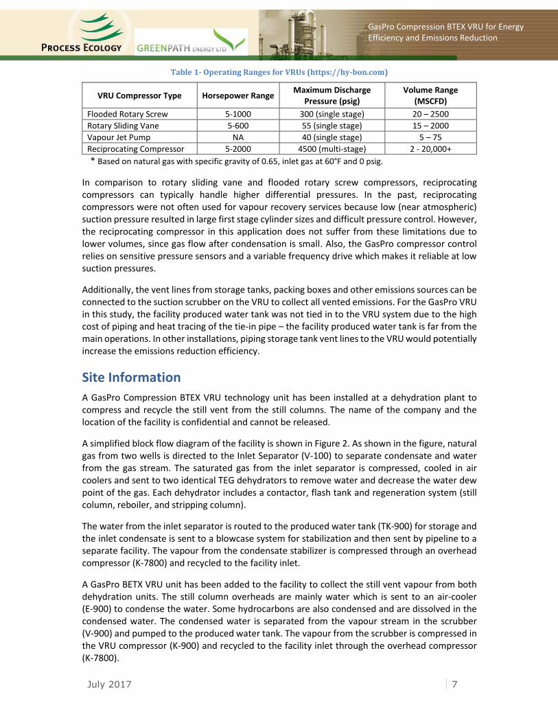
Table 1- Operating Ranges for VRUs (https://hy-bon.com)
VRU Compressor Type Horsepower Range Maximum Discharge
* Based on natural gas with specific gravity of 0.65, inlet gas at 60°F and 0 psig.
In comparison to rotary sliding vane and flooded rotary screw compressors, reciprocating compressors can typically handle higher differential pressures. In the past, reciprocating compressors were not often used for vapour recovery services because low (near atmospheric) suction pressure resulted in large first stage cylinder sizes and difficult pressure control. However, the reciprocating compressor in this application does not suffer from these limitations due to lower volumes, since gas flow after condensation is small. Also, the GasPro compressor control relies on sensitive pressure sensors and a variable frequency drive which makes it reliable at low suction pressures.
Additionally, the vent lines from storage tanks, packing boxes and other emissions sources can be connected to the suction scrubber on the VRU to collect all vented emissions. For the GasPro VRU in this study, the facility produced water tank was not tied in to the VRU system due to the high cost of piping and heat tracing of the tie-in pipe – the facility produced water tank is far from the main operations. In other installations, piping storage tank vent lines to the VRU would potentially increase the emissions reduction efficiency.
Site Information
A GasPro Compression BTEX VRU technology unit has been installed at a dehydration plant to compress and recycle the still vent from the still columns. The name of the company and the location of the facility is confidential and cannot be released.
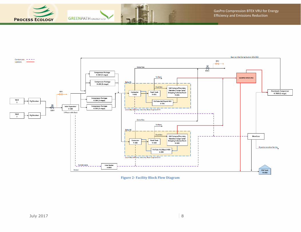
A simplified block flow diagram of the facility is shown in Figure 2. As shown in the figure, natural gas from two wells is directed to the Inlet Separator (V-100) to separate condensate and water from the gas stream. The saturated gas from the inlet separator is compressed, cooled in air coolers and sent to two identical TEG dehydrators to remove water and decrease the water dew point of the gas. Each dehydrator includes a contactor, flash tank and regeneration system (still column, reboiler, and stripping column).
The water from the inlet separator is routed to the produced water tank (TK-900) for storage and the inlet condensate is sent to a blowcase system for stabilization and then sent by pipeline to a separate facility. The vapour from the condensate stabilizer is compressed through an overhead compressor (K-7800) and recycled to the facility inlet.
A GasPro BETX VRU unit has been added to the facility to collect the still vent vapour from both dehydration units. The still column overheads are mainly water which is sent to an air-cooler (E-900) to condense the water. Some hydrocarbons are also condensed and are dissolved in the condensed water. The condensed water is separated from the vapour stream in the scrubber (V-900) and pumped to the produced water tank. The vapour from the scrubber is compressed in the VRU compressor (K-900) and recycled to the facility inlet through the overhead compressor (K-7800).
July 2017 8
GasPro Compression BTEX VRU for Energy Efficiency and Emissions Reduction
Figure 2- Facility Block Flow Diagram
July 2017 9
GasPro Compression BTEX VRU for Energy Efficiency and Emissions Reduction
Site Visit and Operational Data Collection
The Contractors (Process Ecology and GreenPath) participated in a site visit on February 9, 2017 to collect operating conditions required for modelling, to identify potential leaks (or other issues), and to communicate with operating personnel and obtain feedback on the performance of the GasPro BTEX VRU.
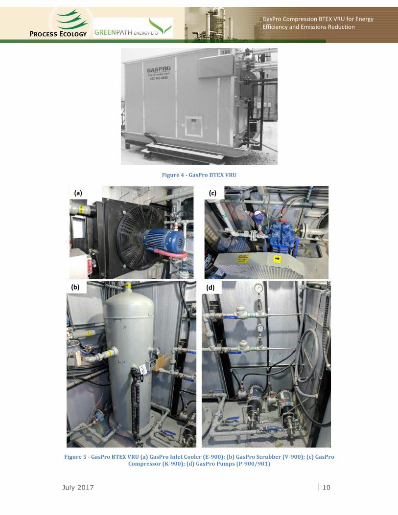
Figure 3 shows the two TEG dehydration units where the still column overheads are connected to the GasPro BTEX VRU. The GasPro VRU building and the main equipment inside the building are shown in Figures 4-5. The condensed water from the scrubber is pumped to the facility produced water tank which is shown in Figure 6.
Figure 3 - Two Dehydration Units with Still Overheads Piped to GasPro BTEX VRU
Connection to GasPro BTEX VRU
July 2017 10
GasPro Compression BTEX VRU for Energy Efficiency and Emissions Reduction
GasPro Compression BTEX VRU for Energy Efficiency and Emissions Reduction
Figure 6 - Methanol and Produced Water Storage Tanks
During the site visit, the operating conditions for key parts of the process were also collected and are summarized in Table 2. Samples from main process streams including the inlet separator (gas, condensate, and water), produced water tank, and GasPro scrubber water stream were collected and analysed. The analyses are listed in Tables 3-6.
Table 2- Operating Conditions
Parameter Data
Inlet separator temperature (°C) 0
Inlet separator pressure (kPag) 668.2
Inlet gas flow (e3m3/day) 510.39
Stabilized condensate flow (m3/day) 10.6
Produced water flow (m3/day) 5.4
Contactor temperature (°C) 27.2
Contactor pressure (kPag) 6582
Glycol circulation rate (L/min) 3
Flash tank temperature (°C) 41.5
Flash tank pressure (kPag) 345
Reboiler temperature (°C) 200
Stripping gas* (scfm) 1.5
Condensate stabilizer temperature (°C) 40
Condensate stabilizer pressure (kPag) 2068
GasPro scrubber temperature (°C) 11
GasPro scrubber pressure (kPag) 1.185
GasPro compressor discharge pressure (kPag) 341
Produced water tank temperature (°C) -4
* Mixture of flash tank vent and fuel gas
July 2017 12
GasPro Compression BTEX VRU for Energy Efficiency and Emissions Reduction
Table 3 - Gas Analyses
Components Inlet Separator Gas
(mole fraction) Inlet Gas to Dehy
(mole fraction)
H2 Trace Trace
He 0.0001 0.0001
N2 0.0024 0.0021
CO2 0.0123 0.0125
H2S 0.0000 0.0000
C1 0.8916 0.8908
C2 0.0631 0.0632
C3 0.0182 0.0181
iC4 0.0030 0.0030
nC4 0.0041 0.0045
iC5 0.0015 0.0016
nC5 0.0013 0.0012
C6+ 0.0024 0.0029
Benzene 0.00014 0.00019
Toluene 0.00009 0.00018
Ethylbenzene Trace 0.00001
Xylenes 0.00003 0.00004
124-Trimethylbenzene Trace Trace
Table 4 - Condensate Analysis
Components Inlet Separator Condensate
(mole fraction)
N2 0.0004
CO2 0.0014
H2S 0.0000
C1 0.0369
C2 0.0165
C3 0.0188
iC4 0.0100
nC4 0.0267
iC5 0.0341
nC5 0.0414
C6 0.1102
C7+ 0.7036
Benzene 0.0178
Toluene 0.0555
Ethylbenzene 0.0046
Xylenes 0.0094
124-Trimethylbenzene 0.0061
July 2017 13
GasPro Compression BTEX VRU for Energy Efficiency and Emissions Reduction
Table 5 - Water Analyses
Components Inlet Separator Water
(Mass PPM) Produced Water tank
(Mass PPM)
C1 <1 <1
C2 1 <1
C3 1 <1
iC4 13 8
nC4 4 5
iC5 1 <1
nC5 1 1
C6+ 1699 <1
Benzene 1 <1
Toluene 2 <1
Ethylbenzene 2 <1
Xylenes 14 <1
124-Trimethylbenzene 4 <1
Table 6 - GasPro Scrubber (V-900) Water Analysis
Components GasPro Scrubber Water
(g/m3)
GasPro Scrubber Water (Mass PPM) *
C6-C10 45,000,0000 45,000
Benzene 4,500,000 4,500
Toluene 3,100,000 3,100
Ethylbenzene 580,000 580
Xylenes 5,100,000 5,100
124-Trimethylbenzene 5,000,000 5,000
* based on mass density of 1000 kg/m3
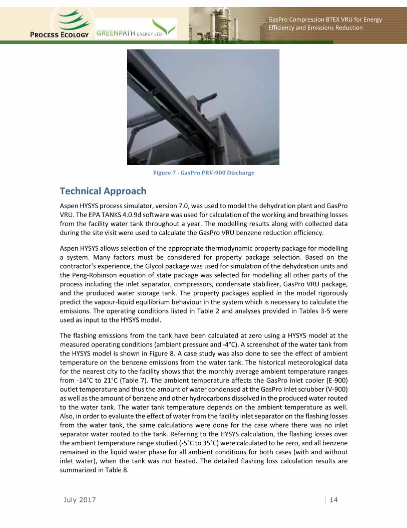
In addition to data gathering, a leak detection survey was completed by GreenPath during the site visit. The initial leak survey report for the GasPro BTEX VRU is presented in Appendix A and a description of the method of the survey is found in Appendix B. The initial survey indicated a leak of 0.26 cfm of methane from the GasPro inlet suction scrubber pressure relief valve (PRV-900) being vented to atmosphere (Figure 7). As there is no low-pressure flare at the facility, the PRV-900 discharge is routed to atmosphere (there is only a high-pressure flare at the facility). An attempt was made by operations and GasPro personnel during the site visit to inspect the PRV and fix the leak; however, the PRV was found to be in “as new” condition, thus an immediate repair was not possible. In June 2017, this leak was eliminated. The faulty PRV (Enardo) was replaced with a different model from a different manufacturer (Prism Popa Vapour Tight Vent). A repeat leak survey was done by GreenPath and the unit was confirmed to be free of leaks. The leak survey also detected other leaks in other parts of the facility such as compressor packings and compressor lube oil pumps which are not in the scope of this project and which have no bearing on the study results, thus the findings are not included in this report.
July 2017 14
GasPro Compression BTEX VRU for Energy Efficiency and Emissions Reduction
Figure 7 - GasPro PRV-900 Discharge
Technical Approach
Aspen HYSYS process simulator, version 7.0, was used to model the dehydration plant and GasPro VRU. The EPA TANKS 4.0.9d software was used for calculation of the working and breathing losses from the facility water tank throughout a year. The modelling results along with collected data during the site visit were used to calculate the GasPro VRU benzene reduction efficiency.
Aspen HYSYS allows selection of the appropriate thermodynamic property package for modelling a system. Many factors must be considered for property package selection. Based on the contractor’s experience, the Glycol package was used for simulation of the dehydration units and the Peng-Robinson equation of state package was selected for modelling all other parts of the process including the inlet separator, compressors, condensate stabilizer, GasPro VRU package, and the produced water storage tank. The property packages applied in the model rigorously predict the vapour-liquid equilibrium behaviour in the system which is necessary to calculate the emissions. The operating conditions listed in Table 2 and analyses provided in Tables 3-5 were used as input to the HYSYS model.
The flashing emissions from the tank have been calculated at zero using a HYSYS model at the measured operating conditions (ambient pressure and -4°C). A screenshot of the water tank from the HYSYS model is shown in Figure 8. A case study was also done to see the effect of ambient temperature on the benzene emissions from the water tank. The historical meteorological data for the nearest city to the facility shows that the monthly average ambient temperature ranges from -14°C to 21°C (Table 7). The ambient temperature affects the GasPro inlet cooler (E-900) outlet temperature and thus the amount of water condensed at the GasPro inlet scrubber (V-900) as well as the amount of benzene and other hydrocarbons dissolved in the produced water routed to the water tank. The water tank temperature depends on the ambient temperature as well. Also, in order to evaluate the effect of water from the facility inlet separator on the flashing losses from the water tank, the same calculations were done for the case where there was no inlet separator water routed to the tank. Referring to the HYSYS calculation, the flashing losses over the ambient temperature range studied (-5°C to 35°C) were calculated to be zero, and all benzene remained in the liquid water phase for all ambient conditions for both cases (with and without inlet water), when the tank was not heated. The detailed flashing loss calculation results are summarized in Table 8.
July 2017 15
GasPro Compression BTEX VRU for Energy Efficiency and Emissions Reduction
Figure 8 - Water Tank (Aspen HYSYS model)
Table 7 - Meteorological monthly data for the nearest city to the facility
Month Minimum
Temperature (˚C) Maximum
Temperature (˚C) Average Wind Speed
(m/s) Average Solar Insolation
(kW/m2/day)
January -12 -3 1.9 0.93
February -7 2 2.5 1.80
March -5 5 2.2 3.20
April 2 14 3.1 4.46
May 2 16 2.7 5.09
June 7 20 2.7 5.33
July 9 21 2.1 5.38
August 10 21 2.6 4.61
September 4 15 2.6 3.33
October -2 5 1.9 2.06
November -2 4 1.6 1.14
December -14 -9 3.4 0.66
Table 8 - Produced Water Tank Flashing Losses at Different Ambient Temperatures
Tank Temperature (˚C) *
GasPro Inlet Scrubber Temperature (˚C) **
Tank Flashing Losses (with inlet water)
(m3/day)
Tank Flashing Losses (without inlet water)
(m3/day)
-5 5 0 0
0 5 0 0
5 10 0 0
10 15 0 0
15 20 0 0
20 25 0 0
25 30 0 0
30 35 0 0
35 40 0 0
* Assumed minimum tank temperature is -5 ˚C ** Assumed 5 °C minimum approach to ambient temperature for the GasPro inlet air-cooler
with minimum inlet temperature at +5 °C (due to heat in GasPro building).
July 2017 16
GasPro Compression BTEX VRU for Energy Efficiency and Emissions Reduction
At lower ambient temperatures, more liquids are condensed at the GasPro inlet scrubber; at the tank, the bubble point of the liquid is still higher than the ambient temperature, and there are no emissions from the water tank. On the other hand, at higher ambient temperatures, less liquid is condensed at the scrubber and the bubble point of the liquid again remains above the higher ambient temperature. Therefore, in this case the flashing losses are zero for both cases.
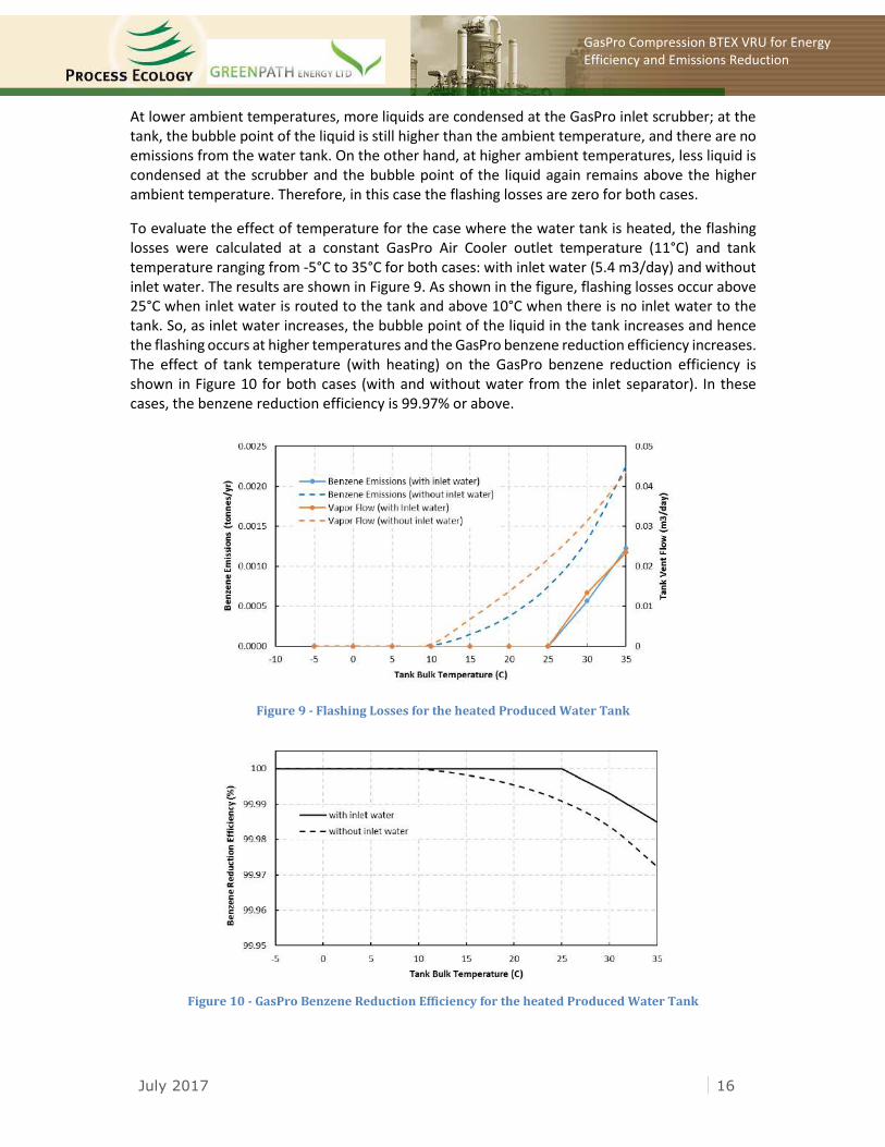
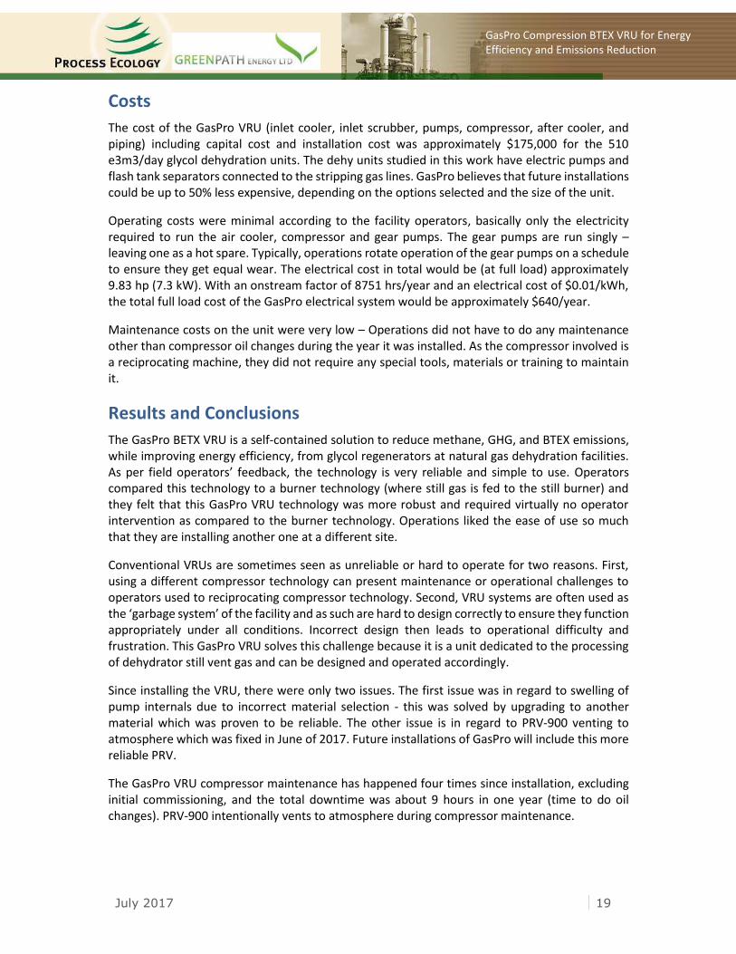
To evaluate the effect of temperature for the case where the water tank is heated, the flashing losses were calculated at a constant GasPro Air Cooler outlet temperature (11°C) and tank temperature ranging from -5°C to 35°C for both cases: with inlet water (5.4 m3/day) and without inlet water. The results are shown in Figure 9. As shown in the figure, flashing losses occur above 25°C when inlet water is routed to the tank and above 10°C when there is no inlet water to the tank. So, as inlet water increases, the bubble point of the liquid in the tank increases and hence the flashing occurs at higher temperatures and the GasPro benzene reduction efficiency increases. The effect of tank temperature (with heating) on the GasPro benzene reduction efficiency is shown in Figure 10 for both cases (with and without water from the inlet separator). In these cases, the benzene reduction efficiency is 99.97% or above.
Figure 9 - Flashing Losses for the heated Produced Water Tank
Figure 10 - GasPro Benzene Reduction Efficiency for the heated Produced Water Tank
July 2017 17
GasPro Compression BTEX VRU for Energy Efficiency and Emissions Reduction
The EPA TANKS 4.0.9d software estimates working and breathing losses from storage tanks. The breathing losses occur due to changes in ambient temperature and the working losses occur due to agitation of the liquid during tank filling or emptying operations, as liquid clings to the exposed surface area in the tank and eventually evaporates. The TANKS software is based on AP-42 methodologies - a standard for emission calculations. The sampled water tank analysis (Table 5) including water, n-butane, i-butane, n-pentane, benzene, methylcyclopentane, cyclohexane, methylcyclohexane, toluene, ethylbenzene, and xylenes was used for the emissions calculation. The input data listed in Table 9 was used to calculate working and breathing losses.
Water, n-butane, and i-butane are not a native part of the TANKS software chemical database. Therefore, to perform the calculation, they were added to the chemical database1,2 and the emissions were calculated on monthly basis. The emissions results show that the tank losses are mainly water with a trace of butanes and all benzene remains in the liquid phase. The calculated monthly emissions from the tank are summarized in Table 10.
Table 9 - Input Data Used in TANKS 4.0.9d for Working and Breathing Losses
Parameters Value
Tank water analysis Composition from Table 5 as sampled
Type of tank Vertical fixed roof tank
Meteorological data Data listed in Table 7
Shell height (ft) 21
Shell diameter (ft) 11.67
Max. liquid height (ft) 15.5
Average liquid height (ft) 5.5
Water flowrate (m3/day) 5.4
Shell and roof colour White
Shell and roof condition Good
Roof type Cone
Roof height (ft) 0.367
Roof slope (ft/ft) 0.0625
Vacuum setting (psig) -0.03
Pressure setting (psig) 0.03
Average atmospheric pressure (kPa) 89
1 U.S. Environmental Protection Agency (September 1999) “User’s Guide to TANKS, Storage Tank Emissions Calculation Software Version 4.0”. 2 Texas Commission on Environmental Quality, “Determining Emissions from Produced Water Storage Tanks”
July 2017 18
GasPro Compression BTEX VRU for Energy Efficiency and Emissions Reduction
Table 10 - Produced Water Tank (TK-900) Breathing and Working Losses from TANKS 4.0.9d
Month Breathing Losses
(kg) Working Losses
(kg) Total Losses
(kg)
Composition (Mass %) *
Water iC4 nC4
January 0.156 0.622 0.778 99.70 0.21 0.09
February 0.201 0.741 0.941 99.72 0.19 0.08
March 0.279 0.827 1.106 99.74 0.18 0.08
April 0.439 1.063 1.503 99.77 0.16 0.07
May 0.540 1.120 1.660 99.77 0.16 0.06
June 0.537 1.273 1.811 99.79 0.15 0.06
July 0.565 1.350 1.915 99.79 0.14 0.06
August 0.510 1.322 1.833 99.79 0.14 0.06
September 0.375 1.107 1.482 99.77 0.16 0.07
October 0.205 0.840 1.045 99.74 0.18 0.07
November 0.125 0.813 0.938 99.73 0.18 0.08
December 0.084 0.546 0.630 99.67 0.23 0.09
Annual 4.016 11.626 15.641 99.77 0.16 0.07
* Other component emissions are calculated at zero
Referring to the study results, the only source of emissions from the GasPro BTEX VRU technology was the emissions from the leaking PRV-900 with 0.26 cfm of methane as measured by GreenPath. This leak was subsequently fixed in June 2017 and tested again to prove the unit is leak-free. The GasPro scrubber vapour stream contains 78.51% methane, 3.85% CO2, 1.48% benzene and 16.16% other hydrocarbons from the HYSYS simulation results. The mass flowrates of methane and benzene in tonnes/yr are also indicated in Figure 1. By installing the GasPro VRU, the benzene emissions are reduced by 100%, GHG emissions by 100% and BTEX by 100% - this takes into account the measured fugitive emissions which were zero. The air emissions control efficiency of the GasPro BTEX VRU is 100% and all dissolved BTEX remains in the water phase.
Table 11 - Dehydration Before and After Control Emissions and Reduction Efficiencies
Emitted Component Still Overheads*
(tonnes/yr) After GasPro VRU
(tonnes/yr) GasPro VRU Efficiency
Methane 25.915 0.000 100%
CO2 3.503 0.000 100%
Benzene 8.113 0.000 100%
Toluene 17.826 0.000 100%
Ethylbenzene 0.736 0.000 100%
Xylenes 2.316 0.000 100%
GHG 651.38 0.000 100%
BTEX 28.99 0.000 100%
* the sum of both dehydration units
July 2017 19
GasPro Compression BTEX VRU for Energy Efficiency and Emissions Reduction
Costs
The cost of the GasPro VRU (inlet cooler, inlet scrubber, pumps, compressor, after cooler, and piping) including capital cost and installation cost was approximately $175,000 for the 510 e3m3/day glycol dehydration units. The dehy units studied in this work have electric pumps and flash tank separators connected to the stripping gas lines. GasPro believes that future installations could be up to 50% less expensive, depending on the options selected and the size of the unit.
Operating costs were minimal according to the facility operators, basically only the electricity required to run the air cooler, compressor and gear pumps. The gear pumps are run singly – leaving one as a hot spare. Typically, operations rotate operation of the gear pumps on a schedule to ensure they get equal wear. The electrical cost in total would be (at full load) approximately 9.83 hp (7.3 kW). With an onstream factor of 8751 hrs/year and an electrical cost of $0.01/kWh, the total full load cost of the GasPro electrical system would be approximately $640/year.
Maintenance costs on the unit were very low – Operations did not have to do any maintenance other than compressor oil changes during the year it was installed. As the compressor involved is a reciprocating machine, they did not require any special tools, materials or training to maintain it.
Results and Conclusions
The GasPro BETX VRU is a self-contained solution to reduce methane, GHG, and BTEX emissions, while improving energy efficiency, from glycol regenerators at natural gas dehydration facilities. As per field operators’ feedback, the technology is very reliable and simple to use. Operators compared this technology to a burner technology (where still gas is fed to the still burner) and they felt that this GasPro VRU technology was more robust and required virtually no operator intervention as compared to the burner technology. Operations liked the ease of use so much that they are installing another one at a different site.
Conventional VRUs are sometimes seen as unreliable or hard to operate for two reasons. First, using a different compressor technology can present maintenance or operational challenges to operators used to reciprocating compressor technology. Second, VRU systems are often used as the ‘garbage system’ of the facility and as such are hard to design correctly to ensure they function appropriately under all conditions. Incorrect design then leads to operational difficulty and frustration. This GasPro VRU solves this challenge because it is a unit dedicated to the processing of dehydrator still vent gas and can be designed and operated accordingly.
Since installing the VRU, there were only two issues. The first issue was in regard to swelling of pump internals due to incorrect material selection - this was solved by upgrading to another material which was proven to be reliable. The other issue is in regard to PRV-900 venting to atmosphere which was fixed in June of 2017. Future installations of GasPro will include this more reliable PRV.
The GasPro VRU compressor maintenance has happened four times since installation, excluding initial commissioning, and the total downtime was about 9 hours in one year (time to do oil changes). PRV-900 intentionally vents to atmosphere during compressor maintenance.
July 2017 20
GasPro Compression BTEX VRU for Energy Efficiency and Emissions Reduction
As Alberta has committed to reducing methane emissions from oil and gas operations by 45% by 2025, implementing the GasPro VRU could be an option to decrease methane and GHG emissions from dehydration plants. The calculations completed during this study show that the GasPro VRU technology reduces the methane and GHG emissions by 100%. In addition, it provides 100% reduction of benzene emissions which are regulated by the Alberta Energy Regulator (Directive 039), the British Colombia Oil and Gas Commission (OGC) and the Government of Saskatchewan.
The key advantages of the GasPro VRU to other alternative technologies is that:
• it is specifically designed for reducing the BTEX emissions from dehydrators.
• the GasPro reciprocating compressor has lower maintenance requirement and lower operational cost compared to other types of VRU compressors.
• there is neither venting nor flaring of the gas (which reduces GHG and methane emissions).
• the still overheads are recovered and recycled to the facility inlet. In the case studied in the project, 25.9 tonnes/yr methane is recovered.
• The GasPro package has more gas recovery capacity, so other venting occurrences on site (tank vents, pneumatic devices, etc.) could be recovered and recycled back to the facility inlet.
Recommendations (Updated for Revision 1) We recommend, where possible at other facilities, to pipe the water tank vent to the VRU system in order to collect all vapours that may vent from the water tank as a result of flashing, working, or breathing. However, the calculations in this study indicate no benzene or GHG emissions from the water tank at the trial facility at any time during the year due to the large amount of produced water sent to the water tank alongside the water from the GasPro VRU. It is noted, however, that there could be some emissions in the case where there is tank heating.
Referring to the calculation results and observations, a leak survey is recommended to be done for new designs of vapour recovery units to establish the reduction efficiency for new designs. Facility leak surveys, including VRU units, should be conducted regularly to identify leaks as was seen in this study and subsequently fixed.
Acknowledgements The contractors wish to thank the Petroleum Technology Alliance Canada (PTAC) for funding this project. Mr. M. Godin and Ms. K. Martin managed the project on behalf of PTAC. The work was reviewed by PTAC and GasPro Compression Corp. reviewed the content related to their technology.
We also wish to acknowledge that this work was made possible by a financial contribution from Natural Resources Canada.
July 2017
GasPro Compression BTEX VRU for Energy Efficiency and Emissions Reduction
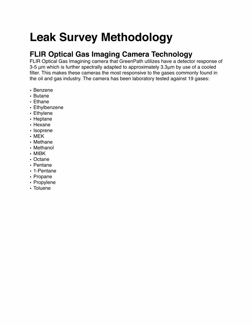
Leak Survey MethodologyFLIR Optical Gas Imaging Camera TechnologyFLIR Optical Gas Imagining camera that GreenPath utilizes have a detector response of 3-5 μm which is further spectrally adapted to approximately 3.3μm by use of a cooled filter. This makes these cameras the most responsive to the gases commonly found in the oil and gas industry. The camera has been laboratory tested against 19 gases:
Target ComponentsThe first step is determining which types of components will be targeted. The objective is to minimize the potential for leaks in the most practicable manner possible. This is done by focusing efforts on the components and service applications most likely to offer significant cost-effective control opportunities. Target components for inspection include:Compressor- Reciprocating & Centrifugal Valve Covers
Variable Volume Pocket
Governor
Cylinder head
Cylinder Bleed
Cylinder Body
Compressor Seals Packing Case Drain
Distance Piece Vent
Common Vent
Crank Case Vent
Engine Governor
Injector
Crank Case Vent
Valves (All types) Stem Packing
Diaphragm
Actuator Seal
Seal
Body
Connections Threaded
Flanged
Mechanical
Instrument Fitting
Open-Ended Line All
Storage Tanks All
Pump Seals All
PSV/PRV All
Regulators All
Pneumatic Instrumentation Controls All
Facility inspection ProcessAt every facility we inspect, we always go beyond the “lens” of the FLIR camera to source the origin of an emission. Many emission sources are located simply following the trial of clues with trained senses. These clues include odors, staining, ground depressions, audible traces, noticeable damage, building doors and windows propped open, bypassed or disconnected LEL detectors.
Our scanning methodology follows a general sequence of scanning each component from one end to the other. To ensure we detect all sources of fugitive emissions at each facility we inspect, we scan each targeted component from at least two separate angles with the FLIR camera firmly stabilized. This ensures the effectiveness of the FLIR camera and that the best possible video recording quality is obtained.
Video of detected fugitive emissions, are recorded for a minimum of 10 seconds directly to our specialized Our fugitive emission inspections follow a general methodology:
1.From an advantageous perspective, we scan all outdoor stacks, vents, tanks and flares and building vents. Emissions from these sources can be safety concerns and/or a symptom of other underlying issues such as passing PSV/PRVs, faulty separator dump valves and incorrect operation of equipment. This general broad scan gives us a sense of what we can anticipate further in the inspection and allows us to note any safety concerns. Emissions detected at this stage are further investigated with the intent to report the cause and not the symptom of the emission source.
2.Scanning the facility usually follows the flow of gas as it is moved from one production stage to another.
�
3.At each production stage an exterior scan of the building process envelope is performed. Each exterior component is scanned from a least two different angles and any emissions detected are recorded and reported.
4.After inspecting the outer envelope process components, we focus inspection efforts on target components contained within the boundaries of the building envelope. Again, each component is scanned from at least two different angles and all emissions detected are recorded and reported.
5.Once all outer and inner process envelopes are scanned, all piping and components that connect each process together are inspected.
Inlet Separa*on Compression Dehydra*on Sales
6.By the end of inspection tour, the entire facility located within the operating boundaries has been inspected.
During inspections, we vigilantly take the individual facility characteristics and circumstances into consideration and when required to do so, we adjust our detection methodology accordingly. Cause for change can include:
• Co-ordination with other workers on site• Extreme environmental conditions• Needs and availability of field operations• Unplanned equipment failures and shut-downs
Emission Quantification We utilize the most efficient and accurate tools to quantify detected emissions during our inspections. Primarily, quantification of sweet methane emissions involves the use of the Hi-Flow Sampler. The Hi-Flow Sampler is accurate (+/- 10%), intrinsically safe, efficient and cost effective.
Quantifying fugitive emissions allows personnel to understand the economic consequences of leaking and venting emissions thus enabling them to make educated repair and reduction decisions. Other methods of quantification that we employ are:
• Calibrated volume bag measurement• Vane anemometer• Positive displacement meter
Quantification Device CalibrationAs per CAPP BMP record keeping & measurement requirements, GreenPath quantification devices will be calibrated according to legislative, manufacturer’s, or other written specification or requirements confirm the accuracy and that the devices are operating correctly.
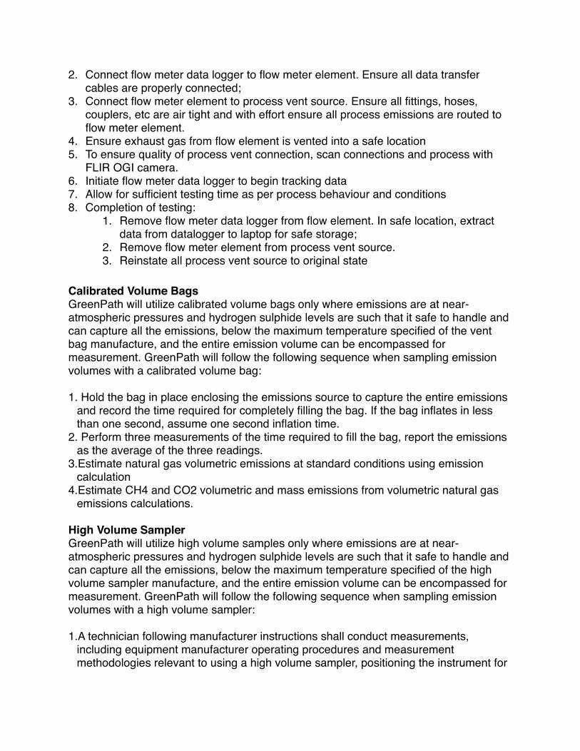
Postive Displacement Flow MetersGreenPath shall use measurement methods, maintenance practices and calibration methods prior to the first reporting year and in each subsequent reporting year using appropriate standards. Greenpath will follow the following sequence with sampling emission volumes with a calibrated flow meter:
1. In a safe location, connect flow meter data logger to laptop for setup. Ensure following data is entered for program into flow meter data logger:
2. Connect flow meter data logger to flow meter element. Ensure all data transfer cables are properly connected;
3. Connect flow meter element to process vent source. Ensure all fittings, hoses, couplers, etc are air tight and with effort ensure all process emissions are routed to flow meter element.
4. Ensure exhaust gas from flow element is vented into a safe location5. To ensure quality of process vent connection, scan connections and process with
FLIR OGI camera. 6. Initiate flow meter data logger to begin tracking data7. Allow for sufficient testing time as per process behaviour and conditions8. Completion of testing:
1. Remove flow meter data logger from flow element. In safe location, extract data from datalogger to laptop for safe storage;
2. Remove flow meter element from process vent source.3. Reinstate all process vent source to original state
Calibrated Volume BagsGreenPath will utilize calibrated volume bags only where emissions are at near-atmospheric pressures and hydrogen sulphide levels are such that it safe to handle and can capture all the emissions, below the maximum temperature specified of the vent bag manufacture, and the entire emission volume can be encompassed for measurement. GreenPath will follow the following sequence when sampling emission volumes with a calibrated volume bag:
1. Hold the bag in place enclosing the emissions source to capture the entire emissions and record the time required for completely filling the bag. If the bag inflates in less than one second, assume one second inflation time.
2. Perform three measurements of the time required to fill the bag, report the emissions as the average of the three readings.
3.Estimate natural gas volumetric emissions at standard conditions using emission calculation
4.Estimate CH4 and CO2 volumetric and mass emissions from volumetric natural gas emissions calculations.
High Volume SamplerGreenPath will utilize high volume samples only where emissions are at near-atmospheric pressures and hydrogen sulphide levels are such that it safe to handle and can capture all the emissions, below the maximum temperature specified of the high volume sampler manufacture, and the entire emission volume can be encompassed for measurement. GreenPath will follow the following sequence when sampling emission volumes with a high volume sampler:
1.A technician following manufacturer instructions shall conduct measurements, including equipment manufacturer operating procedures and measurement methodologies relevant to using a high volume sampler, positioning the instrument for
complete capture of the fugitive equipment leaks without creating back pressure on the source.
2.If the high volume sampler, along with all attachments available from the manufacturer is not able to capture all the emissions from the source then you shall use anti-static wraps or other aids to capture all emissions without violating operating requirements as provided in the instrument manufacturer’s manual.
3. Estimate CH4 and CO2 volumetric and mass emissions from volumetric natural gas emissions calculations.
4.Calibrate the instrument at 2.5 percent methane with 97.5 percent air and 100 percent CH4 by using calibrated gas samples and by following manufacturer’s instructions for calibration.
Emission TaggingDetected emission sources at each facility are tagged with chemical resistant tags to aid with repair, reduction and identification actions. Each tag provides:
• Unique serial # for tracking emission source• Detailed description of emission source • Quantified flow rate• Tracking for emission repairs and reduction attempts
Emission tags are attached as close as possible to the emission source. In the event that it is not feasible to attach directly to the source, the tag is placed as close as possible in a location that is visible to facility personnel. These tags should remain in place even after repairs have been made for the purpose of future tracking and facility inspections.
Emission Reporting & TrackingDetected emissions and associated data at each facility is recorded and transferred to GreenPath online accessible database directly. This online data was developed. to allow GreenPath to:
• View playback records of fugitive emission videos and pictures• Print facility reports in both CSV and PDF format• Track emissions by source, location and equipment for emissions reporting and
internal requirements• Track and manage repair opportunities• Show due diligence to regulatory authorities
Repair Verification Verification of repairs should be accomplished by third party the next facility inspections or at request of facility operators. Component repairs should be verified by means such as:
Infrared GasFindIR CameraThis is the most definitive solution but can result in false positive results when not used by trained personnel.
Bubble TestWe recommend a simple mixture of dish soap and water in a spray bottle. Based on our experience, this simple procedure outperforms many other expensive solutions.
Facility Inspection Frequency All facilities that have been flagged as priority targets should be inspected to ensure correct, up to date measurements of each facility are obtained for correct facility ranking and benchmarking.
Coordinating inspections before a turn-around or shut-down is encouraged. This allows personnel to take advantage of down time and budget appropriately for the required repairs. Also, an inspection should follow any major work carried out at facilities to ensure that the facility is “tight” and poses no HSE issues. We appreciate the opportunity to review our client’s current programs on routine and preventative maintenance of the facilities and equipment and any recent turn-around schedules.
Component Repair Costs and Mean Repair LifeA number of factors affect the total cost of repairing or replacing a leaking component. These include:
• Complexity of repair• The type and size of the component• Local contractor/maintenance staff• Amount of materials and auxiliary equipment requirements.
When possible, the actual cost of repair is obtained by the facility operator. In order to estimate the total value of repairing/replacing a leaking component, a mean life of repair must be calculated. The mean life of repair is the amount on time the repair will likely last. For each leak, the mean repair life is estimated based on the brand, configuration and class of the component, the type of component service (corrosive, heat, weathering, etc), level of usage and general maintenance procedures at the specific facility.