Page 1
Slide 1
© Eckhard A. Groll October 3, 2016
Analysis of Novel Compression Concepts for Heat Pumping, Air Conditioning and
Refrigeration Applications
Oklahoma State University Seminar Presentation
Dr.-Ing. Eckhard A. Groll
Reilly Professor of Mechanical Engineering
Director of the Office of Professional Practice
Purdue University
Ray W. Herrick Laboratories
West Lafayette, Indiana 47907, USA
Phone: 765-494-7429; Fax: 765-494-7427
E-mail: [email protected]
Page 2
Slide 2
© Eckhard A. Groll October 3, 2016
Contents
Introduction
Modeling of Compressors
Rotating Spool Compressor
S-RAM Compressor
Bowtie Compressor
Z-Compressor
Linear Compressor
Page 3
Slide 3
© Eckhard A. Groll October 3, 2016
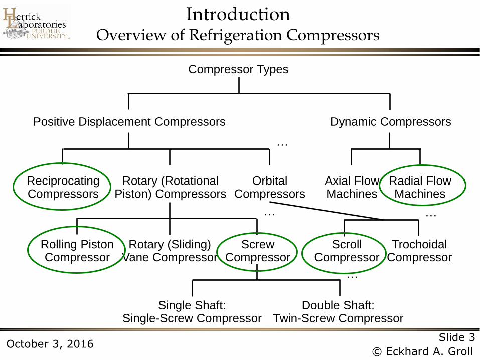
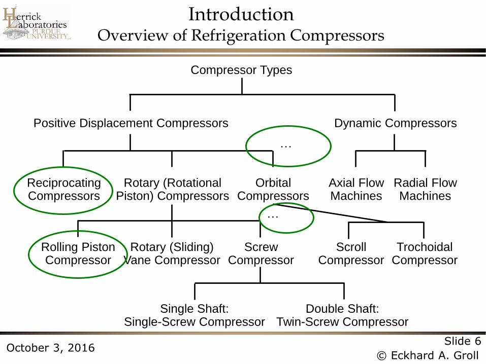
Introduction Overview of Refrigeration Compressors
Compressor Types
Positive Displacement Compressors Dynamic Compressors
Axial Flow Machines
Radial Flow Machines
Orbital Compressors
Rotary (Rotational Piston) Compressors
Reciprocating Compressors
Rotary (Sliding) Vane Compressor
Rolling Piston Compressor
Screw Compressor
Scroll Compressor
Trochoidal Compressor
Single Shaft: Single-Screw Compressor
Double Shaft: Twin-Screw Compressor
…
…
…
…
Page 4
Slide 4
© Eckhard A. Groll October 3, 2016
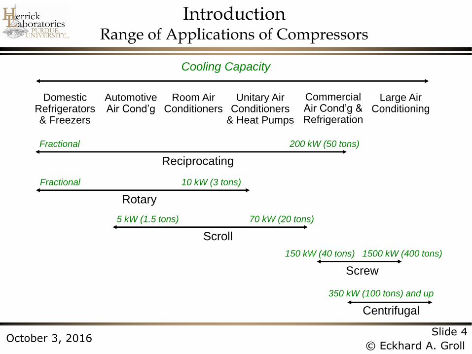
Introduction Range of Applications of Compressors
Domestic Refrigerators & Freezers
Automotive Air Cond’g
Room Air Conditioners
Unitary Air Conditioners
& Heat Pumps
Commercial Air Cond’g & Refrigeration
Large Air Conditioning
Cooling Capacity
Fractional 200 kW (50 tons)
Reciprocating
Fractional 10 kW (3 tons)
Rotary
5 kW (1.5 tons) 70 kW (20 tons)
Scroll
150 kW (40 tons) 1500 kW (400 tons)
Screw
350 kW (100 tons) and up
Centrifugal
Page 5
Slide 5
© Eckhard A. Groll October 3, 2016
Political and economic concerns
» Global warming
» Ozone depletion
» Increased competition
Technological advances
» New working fluids
» New design and manufacturing capabilities
» New applications
Introduction Motivation for New Compression Concepts
Page 6
Slide 6
© Eckhard A. Groll October 3, 2016
Introduction Overview of Refrigeration Compressors
Compressor Types
Positive Displacement Compressors Dynamic Compressors
Axial Flow Machines
Radial Flow Machines
Orbital Compressors
Rotary (Rotational Piston) Compressors
Reciprocating Compressors
Rotary (Sliding) Vane Compressor
Rolling Piston Compressor
Screw Compressor
Scroll Compressor
Trochoidal Compressor
Single Shaft: Single-Screw Compressor
Double Shaft: Twin-Screw Compressor
…
…
Page 7
Slide 7
© Eckhard A. Groll October 3, 2016
Contents
Introduction
Modeling of Compressors
Rotating Spool Compressor
S-RAM Compressor
Bowtie Compressor
Z-Compressor
Linear Compressor
Page 8
Slide 8
© Eckhard A. Groll October 3, 2016
Modeling of Compressors: Underlying Principles
Compressor modeling relies on many engineering
disciplines:
» Thermodynamics
– e.g.: Changes in refrigerant properties
» Fluid mechanics
– e.g.: Flow of refrigerant in chambers and flow passages
» Solid mechanics
– e.g.: Forces acting on valves and the resulting deformations
» Electrical engineering
– e.g.: Conversion of electrical energy to mechanical energy in a motor
» Chemical engineering
– e.g.: Unwanted decomposition of refrigerant and oil
Page 9
Slide 9
© Eckhard A. Groll October 3, 2016
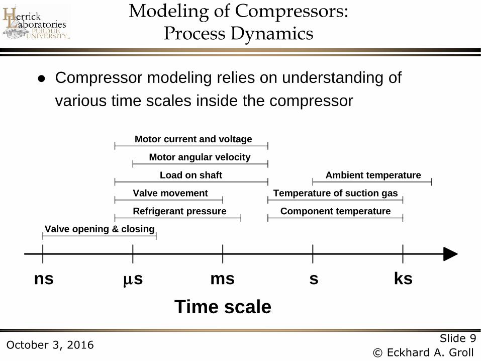
Modeling of Compressors: Process Dynamics
Compressor modeling relies on understanding of
various time scales inside the compressor
Refrigerant pressure
Valve movement
Load on shaft
Motor angular velocity
Motor current and voltage
Temperature of suction gas
Ambient temperature
Component temperature
sns ms s ks
Time scale
Valve opening & closing
Page 10
Slide 10
© Eckhard A. Groll October 3, 2016
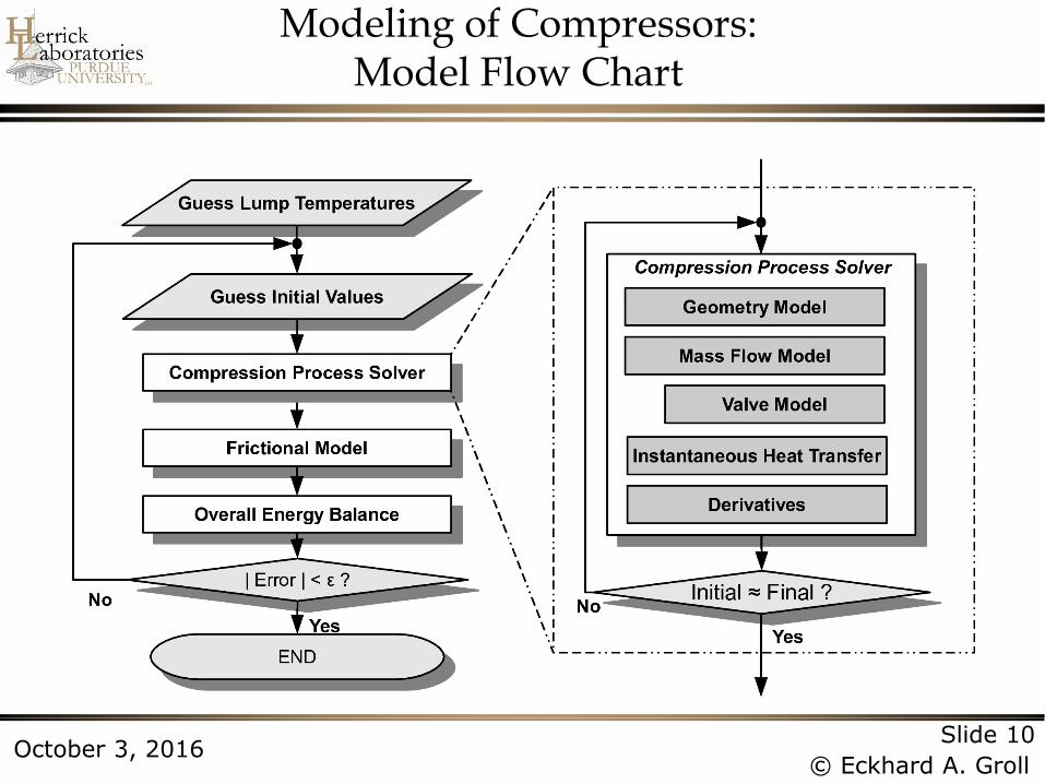
Modeling of Compressors: Model Flow Chart
Page 11
Slide 11
© Eckhard A. Groll October 3, 2016
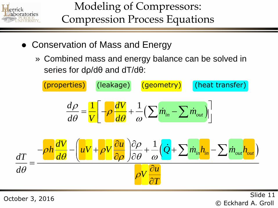
(properties) (geometry) (leakage) (heat transfer)
Conservation of Mass and Energy
» Combined mass and energy balance can be solved in
series for dρ/dθ and dT/dθ:
1
in in out out
dV uh uV V Q m h m h
ddT
udV
T
1 1
in out
d dVm m
d V d
Modeling of Compressors: Compression Process Equations
Page 12
Slide 12
© Eckhard A. Groll October 3, 2016
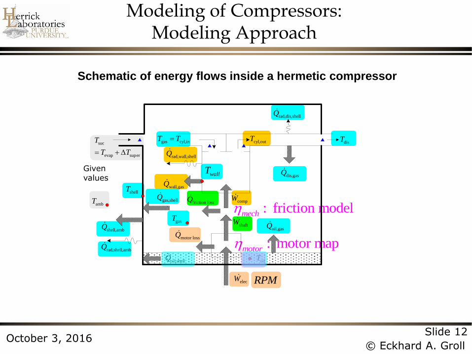
Schematic of energy flows inside a hermetic compressor
: friction modelmech
: motor mapmotor
RPM
Given values
ambT
gasT
shellT
wallT
motor lossQ
wall,gasQ
gas,shellQ
shell,ambQ
suc
evap super
T
T T
elecW
shaftW
compWfriction lossQ
gas cyl,inT TdisT
dis,gasQ
oilT
oil,gasQ
oil,shellQ
cyl,outT
rad,wall,shellQ
rad,shell,ambQ
rad,dis,shellQ
Modeling of Compressors: Modeling Approach
Page 13
Slide 13
© Eckhard A. Groll October 3, 2016
Contents
Introduction
Modeling of Compressors
Rotating Spool Compressor
S-RAM Compressor
Bowtie Compressor
Z-Compressor
Linear Compressor
Page 14
Slide 14
© Eckhard A. Groll October 3, 2016
• Introduced by Kemp et al. (2008, 2010)
• Performance data presented by Orosz et al. (2012)
• Model(s) presented by Bradshaw et al. (2013) and Bradshaw, C.R. (2013)
Motivation: Achieve competitive compressor performance at
significantly reduced manufacturing costs
Rotating Spool Compressor: Design
Page 15
Slide 15
© Eckhard A. Groll October 3, 2016
Rotating Spool Compressor: Design
Page 16
Slide 16
© Eckhard A. Groll October 3, 2016
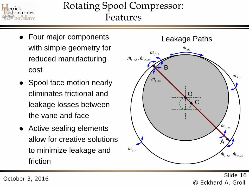
Rotating Spool Compressor: Features
Four major components
with simple geometry for
reduced manufacturing
cost
Spool face motion nearly
eliminates frictional and
leakage losses between
the vane and face
Active sealing elements
allow for creative solutions
to minimize leakage and
friction
Leakage Paths
Page 17
Slide 17
© Eckhard A. Groll October 3, 2016
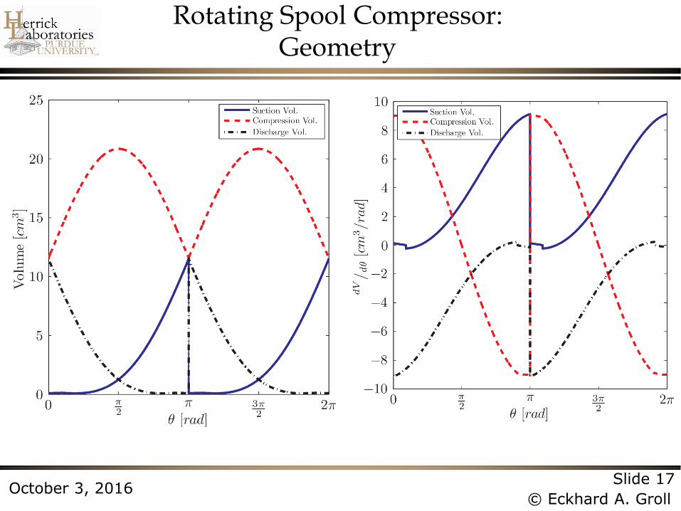
Rotating Spool Compressor: Geometry
Page 18
Slide 18
© Eckhard A. Groll October 3, 2016
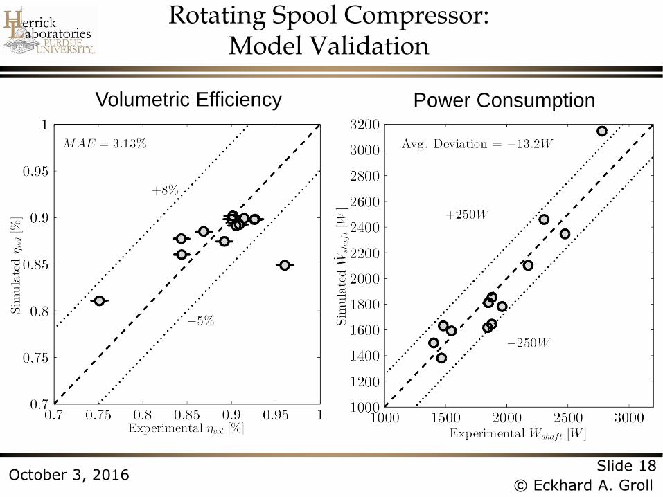
Rotating Spool Compressor: Model Validation
Power Consumption Volumetric Efficiency
Page 19
Slide 19
© Eckhard A. Groll October 3, 2016
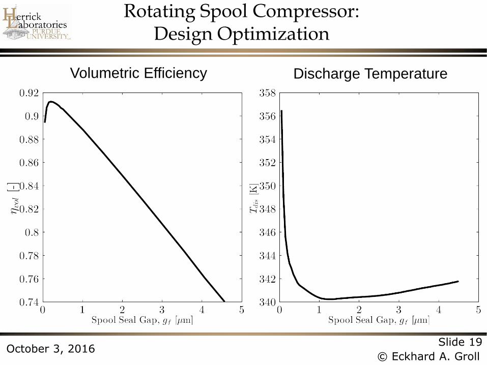
Rotating Spool Compressor: Design Optimization
Discharge Temperature Volumetric Efficiency
Page 20
Slide 20
© Eckhard A. Groll October 3, 2016
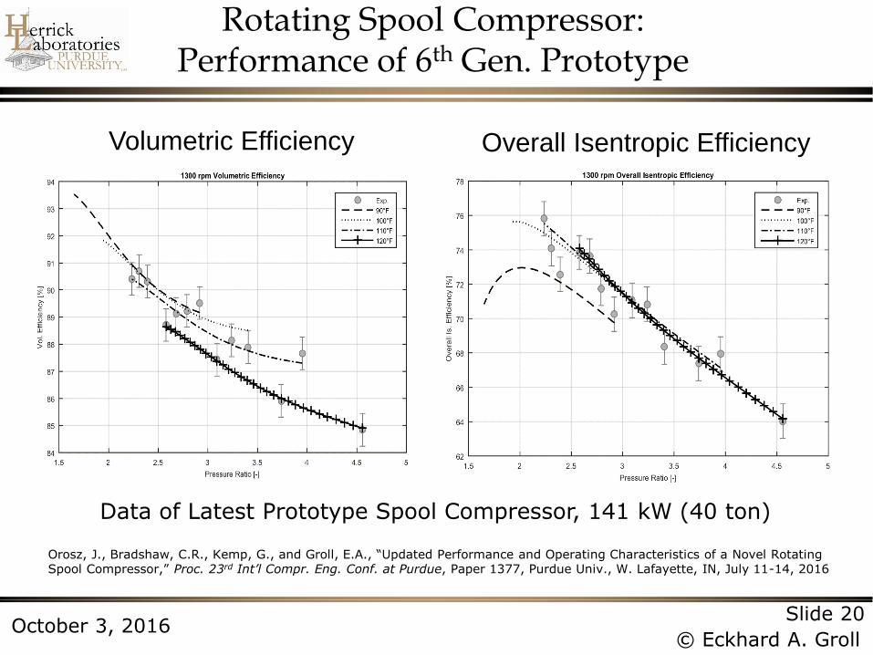
Rotating Spool Compressor: Performance of 6th Gen. Prototype
Overall Isentropic Efficiency Volumetric Efficiency
Data of Latest Prototype Spool Compressor, 141 kW (40 ton)
Orosz, J., Bradshaw, C.R., Kemp, G., and Groll, E.A., “Updated Performance and Operating Characteristics of a Novel Rotating Spool Compressor,” Proc. 23rd Int’l Compr. Eng. Conf. at Purdue, Paper 1377, Purdue Univ., W. Lafayette, IN, July 11-14, 2016
Page 21
Slide 21
© Eckhard A. Groll October 3, 2016
Rotating Spool Compressor: Summary
Latest generation prototype achieves competitive
volumetric and energy efficiencies
Manufacturing cost much lower than scroll
compressors
Size range comparable to reciprocating compressors
Commercialization interaction with multiple
compressor manufacturers
Concept shows good performance as an expander in
ORC applications
Page 22
Slide 22
© Eckhard A. Groll October 3, 2016
Contents
Introduction
Modeling of Compressors
Rotating Spool Compressor
S-RAM Compressor
Bowtie Compressor
Z-Compressor
Linear Compressor
Page 23
Slide 23
© Eckhard A. Groll October 3, 2016
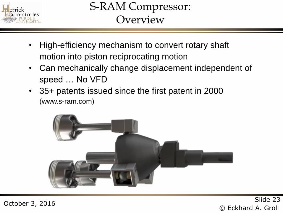
S-RAM Compressor: Overview
• High-efficiency mechanism to convert rotary shaft
motion into piston reciprocating motion
• Can mechanically change displacement independent of
speed … No VFD
• 35+ patents issued since the first patent in 2000 (www.s-ram.com)
Page 24
Slide 24
© Eckhard A. Groll October 3, 2016
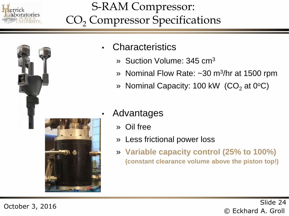
S-RAM Compressor: CO2 Compressor Specifications
• Characteristics
» Suction Volume: 345 cm3
» Nominal Flow Rate: ~30 m3/hr at 1500 rpm
» Nominal Capacity: 100 kW (CO2 at 0oC)
• Advantages
» Oil free
» Less frictional power loss
» Variable capacity control (25% to 100%) (constant clearance volume above the piston top!)
Page 25
Slide 25
© Eckhard A. Groll October 3, 2016
S-RAM Compressor: Kinematics Model
Piston Displacement/Velocity/Acceleration
Page 26
Slide 26
© Eckhard A. Groll October 3, 2016
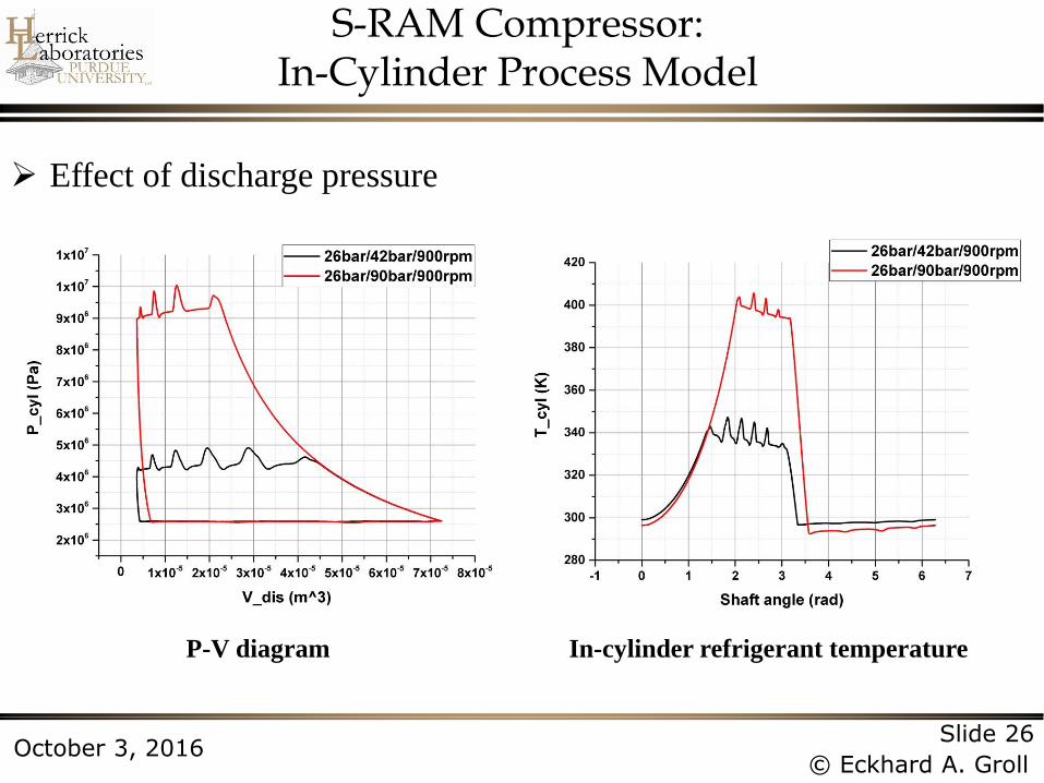
S-RAM Compressor: In-Cylinder Process Model
Effect of discharge pressure
P-V diagram In-cylinder refrigerant temperature
Page 27
Slide 27
© Eckhard A. Groll October 3, 2016
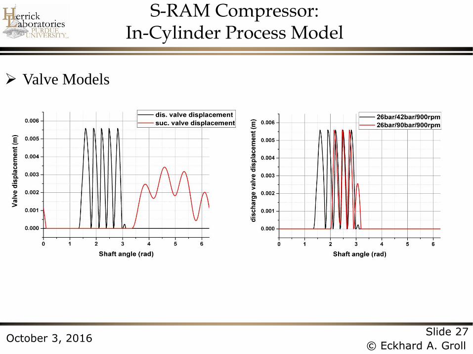
S-RAM Compressor: In-Cylinder Process Model
Valve Models
Page 28
Slide 28
© Eckhard A. Groll October 3, 2016
S-RAM Compressor: In-Cylinder Process Model
Effect of stroke-to-bore ratio
Instantaneous refrigerant leakage through clearance
between piston assembly and cylinder wall
Instantaneous heat transfer between
in-cylinder refrigerant and cylinder wall
Page 29
Slide 29
© Eckhard A. Groll October 3, 2016
S-RAM Compressor: Predicted Efficiencies
Effect of stroke-to-bore ratio
Volumetric Efficiency:
0
vol
suc
m
V Nn
Compressor
displacement
volume
Compressor
speed
Number of
cylinders
Yang, B., Kurtulus, O., and Groll, E.A., “An Integrated Model for an Oil Free Carbon Dioxide Compressor Using Sanderson-Rocker Arm Motion (S-RAM) Mechanism,” Proc. 23rd Int’l Compr. Eng. Conf. at Purdue, Paper 1336, Purdue Univ., W. Lafayette, IN, July 11-14, 2016
Page 30
Slide 30
© Eckhard A. Groll October 3, 2016
S-RAM Compressor: Summary
Oil-free compression provides large application range
Variable capacity control while keeping clearance
volume constant gives high performance at different
operating conditions
Competitive compressor performance at different
pressure ratios
Future Work:
» Frictional power loss analysis
» Global energy balance analysis
» Validation of model predictions
Page 31
Slide 31
© Eckhard A. Groll October 3, 2016
Contents
Introduction
Modeling of Compressors
Rotating Spool Compressor
S-RAM Compressor
Bowtie Compressor
Z-Compressor
Linear Compressor
Page 32
Slide 32
© Eckhard A. Groll October 3, 2016
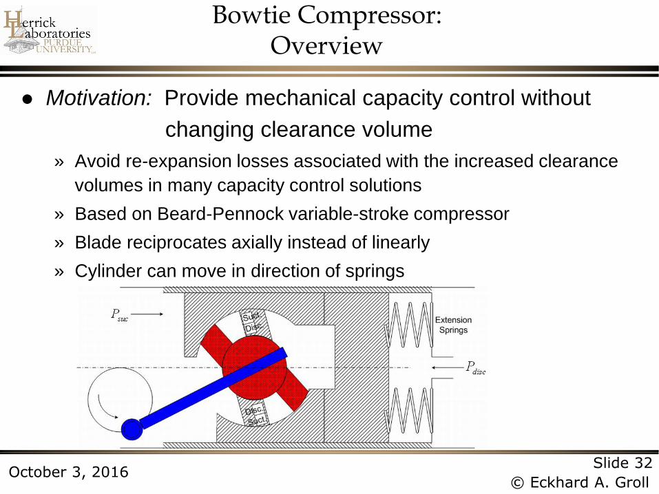
Bowtie Compressor: Overview
Motivation: Provide mechanical capacity control without
changing clearance volume
» Avoid re-expansion losses associated with the increased clearance
volumes in many capacity control solutions
» Based on Beard-Pennock variable-stroke compressor
» Blade reciprocates axially instead of linearly
» Cylinder can move in direction of springs
Page 33
Slide 33
© Eckhard A. Groll October 3, 2016
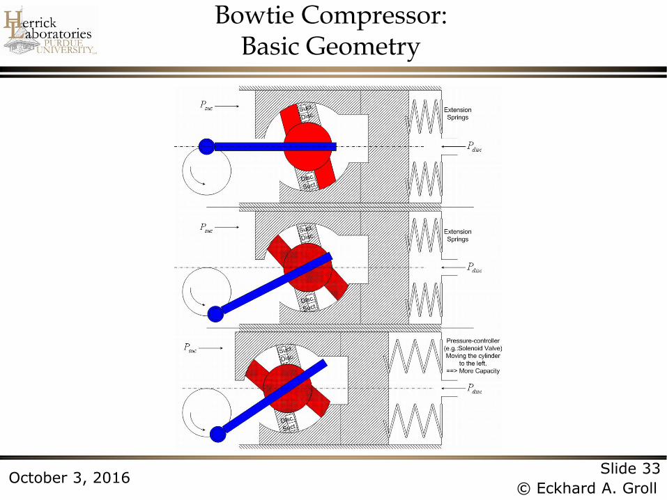
Bowtie Compressor: Basic Geometry
Page 34
Slide 34
© Eckhard A. Groll October 3, 2016
Bowtie Compressor: Prototype Design
Leakage passages:
» Through the radial
clearance
» Over the vane
» Between the side vane
and the journal shaft
» Between the journal
bearing and the journal
shaft
» Between the top vane
and the journal shaft
,011 leakm
,022 leakm ,044 leakm
,033 leakm
,055 leakm
Page 35
Slide 35
© Eckhard A. Groll October 3, 2016
Bowtie Compressor: Model Validation
-24 -22 -20 -18 -16 -14 -1210
12
14
16
18
20
22
Ma
ss F
low
Ra
te (
lbm
/hr)
Evaporating Temperature (oC)
Tcond
=43.3oC,Map
Tcond
=43.3oC,Model
Tcond
=48.9oC,Map
Tcond
=48.9oC,Model
Tcond
=54.4oC,Map
Tcond
=54.4oC,Model
-24 -22 -20 -18 -16 -14 -12
160
170
180
190
200
210
220
230
Po
we
r In
pu
t (W
)
Evaporating Temperature (oC)
Tcond
=43.4oC,Map
Tcond
=43.4oC,Model
Tcond
=48.9oC,Map
Tcond
=48.9oC,Model
Tcond
=54.4oC,Map
Tcond
=54.4oC,Model
Power Consumption Mass Flow Rate
Page 36
Slide 36
© Eckhard A. Groll October 3, 2016
0.0 0.5 1.0 1.5 2.0 2.5 3.0 3.5 4.0 4.5 5.0 5.5
50
52
54
56
58
60
62
Ove
rall
Ise
ntr
op
ic C
om
pre
sso
r E
ffic
ien
cy (
%)
Clearance (m)
Use model to optimize clearance dimensions and ratio of vane radius
to height
Friction
losses
dominate
0.2
5
0.5
0
0.7
5
1.0
0
1.2
5
1.5
0
1.7
5
2.0
0
2.2
5
2.5
0
2.7
5
1.470
1.475
1.480
1.485
1.490
1.495
1.500
1.505
1.510
1.515
1.520
Mass Flow Rate, Swept Angle = 25.05o
Mass Flow Rate, Swept Angle = 31.89o
o.s.c
, Swept Angle = 25.05o
o.s.c
, Swept Angle = 31.89o
Ratio of Vane Radius and Height
Co
mp
resso
r M
ass F
low
Ra
te (
g/s
ec)
59.0
59.2
59.4
59.6
59.8
60.0
60.2
60.4
60.6
60.8
61.0
Ove
rall Is
en
trop
ic C
om
pre
sso
r Effic
ien
cy (%
)
Leakage
losses
dominate
Maximum
performance
Bowtie Compressor: Design Optimization
Page 37
Slide 37
© Eckhard A. Groll October 3, 2016
Bowtie Compressor: Performance Results
Modeled results for compressor at 54.4ºC condensing,
-23.3ºC evaporating and 32.2ºC suction temperature:
0 50 100 150 200 250 300 350 4000
10
20
30
40
50
60
70
80
90
Mo
tor
Eff
icie
ncy (
%)
Shaft Power (W)
Tecumseh Recipro. Compressor Model (TP1390)Compressor Motor Map
3.0 3.5 4.0 4.5 5.00.6
0.8
1.0
1.2
1.4
1.6
Mass Flow Rate
o.s.c
Swept Volume (cm3)
Ma
ss F
low
Ra
te (
g/s
ec)
0
5
10
15
20
25
30
35
40
45
50
55
60
65
-52.0%
-42.8%
-31.4%
-17.5%
-20.6%
-14.8%-9.2%
Overa
ll Isentro
pic
Com
pre
ssor E
fficie
ncy(%
)
-4.3%
Page 38
Slide 38
© Eckhard A. Groll October 3, 2016
Bowtie Compressor: Summary
Overall isentropic efficiency only drops from
60 to 50% when suction volume is reduced from
4.70 cm3 to 3.04 cm3 (almost 50% decrease)
Change in overall isentropic efficiency could be
significantly less if appropriate electric motor is used
Feasible, “lower-cost” alternative to electronic variable
speed compressor for domestic refrigerator/freezer
Current interest by German Company in electronic
cabinet cooling using reversed Brayton cycle.
Page 39
Slide 39
© Eckhard A. Groll October 3, 2016
Contents
Introduction
Modeling of Compressors
Rotating Spool Compressor
S-RAM Compressor
Bowtie Compressor
Z-Compressor
Linear Compressor
Page 40
Slide 40
© Eckhard A. Groll October 3, 2016
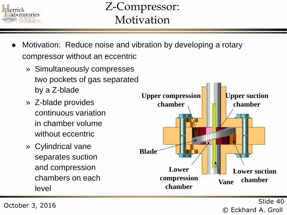
Z-Compressor: Motivation
Motivation: Reduce noise and vibration by developing a rotary
compressor without an eccentric
» Simultaneously compresses
two pockets of gas separated
by a Z-blade
» Z-blade provides
continuous variation
in chamber volume
without eccentric
» Cylindrical vane
separates suction
and compression
chambers on each
level
Lower suction
chamber
Upper suction
chamber
Upper compression
chamber
Lower
compression
chamber Vane
Blade
Page 41
Slide 41
© Eckhard A. Groll October 3, 2016
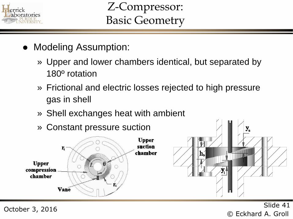
Z-Compressor: Basic Geometry
Modeling Assumption:
» Upper and lower chambers identical, but separated by
180º rotation
» Frictional and electric losses rejected to high pressure
gas in shell
» Shell exchanges heat with ambient
» Constant pressure suction
Page 42
Slide 42
© Eckhard A. Groll October 3, 2016
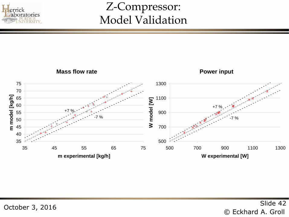
Z-Compressor: Model Validation
Mass flow rate
35
40
45
50
55
60
65
70
75
35 45 55 65 75
m experimental [kg/h]
m m
od
el
[kg
/h]
+7 %
-7 %
Power input
500
700
900
1100
1300
500 700 900 1100 1300
W experimental [W]W
mo
del
[W]
+7 %
-7 %
Page 43
Slide 43
© Eckhard A. Groll October 3, 2016
Leakage losses
0
1
2
3
4
5
6
0.20 0.30 0.40 0.50 0.60
(h/D)
mL [
kg
/h]
Paths L6-L9 Paths L4-L5
Z-Compressor: Performance Results
Lower volumetric efficiency than currently available rolling
piston compressors due to increased leakage paths
» Between suction and compression chambers on same level
» Between levels
» Between chambers and shell
Page 44
Slide 44
© Eckhard A. Groll October 3, 2016
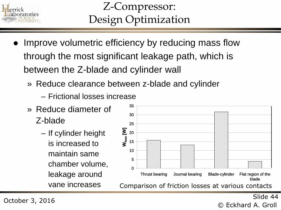
Z-Compressor: Design Optimization
Improve volumetric efficiency by reducing mass flow
through the most significant leakage path, which is
between the Z-blade and cylinder wall
» Reduce clearance between z-blade and cylinder
– Frictional losses increase
» Reduce diameter of
Z-blade
– If cylinder height
is increased to
maintain same
chamber volume,
leakage around
vane increases Comparison of friction losses at various contacts
Average frictional losses
0
5
10
15
20
25
30
35
Thrust bearing Journal bearing Blade-cylinder Flat region of the
blade
Contact
Wlo
ss [
W]
Average frictional losses
0
5
10
15
20
25
30
35
Thrust bearing Journal bearing Blade-cylinder Flat region of the
blade
Contact
Wlo
ss [
W]
Page 45
Slide 45
© Eckhard A. Groll October 3, 2016
Z-Compressor: Design Optimization, cont’d
Volumetric efficiency
Reference
Piston ring
0.800
0.825
0.850
0.875
0.900
0.925
0.950
15.0 17.5 20.0 22.5 25.0 27.5 30.0
Blade-cylinder clearance [m]
v
Overall isentropic efficiency
Reference
Piston ring
0.550
0.575
0.600
0.625
0.650
15.0 17.5 20.0 22.5 25.0 27.5 30.0
Blade-cylinder clearance [m]
s
Impact of blade-cylinder clearance change on compressor efficiencies
Page 46
Slide 46
© Eckhard A. Groll October 3, 2016
Z-Compressor: Summary
Compared to current rotary compressors:
» Lower noise and vibration
» But also, lower volumetric efficiency
Dimensions can be optimized to balance leakage and
friction losses for maximum isentropic efficiency
Feasible alternative to rolling piston compressor
for room and small unitary air conditioners,
but “higher” manufacturing costs
Current interest by Canadian company for small-scale
air compression application
Page 47
Slide 47
© Eckhard A. Groll October 3, 2016
Contents
Introduction
Modeling of Compressors
Rotating Spool Compressor
S-RAM Compressor
Bowtie Compressor
Z-Compressor
Linear Compressor
Page 48
Slide 48
© Eckhard A. Groll October 3, 2016
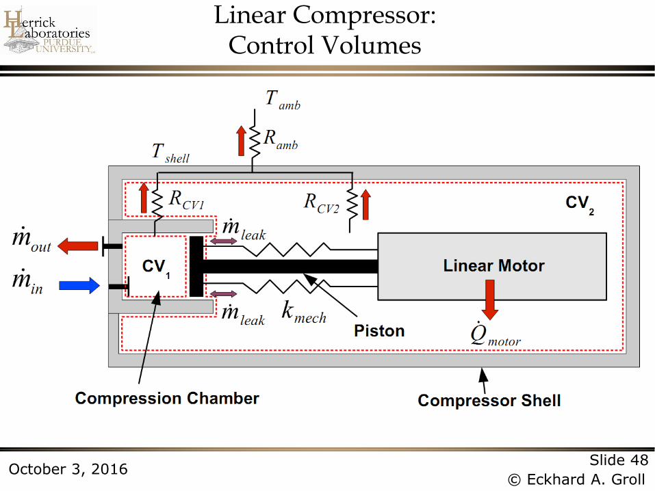
Linear Compressor: Control Volumes
Page 49
Slide 49
© Eckhard A. Groll October 3, 2016
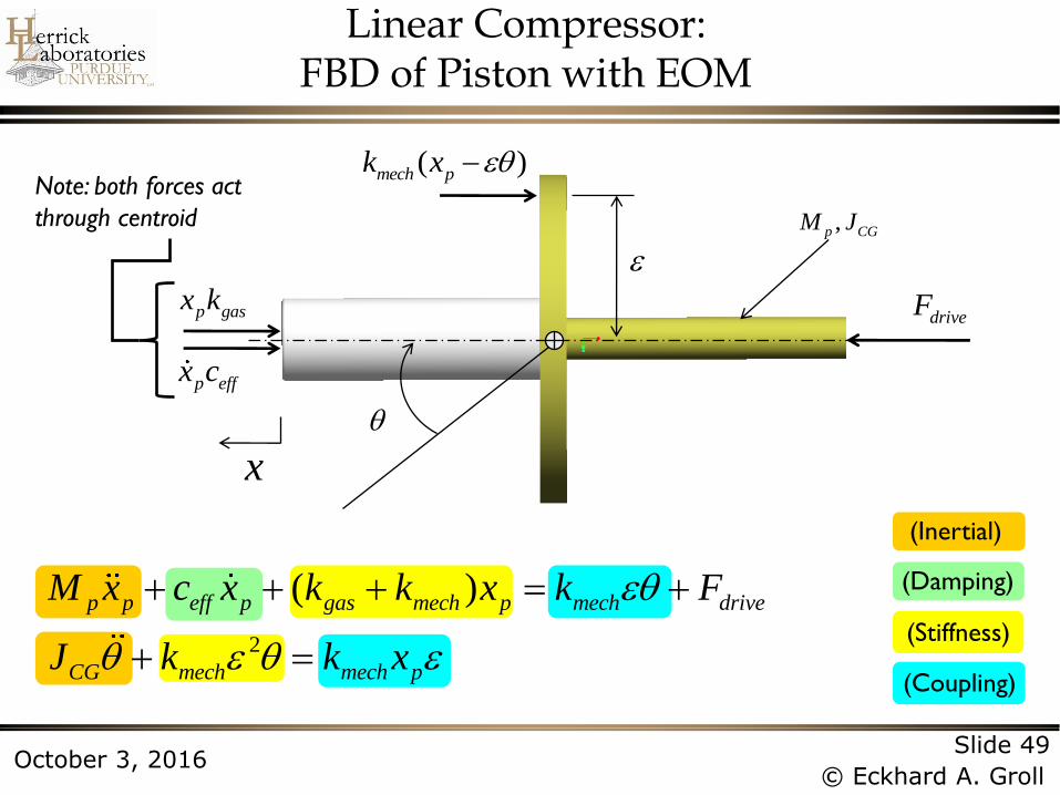
Linear Compressor: FBD of Piston with EOM
p gasx k
p effx c
( )mech pk x
,p CGM J
x
driveF
Note: both forces act
through centroid
(Coupling)
(Stiffness)
(Damping)
(Inertial)
2
( )p p eff p gas mech p mech drive
CG mech mech p
M x c x k k x k F
J k k x
Page 50
Slide 50
© Eckhard A. Groll October 3, 2016
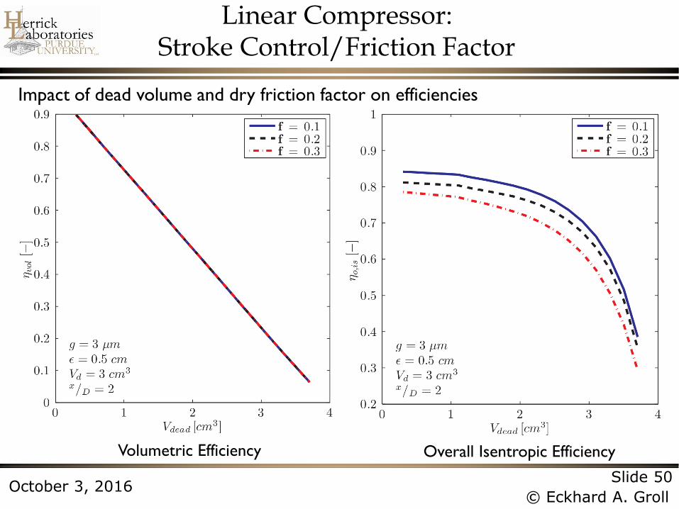
Linear Compressor: Stroke Control/Friction Factor
Impact of dead volume and dry friction factor on efficiencies
Volumetric Efficiency Overall Isentropic Efficiency
Page 51
Slide 51
© Eckhard A. Groll October 3, 2016
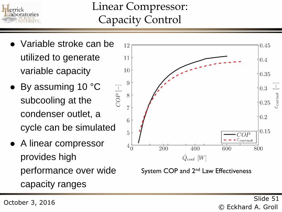
Linear Compressor: Capacity Control
Variable stroke can be
utilized to generate
variable capacity
By assuming 10 °C
subcooling at the
condenser outlet, a
cycle can be simulated
A linear compressor
provides high
performance over wide
capacity ranges
System COP and 2nd Law Effectiveness
Page 52
Slide 52
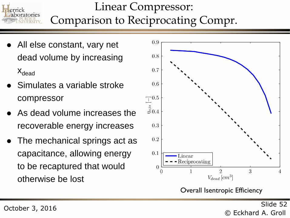
© Eckhard A. Groll October 3, 2016
All else constant, vary net
dead volume by increasing
xdead
Simulates a variable stroke
compressor
As dead volume increases the
recoverable energy increases
The mechanical springs act as
capacitance, allowing energy
to be recaptured that would
otherwise be lost
Overall Isentropic Efficiency
Linear Compressor: Comparison to Reciprocating Compr.
Page 53
Slide 53
© Eckhard A. Groll October 3, 2016
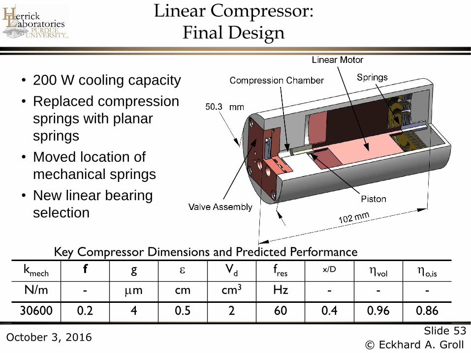
kmech f g Vd fres x/D vol o,is
N/m - m cm cm3 Hz - - -
30600 0.2 4 0.5 2 60 0.4 0.96 0.86
Key Compressor Dimensions and Predicted Performance
• 200 W cooling capacity
• Replaced compression
springs with planar
springs
• Moved location of
mechanical springs
• New linear bearing
selection
Linear Compressor: Final Design
Page 54
Slide 54
© Eckhard A. Groll October 3, 2016
Linear Compressor: Summary
Linear compressors are the highest performing
compressors on the market
Only two commercial products available
» Embraco and LG
» Both are for refrigerator-freezer application
Research interest focuses on scaling to larger
capacities
Page 55
Slide 55
© Eckhard A. Groll October 3, 2016
Thank you!