Analysis of the Effectiveness of Grid Codes for Offshore Wind Farms Connected to Onshore Grid via VSC-Based HVDC Moritz Mittelstaedt, Andreas Roehder,.Hendrik Natemeyer, Prof. Dr.-Ing. A. Schnettler Institute for High Voltage Technology RWTH Aachen University Conference of the Wind Power Engineering Community
Transcript
Moritz Mittelstaedt, VDI – COWEC in Berlin 2013
Analysis of the Effectiveness of Grid Codes for
Offshore Wind Farms Connected to Onshore Grid via
VSC-Based HVDC
Moritz Mittelstaedt,
Andreas Roehder,.Hendrik Natemeyer, Prof. Dr.-Ing. A. Schnettler
Institute for High Voltage Technology
RWTH Aachen University
Conference of the Wind Power Engineering
Community
Moritz Mittelstaedt, VDI – COWEC in Berlin 2013 2
Content
• Motivation and objectives
• Overview of relevant Grid Codes
• Model of an Offshore wind farm connected via VSC-HVDC
• Exemplary results from the stationary analysis
• Dynamic wind farm analysis under different fault cases
• Conclusion
Moritz Mittelstaedt, VDI – COWEC in Berlin 2013
Motivation
• High share of offshore wind power (>20 GW targeted
for 2020 in German North Sea)
• Especially distant large Wind Farms are connected to
Onshore-Grid via VSC-HVDC
3
• Guarantee for a reliable, but also efficient energy supply
• High Wind Farm requirements, based on the demands in
Onshore-Grid, applied to Offshore Wind Farms
• Unknown effectiveness of the Grid Codes, especially in
case of Offshore Wind Farms connected via VSC-HVDC
Source: TenneT GmbH
Source: UK Offshore Wind Report 2012
Moritz Mittelstaedt, VDI – COWEC in Berlin 2013
Central objectives
Steady-State and fault behaviour investigation of a representative Wind Farm
including a VSC-HVDC Model
Presentation of the main studies on the effectiveness and possible simplifications of
legal Grid Codes and requirements
Motivation to discuss a possible modification of existing Grid Codes
Who is responsible for System Services - Grid Operator or Wind Farm Operator?
4
Moritz Mittelstaedt, VDI – COWEC in Berlin 2013
Content
• Motivation and objectives
• Overview of relevant Grid Codes
• Model of an Offshore wind farm connected via VSC-HVDC
• Exemplary results from the stationary analysis
• Dynamic wind farm analysis under different fault cases
• Conclusion
5
Moritz Mittelstaedt, VDI – COWEC in Berlin 2013
Overview of relevant Grid Codes Grid Codes in Europe at a glance
Legal Framework
• Germany
German Ordinance on System Services by
Wind Energy Plants (SDLWindV),
Transmission Code 2007
• Spain
Operation Procedures P.O.12.1-3
• Denmark
Technical Regulation 3.2.5
• Great Britain
The Grid Code Issue 5, Revision 3
(incl. Offshore part)
Contents
• Classification of Wind Energy Units (WEU) regarding their size and connected voltage-grid level
• Requirements for the WEU in steady-state regarding e.g. Active/Reactive Power Supply
• Conditions for a disconnection from the Grid during faults
• Dynamic System Services during faults
Purpose
Necessary Flexibility for Grid Operators
Avoiding cascading active power loss
Fast and safe Return to stable Operation Point
6
Moritz Mittelstaedt, VDI – COWEC in Berlin 2013
Overview of relevant Grid Codes Requirements for German Offshore-WF
• Transmission Code 2007 / SDLWindV
• Guideline of a PQ-Diagram for the Operating Points
• Voltage- and Frequency-Control
• LVRT-Capability, WEU have to stay connected to the Grid during faults and
accomplish a contribution for system stability
• Control of reactive current injection by the WEU in relation to significant voltage
deviation
• No specific requirements or exceptions for Offshore-WEU
• Grid Codes of the operators for a seaside connection
• Similar to requirements for the Onshore WEU
• Exception is only a different reactive current supply during faults
7
Moritz Mittelstaedt, VDI – COWEC in Berlin 2013
Overview of relevant Grid Codes PQ-Diagram for the WEU-Operating Points
• The PQ-Diagram defines the
minimum obtainable Operation Area
• Three variations of PQ-Diagrams
can be forced by the Grid Operator
• PQ-Diagram depends on Grid
Voltage
• Depending on the Grid situation the
Grid Operator can order to operate
at specific points
• Onshore: Necessary flexibility to
react on deviations in the grid
8
Moritz Mittelstaedt, VDI – COWEC in Berlin 2013
Overview of relevant Grid Codes Control of reactive current supply
• In case of a voltage deviation the WEU must
back up the voltage by adjusting the reactive
current 𝐼𝐵
• reactive current deviation (∆𝐼𝐵) must be
proportional to the relevant deviation, defined by
the factor k
• For 3-pole faults e.g., WEU must be able to feed
in a reactive current of min. 100% of the rated
current
• active current 𝐼𝑊 can be reduced to obtain an
increased reactive current
• additional time progressing requirements Source: System Service Ordinance SDLWindV
9
Moritz Mittelstaedt, VDI – COWEC in Berlin 2013
Content
• Motivation and objectives
• Overview of relevant Grid Codes
• Model of an Offshore wind farm connected via VSC-HVDC
• Exemplary results from the stationary analysis
• Dynamic wind farm analysis under different fault cases
• Conclusion
10
Moritz Mittelstaedt, VDI – COWEC in Berlin 2013
Model of an Offshore wind farm DFIG Model
Generic Model of doubly-fed induction generator
(DFIG)
• Representation of the mechanical behaviour as a
oscillating Two-Mass-Model
• Implemented pitch control, Power-Frequency
Control, Protection Systems e.g. Overvoltage-
Protection, Crowbar-Protection
• LVRT-Capability
• In model 50 Wind Turbines of 6 MW in 10 rows are
applied
• Embedding in a 33 kV-Offshore-Grid
Generator
Crowbars Inverter
Chopper DC-Circuit with
capacitor
Rectifier
Filter
Turbine
Source: Perdana, Dissertation
Chalmers Universitiy of Technology
33/0.69 kV
Transformer
6,7 MVA
11
Moritz Mittelstaedt, VDI – COWEC in Berlin 2013
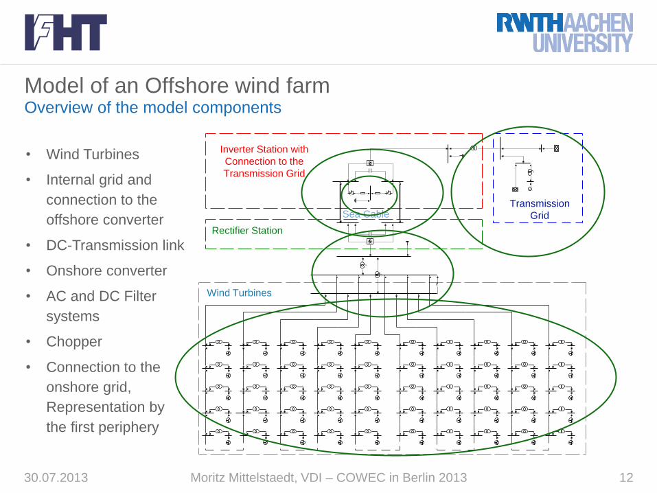
Model of an Offshore wind farm Overview of the model components
30.07.2013 12
Übertragungsnetz mit GKW
Gleichrichterstation
Wechselrichterstation und Anschluss an das
Übertragungsnetz
Seekabel
GKW
Windkraftanlagen
0
G~
0
0
1
1
Transmission
Grid
Inverter Station with
Connection to the
Transmission Grid
Rectifier Station
Wind Turbines
• Wind Turbines
• Internal grid and
connection to the
offshore converter
• DC-Transmission link
• Onshore converter
• AC and DC Filter
systems
• Chopper
• Connection to the
onshore grid,
Representation by
the first periphery
Sea Cable
Moritz Mittelstaedt, VDI – COWEC in Berlin 2013
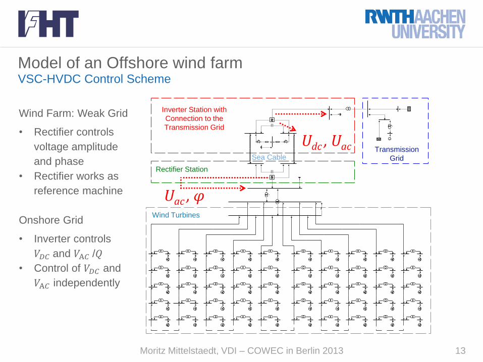
Model of an Offshore wind farm VSC-HVDC Control Scheme
Übertragungsnetz mit GKW
Gleichrichterstation
Wechselrichterstation und Anschluss an das
Übertragungsnetz
Seekabel
GKW
Windkraftanlagen
0
G~
0
0
1
1
Transmission
Grid
Inverter Station with
Connection to the
Transmission Grid
Sea Cable
Rectifier Station
Wind Turbines
Uac , φ
Udc , Uac
Wind Farm: Weak Grid
• Rectifier controls
voltage amplitude
and phase
• Rectifier works as
reference machine
Onshore Grid
• Inverter controls
𝑉𝐷𝐶 and 𝑉A𝐶 /𝑄
• Control of 𝑉𝐷𝐶 and
𝑉A𝐶 independently
13
Moritz Mittelstaedt, VDI – COWEC in Berlin 2013
Model of an Offshore wind farm Reactive Power Control
Realised Reactive Power Controls:
• Fix voltage or power factor control
by every WEU at local bus
(A power factor of cos(φ)=1 leads to
an infeed of Q=0 MVAr at the 33kV
Bus)
• Fix voltage or power factor control
by every row at the Central Wind
Farm Busbar
• Reactive Power Supply depending
on the Active Power Operation Point
of every WEU to minimize internal
Wind Farm losses
Übertragungsnetz mit GKW
Gleichrichterstation
Wechselrichterstation und Anschluss an das
Übertragungsnetz
Seekabel
GKW
Windkraftanlagen
0
G~
0
0
1
1
Fix cos(φ)
or Vbus
Fix cos(φ)
or Vbusbar
Minimize
PLosses
14
Moritz Mittelstaedt, VDI – COWEC in Berlin 2013
Content
• Motivation and objectives
• Overview of relevant Grid Codes
• Model of an Offshore wind farm connected via VSC-HVDC
• Exemplary results from the stationary analysis
• Dynamic wind farm analysis under different fault cases
• Conclusion
15
Moritz Mittelstaedt, VDI – COWEC in Berlin 2013
Stationary Analysis Selected control schemes
• Different control schemes
disencumber the converter
or the WEU electively
• Due to the VSC-HVDC the
wind farm is totally
decoupled from the
Onshore grid regarding
Reactive Power demand
• No impacts of voltage or
load variations on the Wind
Farm, contrary to the
operation in Ohnshore grid,
occur
-1,2
-1
-0,8
-0,6
-0,4
-0,2
0
-0,6 -0,4 -0,2 0 0,2 0,4 0,6
Reactive Power Q [p.u.]
Operation Points of the Converter
0,00
0,20
0,40
0,60
0,80
1,00
1,20
-0,50 -0,30 -0,10 0,10 0,30 0,50
underexcited - Reactive Power Q [p.u.] - overexcited
Operation Points of the WEU
1) x Q=0 LB
2) ■ Q=0 WF BB
16
Moritz Mittelstaedt, VDI – COWEC in Berlin 2013
Stationary Analysis Optimal Operation Points
• Dispersion of the given Active
Power infeed P inside between
the units ±5%
• Optimal power flow for minimum
Losses in the Offshore wind farm
• Investigation for (n-0) as well as
for any possible combination of
1-3 Wind Energy Units outages
• More than 99% of all
constellations are within a range
of -0,1 p.u. to 0,2 p.u.
Possible downsized minimum
reactive power supply range?
-0,1 p.u. < Q < 0,2 p.u. Operation Points of the WEUs
○ (n-0)
▽ (n-1)
△ (n-2)
x (n-3)
17
Moritz Mittelstaedt, VDI – COWEC in Berlin 2013
Content
• Motivation and objectives
• Overview of relevant Grid Codes
• Model of an Offshore wind farm connected via VSC-HVDC
• Exemplary results from the stationary analysis
• Dynamic wind farm analysis under different fault cases
• Conclusion
18
Moritz Mittelstaedt, VDI – COWEC in Berlin 2013
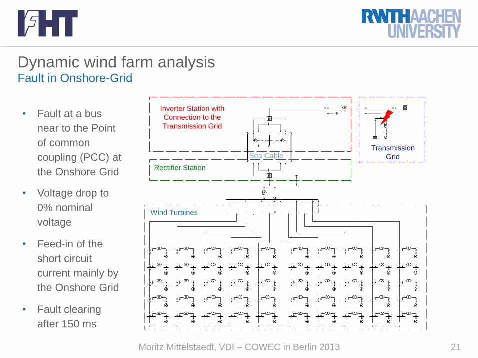
Dynamic wind farm analysis Fault in Offshore wind farm