Zeszyty Naukowe Akademii Morskiej w Szczecinie 41 (113) 9 Scientific Journals Zeszyty Naukowe of the Maritime University of Szczecin Akademii Morskiej w Szczecinie 2015, 41 (113), 9–16 ISSN 1733-8670 (Printed) ISSN 2392-0378 (Online) Analysis of tribological processes occuring in precision pairs based on example of fuel injection pumps of marine diesel engines Artur Bejger, Jan Drzewieniecki Maritime University of Szczecin, Department of Condition Monitoring & Maintenance of Machinery 70-205 Szczecin, ul. Podgórna 51/53, e-mail: {a.bejger; j.drzewieniecki}@am.szczecin.pl Key words: fuel injection pump, hydraulic precision pair, tribological processes, abrasive wear, erosion wear, cavitations Abstract This article draws attention to the problems of maintaining fuel injection pumps of marine diesel engines in the conditions of use of residual fuels whose quality is steadily deteriorating, and also burned under engine’s reduced load and in situations where the international rules require a temporary change over into distillate fuels. The analysis of tribological processes occurring in hydraulic precision pairs of fuel injection pump such as barrel-plunger was presented and the types of occurring wears were discussed based on author’s own operational experience. There was pointed out the need for additional methods of verification / evaluation of technical condition using of technical diagnostic methods. Introduction Introduction by the International Maritime Or- ganization (IMO) and the ratification by the associ- ated countries, the rules relating to the control of emissions in special areas called Emission Control Areas (ECA) through changes in the International Convention for the Prevention of Pollution from ships: MARPOL – Annex VI, not only raised the operating costs or forced to ship owners / managers to comply with the provisions of the Convention, but above all had an impact on the operation of ships. It necessitated the use of fuel oils with low sulfur content called low-sulfur fuels, and in many cases, has ruled out the use of residual fuel to distillate fuels [1, 2]. On the other hand, the global economic crisis and the continued rise in fuel prices have forced ship managers to seek ways to drastically reduce operating costs primarily related to fuel oil con- sumption, which constitutes nearly 75% of the costs of the ship’s operation. Nowadays, this is achieved by reducing the actual ship’s speed to the most economical speed or to so. very or extreme slow steaming, which however, under the reduced en- gine’s load conditions may lead to operational problems such as the increased wear of the tribological pairs and their components in the fuel system or in TPC assembly: piston – rings – cylin- der liner [3]. In addition, due to the steadily deteriorating quality of fuel oils and catalytic additives (Cat- fines) used in the refining processes of crude oil, the problem of the deterioration of working condi- tions in precision pairs, according to the literature [4] and the author’s own experience, it has become significant with respect to therefore accelerated wear occurring in the fuel injection pumps and then following operational problems especially in the case of main engines. Construction, design and working principles of fuel injection pump Fuel injection pumps (FIP) are one of the main components of marine diesel engine, and have a significant impact on its performance and reliabil- ity. Design and construction determine the amount of fuel injected and the injection time. There are two types of fuel injection pumps in marine construction of diesel engines with difference in method of controlling fuel quantity.
Transcript
Zeszyty Naukowe Akademii Morskiej w Szczecinie 41 (113) 9
Scientific Journals Zeszyty Naukowe of the Maritime University of Szczecin Akademii Morskiej w Szczecinie
Analysis of tribological processes occuring in precision pairs based on example of fuel injection pumps of marine diesel engines
Artur Bejger, Jan Drzewieniecki Maritime University of Szczecin, Department of Condition Monitoring & Maintenance of Machinery 70-205 Szczecin, ul. Podgórna 51/53, e-mail: {a.bejger; j.drzewieniecki}@am.szczecin.pl
Abstract This article draws attention to the problems of maintaining fuel injection pumps of marine diesel engines in the conditions of use of residual fuels whose quality is steadily deteriorating, and also burned under engine’s reduced load and in situations where the international rules require a temporary change over into distillate fuels. The analysis of tribological processes occurring in hydraulic precision pairs of fuel injection pump such as barrel-plunger was presented and the types of occurring wears were discussed based on author’s own operational experience. There was pointed out the need for additional methods of verification / evaluation of technical condition using of technical diagnostic methods.
Introduction
Introduction by the International Maritime Or-ganization (IMO) and the ratification by the associ-ated countries, the rules relating to the control of emissions in special areas called Emission Control Areas (ECA) through changes in the International Convention for the Prevention of Pollution from ships: MARPOL – Annex VI, not only raised the operating costs or forced to ship owners / managers to comply with the provisions of the Convention, but above all had an impact on the operation of ships. It necessitated the use of fuel oils with low sulfur content called low-sulfur fuels, and in many cases, has ruled out the use of residual fuel to distillate fuels [1, 2].
On the other hand, the global economic crisis and the continued rise in fuel prices have forced ship managers to seek ways to drastically reduce operating costs primarily related to fuel oil con-sumption, which constitutes nearly 75% of the costs of the ship’s operation. Nowadays, this is achieved by reducing the actual ship’s speed to the most economical speed or to so. very or extreme slow steaming, which however, under the reduced en-gine’s load conditions may lead to operational
problems such as the increased wear of the tribological pairs and their components in the fuel system or in TPC assembly: piston – rings – cylin-der liner [3].
In addition, due to the steadily deteriorating quality of fuel oils and catalytic additives (Cat-fines) used in the refining processes of crude oil, the problem of the deterioration of working condi-tions in precision pairs, according to the literature [4] and the author’s own experience, it has become significant with respect to therefore accelerated wear occurring in the fuel injection pumps and then following operational problems especially in the case of main engines.
Construction, design and working principles of fuel injection pump
Fuel injection pumps (FIP) are one of the main components of marine diesel engine, and have a significant impact on its performance and reliabil-ity. Design and construction determine the amount of fuel injected and the injection time.
There are two types of fuel injection pumps in marine construction of diesel engines with difference in method of controlling fuel quantity.
Artur Bejger, Jan Drzewieniecki
10 Scientific Journals of the Maritime University of Szczecin 41 (113)
The first method uses suction and spill valves operated by push rod and the second precision pair: barrel and helical plunger [5, 6].
The first group of pumps is applicable only in Wartsila (former SULZER) 2-stroke large power engines and applies to RTA engines, which are gradually replaced by electronically controlled RT-Flex engines not equipped with fuel injection pumps but with common piping called Common Rail. They occupy a small percentage of the market when it comes to engines installed on ships and in maritime sector or considering their application in shore power plants.
The second group of pumps is commonly used in two-stroke and four-stroke engines of all en-gine’s manufacturers, both high and low power, in design as individual for each cylinder or complex pumps. The introduction of electronically con-trolled engines by MAN B & W Diesel & Turbine didn’t change the approach to the design of the injection system by leaving fuel injection pumps but changing the way of control from conventional with use of camshaft into cam less system with electronic – hydraulic valves.
Both FIP constructions allow to adjust fuel oil feed rate and to change the end of injection. But the second type of pumps with application of VIT (Variable Injection Timing), allow also changing the beginning of injection, which means advancing or retarding the injection timing. It causes changes in the height of the barrel and thus changing the position of the spill ports against the plunger result-ing in varying the beginning of injection. This solution provides measurable benefits in terms of fuel economy at low engine loads and in case of use of fuel oils with different properties [5, 6, 7].
Accordingly to the above, in this article, the au-thors have presented problems of wear in FIP on the example of helical fuel pumps equipped with precision pair of barrel and plunger.
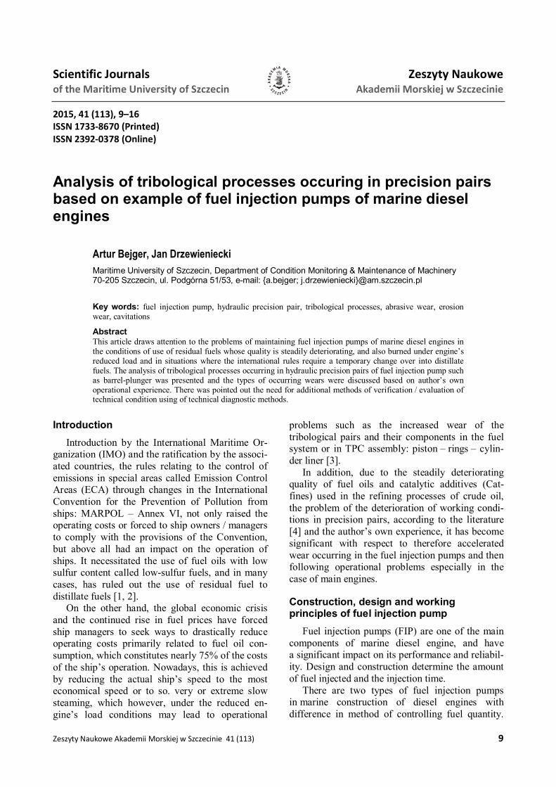
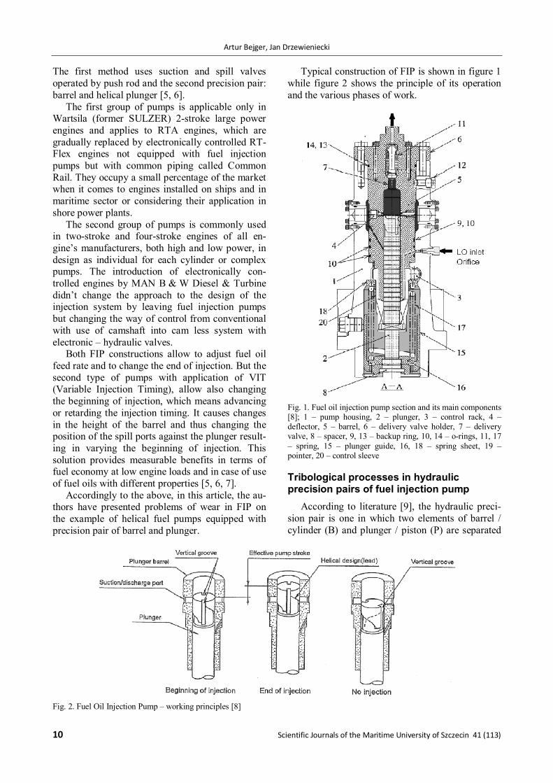
Typical construction of FIP is shown in figure 1 while figure 2 shows the principle of its operation and the various phases of work.
Tribological processes in hydraulic precision pairs of fuel injection pump
According to literature [9], the hydraulic preci-sion pair is one in which two elements of barrel / cylinder (B) and plunger / piston (P) are separated
Fig. 2. Fuel Oil Injection Pump – working principles [8]
Analysis of tribological processes occuring in precision pairs based on example of fuel injection pumps of marine Diesel engines
Zeszyty Naukowe Akademii Morskiej w Szczecinie 41 (113) 11
by working fluid for example fuel oil (F) forming the third structural element of machine and tribological node (FBP) (Fig. 3). Fuel oil in FIP simultaneously satisfy the functions of lubricating, cooling and sealing, working in an open system with recirculation allowing continuous flow of fresh fuel corresponding to feed rate. Thus, it is an element of FBP node which is the most susceptible to external / entrance forces (EF), and its quality and content of impurities significantly affects parameters of performance exit / output (PE) de-scribed by pump performance / efficiency (CP) and reflects on parameters of tribological exit / output (TE) characterizing tribological processes (TP).
Fig. 3. Physical model of FIP tribological node (FBP) [own study] Fk – kinetic forces, Fd – dynamic forces, Ft – thermal forces, Fe – environmental forces, Pi – features of FIP elements (FBP), Pu – pomp features, Ri – relations between pump’s elements, CP – pump output, TP – tribological processes
B-P elements during operation perform recipro-cating – rotational motion and tightness of assem-bly is not ensured by piston / sealing rings but by application of minimum radial clearances which are from 5 μm to 25 μm (50 micron limit) depending on cylinder liner bore / diameter and power achieved by one cylinder [8, 10]. Thus, the clear-
ance measure is a parameter binding responses of performance output (PE) and tribological exit (TE), whereas the input measures – external forces (EF) and performance output (PE) are dependent on operational demands / requirements (OD) relating to ordered ship’s speed (Fig. 4).
Processes in FBP tribological nodes of FIP are not homogeneous, and the occurrence and course of tribological wear determined by wear characteristics is non-linear and does not allow description in time domain function. In order to determine this, it is necessary therefore, to carry out detailed identification studies aimed at evaluation of extortion and properties determined by both design and quality of FIP components and their operation as well. Therefore, in the next chapter the wear processes occurring in FIP were analyzed.
Reasons and analysis of wear in fuel injection pumps
During operation of machine, it is convenient to adopt the following distribution of tribological wear processes: abrasive wear, adhesive wear, and wear by oxidation, fatigue wear, chemical and electro-chemical (corrosion) wear, cavitation wear and other types of wear. In general, there is no exclu-sive influence of particular wear process, but the most important is this leading. In FIP of marine diesel engines, impurities and characteristics of working fluids that are at the same time the lubri-cant liquid, have a decisive impact on proper func-tioning of hydraulic precision pair of FIP: barrel – plunger pair. This is due to the fact that, despite using of various fuel oil filtration methods starting from gravitational separation in settling tanks, through purification of water and solid impurities in centrifuges, ending at various filtering method with high accuracy and efficiency filters, it occurs that the total retention of impurities is impossible to achieve. This results because of disproportionate
Fig. 4. Logical model of FIP tribological pair (FBP) [own study]; vs – ship’s speed, vr – piston relative velocity, ar – piston relative acceleration, Fa – axial force acting on piston, tf – fuel temperature, pf – fuel pressure, – contamination level / concentration, t – working hours, TW – tribological wear
Artur Bejger, Jan Drzewieniecki
12 Scientific Journals of the Maritime University of Szczecin 41 (113)
effect resulting in increased resistance to the flow of liquid with increased accuracy and efficiency of filtering [9]. Thus, abrasive wear due to use of fuel oil containing in the impurities of different origins in the form of hard particles is the most common tribological wear process in FIP. Therefore, the deteriorating quality of fuel oils and the need to change / shifting from residual fuel oils called heavy fuel oils – HFO into distillate fuel oils called marine gas or diesel oils – MGO / MDO in emis-sion control areas will have a decisive influence on wear of FIP elements.
Typical / common wear occurring in FIP ele-ments are as follows: 1. Seizure of B-P hydraulic precision pair. 2. Jammed / sticking fuel rack and plunger. 3. Excessive abrasive wear of B-P pair. 4. Wear of delivery valve. 5. Erosion wears of plunger, deflector and end cap.
They are summarized in table 1, which shows the possible causes leading to these kinds of wear and the possible remedies.
Furthermore, cracks may occur occasionally in barrel and pump housing [4, 7, 11].
Seizure of B-P hydraulic precision pair
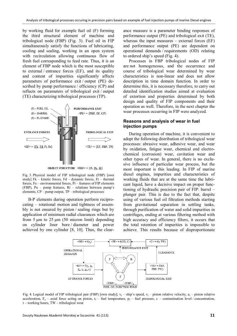
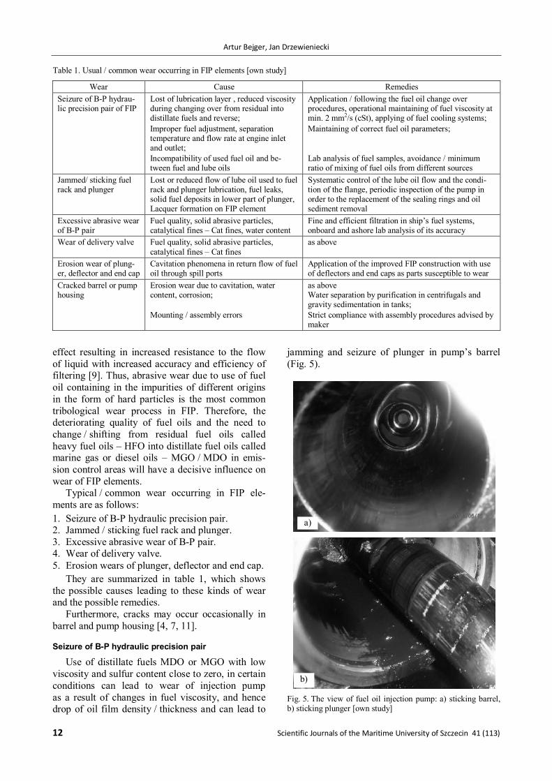
Use of distillate fuels MDO or MGO with low viscosity and sulfur content close to zero, in certain conditions can lead to wear of injection pump as a result of changes in fuel viscosity, and hence drop of oil film density / thickness and can lead to
jamming and seizure of plunger in pump’s barrel (Fig. 5).
Fig. 5. The view of fuel oil injection pump: a) sticking barrel, b) sticking plunger [own study]
Table 1. Usual / common wear occurring in FIP elements [own study]
Wear Cause Remedies Seizure of B-P hydrau-lic precision pair of FIP
Lost of lubrication layer , reduced viscosity during changing over from residual into distillate fuels and reverse; Improper fuel adjustment, separation temperature and flow rate at engine inlet and outlet; Incompatibility of used fuel oil and be-tween fuel and lube oils
Application / following the fuel oil change over procedures, operational maintaining of fuel viscosity at min. 2 mm2/s (cSt), applying of fuel cooling systems; Maintaining of correct fuel oil parameters; Lab analysis of fuel samples, avoidance / minimum ratio of mixing of fuel oils from different sources
Jammed/ sticking fuel rack and plunger
Lost or reduced flow of lube oil used to fuel rack and plunger lubrication, fuel leaks, solid fuel deposits in lower part of plunger, Lacquer formation on FIP element
Systematic control of the lube oil flow and the condi-tion of the flange, periodic inspection of the pump in order to the replacement of the sealing rings and oil sediment removal
Excessive abrasive wear of B-P pair
Fuel quality, solid abrasive particles, catalytical fines – Cat fines, water content
Fine and efficient filtration in ship’s fuel systems, onboard and ashore lab analysis of its accuracy
Wear of delivery valve Fuel quality, solid abrasive particles, catalytical fines – Cat fines
as above
Erosion wear of plung-er, deflector and end cap
Cavitation phenomena in return flow of fuel oil through spill ports
Application of the improved FIP construction with use of deflectors and end caps as parts susceptible to wear
Cracked barrel or pump housing
Erosion wear due to cavitation, water content, corrosion; Mounting / assembly errors
as above Water separation by purification in centrifugals and gravity sedimentation in tanks; Strict compliance with assembly procedures advised by maker
a)
b)
Analysis of tribological processes occuring in precision pairs based on example of fuel injection pumps of marine Diesel engines
Zeszyty Naukowe Akademii Morskiej w Szczecinie 41 (113) 13
Seizure of B-P hydraulic precision pair of FIP occurs then if the clearance between plunger and barrel is reduced or if there is lack of lubrication. Thus, the most common cause of jamming and seizure in FIP are the excessive changes in fuel temperature during changing over the fuel different grades while having to go from distillate into resid-ual fuels, and vice versa. Preventing method for the occurrence of such phenomena comes down to operational reduction of fuel viscosity to a mini-mum 2 mm2/s (cSt), and in special cases to applica-tion / installation of fuel cooling systems. Engine manufacturers recommend that the rate of fuel temperature changes does not exceed 2C per minute which can be done by automatically control-ling temperature or viscosity with simultaneous manual change of fuel temperature [1, 2, 8].
Jammed / sticking fuel rack and plunger
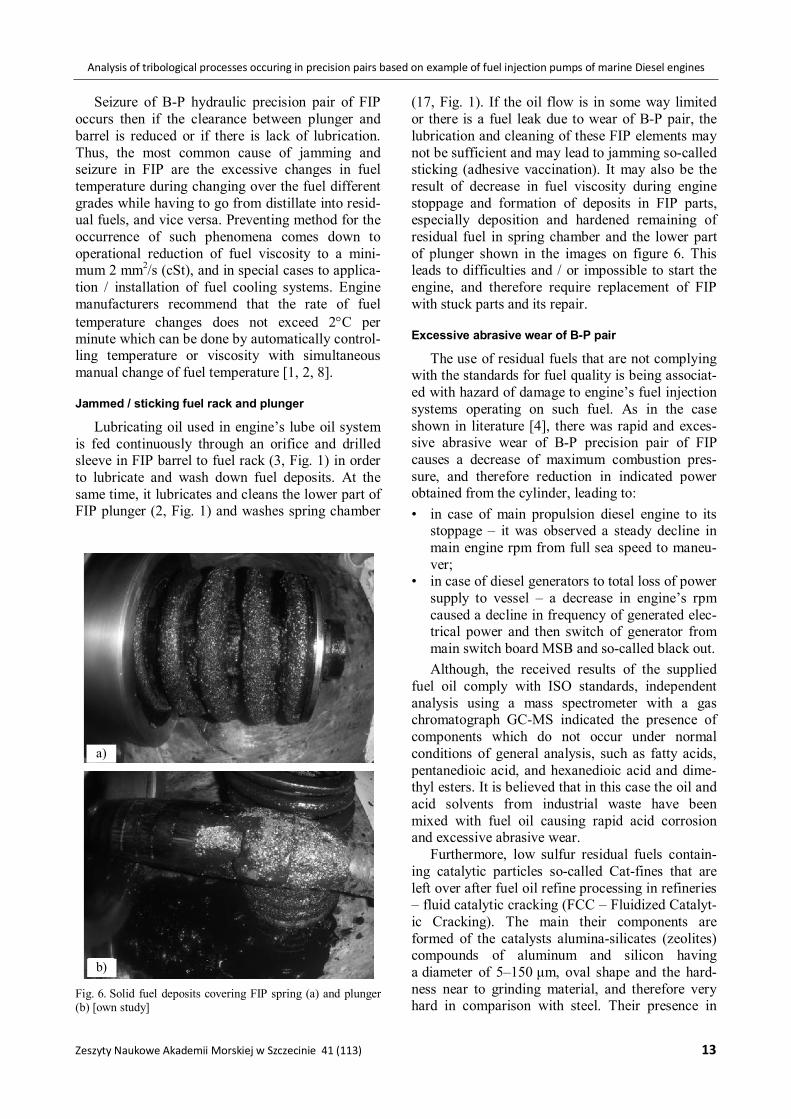
Lubricating oil used in engine’s lube oil system is fed continuously through an orifice and drilled sleeve in FIP barrel to fuel rack (3, Fig. 1) in order to lubricate and wash down fuel deposits. At the same time, it lubricates and cleans the lower part of FIP plunger (2, Fig. 1) and washes spring chamber
(17, Fig. 1). If the oil flow is in some way limited or there is a fuel leak due to wear of B-P pair, the lubrication and cleaning of these FIP elements may not be sufficient and may lead to jamming so-called sticking (adhesive vaccination). It may also be the result of decrease in fuel viscosity during engine stoppage and formation of deposits in FIP parts, especially deposition and hardened remaining of residual fuel in spring chamber and the lower part of plunger shown in the images on figure 6. This leads to difficulties and / or impossible to start the engine, and therefore require replacement of FIP with stuck parts and its repair.
Excessive abrasive wear of B-P pair
The use of residual fuels that are not complying with the standards for fuel quality is being associat-ed with hazard of damage to engine’s fuel injection systems operating on such fuel. As in the case shown in literature [4], there was rapid and exces-sive abrasive wear of B-P precision pair of FIP causes a decrease of maximum combustion pres-sure, and therefore reduction in indicated power obtained from the cylinder, leading to: • in case of main propulsion diesel engine to its
stoppage – it was observed a steady decline in main engine rpm from full sea speed to maneu-ver;
• in case of diesel generators to total loss of power supply to vessel – a decrease in engine’s rpm caused a decline in frequency of generated elec-trical power and then switch of generator from main switch board MSB and so-called black out. Although, the received results of the supplied
fuel oil comply with ISO standards, independent analysis using a mass spectrometer with a gas chromatograph GC-MS indicated the presence of components which do not occur under normal conditions of general analysis, such as fatty acids, pentanedioic acid, and hexanedioic acid and dime-thyl esters. It is believed that in this case the oil and acid solvents from industrial waste have been mixed with fuel oil causing rapid acid corrosion and excessive abrasive wear.
Furthermore, low sulfur residual fuels contain-ing catalytic particles so-called Cat-fines that are left over after fuel oil refine processing in refineries – fluid catalytic cracking (FCC – Fluidized Catalyt-ic Cracking). The main their components are formed of the catalysts alumina-silicates (zeolites) compounds of aluminum and silicon having a diameter of 5–150 μm, oval shape and the hard-ness near to grinding material, and therefore very hard in comparison with steel. Their presence in
Fig. 6. Solid fuel deposits covering FIP spring (a) and plunger (b) [own study]
b)
a)
Artur Bejger, Jan Drzewieniecki
14 Scientific Journals of the Maritime University of Szczecin 41 (113)
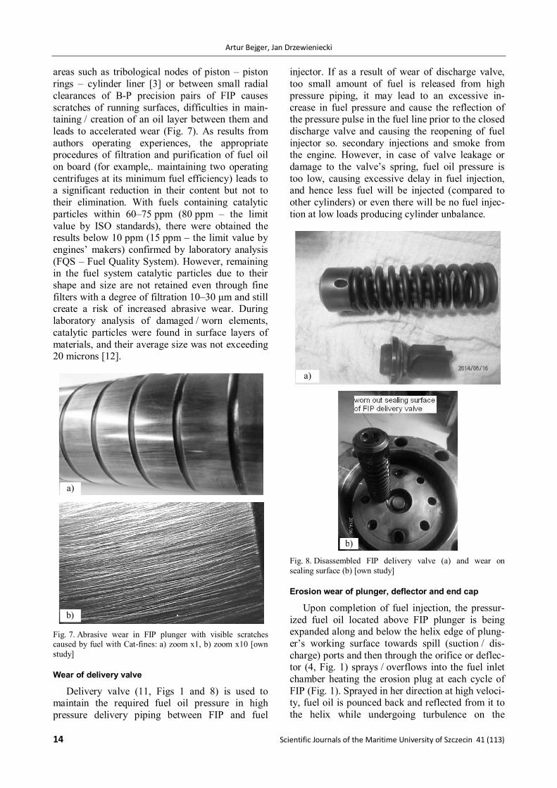
areas such as tribological nodes of piston – piston rings – cylinder liner [3] or between small radial clearances of B-P precision pairs of FIP causes scratches of running surfaces, difficulties in main-taining / creation of an oil layer between them and leads to accelerated wear (Fig. 7). As results from authors operating experiences, the appropriate procedures of filtration and purification of fuel oil on board (for example,. maintaining two operating centrifuges at its minimum fuel efficiency) leads to a significant reduction in their content but not to their elimination. With fuels containing catalytic particles within 60–75 ppm (80 ppm – the limit value by ISO standards), there were obtained the results below 10 ppm (15 ppm – the limit value by engines’ makers) confirmed by laboratory analysis (FQS – Fuel Quality System). However, remaining in the fuel system catalytic particles due to their shape and size are not retained even through fine filters with a degree of filtration 10–30 μm and still create a risk of increased abrasive wear. During laboratory analysis of damaged / worn elements, catalytic particles were found in surface layers of materials, and their average size was not exceeding 20 microns [12].
Fig. 7. Abrasive wear in FIP plunger with visible scratches caused by fuel with Cat-fines: a) zoom x1, b) zoom x10 [own study]
Wear of delivery valve
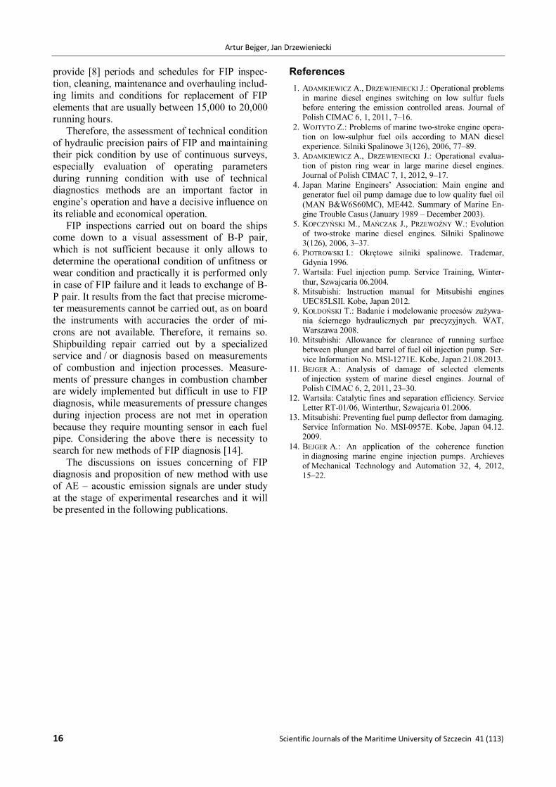
Delivery valve (11, Figs 1 and 8) is used to maintain the required fuel oil pressure in high pressure delivery piping between FIP and fuel
injector. If as a result of wear of discharge valve, too small amount of fuel is released from high pressure piping, it may lead to an excessive in-crease in fuel pressure and cause the reflection of the pressure pulse in the fuel line prior to the closed discharge valve and causing the reopening of fuel injector so. secondary injections and smoke from the engine. However, in case of valve leakage or damage to the valve’s spring, fuel oil pressure is too low, causing excessive delay in fuel injection, and hence less fuel will be injected (compared to other cylinders) or even there will be no fuel injec-tion at low loads producing cylinder unbalance.
Fig. 8. Disassembled FIP delivery valve (a) and wear on sealing surface (b) [own study]
Erosion wear of plunger, deflector and end cap
Upon completion of fuel injection, the pressur-ized fuel oil located above FIP plunger is being expanded along and below the helix edge of plung-er’s working surface towards spill (suction / dis-charge) ports and then through the orifice or deflec-tor (4, Fig. 1) sprays / overflows into the fuel inlet chamber heating the erosion plug at each cycle of FIP (Fig. 1). Sprayed in her direction at high veloci-ty, fuel oil is pounced back and reflected from it to the helix while undergoing turbulence on the
a)
b)
a)
b)
Analysis of tribological processes occuring in precision pairs based on example of fuel injection pumps of marine Diesel engines
Zeszyty Naukowe Akademii Morskiej w Szczecinie 41 (113) 15
plunger’s working surface which produces on its and deflector edges rapid drop of pressure and the phenomenon of cavitation (Fig. 9).
Fig. 9. Cavitation / erosion phenomena in barrel-plunger pair of FIP [7]
It causes erosive wear just above the helix edge of the plunger’s working surface (Fig. 10), and on the surfaces of deflector and erosion plug being called “weak link” that is part of structurally de-signed to be worn by erosive wear.
Fig. 10. Erosion wears above hex edge of plunger working surface caused by cavitation phenomena; a) zoom x1, b) zoom x10 [own study]
B-P precision pair should be replaced if the depth of erosion on the plunger’s working surface is 0.5 mm and / or its location is at a distance of less than 0.8 mm from the helix edge, as such a wear of plunger reduces the efficiency of B-P pair sealing. Typically, it is a design problem that the effect can be minimized by use of reducing fuel flow orifices called deflectors. These are the ele-ments, which are also subject to wear over time and require replacement during FIP maintenance (Fig. 11).
Fig. 11. The example of FIP new and damaged deflector [13]
Conclusions As it results from studies and elaborations in-
cluded in the engine manufacturer’s service infor-mation, researches of damages carried out at ship managers’ request [4] and the authors’ own experi-ence [11] the number of accidents involving FIP installed in marine diesel engines is steadily increasing. This has a large impact on engines performance particularly operating at low loads because, as it was said the inner wear of hydraulic precision pair of FIP entails a reduction in fuel oil feed rate and in maximum pressure generated by injection pump and causes a delay in injection, and thus the atomized fuel oil droplet size increases and also degrade the mixing conditions of fuel oil mist with compressed air as fuel oil is injected into the combustion chamber at the moment of higher pressure.
Although due to tribological processes, the in-ternal wear in B-P pair is unavoidable, as it is apparent from the presented analysis of tribological processes occurring in FIP, the degree and progress of tribological wear are largely dependent on opera-tional and maintenance conditions, and they are strongly dependent on use of fuel oil quality and possibility of its purification and filtration in marine installations.
Currently, FIP inspections are carried out with accordance to TBO (time between overhauling) that is based on working hours. Manufacturers shall
a)
b)
Artur Bejger, Jan Drzewieniecki
16 Scientific Journals of the Maritime University of Szczecin 41 (113)
provide [8] periods and schedules for FIP inspec-tion, cleaning, maintenance and overhauling includ-ing limits and conditions for replacement of FIP elements that are usually between 15,000 to 20,000 running hours.
Therefore, the assessment of technical condition of hydraulic precision pairs of FIP and maintaining their pick condition by use of continuous surveys, especially evaluation of operating parameters during running condition with use of technical diagnostics methods are an important factor in engine’s operation and have a decisive influence on its reliable and economical operation.
FIP inspections carried out on board the ships come down to a visual assessment of B-P pair, which is not sufficient because it only allows to determine the operational condition of unfitness or wear condition and practically it is performed only in case of FIP failure and it leads to exchange of B-P pair. It results from the fact that precise microme-ter measurements cannot be carried out, as on board the instruments with accuracies the order of mi-crons are not available. Therefore, it remains so. Shipbuilding repair carried out by a specialized service and / or diagnosis based on measurements of combustion and injection processes. Measure-ments of pressure changes in combustion chamber are widely implemented but difficult in use to FIP diagnosis, while measurements of pressure changes during injection process are not met in operation because they require mounting sensor in each fuel pipe. Considering the above there is necessity to search for new methods of FIP diagnosis [14].
The discussions on issues concerning of FIP diagnosis and proposition of new method with use of AE – acoustic emission signals are under study at the stage of experimental researches and it will be presented in the following publications.
References 1. ADAMKIEWICZ A., DRZEWIENIECKI J.: Operational problems
in marine diesel engines switching on low sulfur fuels before entering the emission controlled areas. Journal of Polish CIMAC 6, 1, 2011, 7–16.
2. WOJTYTO Z.: Problems of marine two-stroke engine opera-tion on low-sulphur fuel oils according to MAN diesel experience. Silniki Spalinowe 3(126), 2006, 77–89.
3. ADAMKIEWICZ A., DRZEWIENIECKI J.: Operational evalua-tion of piston ring wear in large marine diesel engines. Journal of Polish CIMAC 7, 1, 2012, 9–17.
4. Japan Marine Engineers’ Association: Main engine and generator fuel oil pump damage due to low quality fuel oil (MAN B&W6S60MC), ME442. Summary of Marine En-gine Trouble Casus (January 1989 – December 2003).
5. KOPCZYŃSKI M., MAŃCZAK J., PRZEWOŹNY W.: Evolution of two-stroke marine diesel engines. Silniki Spalinowe 3(126), 2006, 3–37.
6. PIOTROWSKI I.: Okrętowe silniki spalinowe. Trademar, Gdynia 1996.
7. Wartsila: Fuel injection pump. Service Training, Winter-thur, Szwajcaria 06.2004.
8. Mitsubishi: Instruction manual for Mitsubishi engines UEC85LSII. Kobe, Japan 2012.
9. KOŁDOŃSKI T.: Badanie i modelowanie procesów zużywa-nia ściernego hydraulicznych par precyzyjnych. WAT, Warszawa 2008.
10. Mitsubishi: Allowance for clearance of running surface between plunger and barrel of fuel oil injection pump. Ser-vice Information No. MSI-1271E. Kobe, Japan 21.08.2013.
11. BEJGER A.: Analysis of damage of selected elements of injection system of marine diesel engines. Journal of Polish CIMAC 6, 2, 2011, 23–30.
12. Wartsila: Catalytic fines and separation efficiency. Service Letter RT-01/06, Winterthur, Szwajcaria 01.2006.
13. Mitsubishi: Preventing fuel pump deflector from damaging. Service Information No. MSI-0957E. Kobe, Japan 04.12. 2009.
14. BEJGER A.: An application of the coherence function in diagnosing marine engine injection pumps. Archieves of Mechanical Technology and Automation 32, 4, 2012, 15–22.