American Journal of Mechanical and Materials Engineering 2017; 1(2): 49-57 http://www.sciencepublishinggroup.com/j/ajmme doi: 10.11648/j.ajmme.20170102.14 Analytical and Numerical Modeling of Hot Machining of Inconel 718 Asit Kumar Parida Mechanical Engineering Department, National Institute of Technology Rourkela, Odisha, India Email address: [email protected]To cite this article: Asit Kumar Parida. Analytical and Numerical Modeling of Hot Machining of Inconel 718. American Journal of Mechanical and Materials Engineering. Vol. 1, No. 2, 2017, pp. 49-57. doi: 10.11648/j.ajmme.20170102.14 Received: March 13, 2017; Accepted: April 8, 2017; Published: June 2, 2017 Abstract: The comparison of an analytical and numerical method to calculate the plastic strain, shear angle, and chip tool contact length in hot machining of Inconel 718 using flame heating has been discussed in the present study. The workpiece was heated with the combination of liquid petroleum gas along with oxygen gas. Merchant analytical model has been utilized for calculation of plastic strain, shear angle, while Sutter model is used for chip-tool contact length. DEFORM software has been used to find out the chip-tool contact length (L), shear angle ( φ ), shear strain ( ε ) in the numerical model. It was observed that shear angle and chip tool contact length increased and plastic strain decreased with the increase of cutting speed and feed rate. From the numerical study, a good correlation was found for shear angle, chip tool contact length with the analytical model. Keywords: FEM, Plastic Strain, Inconel 718, Shear Angle, Chip-Tool Contact Length 1. Introduction Nickel-base alloys are widely applied nowadays due to its mechanical characteristics (high strength, corrosion resistance, excellent creep, and fatigue strength at high temperature), it’s the alloy with more applicability among all nickel base alloys. Thus these alloys are widely used in jet engines, steam generators, gas turbines and nuclear reactors [1]. But the alloy has a hard abrasive particle in the microstructure, low thermal conductivity, and low elastic modulus which makes difficult during machining operations [2]. In all manufacturing process, machining is the vital role for making the product. It’s a material with poor machinability and has proven wide research on machining of these hard materials. The hot machining process is being used for machining hard materials, where maintaining tool wears reduction less is extremely importance. It presents several advantages besides high material removal rates, enhances tool life, increases chip-tool contact length, better surface finish as well [3]. In hot machining, the application of external heat is imposed to the surface of the workpiece. So an increase of temperature at cutting zone softens the material, allowing for better removal rate, less cutting force, and tool wear. However, this is possible for optimum heating temperature on the workpiece. Otherwise, rapid tool wear and damage to the surface of the workpiece occured. Other heating methods like electric arc heating, induction heating [4], plasma [5], laser [6], furnace heating [7] and flame heating[8,9] etc. have been used for heating the workpiece. However due to high cost, skilled labour and large space requirement newly developed heating method like plasma, laser etc. are not widely used in machining industries, although these techniques are secure. All heating methods have some benefits and some disadvantages according to their usages [10]. The material deformation is a great influence on the plastic strain rate and temperature. From the past literature, it is mentioned that the adiabatic shear band formation along with shear localization occurs at high strain rate whereas slip or twinning mechanism occurs deformation at Low strain rate. The dislocation motion of particle within the lattice over a wide range of cutting temperature and strain rate are the mechanism of plastic deformation [11]. The chip formation and deformation mechanism of a material depend on upon the hardness of the material and the plastic strain rate increase with the increase of cutting speed reported by duan et al. [12]. The accuracy of determination of plastic strains in machining operation depends on upon the distortion of grids
Transcript
American Journal of Mechanical and Materials Engineering 2017; 1(2): 49-57 http://www.sciencepublishinggroup.com/j/ajmme doi: 10.11648/j.ajmme.20170102.14
Analytical and Numerical Modeling of Hot Machining of Inconel 718
Asit Kumar Parida
Mechanical Engineering Department, National Institute of Technology Rourkela, Odisha, India
To cite this article: Asit Kumar Parida. Analytical and Numerical Modeling of Hot Machining of Inconel 718. American Journal of Mechanical and Materials
Engineering. Vol. 1, No. 2, 2017, pp. 49-57. doi: 10.11648/j.ajmme.20170102.14
Received: March 13, 2017; Accepted: April 8, 2017; Published: June 2, 2017
Abstract: The comparison of an analytical and numerical method to calculate the plastic strain, shear angle, and chip tool contact length in hot machining of Inconel 718 using flame heating has been discussed in the present study. The workpiece was heated with the combination of liquid petroleum gas along with oxygen gas. Merchant analytical model has been utilized for calculation of plastic strain, shear angle, while Sutter model is used for chip-tool contact length. DEFORM software has been used to find out the chip-tool contact length (L), shear angle (φ ), shear strain ( ε ) in the numerical model. It was observed that
shear angle and chip tool contact length increased and plastic strain decreased with the increase of cutting speed and feed rate. From the numerical study, a good correlation was found for shear angle, chip tool contact length with the analytical model.
Nickel-base alloys are widely applied nowadays due to its mechanical characteristics (high strength, corrosion resistance, excellent creep, and fatigue strength at high temperature), it’s the alloy with more applicability among all nickel base alloys. Thus these alloys are widely used in jet engines, steam generators, gas turbines and nuclear reactors [1]. But the alloy has a hard abrasive particle in the microstructure, low thermal conductivity, and low elastic modulus which makes difficult during machining operations [2]. In all manufacturing process, machining is the vital role for making the product. It’s a material with poor machinability and has proven wide research on machining of these hard materials. The hot machining process is being used for machining hard materials, where maintaining tool wears reduction less is extremely importance. It presents several advantages besides high material removal rates, enhances tool life, increases chip-tool contact length, better surface finish as well [3]. In hot machining, the application of external heat is imposed to the surface of the workpiece. So an increase of temperature at cutting zone softens the material, allowing for better removal rate, less cutting force, and tool wear. However, this is possible for optimum heating temperature on the workpiece. Otherwise, rapid tool wear
and damage to the surface of the workpiece occured. Other heating methods like electric arc heating, induction heating [4], plasma [5], laser [6], furnace heating [7] and flame heating[8,9] etc. have been used for heating the workpiece. However due to high cost, skilled labour and large space requirement newly developed heating method like plasma, laser etc. are not widely used in machining industries, although these techniques are secure. All heating methods have some benefits and some disadvantages according to their usages [10].
The material deformation is a great influence on the plastic strain rate and temperature. From the past literature, it is mentioned that the adiabatic shear band formation along with shear localization occurs at high strain rate whereas slip or twinning mechanism occurs deformation at Low strain rate. The dislocation motion of particle within the lattice over a wide range of cutting temperature and strain rate are the mechanism of plastic deformation [11]. The chip formation and deformation mechanism of a material depend on upon the hardness of the material and the plastic strain rate increase with the increase of cutting speed reported by duan et al. [12]. The accuracy of determination of plastic strains in machining operation depends on upon the distortion of grids
American Journal of Mechanical and Materials Engineering 2017; 1(2): 49-57 50
[13]. Effect of nose radius on cutting force and process variables in hot machining studied by Parida et al. [14] using DEFORM software. They stated that increase of nose radius decrease the shear angle and increase the chip thickness value. Chip-tool contact phenomena occur when the chip is flow on the of rake surface of the tool. Chip-tool contact length defined the shear angle, undeformed chip thickness [15]. A lot of work has been done on the chip-tool contact length of the cutting tool. It was found from the literature review that almost all model of the chip-tool interface does not depend on upon the cutting velocity. Zadshakoyan and Pourmostaghimi et al. [16] analysed the significant effect of chip-tool contact length on various machining responses using genetic algorithms. They stated that the decrease of cutting temperature and cutting force is due to a decrease of chip-tool contact length, which further decrease the secondary shear zone. Using different cutting speed, Iqbal et al. [17] studied the chip-tool contact length of two different material i.e. AISI 1045 and Ti-6A-l4V. The size of heat transfer zone in the cutting zone affected by the chip-tool contact length. They observed that with the increasing of cutting speed, the contact length decrease in the case of AISI 1045 but, tool-chip contact length increases with the increase of cutting speed. The use of flame heating on machining of hard materials studied by different researchers [8, 18, 9, 19, 20] and different model has been used for cutting force, tool wear, surface roughness. But the research on plastic strain, chip-tool contact length and shear angle has lack behind. Further, author best knowledge, less work has been studied numerically in hot machining area. The aim is to study the behavior (shear angle, chip-tool contact length, and plastic strain) of Inconel 718 steel in hot machining and predicted values shows good correlation with the analytical results.
2. Experimental Procedure
The experimental trials were carried out with the help of center lathe of 6 hp spindle power and maximum spindle speed of 1200 rpm. Inconel 718 was chosen as sample material having diameter 50 mm and length of 300 mm. The hardness was around 38 - 42 HRC as received from the supplier. The chemical composition of the sample material is shown (Table 1). Uncoated carbide tool was used for all experiment. The specification of cutting tool geometry, cutting condition and physical properties of Inconel 718 are tabulated in Table 2 and Table 3 respectively. The workpiece was heated using liquefied petroleum gas (LPG) and combined with oxygen. The workpiece was heated to 600°C temperature as the yield strength of Inconel 718 decreases at this temperature studied in past literature [21–23]. The workpiece was drilled and bored with boring tool up to 47 mm and orthogonal machining conditions were performed.
Table 1. Chemical composition of Inconel 718(weight%) [24].
Table 2. Specification of cutting tool geometry and cutting condition.
Workpiece material Cutting tool
material Inconel 718 Cemented carbide
Rake angle -6° Clearance angle 6° Principal cutting edge angle 75° Nose radius 0.4 mm Machining condition Cutting speed 60, 100 m/min Feed rate 0.1, 0.15 mm/rev Depth of cut 0.5 mm Environment Heating temperature of 600°C
Table 3. Mechanical and Physical Properties of Inconel 718 [25].
Density [kg/m3] 8200 Latent heat of melting [J/kg] 250,000 Solidus temperature [K] 1528 Liquidus temperature [K] 1610 Specific heat capacity 600 Thermal conductivity [W/m.k] at 1500 K 30 Poisson’s ratio 0.3
Figure 1. Experimental setup for hot machining [a] Optical microscope [b].
The experiments were carried out with cutting velocity of 40-100 m/min, the feed of 0.10-0.15 mm/rev and 0.5 mm constant depth of cut. After each run, the chips were collected and chip thickness, chip-tool contact length were measured with the help of nikon toolmaker’s microscope. The experimental setup and Nikon tool maker microscope is shown in Figure 1.
3. Analytical Model
Merchant theory is used to calculate the plastic strain, shear angle, chip thickness ratio in this study and Sutter model is used for chip-tool contact length calculation. The chip thickness ratio (r) can be calculated as
c
tr
t= (1)
where t is chip thickness and c
t is the uncut chip thickness
and can be calculated as
*sin c
t f γ= (2)
where f is feed rate and γ is the principal cutting angle.
The shear angle (φ ) in the shear plane can be calculated
as
51 Asit Kumar Parida: Analytical and Numerical Modeling of Hot Machining of Inconel 718
costan
sinr
αφα
− = − (3)
where α is the rake angle. The plastic strain ( ε ) can be calculated as
21 2 sin
cos
r r
r
αεα
+ −= (4)
0cos( 6)tan tan (0.31) 17
3.10 sin( 6)φ − − −= = = − −
21 3.1 2*3.1*sin( 6)3.65
3.1*cos( 6)ε + − −= =
−
Chip-tool contact length (c
L ) can be calculated as per
Sutter et al. [26]
1.92 0.09c c
L t t= − (5)
1.92*0.0965 0.09*0.3 0.158 c
L mm= − =
4. Finite Element Analysis in Hot
Machining Operation
The finite element analysis in hot turning operation has carried out with DEFORM software, supplied by Scientific Forming Technologies Corporation (SFTC) is used in this work. The software contains metal cutting, metal forming, heat treatment, machining distortion, in both two and three dimensions.
Figure 2. Meshing and boundary conditions.
In hot machining simulation, a cylindrical heat exchange window was used to exchange heat in the process. The heat exchange window moves along the cutting direction and maintain temperature (600°C in the case of hot machining) set by the user and another surface kept at room temperature. The black arrow mark indicates heat transfer to the environment while the other surface which is far away from the cutting zone maintains room temperature. No movement of the workpiece along y-direction was marked by black triangle, while for cutting tool both x and y-direction was constraint represented by the red triangle as shown in Figure 2. The workpiece was modeled as plastic with 30,000 elements, whereas tool was modeled as rigid with 20,000 elements. For better accurate result of plastic strain, temperature distribution, the cutting zone area was assigned with high mesh density with minimum element size 2µm. Johnson-cook material modeling was implemented, a well-known and widely used by many researchers [27].
{ }.
.
0
1 ln 1
m
n r
m r
T TA B C
T T
εσ εε
− = + + − −
(6)
where σ is the flow stress, .
ε is the plastic strain, .
ε is the
plastic strain rate, .
0ε is the reference plastic strain rate. m
T is
the melting point of the material, Tr is the room temperature
and T is the temperature of the workpiece material. A, B, C are the yield strength, hardening modulus, and strain rate sensitivity coefficient, n is the hardening coefficient and m is the thermal softening coefficient. The Johnson-Cook material constants are tabulated in Table 4.
Table 4. Johnson-cook material constant [28].
A [MPa] B [MPa] n C m
450 1700 0.65 0.017 1.3
In the present study, constant shear friction model is used in the simulation and value of shear friction factor (m) was taken 0.9 [29] as Eq.7.
mk
τ= (7)
where τ = Shear stress, k = shear flow stress of the work material
Damage criteria have been implemented using Cockroft and Latham model, as Inconel 718 is low thermal conductivity material and chip segmentation nature and evaluated as Eq.8.
0
fC d
i
εσσ εσ
− − = ∫ −
(8)
American Journal of Mechanical and Materials Engineering 2017; 1(2): 49-57 52
where Ci is the critical damage [28], fε is the strain at the
breaking conditions, ε−
is the effective strain, σ−
is the effective stress and σ is the maximum stress.
For modeling of hot machining of a heat exchange window was used to exchange heat in a local area which is available in DEFORM software. The total power input, through the window can be expressed as [30] Eq.9.
( )window workpieceq hA T T= − (9)
where, A is the surface area of heat exchange window (described as red cylinder), h is the heat conventional coefficient,
windowT is the temperature of the heat exchange
window and workpieceT is the temperature of the workpiece.
The detail work plan is shown in Figure 3.
Figure 3. Detail work plans in this study.
5. Results and Discussion
The simulated results (plastic strain, shear angle, chip-tool contact length) obtained in DEFORM software at different machining conditions were validated with different analytical model (Merchant and Sutter).
5.1. Shear Angle
The computed shear angle at different cutting condition is shown in Figure 4. It was noticed that with an increase of
cutting speed and feed rate the shear angle increase. The shear angle at cutting conditions of 60 (m/min)/0.1 (mm/rev) and 100 (m/min)/0.15 (mm/rev) were overestimated from the analytical result, whereas at 100 (m/min)/0.1 (mm/rev) cutting condition it was underestimated from the analytical result. At 60 m/min and 0.15 mm/rev cutting condition, the shear angle was good agreement between the numerical and analytical result as shown in Figure 5. The increase of shear angle is the sign of the reduction of cutting force during hot machining.
Figure 4. Shear angle at different cutting conditions.
53 Asit Kumar Parida: Analytical and Numerical Modeling of Hot Machining of Inconel 718
Figure 5. Comparison between the simulated and analytical shear angle at different cutting conditions.
5.2. Plastic Strain
As workpiece material is suffered by both thermal softening and reduction of friction due to an increase of cutting speed from 60 -100 m/min, the plastic strain at V=60 m/min (3.65) is reduced to at V=100 m/min (2.7) in the analytical method. But at a constant speed, with an increase of feed rate (0.1 to 0.15 mm/rev) the plastics strain decreased
from (3.65 to 2.74). Except at V=100 m/min and f=0.10 mm/rev, the numerical plastic strain value was overestimated compared to the analytical result. The numerical plastic strain at different cutting conditions is shown in Figure 6. The comparison between the simulated and analytical model for plastic strain result as shown in Figure 7.
Figure 6. Numerical plastic strain distribution in the workpiece and chip at different cutting conditions.
American Journal of Mechanical and Materials Engineering 2017; 1(2): 49-57 54
Figure 7. Comparison between the simulated and analytical plastic strain value at different cutting conditions.
5.3. Chip-Tool Contact Length
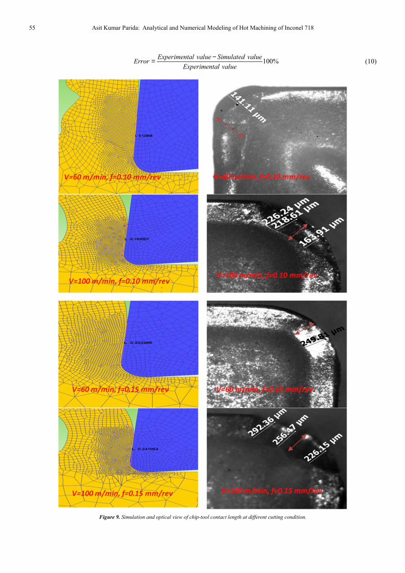
Iqbal et al. [17] studied the contact tool-chip length using finite element simulation of machining of steel. They used a different model for contact length and Marino's model was the best result for turning of AISI 1045 steel. They stated that friction factor has a big role in chip-tool contact length. During hot machining (600°C), the friction between the chip-tool decreased compared to room temperature machining. The chip-tool contact length measurement in the simulation is shown in Figure 8. It was observed that with an increase of cutting speed and feed rate the chip-tool contact length
increased. The increase of chip-tool contact length has many benefit like normal stress acting on the tool becomes lower and improve tool life [3]. The analytical result finds close agreement with the simulation results. Chip-tool contact length in simulation and experiment are shown in Figure 9 and Figure 10 respectively. The comparison between the analytical, simulation and experiment chip-tool contact length results (Figure 11). The analytical and predicted shear angle, chip-tool contact length, plastic strain values are tabulated in Table 5. The error % between the experiment and simulated value were calculated using Eq.9 and tabulated in Table 6.
Figure 8. Chip-tool contact length in simulation.
55 Asit Kumar Parida: Analytical and Numerical Modeling of Hot Machining of Inconel 718
100%
Experimental value Simulated valueError
Experimental value
−= (10)
Figure 9. Simulation and optical view of chip-tool contact length at different cutting condition.
American Journal of Mechanical and Materials Engineering 2017; 1(2): 49-57 56
Figure 10. Comparison between the Numerical, Analytical, and Experimental chip-tool contact length.
Table 5. Calculated and Predicted shear angle, plastic strain, and chip-tool contact length.
Machining conditions Analytical
plastic strain
Simulated
plastic strain
Analytical shear
angle (°)
Simulated shear
angle (°)
Analytical chip-tool
contact length
Simulated chip-
tool contact length
V=60m/min, f =0.10 mm/rev 3.65 4.03 17 19.7 0.158 0.123
f =0.15 mm/rev 2.74 3.32 25 24.9 0.25 0.22
V=100m/min f =0.10 mm/rev 2.70 2.73 25 20.1 0.16 0.15
f =0.15 mm/rev 2.48 2.82 29 31.4 0.25 0.24
The Comparison between analytical and simulated values
for shear angle, plastic strain, chip tool contact length at hot machining and its error percentage is tabulated in Table 4. The error % of plastic strain was higher at cutting speed of 60 m/min and feed rate of 0.15 mm/rev, for the shear angle at 100(m/min)/0.10(mm/rev) and for chip-tool contact length at 60(m/min)/0.1(mm/rev) cutting condition respectively.
Table 6. Errors percentage between the analytical and simulated conditions.
Machining
conditions
Plastic
strain (%)
Shear angle
(%)
Chip-tool contact
length (%)
V=60m/min, f =0.10 mm/rev
10 15 22
V=60m/min, f =0.15 mm/rev
21 0.4 12
V=100m/min, f =0.10 mm/rev
1 19.6 6.25
V=100m/min, f=0.15 mm/rev
13 8.27 4
6. Conclusions
In this present work, hot machining of Inconel 718 has been studied using the gas flame heating method. An analytical studied has been carried out using Merchant and Sutter model to find out plastic strain, shear angle, and chip-tool contact length. Numerical analysis was also carried out to study the strain, shear angle and chip-tool contact length using DEFORM software at different cutting conditions
(both room and heated). Numerical modeling and simulation of machining process variables has advantage that it provides possibilities to simulate the machining process. The input data and boundary conditions is the main criteria for accuracy. The model is verified with the analytical model data of chip tool contact length, shear angle, plastic strain. From the analysis, it was observed that the plastic strain value decreased, Shear angle and chip-tool contact length value increased with increase of cutting speed and feed rate. The maximum error % between the experimental and simulation for plastic strain was observed at cutting conditions of v=60m/min, f=0.10mm/rev, for shear angle 19.6% error at v=100m/min, f=0.10 mm/rev and for chip-tool contact length 22% error at v=60m/min, f=0.10mm/rev respectively.
References
[1] Ezugwu EO. High speed machining of aero-engine alloys. J Brazilian Soc Mech Sci Eng 2004;26:1–11. doi:10.1590/S1678-58782004000100001.
[2] Ezugwu EO. Key improvements in the machining of difficult-to-cut aerospace superalloys. Int J Mach Tools Manuf 2005;45:1353–67. doi:10.1016/j.ijmachtools.2005.02.003.
57 Asit Kumar Parida: Analytical and Numerical Modeling of Hot Machining of Inconel 718
[4] Ginta TL, Amin AKMN. Thermally-assisted end milling of titanium alloy Ti-6Al-4V using induction heating. Int J Mach Mach Mater 2013;14:194–212. doi:10.1504/IJMMM.2013.055737.
[5] Hinds BK, Almeida SM. Plasma arc heating for hot machining. Int J Mach Tool Des Res 1981;21:143–52. doi:10.1016/0020-7357(81)90005-6.
[6] Patten JA, Ghantasala M, Shayan AR, Poyraz HB, Ravindra D. Micro-Laser Assisted Machining (µ-LAM): Scratch Tests on 4H-SiC 2009.
[7] Pal DK, Basu SK. Hot machining of austenitic manganese steel by shaping. Int J Mach Tool Des Res 1971;11:45–61. doi:10.1016/0020-7357(71)90046-1.
[8] Parida AK, Maity KP. An experimental investigation to optimize multi-response characteristics of Ni-hard material using hot machining. Adv Eng Forum 2016;16:16–23. doi:10.4028/www.scientific.net/AEF.16.16.
[9] Maity KP, Swain PK. An experimental investigation of hot-machining to predict tool life. J Mater Process Technol 2008;198:344–9. doi:10.1016/j.jmatprotec.2007.07.018.
[10] Lei S, Pfefferkorn F. A review of thermally assisted machining. ASME Int Conf Manuf Sci Eng (MSEC 2007) 2007:325–36. doi:10.1115/MSEC2007-31096.
[11] Davim JP, Maranh C. A study of plastic strain and plastic strain rate in machining of steel AISI 1045 using FEM analysis. Mater Des 2009;30:160–5. doi:10.1016/j.matdes.2008.04.029.
[12] Duan CZ, Wang MJ, Pang JZ, Li GH. A calculational model of shear strain and strain rate within shear band in a serrated chip formed during high speed machining. J Mater Process Technol 2006;178:274–7. doi:10.1016/j.jmatprotec.2006.04.008.
[13] Ghadbeigi H, Bradbury SR, Pinna C, Yates JR. Determination of micro-scale plastic strain caused by orthogonal cutting. Int J Mach Tools Manuf 2008;48:228–35. doi:10.1016/j.ijmachtools.2007.08.017.
[14] Parida AK, Maity KP. Effect of nose radius on forces, and process parameters in hot machining of Inconel 718 using finite element analysis. Eng Sci Technol an Int J 2016:4–10. doi:10.1016/j.jestch.2016.10.006.
[15] Toropov A, Ko SL. Prediction of tool-chip contact length using a new slip-line solution for orthogonal cutting. Int J Mach Tools Manuf 2003;43:1209–15. doi:10.1016/S0890-6955(03)00155-X.
[16] Zadshakoyan M, Pourmostaghimi V. Cutting tool crater wear measurement in turning using chip geometry and genetic programming. Int J Appl Metaheuristic Comput 2015;6:47–60. doi:10.4018/ijamc.2015010104.
[17] Iqbal SA, Mativenga PT, Sheikh MA. A comparative study of the tool-chip contact length in turning of two engineering alloys for a wide range of cutting speeds. Int J Adv Manuf Technol 2009;42:30–40. doi:10.1007/s00170-008-1582-6.
[18] Parida AK, Maity KP. Finite element method and experimental investigation of hot turning of Inconel 718. Adv Eng Forum 2016;16:24–32. doi:10.4028/www.scientific.net/AEF.16.24.
[19] Parida AK, Maity KP. Optimization of multi-responses in hot turning of Inconel 625 alloy using DEA-Taguchi approach. Int J Eng Res Africa 2016;24:57–63. doi:10.4028/www.scientific.net/JERA.24.57.
[20] Parida AK, Maity KP. Optimization in hot turning of nickel based alloy using desirability function analysis. Int J Eng Res Africa 2016;24:64–70. doi:10.4028/www.scientific.net/JERA.24.64.
[21] Sun S, Brandt M, Dargusch MS. Thermally enhanced machining of hard-to-machine materialsA review. Int J Mach Tools Manuf 2010;50:663–80. doi:10.1016/j.ijmachtools.2010.04.008.
[22] Leshock CE, Kim JN, Shin YC. Plasma enhanced machining of Inconel 718: Modeling of workpiece temperature with plasma heating and experimental results. Int J Mach Tools Manuf 2001;41:877–97. doi:10.1016/S0890-6955(00)00106-1.
[23] Novak JW, Shin YC, Incropera FP. Assessment of plasma enhanced machining for improved machinability of Inconel 718. J Manuf Sci Eng 1997;119:125. doi:10.1115/1.2836550.
[24] Shi B, Attia H, Vargas R, Tavakoli S. Numerical and experimental investigation of laser-assisted machining of Inconel 718. Mach Sci Technol 2008;12:498–513. doi:10.1080/10910340802523314.
[25] Yilbas BS, Akhtar SS, Karatas C. Laser surface treatment of Inconel 718 alloy: Thermal stress analysis. Opt Lasers Eng 2010;48:740–9. doi:10.1016/j.optlaseng.2010.03.012.
[26] Sutter G. Chip geometries during high-speed machining for orthogonal cutting conditions. Int J Mach Tools Manuf 2005;45:719–26. doi:10.1016/j.ijmachtools.2004.09.018.
[27] Joshi S, Tewari A, Joshi SS. Microstructural characterization of chip segmentation under different Machining environments in orthogonal machining of Ti6Al4V. J Eng Mater Technol 2015;137:11005. doi:10.1115/1.4028841.
[28] Uhlmann E, Von Der Schulenburg MG, Zettier R. Finite element modeling and cutting simulation of inconel 718. CIRP Ann - Manuf Technol 2007;56:61–4. doi:10.1016/j.cirp.2007.05.017.
[29] Özel T, Ulutan D. Prediction of machining induced residual stresses in turning of titanium and nickel based alloys with experiments and finite element simulations. CIRP Ann - Manuf Technol 2012;61:547–50. doi:10.1016/j.cirp.2012.03.100.
[30] Singh G, Teli M, Samanta A, Singh R, Singh G, Teli M,. Finite element modeling of laser-assisted machining of AISI D2 tool steel. Materials and Manufacturing engineering, 2015;6914. doi:10.1080/10426914.2012.700160.