7 Control 457.1 Room Temperature Controller 457.2 Wind Pressure Control / Supply Air Flow Rate 457.3 Antifreeze 457.4 Diffused Air Temperature Limiting 457.5 Starting Circuit 467.6 Night Cooling 467.7 Minimum Air Volume 467.8 Operation with Recirculating Air 46
8 Spare Parts 479 Decommissioning and Deposal 47
Original Instructions for Installation, Use and MaintenanceFacade Fan Coil Unit Type FVD/FVDplus
Section:Page:Date:
AG--B 210.1e5Feb. 2010
The Innovation Company
LTG Aktiengesellschaft
E LTG Aktiengesellschaft ⋅ Grenzstraße 7 ⋅ D-70435 Stuttgart ⋅ +49 (0711) 8201-0 ⋅ Fax -720Internet: http://www.LTG-AG.de ⋅ E-Mail: [email protected] ⋅ Printed in Germany ⋅ Ausgaben mit früheremDatum werden hiermit ungültig ⋅ Technische Änderungen vorbehalten ⋅ Former editions are invalid ⋅ Subject to technical modifications.
EC Declaration of Conformity
Original Instructions for Installation, Use and MaintenanceFacade Fan Coil Unit Type FVD/FVDplus
Section:Page:Date:
AG--B 210.1e7Feb. 2010
The Innovation Company
LTG Aktiengesellschaft
E LTG Aktiengesellschaft ⋅ Grenzstraße 7 ⋅ D-70435 Stuttgart ⋅ +49 (0711) 8201-0 ⋅ Fax -720Internet: http://www.LTG-AG.de ⋅ E-Mail: [email protected] ⋅ Printed in Germany ⋅ Ausgaben mit früheremDatum werden hiermit ungültig ⋅ Technische Änderungen vorbehalten ⋅ Former editions are invalid ⋅ Subject to technical modifications.
Carefully read the safety instructions before using any LTG fan coil unit.Always follow the safety instructions!
Safety InstructionsThe units meet any pertinent safety standards.
The installation and maintenance of air conditioning units may be dangerous because of highpressures andelectrical components being alive.Therefore, the installation,maintenance, andre-pair must be performed by qualified and trained staff only.
In particular electrical connections are to be provided, removed, or modified by authorized per-sons only observing all relevant safety instructions.
Safety instructions in the technical documentationandonunit labelsmustbe followedat all times.
Do not open the unit for cleaning, maintenance, or repair and do not remove covers and casings(air diffuser) unless all conducting lines have been completely disconnected. Do not connect orremove the plug--in connector when under tension.
Anywork regarding the electrical equipment is to be performed by skilled and trained staff only.Connections to the main power supply and the safety earth terminal must be executed exactly asdescribed in the wiring diagram.
Electrical operation of the unit in a partly disassembled condition or of individual componentsis not permitted since earth terminals might be interrupted.
The standard version of the heat exchangers is designed for an operating pressure of 10 bar (testpressure 16bar).Highwater pressuresmaybehazardous.Higheroperatingpressures, therefore,require LTG’s express permission. Wear safety glasses.
During continuous operation the motor may reach temperatures of up to 65 _C. If necessary, al-low the motor to cool off or wear gloves.
Be careful when performing work on the heat exchangers. Blades and housing parts are sharp--edged. Wear gloves during work and handling.
Be careful when working overhead and provide protection against parts falling from above.
Never remove the protective grille of the fan impeller and the motor cover during operation.
Keepobjects anddirt fromentering the impeller.Adamaged fan impeller or objects being ejectedby the impeller may be hazardous.
The casing on site also serves as a protection and should be removed for maintenance and clea-ning only.
Avoid any additional load to the unit or the suspensions since stability might be insufficient.
In the heating mode a temperature of up to 80 _C may be achieved. Water--carrying parts maybe hot so do not touch with your bare hands to avoid burns.
The unit must be checked by an expert immediately
- if it has been mechanically damaged or is suffering from a water damage,
- if the fan shows signs of damages (imbalance, damage to the bearing or motor),
- if the suspension or the casing show clear signs of corrosion or ageing.
Donotput the unit back into operationbefore all necessarymaintenance and repair has beenper-formed!
Take the unit entirely off the main power supply until all repairs have been completed even if thismight result in not being able to operate undamaged units
It is in any case imperative to take a damaged unit completely off the main power supply!
Original Instructions for Installation, Use and MaintenanceFacade Fan Coil Unit Type FVD/FVDplus
Section:Page:Date:
AG--B 210.1e8Feb. 2010
The Innovation Company
LTG Aktiengesellschaft
E LTG Aktiengesellschaft ⋅ Grenzstraße 7 ⋅ D-70435 Stuttgart ⋅ +49 (0711) 8201-0 ⋅ Fax -720Internet: http://www.LTG-AG.de ⋅ E-Mail: [email protected] ⋅ Printed in Germany ⋅ Ausgaben mit früheremDatum werden hiermit ungültig ⋅ Technische Änderungen vorbehalten ⋅ Former editions are invalid ⋅ Subject to technical modifications.
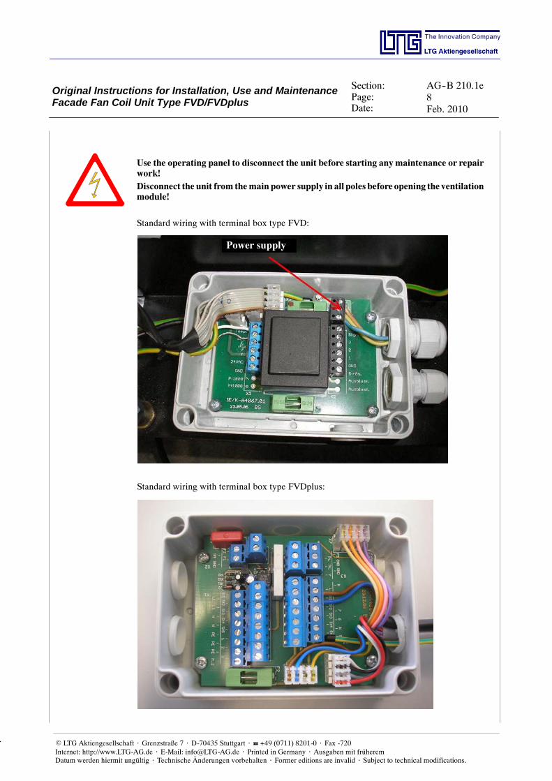
Use the operating panel to disconnect the unit before starting anymaintenance or repairwork!Disconnect the unit from themain power supply in all poles before opening the ventilationmodule!
Standard wiring with terminal box type FVD:
Power supply
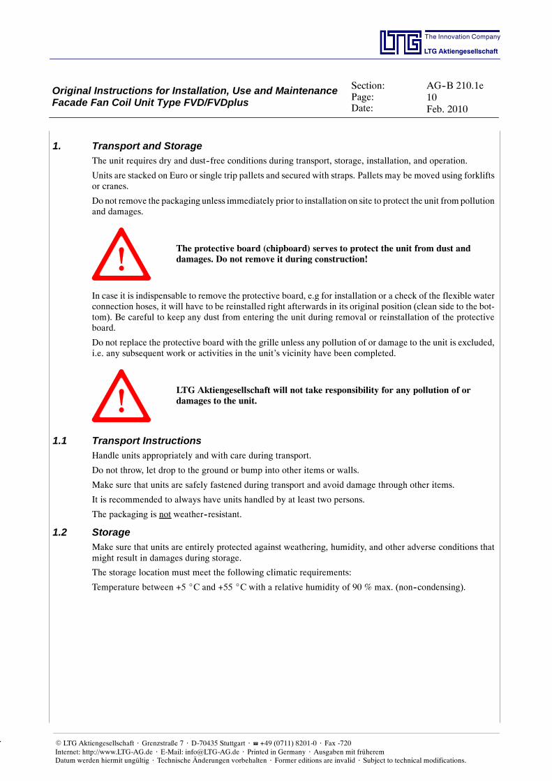
Standard wiring with terminal box type FVDplus:
Original Instructions for Installation, Use and MaintenanceFacade Fan Coil Unit Type FVD/FVDplus
Section:Page:Date:
AG--B 210.1e9Feb. 2010
The Innovation Company
LTG Aktiengesellschaft
E LTG Aktiengesellschaft ⋅ Grenzstraße 7 ⋅ D-70435 Stuttgart ⋅ +49 (0711) 8201-0 ⋅ Fax -720Internet: http://www.LTG-AG.de ⋅ E-Mail: [email protected] ⋅ Printed in Germany ⋅ Ausgaben mit früheremDatum werden hiermit ungültig ⋅ Technische Änderungen vorbehalten ⋅ Former editions are invalid ⋅ Subject to technical modifications.
Please observe any additional wiring diagrams for electrotechnical installations!
Depending on the unit version you may e.g. use the 3--pole repair connector shown belowto disconnect the unit (optional).
Original Instructions for Installation, Use and MaintenanceFacade Fan Coil Unit Type FVD/FVDplus
Section:Page:Date:
AG--B 210.1e10Feb. 2010
The Innovation Company
LTG Aktiengesellschaft
E LTG Aktiengesellschaft ⋅ Grenzstraße 7 ⋅ D-70435 Stuttgart ⋅ +49 (0711) 8201-0 ⋅ Fax -720Internet: http://www.LTG-AG.de ⋅ E-Mail: [email protected] ⋅ Printed in Germany ⋅ Ausgaben mit früheremDatum werden hiermit ungültig ⋅ Technische Änderungen vorbehalten ⋅ Former editions are invalid ⋅ Subject to technical modifications.
1. Transport and StorageThe unit requires dry and dust--free conditions during transport, storage, installation, and operation.
Units are stacked on Euro or single trip pallets and secured with straps. Pallets may be moved using forkliftsor cranes.
Do not remove the packaging unless immediately prior to installation on site to protect the unit from pollutionand damages.
The protective board (chipboard) serves to protect the unit from dust anddamages. Do not remove it during construction!
In case it is indispensable to remove the protective board, e.g for installation or a check of the flexible waterconnection hoses, it will have to be reinstalled right afterwards in its original position (clean side to the bot-tom). Be careful to keep any dust from entering the unit during removal or reinstallation of the protectiveboard.
Do not replace the protective board with the grille unless any pollution of or damage to the unit is excluded,i.e. any subsequent work or activities in the unit’s vicinity have been completed.
LTG Aktiengesellschaft will not take responsibility for any pollution of ordamages to the unit.
1.1 Transport InstructionsHandle units appropriately and with care during transport.
Do not throw, let drop to the ground or bump into other items or walls.
Make sure that units are safely fastened during transport and avoid damage through other items.
It is recommended to always have units handled by at least two persons.
The packaging is not weather--resistant.
1.2 StorageMake sure that units are entirely protected against weathering, humidity, and other adverse conditions thatmight result in damages during storage.
The storage location must meet the following climatic requirements:
Temperature between +5 _C and +55 _C with a relative humidity of 90 % max. (non--condensing).
Original Instructions for Installation, Use and MaintenanceFacade Fan Coil Unit Type FVD/FVDplus
Section:Page:Date:
AG--B 210.1e11Feb. 2010
The Innovation Company
LTG Aktiengesellschaft
E LTG Aktiengesellschaft ⋅ Grenzstraße 7 ⋅ D-70435 Stuttgart ⋅ +49 (0711) 8201-0 ⋅ Fax -720Internet: http://www.LTG-AG.de ⋅ E-Mail: [email protected] ⋅ Printed in Germany ⋅ Ausgaben mit früheremDatum werden hiermit ungültig ⋅ Technische Änderungen vorbehalten ⋅ Former editions are invalid ⋅ Subject to technical modifications.
2. Function
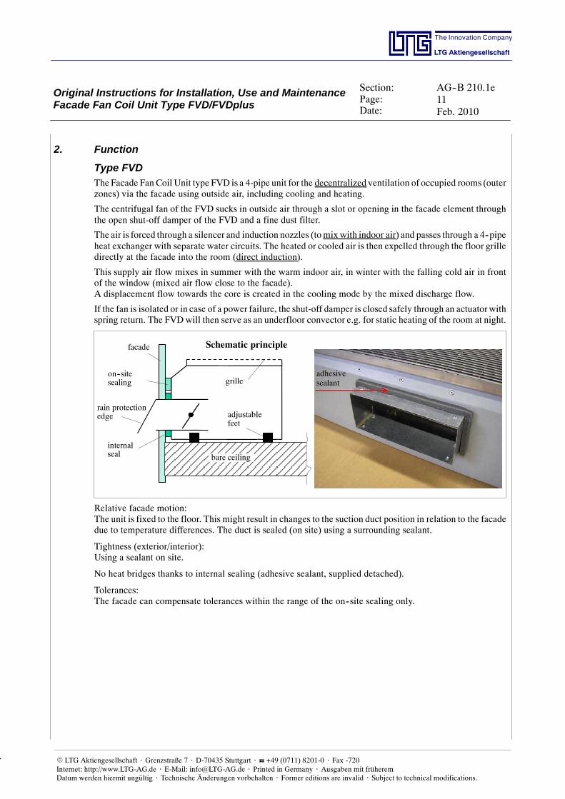
Type FVDThe Facade FanCoil Unit type FVD is a 4-pipe unit for the decentralized ventilation of occupied rooms (outerzones) via the facade using outside air, including cooling and heating.
The centrifugal fan of the FVD sucks in outside air through a slot or opening in the facade element throughthe open shut-off damper of the FVD and a fine dust filter.
The air is forced through a silencer and induction nozzles (tomix with indoor air) and passes through a 4--pipeheat exchanger with separate water circuits. The heated or cooled air is then expelled through the floor grilledirectly at the facade into the room (direct induction).
This supply air flow mixes in summer with the warm indoor air, in winter with the falling cold air in frontof the window (mixed air flow close to the facade).A displacement flow towards the core is created in the cooling mode by the mixed discharge flow.
If the fan is isolated or in case of a power failure, the shut-off damper is closed safely through an actuator withspring return. The FVDwill then serve as an underfloor convector e.g. for static heating of the room at night.
adhesivesealant
on--sitesealing
Schematic principlefacade
rain protectionedge
internalseal
grille
bare ceiling
adjustablefeet
Relative facade motion:The unit is fixed to the floor. This might result in changes to the suction duct position in relation to the facadedue to temperature differences. The duct is sealed (on site) using a surrounding sealant.
Tightness (exterior/interior):Using a sealant on site.
No heat bridges thanks to internal sealing (adhesive sealant, supplied detached).
Tolerances:The facade can compensate tolerances within the range of the on--site sealing only.
Original Instructions for Installation, Use and MaintenanceFacade Fan Coil Unit Type FVD/FVDplus
Section:Page:Date:
AG--B 210.1e12Feb. 2010
The Innovation Company
LTG Aktiengesellschaft
E LTG Aktiengesellschaft ⋅ Grenzstraße 7 ⋅ D-70435 Stuttgart ⋅ +49 (0711) 8201-0 ⋅ Fax -720Internet: http://www.LTG-AG.de ⋅ E-Mail: [email protected] ⋅ Printed in Germany ⋅ Ausgaben mit früheremDatum werden hiermit ungültig ⋅ Technische Änderungen vorbehalten ⋅ Former editions are invalid ⋅ Subject to technical modifications.
Type FVDplus
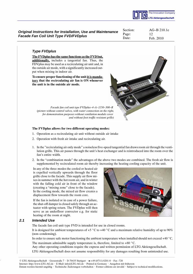
TheFVDplushas the same functions as the FVDbut,additionally, includes a tangential fan. Thus, theFDVplus may be used as a recirculating air unit and, inthe outside airmode,with a significantly increasedout-put when mixing in indoor air.
To ensure proper functioning of the unit it ismanda-tory that the recirculating air fan is ON wheneverthe unit is in the outside air mode.
Facade fan coil unit type FVDplus--4--A--1150--300--R(picture without control valves, with water connection on the right,
for demonstration purposes without ventilation module coverand without foot traffic resistant grille)
The FVDplus allows for two different operating modes:
1. Operation as a recirculating air unit without outside air intake
2. Operation with fresh air intake and recirculating air.
1. In the ”recirculating air onlymode” a noiseless five-speed tangential fan draws room air through the venti-lation grille. This air passes through the unit’s heat exchanger and is reintroduced into the room over thefan’s entire width.
2. In the “combination mode” the advantages of the above two modes are combined. The fresh air flow issupplemented by recirculated room air thereby increasing the heating cooling capacity of the unit.
In any of the three modes the cooled or heated airis expelled vertically upwards through the floorgrille close to the facade. This supply air flowmi-xes in summer with the hot room air, and inwinterwith the falling cold air in front of the window(creating a “mixing zone” close to the facade).In the cooling mode, the mixed air flow creates adisplacement flow towards the room core.
If the fan is isolated or in case of a power failure,the shut-off damper is closed safely through an ac-tuator with spring return. The FVDplus will thenserve as an underfloor convector e.g. for staticheating of the room at night.
2.1 Intended UseThe facade fan coil unit type FVD is intended for use in closed rooms.
It is designed for ambient temperatures of +5 _C to +40 _C and a maximum relative humidity of up to 90%(non--condensing).
In order to ensure safe motor functioning the ambient temperature when installed should not exceed +40 _C.
The maximum admissible supply temperature is, therefore, limited to +80 _C.Any other operating conditions require the express and written permission of LTG Aktiengesellschaft.
LTG Aktiengesellschaft does not assume responsibility for any damages resulting from unintended use.
Original Instructions for Installation, Use and MaintenanceFacade Fan Coil Unit Type FVD/FVDplus
Section:Page:Date:
AG--B 210.1e13Feb. 2010
The Innovation Company
LTG Aktiengesellschaft
E LTG Aktiengesellschaft ⋅ Grenzstraße 7 ⋅ D-70435 Stuttgart ⋅ +49 (0711) 8201-0 ⋅ Fax -720Internet: http://www.LTG-AG.de ⋅ E-Mail: [email protected] ⋅ Printed in Germany ⋅ Ausgaben mit früheremDatum werden hiermit ungültig ⋅ Technische Änderungen vorbehalten ⋅ Former editions are invalid ⋅ Subject to technical modifications.
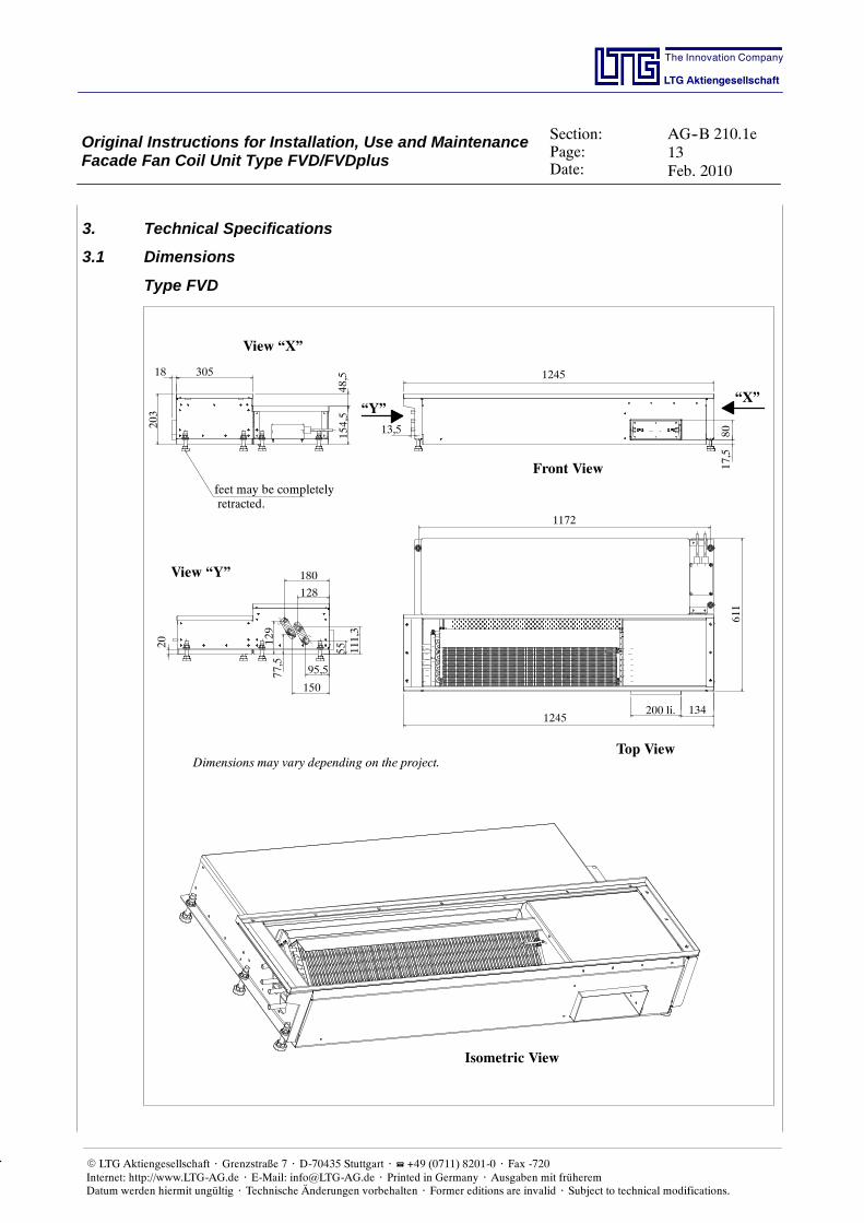
3. Technical Specifications
3.1 Dimensions
Type FVD
Top View
Front View
View “X”
“X”“Y”
View “Y”
1245
1245
200 li. 134
1172
150
611
13,5
17,5
80
180
95,5
128
55 111,3
154,5
77,5
129
305
48,5
203
20
18
feet may be completelyretracted.
Isometric View
Dimensions may vary depending on the project.
Original Instructions for Installation, Use and MaintenanceFacade Fan Coil Unit Type FVD/FVDplus
Section:Page:Date:
AG--B 210.1e14Feb. 2010
The Innovation Company
LTG Aktiengesellschaft
E LTG Aktiengesellschaft ⋅ Grenzstraße 7 ⋅ D-70435 Stuttgart ⋅ +49 (0711) 8201-0 ⋅ Fax -720Internet: http://www.LTG-AG.de ⋅ E-Mail: [email protected] ⋅ Printed in Germany ⋅ Ausgaben mit früheremDatum werden hiermit ungültig ⋅ Technische Änderungen vorbehalten ⋅ Former editions are invalid ⋅ Subject to technical modifications.
Type FVDplus
Isometric View
Unit dimensions may vary to match the specific project
Top View
Front View
Lateral View
155
1150
200
1042108
305611
18611
48
203
61
80
Feet may be com-pletely retracted
Water connectionsto match the specific project
Original Instructions for Installation, Use and MaintenanceFacade Fan Coil Unit Type FVD/FVDplus
Section:Page:Date:
AG--B 210.1e15Feb. 2010
The Innovation Company
LTG Aktiengesellschaft
E LTG Aktiengesellschaft ⋅ Grenzstraße 7 ⋅ D-70435 Stuttgart ⋅ +49 (0711) 8201-0 ⋅ Fax -720Internet: http://www.LTG-AG.de ⋅ E-Mail: [email protected] ⋅ Printed in Germany ⋅ Ausgaben mit früheremDatum werden hiermit ungültig ⋅ Technische Änderungen vorbehalten ⋅ Former editions are invalid ⋅ Subject to technical modifications.
3.2 Electrical Data
Connect the unit to a residual current device (RCD).
Supply voltage 230 V AC
Required back--up fuse 10 A
Power consumption max. about 100 VA
cos. on average about 0.7 (depending on working point)
Charging current at making operationAs soon as the fan is connected to the main power supplyit is provided with a short--term charging current whichmay be up to 6.5 A but for 1 ms only.
Switching voltage of the fan speeds Rectified mains potential
Fan speed activation (outside air)Fan speed integration must be realized via floating con-tacts
Activation of the recirculating air speed Supply voltage is applied to 3 of 5 speeds
Max. switching currents of the fan speeds 1 mA
Valve power consumption (optional) see separate data sheet
Valve supply voltage (optional) see separate data sheet
3.3 WeightFVD--A--1200--200 approx. 40 kg
FVD--A--1200--300 approx. 45 kg
FVDplus approx. 51 kg
Original Instructions for Installation, Use and MaintenanceFacade Fan Coil Unit Type FVD/FVDplus
Section:Page:Date:
AG--B 210.1e16Feb. 2010
The Innovation Company
LTG Aktiengesellschaft
E LTG Aktiengesellschaft ⋅ Grenzstraße 7 ⋅ D-70435 Stuttgart ⋅ +49 (0711) 8201-0 ⋅ Fax -720Internet: http://www.LTG-AG.de ⋅ E-Mail: [email protected] ⋅ Printed in Germany ⋅ Ausgaben mit früheremDatum werden hiermit ungültig ⋅ Technische Änderungen vorbehalten ⋅ Former editions are invalid ⋅ Subject to technical modifications.
3.4 Caloric Output DataCaloric output data were determined at a test stand in the LTG test lab.Data are valid if the following applies:- unit at operating temperature, steady--state condition- steady--state condition during measurements- no condensation at the heat exchanger in the cooling mode- water without additives (drinking water quality)*- water supply temperatures from 12 _C to 16 _C in the coolingmode and 50 _C -- 60 _C in the heatingmode.
Parameters used:- specific heat capacity of the water 4186 J/(kgK)- specific heat capacity of the air 1004 J/(kgK)- air density 1.2 kg/m3
To ensure easy transferability, the specific caloric outputs -- i.e. the absolute caloric outputs in relation to thetemperature difference between water intake and induction air before entering the heat exchanger -- are givenwith varying fan speeds.
The outputs given in the chart do apply with specific nominal flow rates only. These are stated for each typeand size.
The correction charts give a graphic illustration of how outputs change with other flow rates compared to no-minal flow rate output.
Flow rates have been determined through calculation and may vary by about 10%.
* Addition of ethylene glycol to lower the freezing point:
To lower the freezing point, coolingwater is often added some ethylene glycol. The lower specific thermalcapacity of the mixture reduces the unit’s cooling capacity.
3.5 Acoustic DataAcoustic data have been determined in a reverberation chamber in the LTG test lab.The technical data sheet contain the A weighted sound pressure levels LA18 for different fan speeds.
Sound pressure levels apply to a room absorption surface of 18 m2 which equals a room absorption of about6 dB(A). Thus, sound power levels may easily be calculated.
LWA = LA18 + 6 dB(A)
The data given apply to one unit, i.e. one room axle. If more than one unit is installed in the same room, thesound pressure level will rise accordingly.
Increase in sound level with several sound sources of the same type:
Number of sound sources of the same type 1 2 3 4
Sound level increase [dB] 3 5 6
Measuring accuracy is 10%.
3.6 Hydraulic DataHeat exchangers are approved for an operating pressure of 10 bar max. (test pressure 16 bar).Pressures exceeding 10 bar require the express permission of LTG.
Water--side pressure losses have been measured directly at the heat exchanger connections. Further resi-stances will have to be added.
Measuring accuracy is 10%.
Original Instructions for Installation, Use and MaintenanceFacade Fan Coil Unit Type FVD/FVDplus
Section:Page:Date:
AG--B 210.1e17Feb. 2010
The Innovation Company
LTG Aktiengesellschaft
E LTG Aktiengesellschaft ⋅ Grenzstraße 7 ⋅ D-70435 Stuttgart ⋅ +49 (0711) 8201-0 ⋅ Fax -720Internet: http://www.LTG-AG.de ⋅ E-Mail: [email protected] ⋅ Printed in Germany ⋅ Ausgaben mit früheremDatum werden hiermit ungültig ⋅ Technische Änderungen vorbehalten ⋅ Former editions are invalid ⋅ Subject to technical modifications.
4. Installation
4.1 Installation InstructionsThe unit is usually supplied as described in the following:
- Unit with completely retracted feet and slightly fixed counternuts and a protective board (chipboard) inser-ted instead of the foot traffic resistant grille.
- Connecting cords coiled up on the unit (if included in the delivery)
- Required installation material and parts, if any, such as rivets, screws, bolts, junction sheets, fixing links,air duct are included in the delivery.
The following points must always be observed when installing the unit:
- Do not remove the protective board (chipboard) unless to execute the water andelectrical connections. Reinstall the protective board until the grille is inserted intothe unit to avoid damages to and pollution of the unit.
- Anywork in connectionwith the electrical equipment and thewater connectionsis to be performed by skilled and trained staff only.
- When installing the unit on site an insulating strip is to be used between the unit andthe facade and between the unit and the floor boards.
- The counternuts of the supporting feet are to be fastened using a 3 Nm torque.
- When fixing the units to the floor using the fastening brackets included in the deli-very, a sound insulation is to be installed on the bottom side of the brackets to avoidsound transmission.
- Before inserting the outlet grille the protective foil on the valve chamber’s sheetsteel cover is to be removed.
Exact adjustment of the unit is achieved via heightadjustable feet on the unit’s outside.
The valve chamber for control valve connection islocated on the side opposite to the suction opening.
Tube passages for water supply are also located onthe side opposite to the suction opening, in the fa-cade module’s rear panel.
The unit’s upper edge, which is identical to that ofthe foot traffic resistant ventilation grille, is to beinstalled flush with the prefabricated floor.
In the blower module area floor panelsmay be laidon top of the blower module cover using insulatingspacers.
Facade
Facade Fan Coil Unit Type FVD – Facade installationwith laid floor panels and floor covering
The compact design with unit depths of 511 mm (grille width 200 mm) or 611 mm (grille with 300 mm,FVDplus grille with 300 mm only) allows for an installation of the unit between floor supports.
Original Instructions for Installation, Use and MaintenanceFacade Fan Coil Unit Type FVD/FVDplus
Section:Page:Date:
AG--B 210.1e18Feb. 2010
The Innovation Company
LTG Aktiengesellschaft
E LTG Aktiengesellschaft ⋅ Grenzstraße 7 ⋅ D-70435 Stuttgart ⋅ +49 (0711) 8201-0 ⋅ Fax -720Internet: http://www.LTG-AG.de ⋅ E-Mail: [email protected] ⋅ Printed in Germany ⋅ Ausgaben mit früheremDatum werden hiermit ungültig ⋅ Technische Änderungen vorbehalten ⋅ Former editions are invalid ⋅ Subject to technical modifications.
4.2 Unit InstallationPlease observe the following when installing the unit:
- Supporting feet must be preadjusted to ensure that the unit’s own weight is carried by the supporting feetand not by the outside air socket.
- Tighten the supporting feet’s lock nuts observing a torque of3 Nm.
- Secure the unit against horizontal shifting, e.g. by using thefixing links available as accessories.
- Do not fix other components to the unit unless with LTGAk-tiengesellschaft’s express permission and prior release.
- Take care to avoid any direct contact between the unit and theraw floor except by the supporting feet to eliminate sound andfoot traffic noise transmission.
- Take care to avoid any direct contact between the unit and thefacade and suction duct to avoid sound transmission, exceptvia seals designed for this purpose (VDE 6022, hydrophobicand closed pored).
Laying the Floor
- When laying the floor take special care to avoid any direct contact between the floor boards and the unit, i.e.do not place floor boards directly on the unit and avoid their touching laterally. Ensure the use of a soundinsulation element in between or use an appropriate sealant (see above) between the unit and the false floor’sboards.
Original Instructions for Installation, Use and MaintenanceFacade Fan Coil Unit Type FVD/FVDplus
Section:Page:Date:
AG--B 210.1e19Feb. 2010
The Innovation Company
LTG Aktiengesellschaft
E LTG Aktiengesellschaft ⋅ Grenzstraße 7 ⋅ D-70435 Stuttgart ⋅ +49 (0711) 8201-0 ⋅ Fax -720Internet: http://www.LTG-AG.de ⋅ E-Mail: [email protected] ⋅ Printed in Germany ⋅ Ausgaben mit früheremDatum werden hiermit ungültig ⋅ Technische Änderungen vorbehalten ⋅ Former editions are invalid ⋅ Subject to technical modifications.
4.3 Facade Outside Air ConnectionThe unit is standard provided with an outside air connection, 202.25 mm wide and 81.5 mm high (may varydepending on project). If an extension of this outside air duct is considered it will have to be properly insulatedon site to keep fresh air from cooling the outside air duct to a degree that would result in condensation on thesurface or massive heating energy loss.
Internat fixing dimensions must be at least 200 mm in width and 80mm in height. Keep the sealing or insula-tion from protruding into the opening space of the suction since this might result in disturbing the outside airdamper when opening.
When installing the unit take special care:
- to ensure that the outside air duct and the outside air connection are clean
- to provide proper sealing to the outside air connection using a suitable hydrophobic and closed pored sealantmeeting VDI 6022 requirements.
- Facade connection must be designed in a way to ensure that the speed will not exceed 2 m/s over the entireair intake section if the outside air flow rate is 120 m3/h.
Before putting the unit into operation make sure that the flow path of the outside air to the unit is clean, mee-ting pertinent sanitation requirements, to avoid immediate contamination of the unit, the filter, and the roomto be ventilated.
Ensure that the facade geometry will keep water from entering the outsideair connection opening at any time and under any circumstances.
Original Instructions for Installation, Use and MaintenanceFacade Fan Coil Unit Type FVD/FVDplus
Section:Page:Date:
AG--B 210.1e20Feb. 2010
The Innovation Company
LTG Aktiengesellschaft
E LTG Aktiengesellschaft ⋅ Grenzstraße 7 ⋅ D-70435 Stuttgart ⋅ +49 (0711) 8201-0 ⋅ Fax -720Internet: http://www.LTG-AG.de ⋅ E-Mail: [email protected] ⋅ Printed in Germany ⋅ Ausgaben mit früheremDatum werden hiermit ungültig ⋅ Technische Änderungen vorbehalten ⋅ Former editions are invalid ⋅ Subject to technical modifications.
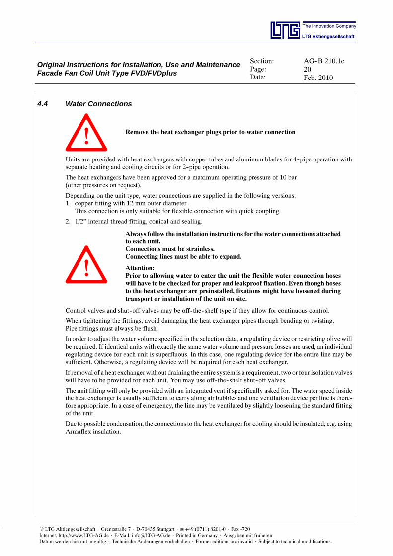
4.4 Water Connections
Remove the heat exchanger plugs prior to water connection
Units are provided with heat exchangers with copper tubes and aluminum blades for 4--pipe operation withseparate heating and cooling circuits or for 2--pipe operation.
The heat exchangers have been approved for a maximum operating pressure of 10 bar(other pressures on request).
Depending on the unit type, water connections are supplied in the following versions:1. copper fitting with 12 mm outer diameter.
This connection is only suitable for flexible connection with quick coupling.
2. 1/2” internal thread fitting, conical and sealing.
Always follow the installation instructions for the water connections attachedto each unit.Connections must be strainless.Connecting lines must be able to expand.
Attention:Prior to allowing water to enter the unit the flexible water connection hoseswill have to be checked for proper and leakproof fixation. Even though hosesto the heat exchanger are preinstalled, fixations might have loosened duringtransport or installation of the unit on site.
Control valves and shut--off valves may be off--the--shelf type if they allow for continuous control.
When tightening the fittings, avoid damaging the heat exchanger pipes through bending or twisting.Pipe fittings must always be flush.
In order to adjust the water volume specified in the selection data, a regulating device or restricting olive willbe required. If identical units with exactly the same water volume and pressure losses are used, an individualregulating device for each unit is superfluous. In this case, one regulating device for the entire line may besufficient. Otherwise, a regulating device will be required for each heat exchanger.
If removal of a heat exchangerwithout draining the entire system is a requirement, two or four isolation valveswill have to be provided for each unit. You may use off--the--shelf shut--off valves.
The unit fitting will only be provided with an integrated vent if specifically asked for. The water speed insidethe heat exchanger is usually sufficient to carry along air bubbles and one ventilation device per line is there-fore appropriate. In a case of emergency, the line may be ventilated by slightly loosening the standard fittingof the unit.
Due to possible condensation, the connections to the heat exchanger for cooling should be insulated, e.g. usingArmaflex insulation.
Original Instructions for Installation, Use and MaintenanceFacade Fan Coil Unit Type FVD/FVDplus
Section:Page:Date:
AG--B 210.1e21Feb. 2010
The Innovation Company
LTG Aktiengesellschaft
E LTG Aktiengesellschaft ⋅ Grenzstraße 7 ⋅ D-70435 Stuttgart ⋅ +49 (0711) 8201-0 ⋅ Fax -720Internet: http://www.LTG-AG.de ⋅ E-Mail: [email protected] ⋅ Printed in Germany ⋅ Ausgaben mit früheremDatum werden hiermit ungültig ⋅ Technische Änderungen vorbehalten ⋅ Former editions are invalid ⋅ Subject to technical modifications.
Connection type FVD
cooling waterreturn
heating waterreturn
antifreeze sensor
venting
305
cooling waterinlet
heating waterinlet
fresh airintake
Connection type FVDplus
heating water return
antifreeze sensor
308
Diffused airtemperature sensor
heating water inlet
cooling water return
cooling water inlet
Original Instructions for Installation, Use and MaintenanceFacade Fan Coil Unit Type FVD/FVDplus
Section:Page:Date:
AG--B 210.1e22Feb. 2010
The Innovation Company
LTG Aktiengesellschaft
E LTG Aktiengesellschaft ⋅ Grenzstraße 7 ⋅ D-70435 Stuttgart ⋅ +49 (0711) 8201-0 ⋅ Fax -720Internet: http://www.LTG-AG.de ⋅ E-Mail: [email protected] ⋅ Printed in Germany ⋅ Ausgaben mit früheremDatum werden hiermit ungültig ⋅ Technische Änderungen vorbehalten ⋅ Former editions are invalid ⋅ Subject to technical modifications.
The water connection side is to be specified when ordering the unit. Some units offer a possibility to stillchange the side during installation by removing 4 bolts.
Example for water connection using flexible hose(Quick coupling connection to heat exchangers)
Hose without insulation. For insulated hoses, dimensions will change accordingly(10 mm Armaflex insulation).
Hose for connection to heat exchanger with smooth tube end diameter 12 mm,connection types: quick coupling, quick coupling with venting
Different hose connections, thread diameter acc. to customer requirements or standard 1/2”
min.150
min.35
min.35
min.R50
ca.100ca.200
min.150
min.35
min.35
min.R50
ca.100
ca.200
Ø17
DN12
Ø17
DN12
Example for water connectionusing transition - LTG description VSG 10/ 2 EH (venting) -,straight-way valve and flexible hose
min.35
min.35
min.R50
Ø15
DN10
Hose without insulation. For insulated hoses, dimensions will change accordingly.
Hose for connection to angle or straight-way valve,connection type: AGK, external thread, tapered 1/2”
Different hose connections, thread diameter acc. to customer requirements or standard 1/2”
Original Instructions for Installation, Use and MaintenanceFacade Fan Coil Unit Type FVD/FVDplus
Section:Page:Date:
AG--B 210.1e23Feb. 2010
The Innovation Company
LTG Aktiengesellschaft
E LTG Aktiengesellschaft ⋅ Grenzstraße 7 ⋅ D-70435 Stuttgart ⋅ +49 (0711) 8201-0 ⋅ Fax -720Internet: http://www.LTG-AG.de ⋅ E-Mail: [email protected] ⋅ Printed in Germany ⋅ Ausgaben mit früheremDatum werden hiermit ungültig ⋅ Technische Änderungen vorbehalten ⋅ Former editions are invalid ⋅ Subject to technical modifications.
Example for water connection using valve and flexible hose(straight and 90_ variant)
Hose without insulation. For insulated hoses, dimensions will change accordingly.(10 mm Armaflex insulation
Hose for connection to straight-way valve,Connection type AGK, external thread, tapered 1/2”
Different hose connections, thread diameter acc. to customer requirements or standard 1/2”
Connection for direct screwing into the heat exchanger in case of angle connection,Connection type: double nipple 1/2”--1/2”; UFD hose connection, 1/2” flat seal union nut
Example for water connection for direct screwing into the heat exchanger
Hose without insulation. For insulated hoses, dimensions will change accordingly.
Connection for direct screwing into the heat exchangerConnection type: AGK, external thread, tapered 1/2”
Different hose connections, thread diameter acc. to customer requirements or standard 1/2”
min.150
min.35
min. R 50Ø17
DN12
min.150
min.35
min. R 50
Ø17
DN12
Original Instructions for Installation, Use and MaintenanceFacade Fan Coil Unit Type FVD/FVDplus
Section:Page:Date:
AG--B 210.1e24Feb. 2010
The Innovation Company
LTG Aktiengesellschaft
E LTG Aktiengesellschaft ⋅ Grenzstraße 7 ⋅ D-70435 Stuttgart ⋅ +49 (0711) 8201-0 ⋅ Fax -720Internet: http://www.LTG-AG.de ⋅ E-Mail: [email protected] ⋅ Printed in Germany ⋅ Ausgaben mit früheremDatum werden hiermit ungültig ⋅ Technische Änderungen vorbehalten ⋅ Former editions are invalid ⋅ Subject to technical modifications.
4.4.1 Instructions for Installation of Water Connections Using Flexible Hoses
Warranty will only apply if the following instructions are observed and if in-stallation is performed in compliance with DIN--EN regulations.In particular, corrosive, electrochemical, and bacteriological charges are tobe excluded taking appropriate preventive measures.
- Pressure and exposition to heat may re-sult in slight elongation of the hose.Therefore, newly placed hoses must con-sider such potential elongation.
- Do not fall below the admissible bendingradius Rmin (chart), neither during trans-port, nor during installation or when in-stalled.If it should turn out impossible to keepthe admissible bending radius, choose adifferent installation type.
- For minimum length see chart below.If the hose is being placed by bending it,check whether there is sufficient hoselength to allow for an open bow in orderto avoid kinking and destruction of thehose at the connecting points.
- Absolutely avoid distorting or kinkingthe flexible connection.
- Do not subject the hose to any tensile orpressure loads applied from outside, nei-ther during installation nor operation.
- Do not retighten rigid connections (outerthread) after fixing the second connec-tion since this might result in distortionof or damage to the hose.
- In general, tightness of the connection(hose/connector) is the responsibility ofthe technician performing the installa-tion.
- Any sealing material included in the deli-very is to be verified by the technicianfor its suitability since the hose manufac-turer has no information about the mate-rial or geometry of the connections.
correct incorrect
Original Instructions for Installation, Use and MaintenanceFacade Fan Coil Unit Type FVD/FVDplus
Section:Page:Date:
AG--B 210.1e25Feb. 2010
The Innovation Company
LTG Aktiengesellschaft
E LTG Aktiengesellschaft ⋅ Grenzstraße 7 ⋅ D-70435 Stuttgart ⋅ +49 (0711) 8201-0 ⋅ Fax -720Internet: http://www.LTG-AG.de ⋅ E-Mail: [email protected] ⋅ Printed in Germany ⋅ Ausgaben mit früheremDatum werden hiermit ungültig ⋅ Technische Änderungen vorbehalten ⋅ Former editions are invalid ⋅ Subject to technical modifications.
Lmin
RminD ext.
Armoured hose Oxystop up to +70 _C (diffusion inhibiting, marked through weaved--in blue strip)Armoured hose EPDM up to +93 _C (vapour permeable, not marked)
NDhose
DA PN[bar]
Rmin Lmin Lmin = 90_
Lmin = 180_
Lmin = 360_
06/08 12 15 27 60 140 180 260
10 14 15 40 60 190 250 260
12 18 15 60 80 260 360 550
15 22 12 70 95 300 420 640
19 27 10 80 100 350 480 730
25 34 10 100 125 430 590 900
32 44 10 160 140 650 900 1400
40 54 6 180 160 750 1030 1600
50 64 6 230 210 940 1300 2020
Armoured hose Oxyblock* at + 30 _C / 10 bar at + 50 _C (vapour impermeable, marked through weaved--in blue--white strip)
NDhose
DA PN[bar]
Rmin Lmin Lmin = 90_
Lmin = 180_
Lmin = 360_
08 13,5 16 * 110 100 310 490 830
10 16 16 * 130 100 380 580 990
12 17 16 * 150 100 450 680 1150
Original Instructions for Installation, Use and MaintenanceFacade Fan Coil Unit Type FVD/FVDplus
Section:Page:Date:
AG--B 210.1e26Feb. 2010
The Innovation Company
LTG Aktiengesellschaft
E LTG Aktiengesellschaft ⋅ Grenzstraße 7 ⋅ D-70435 Stuttgart ⋅ +49 (0711) 8201-0 ⋅ Fax -720Internet: http://www.LTG-AG.de ⋅ E-Mail: [email protected] ⋅ Printed in Germany ⋅ Ausgaben mit früheremDatum werden hiermit ungültig ⋅ Technische Änderungen vorbehalten ⋅ Former editions are invalid ⋅ Subject to technical modifications.
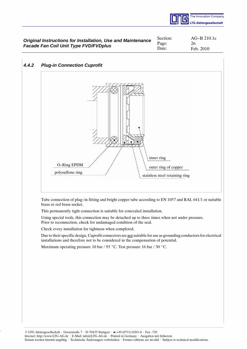
4.4.2 Plug-in Connection Cuprofit
O--Ring EPDM
polysulfone ring
inner ring
outer ring of copper
stainless steel retaining ring
Tube connection of plug--in fitting and bright copper tube according to EN 1057 and RAL 641/1 or suitablebrass or red brass socket.
This permanently tight connection is suitable for concealed installation.
Using special tools, this connection may be detached up to three times when not under pressure.Prior to reconnection, check for undamaged condition of the seal.
Check every installation for tightness when completed.
Due to their specific design, Cuprofit connectors are not suitable for use as grounding conductors for electricalinstallations and therefore not to be considered in the compensation of potential.
Maximum operating pressure 10 bar / 93 _C. Test pressure 16 bar / 30 _C.
Original Instructions for Installation, Use and MaintenanceFacade Fan Coil Unit Type FVD/FVDplus
Section:Page:Date:
AG--B 210.1e27Feb. 2010
The Innovation Company
LTG Aktiengesellschaft
E LTG Aktiengesellschaft ⋅ Grenzstraße 7 ⋅ D-70435 Stuttgart ⋅ +49 (0711) 8201-0 ⋅ Fax -720Internet: http://www.LTG-AG.de ⋅ E-Mail: [email protected] ⋅ Printed in Germany ⋅ Ausgaben mit früheremDatum werden hiermit ungültig ⋅ Technische Änderungen vorbehalten ⋅ Former editions are invalid ⋅ Subject to technical modifications.
4.5 Condensate ConnectionCondensate formation occurswhen the coldwater supply temperature is below the ambient air dewpoint tem-perature. Neither LTG induction units nor LTG fan coil units or LTF facade fan coil units have been designedfor an operation with steady condensate formation which is why special care must be taken when setting thewater inlet temperature not to fall below the dewpoint temperature. If necessary, provide a continuous controlof the water temperature based on outside air humidity.
A central cold water control and weather related cold water supply temperature raise is recommended sinceopening the windows might result in outside air with a high humidity entering the room and the temperaturedropping below the air’s dew point.
4.6 Electrical Connections
Connect the unit to a residual current device (RCD).
Electrical connection is performed via a terminal box mounted to the unit, type of protection IP 66. Here,supply lines are connected on site.
Available are 3 outside air flow rates which may be triggered directly via a control line. This control line hasan outside air flow--dependent voltage of up to mains potential.Activation in groups of up to 3 units is possible (using the same phase).
An error message may be applied to the terminal box. The message will be displayed in case one of the follo-wing conditions occurs:
- the fan doesn’t move despite of load applied
- antifreeze is active (heat exchanger temperature < 10 _C)
- set flow rate is not achieved within 120 seconds.
Connection of a diffused air temperature sensor is optional.
Original Instructions for Installation, Use and MaintenanceFacade Fan Coil Unit Type FVD/FVDplus
Section:Page:Date:
AG--B 210.1e28Feb. 2010
The Innovation Company
LTG Aktiengesellschaft
E LTG Aktiengesellschaft ⋅ Grenzstraße 7 ⋅ D-70435 Stuttgart ⋅ +49 (0711) 8201-0 ⋅ Fax -720Internet: http://www.LTG-AG.de ⋅ E-Mail: [email protected] ⋅ Printed in Germany ⋅ Ausgaben mit früheremDatum werden hiermit ungültig ⋅ Technische Änderungen vorbehalten ⋅ Former editions are invalid ⋅ Subject to technical modifications.
FVD wiring diagram
Power supply conn. 230 VLine: 3 x 0,75 mm2
Facade fan coil unit terminal box On--site wiring
Outside air flow ratesI -- IIILine: 4 x 0,75 mm2
Fan error messageLine: 2 x 0,5 mm2
220/24 V, 6,0 VAF1 = 32 mA, trF2 = 1,0 A, tr
LPEN
Sign321
Störm
Mains
Speeds
Error
Temp
U5Yμ
PENNL
--2PartyDay
Nighttemp--1
PWMTacho
5321
Antifreeze
Belimo
X5
X6
X7
F1
F2
FVDplus wiring diagram
Attention!Feedback voltage
230 V
3--step--switchOutside air fan
230 V
3--step--switchRecirculating air fan
230 V
Supply230 VPE N L
1
2
3
4
5
6
7
8
1
2
X1._
M_2
PE
PE
PE
N
N
L1
L1
Gnd
Error
X2._
X1’._
3
2
1
St. 5
St. 4
St. 3
St. 2
St. 1
Diffus.
Diffus.
X2’._
Attention! Do not connect the outside air fanand the recirculating air fan in parallel!
Original Instructions for Installation, Use and MaintenanceFacade Fan Coil Unit Type FVD/FVDplus
Section:Page:Date:
AG--B 210.1e29Feb. 2010
The Innovation Company
LTG Aktiengesellschaft
E LTG Aktiengesellschaft ⋅ Grenzstraße 7 ⋅ D-70435 Stuttgart ⋅ +49 (0711) 8201-0 ⋅ Fax -720Internet: http://www.LTG-AG.de ⋅ E-Mail: [email protected] ⋅ Printed in Germany ⋅ Ausgaben mit früheremDatum werden hiermit ungültig ⋅ Technische Änderungen vorbehalten ⋅ Former editions are invalid ⋅ Subject to technical modifications.
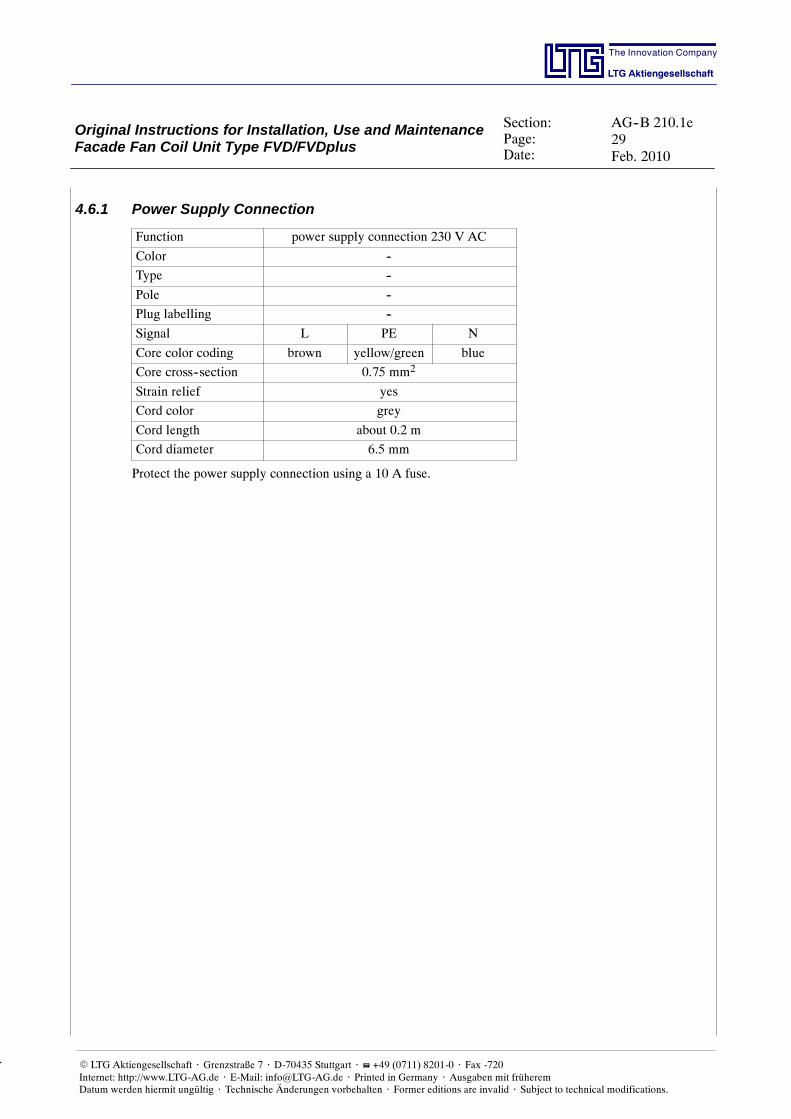
4.6.1 Power Supply Connection
Function power supply connection 230 V AC
Color --
Type --
Pole --
Plug labelling --
Signal L PE N
Core color coding brown yellow/green blue
Core cross--section 0.75 mm2
Strain relief yes
Cord color grey
Cord length about 0.2 m
Cord diameter 6.5 mm
Protect the power supply connection using a 10 A fuse.
Original Instructions for Installation, Use and MaintenanceFacade Fan Coil Unit Type FVD/FVDplus
Section:Page:Date:
AG--B 210.1e30Feb. 2010
The Innovation Company
LTG Aktiengesellschaft
E LTG Aktiengesellschaft ⋅ Grenzstraße 7 ⋅ D-70435 Stuttgart ⋅ +49 (0711) 8201-0 ⋅ Fax -720Internet: http://www.LTG-AG.de ⋅ E-Mail: [email protected] ⋅ Printed in Germany ⋅ Ausgaben mit früheremDatum werden hiermit ungültig ⋅ Technische Änderungen vorbehalten ⋅ Former editions are invalid ⋅ Subject to technical modifications.
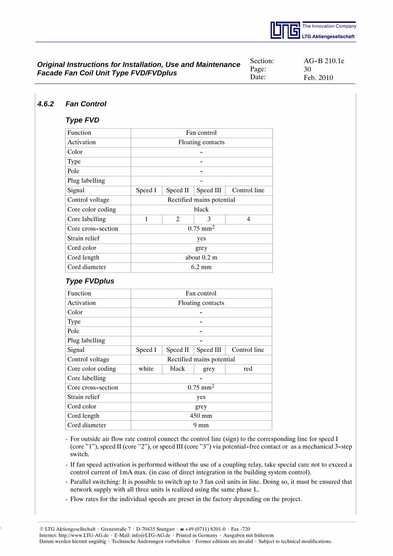
4.6.2 Fan Control
Type FVD
Function Fan control
Activation Floating contacts
Color --
Type --
Pole --
Plug labelling --
Signal Speed I Speed II Speed III Control line
Control voltage Rectified mains potential
Core color coding black
Core labelling 1 2 3 4
Core cross--section 0.75 mm2
Strain relief yes
Cord color grey
Cord length about 0.2 m
Cord diameter 6.2 mm
Type FVDplus
Function Fan control
Activation Floating contacts
Color --
Type --
Pole --
Plug labelling --
Signal Speed I Speed II Speed III Control line
Control voltage Rectified mains potential
Core color coding white black grey red
Core labelling --
Core cross--section 0.75 mm2
Strain relief yes
Cord color grey
Cord length 450 mm
Cord diameter 9 mm
- For outside air flow rate control connect the control line (sign) to the corresponding line for speed I(core ”1”), speed II (core ”2”), or speed III (core ”3”) via potential--free contact or as a mechanical 3--stepswitch.
- If fan speed activation is performed without the use of a coupling relay, take special care not to exceed acontrol current of 1mA max. (in case of direct integration in the building system control).
- Parallel switching: It is possible to switch up to 3 fan coil units in line. Doing so, it must be ensured thatnetwork supply with all three units is realized using the same phase L.
- Flow rates for the individual speeds are preset in the factory depending on the project.
Original Instructions for Installation, Use and MaintenanceFacade Fan Coil Unit Type FVD/FVDplus
Section:Page:Date:
AG--B 210.1e31Feb. 2010
The Innovation Company
LTG Aktiengesellschaft
E LTG Aktiengesellschaft ⋅ Grenzstraße 7 ⋅ D-70435 Stuttgart ⋅ +49 (0711) 8201-0 ⋅ Fax -720Internet: http://www.LTG-AG.de ⋅ E-Mail: [email protected] ⋅ Printed in Germany ⋅ Ausgaben mit früheremDatum werden hiermit ungültig ⋅ Technische Änderungen vorbehalten ⋅ Former editions are invalid ⋅ Subject to technical modifications.
4.6.3 Fan Error Message
Type FVD
Function Fan error messageThe brown core is applied with avoltage, 15 V DC higher compa-red to the white core,- if the fan does not move des-pite of applied current andswitched speed level or opera-tingmode, e.g. when themotoris broken or the impeller isblocked. A maximum currentof 10 mA may be applied;
- if the antifreeze is activated;
- if the nominal flow rate is notachieved within 120 s.
Color --
Type --
Pole --
Plug labelling --
Signal15 V DC10 mA 0 V
Core color coding brown white
Core cross--section 0.5 mm2
Strain relief yes
Cord color grey
Cord lenth ca. 0.2 m
Cord diameter 4.7 mm
Type FVDplus
Function Fan error messageThe brown core is applied with avoltage, 15 V DC higher compa-red to the white core,- if the fan does not move des-pite of applied current andswitched speed level or opera-tingmode, e.g. when themotoris broken or the impeller isblocked. A maximum currentof 10 mA may be applied;
- if the antifreeze is activated;
- if the nominal flow rate is notachieved within 120 s.
Color --
Type --
Pole --
Plug labelling --
Signal15 V DC10 mA 0 V
Core color coding lilac orange
Core cross--section 0.5 mm2
Strain relief yes
Cord color grey
Cord lenth ca. 0.2 m
Cord diameter 4.7 mm
Parallel switching of fan error message:
It is possible to switch the error message outputs of the centrifugal fans (3 units max.) in parallel. As soonas an error message is displayed by one of the units the remaining units will act as voltage dividers with avoltage of 15 V and thus reduce the voltage.
For three outputs switched in parallel the voltage will drop to about 3.5 V DC.This effect may be avoided if each ouptut is provided with a sufficiently dimensioned diode.
Original Instructions for Installation, Use and MaintenanceFacade Fan Coil Unit Type FVD/FVDplus
Section:Page:Date:
AG--B 210.1e32Feb. 2010
The Innovation Company
LTG Aktiengesellschaft
E LTG Aktiengesellschaft ⋅ Grenzstraße 7 ⋅ D-70435 Stuttgart ⋅ +49 (0711) 8201-0 ⋅ Fax -720Internet: http://www.LTG-AG.de ⋅ E-Mail: [email protected] ⋅ Printed in Germany ⋅ Ausgaben mit früheremDatum werden hiermit ungültig ⋅ Technische Änderungen vorbehalten ⋅ Former editions are invalid ⋅ Subject to technical modifications.
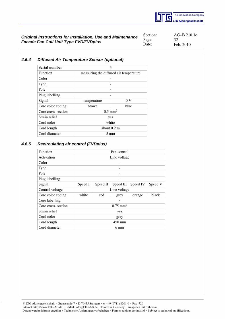
4.6.4 Diffused Air Temperature Sensor (optional)
Serial number 4
Function measuring the diffused air temperature
Color --
Type --
Pole --
Plug labelling --
Signal temperature 0 V
Core color coding brown blue
Core cross--section 0.5 mm2
Strain relief yes
Cord color white
Cord length about 0.2 m
Cord diameter 5 mm
4.6.5 Recirculating air control (FVDplus)
Function Fan control
Activation Line voltage
Color --
Type --
Pole --
Plug labelling --
Signal Speed I Speed II Speed III Speed IV Speed V
Control voltage Line voltage
Core color coding white red grey orange black
Core labelling --
Core cross--section 0.75 mm2
Strain relief yes
Cord color grey
Cord length 450 mm
Cord diameter 6 mm
Original Instructions for Installation, Use and MaintenanceFacade Fan Coil Unit Type FVD/FVDplus
Section:Page:Date:
AG--B 210.1e33Feb. 2010
The Innovation Company
LTG Aktiengesellschaft
E LTG Aktiengesellschaft ⋅ Grenzstraße 7 ⋅ D-70435 Stuttgart ⋅ +49 (0711) 8201-0 ⋅ Fax -720Internet: http://www.LTG-AG.de ⋅ E-Mail: [email protected] ⋅ Printed in Germany ⋅ Ausgaben mit früheremDatum werden hiermit ungültig ⋅ Technische Änderungen vorbehalten ⋅ Former editions are invalid ⋅ Subject to technical modifications.
4.7 Check after Installation
Verify for the unit’s proper connection to a residual current device (RCD).
Mechanical CheckHaving completed the installation the unit is to be checked for any mechanical damages. Remainders of thepackaging material and dust in or on the unit must be removed.
Check the following:
- leakproofness of the water connections (including heat exchanger connections),
- the insulation of all cold water carrying components to the heat exchanger for damage,
- the fixing screws for proper fit,
- the unit for not contacting the facade and the raw floor except via the seals provided and the supporting feet(floor units),
- the fine filter for proper installation (direction of air flow),
- the line voltage and frequency to match the data given on the type plate,
- the electrical connections for proper execution and conformity to pertinent regulations,
- proper functioning of the control (optional),
- proper functioning of the motors (actuators) without friction noises,
- the unit’s fixation,
- the diffusion area/diffusion grille of the unit to be free of any obstructions,
- proper horizontal alignment, accurate to dimension,
- sufficient water hose lengths and strainless laying,
- if required, for tightness of the unit’s connection to the outside air suction duct,
- protective board (chipboard) removed.
Check for Media Supply- Check for proper availability of primary air, cold water, warm water, and electrical power.
- Check whether voltage and line frequency comply with the data given on the type plate of the terminal box.Never operate control devices with inappropriate voltage or frequency since this might result in destructionof the units and put people at risk.
Control Technical EquipmentSupply of control devices by LTG Aktiengesellschaft is optional, however it is the rule for actuators for unitswith dampers. Control valves are often factory--mounted.
Starting Standard OperationThen set the temperature controller to the desired temperature. After a certain time the indoor air temperatureshould meet the setpoint.
Original Instructions for Installation, Use and MaintenanceFacade Fan Coil Unit Type FVD/FVDplus
Section:Page:Date:
AG--B 210.1e34Feb. 2010
The Innovation Company
LTG Aktiengesellschaft
E LTG Aktiengesellschaft ⋅ Grenzstraße 7 ⋅ D-70435 Stuttgart ⋅ +49 (0711) 8201-0 ⋅ Fax -720Internet: http://www.LTG-AG.de ⋅ E-Mail: [email protected] ⋅ Printed in Germany ⋅ Ausgaben mit früheremDatum werden hiermit ungültig ⋅ Technische Änderungen vorbehalten ⋅ Former editions are invalid ⋅ Subject to technical modifications.
5. First UsePrior to first use any installation work and all checks must have been completed.
Check for proper water and power supply.
Prior to putting into operation the protective board (chipboard) is to be re-moved. Otherwise overheating may result in damage to the motor unit.
Having started the unit an air flow should be perceivable from the floor grille. Only very minor air diffusionandmotor sounds should be audible. Other sounds such as friction or impact might indicate damages resultingfrom transport or installation.
5.1 Selecting the Outside Air Flow RateAfter proper installation by an expert the facade fan coil unit may be turned ”off” at the operating panel (onsite) (e.g. via a presence switch or the fan speed level ”0”) or may be operated at speed ”I”, ”II”, or ”III”.
The outside air flow rate related to each speed level is usually preset according to customer’s and project re-quirements. If no--load switching is a requirement with the unit ”off”, this should be realized with an about180--second time delay after switching to speed ”0” since the damper might otherwise be shut by the springreturn causing more noise.
If operating properly the fan will start moving, having switched on the unit, and the outside air damper willopen. Outside air will be sucked through the filter, heated or cooled by the heat exchanger, and diffused intothe room.
It is recommended to select the outside air flow rate in compliance with your needs, e.g. depending on thenumber of personsgathered. Please refer to the minimum air volume regulations of DIN 1946 Part 2. On theother hand, the outside air flow rate should be kept as low as possible to save energy.
Here a few ideas how to use the unit efficiently:
- Switch the unit off or set it to a lower level if the room is not being used.
- If opening the windows is permitted, switch the unit off while windows are open or in between seasons.
- Switch the unit to a lower level during winter and when the outside air temperature is very low if you thinkthat sufficient fresh air is entering the room and that the indoor air is quite dry.
The unit’s primary function is to provide fresh air to the room. In case of extremely high or low outside airtemperatures or in case of high thermal loads the unit’s capacity might be insufficient to maintain the desiredroom temperature. Therefore, it is usually combined with other indoor air conditioning systems such as con-crete core temperature control.
5.2 Emergency Closing FunctionIn case of an emergency such as fire or ”gas alarm” it is desirable to keep outside air from entering and to sealthe facade.
Therefore, the facade fan coil unit’s outside air damper is provided with a spring return motor. In case of apower failure or when switched off (contrary to the switched fan level ”0”) the outside air damper will beclosing automaticallywithin a few seconds. Closing by spring, however, produces a little bitmore noisewhichis why for the standard closing procedure switching to level ”0” is to be preferred (unit is supplied with230 V AC, however with no connection of the control line to any of the three fan speed lines).
Original Instructions for Installation, Use and MaintenanceFacade Fan Coil Unit Type FVD/FVDplus
Section:Page:Date:
AG--B 210.1e35Feb. 2010
The Innovation Company
LTG Aktiengesellschaft
E LTG Aktiengesellschaft ⋅ Grenzstraße 7 ⋅ D-70435 Stuttgart ⋅ +49 (0711) 8201-0 ⋅ Fax -720Internet: http://www.LTG-AG.de ⋅ E-Mail: [email protected] ⋅ Printed in Germany ⋅ Ausgaben mit früheremDatum werden hiermit ungültig ⋅ Technische Änderungen vorbehalten ⋅ Former editions are invalid ⋅ Subject to technical modifications.
5.3 Constant Flow Rate Controller / Wind Pressure ControllerMaintenance of the desired outside air flow rate, depending onwind pressures applied to the suction opening,is ensured by a controller integrated in the fan performance electronic.
With an existing underpressure at the suction opening, the fan will have to work harder to provide the desiredoutside air flow rate to the room, thus producing more sound -- a normal operating condition. If the pressureloss results in the fan reaching its performance limit it will be shut off by the fan’s internal control with anabout 3--minute delay. This is a regular reaction, not a failure. It compares to closing awindowona verywindyday. After about 10 minutes the unit will automatically restart and try to resume standard operation.
However, this ”constant flow rate control” will continue to balance larger pressure losses within the unit. Forexample, if the filter is polluted or the outlet grille misaligned the internal control will do its best to provideadequate balancing. But again, this might increase the fan’s noise level. An considerable noise level increasemight be the result of clogged air paths.
5.4 AntifreezeSince the heat exchanger of decentralized air conditioning units is, at least partly, provided with outside airthe heat exchanger is subject to a potential freezing risk in case the warm water supply fails (e.g. resultingfrom fan drive failure).
This failure may be detected by monitoring the diffused air temperature, i.e. before resulting in a damage tothe heat exchanger. An optional digital antifreeze sensor monitoring the diffused air temperature will shut offthe fan if the temperature drops below a limit of 10_Cand will close the outside air damper.
In case of proper unit and control functions, this condition should not occur neither in the cooling nor in theheating mode.
If you witness such shut--off operation (which may otherwise only occur if the unit’s fan reaches its perfor-mance limit) please have your technicians check the unit. If the sensor temperature is rising to 15_C or higher,the unit will automatically restart and try to resume its standard operation.
Original Instructions for Installation, Use and MaintenanceFacade Fan Coil Unit Type FVD/FVDplus
Section:Page:Date:
AG--B 210.1e36Feb. 2010
The Innovation Company
LTG Aktiengesellschaft
E LTG Aktiengesellschaft ⋅ Grenzstraße 7 ⋅ D-70435 Stuttgart ⋅ +49 (0711) 8201-0 ⋅ Fax -720Internet: http://www.LTG-AG.de ⋅ E-Mail: [email protected] ⋅ Printed in Germany ⋅ Ausgaben mit früheremDatum werden hiermit ungültig ⋅ Technische Änderungen vorbehalten ⋅ Former editions are invalid ⋅ Subject to technical modifications.
6. Operation, Maintenance and RepairAll units are virtually maintenance free, however certain things should be observed.
Any maintenance and repair work must be performed by skilled and trainedstaff only.
Before starting any maintenance or repair work the unit is to be completelydisconnected from the main power supply!
6.1 RepairIf the damage is not obviously a mere ”damage to the bodywork”, e.g. on the condensate tray or outlet, unitsshould be completely replaced and checked by the factory (in case of defects to the fan it might be sufficientto replace the fan unit without need to disconnect the system entirely from the water supply system).
First, the unit is to be completely disconnected from the power supply by an expert.
Replacement of the control unit should be performed by skilled staff onlyor by the factory.
Replacement of individual components, e.g. a fan bearing, is not recommen-ded since the greater number of settings can only be performed in the fac-tory using special equipment.
Warranty applies to complete fans only.
Original Instructions for Installation, Use and MaintenanceFacade Fan Coil Unit Type FVD/FVDplus
Section:Page:Date:
AG--B 210.1e37Feb. 2010
The Innovation Company
LTG Aktiengesellschaft
E LTG Aktiengesellschaft ⋅ Grenzstraße 7 ⋅ D-70435 Stuttgart ⋅ +49 (0711) 8201-0 ⋅ Fax -720Internet: http://www.LTG-AG.de ⋅ E-Mail: [email protected] ⋅ Printed in Germany ⋅ Ausgaben mit früheremDatum werden hiermit ungültig ⋅ Technische Änderungen vorbehalten ⋅ Former editions are invalid ⋅ Subject to technical modifications.
6.1.1 Facade Module
Remove the traffic resistant grille to get access to the maintenance cover and heat exchanger to perform anymaintenance and repair work on the facade module.
openTo open the maintenance cover: Push it slightly indirection to the heat exchanger until the locking isreleased (compare pictures).
This will grant access to the filter, the actuator, andthe outside air damper.
To close themaintenance cover: Push it again slightlyaway from the heat exchanger until it snaps in.
Original Instructions for Installation, Use and MaintenanceFacade Fan Coil Unit Type FVD/FVDplus
Section:Page:Date:
AG--B 210.1e38Feb. 2010
The Innovation Company
LTG Aktiengesellschaft
E LTG Aktiengesellschaft ⋅ Grenzstraße 7 ⋅ D-70435 Stuttgart ⋅ +49 (0711) 8201-0 ⋅ Fax -720Internet: http://www.LTG-AG.de ⋅ E-Mail: [email protected] ⋅ Printed in Germany ⋅ Ausgaben mit früheremDatum werden hiermit ungültig ⋅ Technische Änderungen vorbehalten ⋅ Former editions are invalid ⋅ Subject to technical modifications.
6.1.1.1 Filter ChangeIt is recommended to replace the filter as needed, however, at least once a year.
Remove the filter cover: Slightly press the centerof the filter cover and, at the same time, unlock thecover onone front side. Thenunlock the cover on theopposite side and remove.
This will grant access to the filter.
Filter change: Carefully pull out the filter with anupward movement.
Spare filters may be ordered fromLTG Aktiengesellschaft in Stuttgart.
Please indicate the filter type stated on the productlabel when ordering.
Carefully insert the filter vertically from above intothe frame. Check for proper seating in a centered po-sition and for the right direction (arrow indicatingthe air direction).
Reinsert the filter cover on one front side andsnap in.
Slightly press the center of the filter cover and, at thesame time, snap in on the opposite front side.
Close maintenance cover and snap in.
Reinsert foot traffic resistant grille.
Original Instructions for Installation, Use and MaintenanceFacade Fan Coil Unit Type FVD/FVDplus
Section:Page:Date:
AG--B 210.1e39Feb. 2010
The Innovation Company
LTG Aktiengesellschaft
E LTG Aktiengesellschaft ⋅ Grenzstraße 7 ⋅ D-70435 Stuttgart ⋅ +49 (0711) 8201-0 ⋅ Fax -720Internet: http://www.LTG-AG.de ⋅ E-Mail: [email protected] ⋅ Printed in Germany ⋅ Ausgaben mit früheremDatum werden hiermit ungültig ⋅ Technische Änderungen vorbehalten ⋅ Former editions are invalid ⋅ Subject to technical modifications.
6.1.1.2 Replacing the Actuator
Type FVD- Remove filter as described in chapter 6.1.1.1
- Remove the actuator terminals starting with the red core, then the white one labelled ”3”, then the blackone, and finally the white core labelled ”5”.
- Remove the aluminum sticker on the filter frame’s lateral side.
- Remove M6 screws and nuts.
- Pull actuator from the damper shaft.
- Remove the actuator.
- Remove the control cam and the safety ring from the actuator. Mark the direction of rotation and theposition.
Make sure to reinstall the control cam, locking ring,and end stop in their proper positions (illustrated forFVD--A--1245--200--L).
- Mount control cam and locking ring to the new actuator. Ensure proper position and direction of rotation.
- Install the new actuator on the damper shaft and ensure proper positioning.
- Tighten actuator with M6 screws and nuts.
- Connect actuator according to wiring diagram. Start with the white core labelled ”5”, followed by the blackcore and the white core labelled ”3”, and finally the red core.
black (1)
white 4
white 5
red 2
Transfo230 V / 24 V
n.c.
y
24 V
GND
Belimoactuator
- Properly position the actuator’s connecting cord.
- Check the actuator for proper functioning.
- Seal the opening in the filter frame’s lateral panel with a new aluminum sticker!
- Reinstall filter as described in chapter 6.1.1.1.
Original Instructions for Installation, Use and MaintenanceFacade Fan Coil Unit Type FVD/FVDplus
Section:Page:Date:
AG--B 210.1e40Feb. 2010
The Innovation Company
LTG Aktiengesellschaft
E LTG Aktiengesellschaft ⋅ Grenzstraße 7 ⋅ D-70435 Stuttgart ⋅ +49 (0711) 8201-0 ⋅ Fax -720Internet: http://www.LTG-AG.de ⋅ E-Mail: [email protected] ⋅ Printed in Germany ⋅ Ausgaben mit früheremDatum werden hiermit ungültig ⋅ Technische Änderungen vorbehalten ⋅ Former editions are invalid ⋅ Subject to technical modifications.
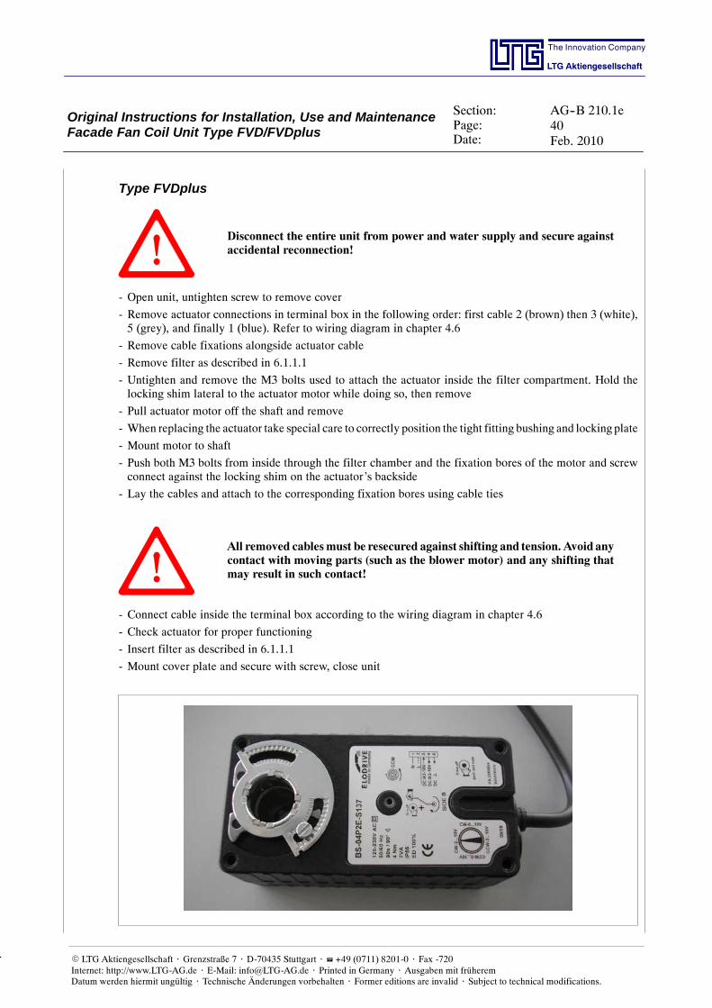
Type FVDplus
Disconnect the entire unit from power and water supply and secure againstaccidental reconnection!
- Open unit, untighten screw to remove cover
- Remove actuator connections in terminal box in the following order: first cable 2 (brown) then 3 (white),5 (grey), and finally 1 (blue). Refer to wiring diagram in chapter 4.6
- Remove cable fixations alongside actuator cable
- Remove filter as described in 6.1.1.1
- Untighten and remove the M3 bolts used to attach the actuator inside the filter compartment. Hold thelocking shim lateral to the actuator motor while doing so, then remove
- Pull actuator motor off the shaft and remove
- When replacing the actuator take special care to correctly position the tight fitting bushing and lockingplate
- Mount motor to shaft
- Push both M3 bolts from inside through the filter chamber and the fixation bores of the motor and screwconnect against the locking shim on the actuator’s backside
- Lay the cables and attach to the corresponding fixation bores using cable ties
All removed cablesmust be resecured against shifting and tension. Avoid anycontact with moving parts (such as the blower motor) and any shifting thatmay result in such contact!
- Connect cable inside the terminal box according to the wiring diagram in chapter 4.6
- Check actuator for proper functioning
- Insert filter as described in 6.1.1.1
- Mount cover plate and secure with screw, close unit
Original Instructions for Installation, Use and MaintenanceFacade Fan Coil Unit Type FVD/FVDplus
Section:Page:Date:
AG--B 210.1e41Feb. 2010
The Innovation Company
LTG Aktiengesellschaft
E LTG Aktiengesellschaft ⋅ Grenzstraße 7 ⋅ D-70435 Stuttgart ⋅ +49 (0711) 8201-0 ⋅ Fax -720Internet: http://www.LTG-AG.de ⋅ E-Mail: [email protected] ⋅ Printed in Germany ⋅ Ausgaben mit früheremDatum werden hiermit ungültig ⋅ Technische Änderungen vorbehalten ⋅ Former editions are invalid ⋅ Subject to technical modifications.
6.1.1.3 Replacing the Outside Air Damper- Remove the filter as described in chapter 6.1.1.1.
- Remove the actuator as described in chapter 6.1.1.2. Cords will not necessarily have to be removed.
- Untighten the M5 screws on the filter frame.
- If necessary, remove pressure hoses for filter monitoring.
- Remove filter frame by pulling it straight up.
- Carefully pull out the outside air damper housing and remove by pulling it straight up.
- If necessary, carefully remove the damper insulation.
- If necessary, fix insulation to new damper housing.
- Install the new damper housing with the adhesive seal (self--swelling, hydrophobic)the same way and push in direction to the facade into the outside air suction duct untilthe filter frame can be remounted.
- Reinstall filter frame. If necessary, replace seals.
- Reinstall M5 screws into the filter frame.
- Remount the actuator as described in chapter 6.1.1.2.
- Reinstall filter as described in chapter 6.1.1.1.
- If necessary, reinstall pressure hoses for filter monitoring.
Original Instructions for Installation, Use and MaintenanceFacade Fan Coil Unit Type FVD/FVDplus
Section:Page:Date:
AG--B 210.1e42Feb. 2010
The Innovation Company
LTG Aktiengesellschaft
E LTG Aktiengesellschaft ⋅ Grenzstraße 7 ⋅ D-70435 Stuttgart ⋅ +49 (0711) 8201-0 ⋅ Fax -720Internet: http://www.LTG-AG.de ⋅ E-Mail: [email protected] ⋅ Printed in Germany ⋅ Ausgaben mit früheremDatum werden hiermit ungültig ⋅ Technische Änderungen vorbehalten ⋅ Former editions are invalid ⋅ Subject to technical modifications.
6.1.2 Ventilation Module
Disconnect the unit from the main power supply in all poles before opening theventilation module.
Depending on the unit version the 3--pole repair connector shownbelowmaybe used for disconnection. Shapeand brand of repair connectors may vary depending on the unit version or completely different disconnectorsmay be used by the customer.
Please always observe the wiring diagrams of electrotechnical installations!
Open the ventilation module using a siphon. There is no need to untighten any screws.
This provides access to both the fan and the sound absorber.
Original Instructions for Installation, Use and MaintenanceFacade Fan Coil Unit Type FVD/FVDplus
Section:Page:Date:
AG--B 210.1e43Feb. 2010
The Innovation Company
LTG Aktiengesellschaft
E LTG Aktiengesellschaft ⋅ Grenzstraße 7 ⋅ D-70435 Stuttgart ⋅ +49 (0711) 8201-0 ⋅ Fax -720Internet: http://www.LTG-AG.de ⋅ E-Mail: [email protected] ⋅ Printed in Germany ⋅ Ausgaben mit früheremDatum werden hiermit ungültig ⋅ Technische Änderungen vorbehalten ⋅ Former editions are invalid ⋅ Subject to technical modifications.
6.2 Maintenance Intervals of the Individual ComponentsThe stated activities should be performed about every 6 to 12 months, depending on the environmental condi-tions.
We recommend to change the filter late in autumn in order not to leave pollen and other particles in the filterduring the winter.
In case of a change every 6 months, we recommend to perform an additional change in spring at the end ofthe heating period.
Indoor air control (optional)
Component ActivityTo be performed
months as needed
Operating unit Check for pollution, damages, corrosion, and properfunctioning 12
Controller Check for proper functioning of the supply air ther-mal cut--out 12
Unit in general
Component ActivityTo be performed
months as needed
Unit in general
Check for pollution, damages, corrosion, correct fitand fixation 12
Check suction socket for proper and tight fit to out-side air suction duct 12
Check unit for proper fit to facade and false floor 12
Ventilation module
Component ActivityTo be performed
months as needed
Fan
Check for pollution, damages, corrosion, and properfixation 12
Clean to maintain function xCheck bearing for imbalance 12Check bearing for noises 12Check vibration damper for proper function 12Check safety devices for proper function 12Check for sanitation 6
Fan and sound ab-sorber chamber
Check for pollution, damages, and corrosion 12Clean to maintain function xCheck heat insulation for damages(visual inspection) x
Clean chamber from the inside xCheck for sanitation x x
Valves and valveactuators
Check for pollution, damages, corrosion, and properfunction 12
Original Instructions for Installation, Use and MaintenanceFacade Fan Coil Unit Type FVD/FVDplus
Section:Page:Date:
AG--B 210.1e44Feb. 2010
The Innovation Company
LTG Aktiengesellschaft
E LTG Aktiengesellschaft ⋅ Grenzstraße 7 ⋅ D-70435 Stuttgart ⋅ +49 (0711) 8201-0 ⋅ Fax -720Internet: http://www.LTG-AG.de ⋅ E-Mail: [email protected] ⋅ Printed in Germany ⋅ Ausgaben mit früheremDatum werden hiermit ungültig ⋅ Technische Änderungen vorbehalten ⋅ Former editions are invalid ⋅ Subject to technical modifications.
Facade Module
Component ActivityTo be performed
months as needed
Fine filter
Check for pollution, damages, and corrosion xCheck filter covering for tightness xReplace filter medium and document 12Check for sanitation 6
Damper motor
Check the exterior for pollution, fixation, dama-ges, and corrosion 12
Clean to maintain function xCheck terminals for proper fit xCheck for smooth running and possible heating up xCheck safety devices for proper function(spring return) 12
Outside air damperwith seal
Check for pollution, damages, corrosion, and pro-per mechanical function 12
Filter--to--fan duct
Check duct section including existing heat insula-tion and fixation for exterior damages and corro-sion
x
Random check the duct section interior for pollu-tion (visual inspection), check for sanitation x
Heat exchanger
Check for pollution, damages, and corrosion 6Clean to maintain function (air side) xCheck water connections 12Ventilate xCheck for sanitation 6
Antifreeze sensorCheck for pollution, damages, and corrosion 12Check safety devices for proper function (frostprotection) 12
Original Instructions for Installation, Use and MaintenanceFacade Fan Coil Unit Type FVD/FVDplus
Section:Page:Date:
AG--B 210.1e45Feb. 2010
The Innovation Company
LTG Aktiengesellschaft
E LTG Aktiengesellschaft ⋅ Grenzstraße 7 ⋅ D-70435 Stuttgart ⋅ +49 (0711) 8201-0 ⋅ Fax -720Internet: http://www.LTG-AG.de ⋅ E-Mail: [email protected] ⋅ Printed in Germany ⋅ Ausgaben mit früheremDatum werden hiermit ungültig ⋅ Technische Änderungen vorbehalten ⋅ Former editions are invalid ⋅ Subject to technical modifications.
7. ControlConsider the following special features when including a facade fan coil unit type FVD/FVDplus into a con-trol circuit:
The heat exchanger of the decentralized facade fan coil unit type FVD/FVDplus is providedwith both outsideand indoor air. Since the outside air temperature is subject to major fluctuations compared to the suction tem-perature of regular recirculating air units, off--the--shelf control strategies for fan coil units cannot be appliedwithout realizing certain modifications.
7.1 Room Temperature ControllerThe room temperature must be cascade controlled in a way to ensure that the desired room temperature isachieved in the occupied zone.This requires continuous valve actuators.
In order to ensure a continuous control of valves, the unit, and the control system, i.e. to provide a steady sup-ply air temperature, the hot water supply temperaturemust be controlled according to the outside air tempera-ture.
7.2 Wind Pressure Control / Supply Air Flow RateMaintenance of the required outside air flow rate, depending on appliedwindpressures at the suctionopening,is ensured by a controller integrated in the fan’s performance electronic. There is no outside access to thiscontroller.
Three speed levels to be connected complywith the nominal flow rates specified by the customer (e.g. 90m3/h-- 120 m3/h -- 150 m3/h). If no flow rate is activated the unit will close the outside air damper and put the fanto a stop. The desired outside air volume may be selected, i.e. switched, by an external control from threegiven flow rates.
If the unit is not voltage supplied the outside air damper will close in the spring return mode.
7.3 AntifreezeSince the heat exchanger of decentralized air conditioning units is, at least partly, supplied by outside air thereis a freezing risk to the heat exchanger in case of a warm water supply failure (e.g. when the fan drive fails).
Such failure may be detected in time, before causing any damage to the heat exchanger, by monitoring thediffused air temperature.An optional digital antifreeze sensormonitoring the diffused air temperature shuts off the fanwhen the tempe-rature falls below a set limit of 10 _C and closes the outside air damper. If the unit is operating properly thisworking point will not be achieved neither in the heating nor in the cooling mode.
The digital antifreeze sensor does not protect from a simultaneous failure of the control. Maximum safety isachieved when using an additional antifreeze controller with capillary tube sensor as redundant system.
When exceeding the sensor temperature of 15 _C the unit resumes its operation.
An external control may additionally capture the diffused air temperature (supplemental diffused air tempera-ture sensor). There, further error messages may be transmitted and the outside air damper may be closed(fan -- nominal flow rate 0).
7.4 Diffused Air Temperature LimitingOptimizing the thermal comfort for people in the occupied zone requires diffused air temperaturemonitoringand lower valve setting limiting.
It should not drop more than 8 Kelvin below room temperature.
However, this will also limit an available cooling capacity.
Original Instructions for Installation, Use and MaintenanceFacade Fan Coil Unit Type FVD/FVDplus
Section:Page:Date:
AG--B 210.1e46Feb. 2010
The Innovation Company
LTG Aktiengesellschaft
E LTG Aktiengesellschaft ⋅ Grenzstraße 7 ⋅ D-70435 Stuttgart ⋅ +49 (0711) 8201-0 ⋅ Fax -720Internet: http://www.LTG-AG.de ⋅ E-Mail: [email protected] ⋅ Printed in Germany ⋅ Ausgaben mit früheremDatum werden hiermit ungültig ⋅ Technische Änderungen vorbehalten ⋅ Former editions are invalid ⋅ Subject to technical modifications.
7.5 Starting CircuitIn order to avoid that low outside air temperatures will result in the heat exchanger temperature dropping be-low 10 _C (mixed temperature of outside air and recirculated air), the heat exchanger must be supplied withhot water before starting the unit.
7.6 Night Cooling
Using a suitable control strategy the facade fan coil unit may equally be used to cool the building structurewhen night temperatures are low (as long as they don’t drop below 10 _C)
7.7 Minimum Air VolumeTominimize energy expenses the outside air volume should be adapted to the need of the persons in the corres-ponding office units.
7.8 Recirculating Air ModeMake sure by means of control strategy that the recirculating air fan is running whenever the unit is operatingin the outside airmode. Otherwise proper functioningof the unit will be compromisedpossibly affecting com-fort in the occupied zone.
Original Instructions for Installation, Use and MaintenanceFacade Fan Coil Unit Type FVD/FVDplus
Section:Page:Date:
AG--B 210.1e47Feb. 2010
The Innovation Company
LTG Aktiengesellschaft
E LTG Aktiengesellschaft ⋅ Grenzstraße 7 ⋅ D-70435 Stuttgart ⋅ +49 (0711) 8201-0 ⋅ Fax -720Internet: http://www.LTG-AG.de ⋅ E-Mail: [email protected] ⋅ Printed in Germany ⋅ Ausgaben mit früheremDatum werden hiermit ungültig ⋅ Technische Änderungen vorbehalten ⋅ Former editions are invalid ⋅ Subject to technical modifications.
8. Spare PartsThe following spare parts are available andmay be ordered fromLTG Aktiengesellschaft stating unit typeand description.
Quan-tity Ident No. Description Minimum
order quantity
1 1019431 Fan FVD, G1G 146 1
1 1019562 Electric motor damper LF 24--SR 1
1 1019621 Filter FVD F5 230 x 110 x 70 10
1 1024753 Terminal box FVD--A 1
1 Heat exchanger (depending on project) 1
1 1019607 Line sensor PT 1000 with 7 m cord 5
1 1019622 Digital sensor for FVD with 2 m cord 1
1 1024858 Fan FVDplus G1G 146 1
1 1020194 Motor 5--speed 1
1 1029670 Filter F7 10
1 1040318 Terminal box box FVDplus 1
1 1040320 Diffused air temperature sensor PT 1000 1
1 1004190 Capacitor 1 F 1
Please state connection for heat exchangers (1/2”, smooth copper pipe).
9. Decommissioning, disposalWhen the fan is taken out of service, is no longer used and is disposed of as waste, the followingmust be com-plied with:
- all steel parts are waste for recycling
- all plastic parts are waste for recycling
- all secondary substances and lubricants must be disposed of in accordance with the provisions of the EWC(European Waste Catalogue) classification.