26
ANDI-SERVO Dual Servo Motor Controller PC/104 Card Technical Reference Manual Rev 2.0 Jan 19, 1999
ANDI-SERVO
Dual Servo Motor Controller PC/104 Card
Technical Reference Manual
Rev 2.0 Jan 19, 1999

ANDI-SERVO TECHNICAL REFERENCE MANUAL
1
NOTICE
A. DISCLAIMER
The contents of this manual has been carefully checked and is believed to beentirely reliable. However, no responsibility is assumed for inaccuracies. Ajecoreserves the right to make changes to any products described herein to improvereliability, function or design. Ajeco shall under no circumstances be liable forincidental or consequential damages or related expenses resulting from use ofproducts or circuits mentioned herein, even if it has been notified of the possibility ofsuch damages. Ajeco reserves the right to revise this manual without obligation tonotify any person of such a revision. When this document contains information on anew product, specifications herein are subject to change without notice.
COPYRIGHT© AJECO OY(INC)TAKKATIE 7 A, FIN-00370 HELSINKI, FINLANDTelephone: +358-9-7003-9200, Telefax: [email protected] www.ajeco.com
B. CAUTION!
C. TRADEMARKS
All trademarks are the property of their respective owners.
1. ALWAYS CHECK voltage levels before connecting any ANDI-SERVO interfacepin to any device or voltage source. DO NOT INTERCONNECT any ANDI-SERVO interface pins before checking voltage levels and pinouts on connectors.
2. DO NOT SHORT or ground any output.
3. AVOID STATIC ELECTRICITY. The products herein contains devices that mightbe damaged by static electricity.
SERIOUS DAMAGE may result to ANDI-SERVO and/or the computer andWARRANTY will be VOID if these rules are not followed.

ANDI-SERVO TECHNICAL REFERENCE MANUAL
2
Dear Customer,
Thank you for purchasing the ANDI-SERVO Dual Servo Motor Controller board. Webelieve the quality, reliability and overall performance of this product will help youachieve a completely satisfactory dual servo motor controlling system.
Please, fill in, and return the customer support and warranty form. In doing so, wewill be more able to help you in situations requiring technical assistance. Your nameand address will not be used in any other context except for our internal use, i.e.customer support.
In case you would need technical assistance, although we do not anticipate you willencounter any problems using the ANDI products, please document the situationthoroughly and contact Ajeco by telefax or letter. We also greatly appreciate if youhave specific ideas, that might help us improve our products. Please send us yourideas in writing.
Finally, We wish to thank you once again for your excellent choice of ANDI products.
Sincerely Yours,
AJECO INC (OY)

ANDI-SERVO TECHNICAL REFERENCE MANUAL
3
CUSTOMER SUPPORT AND WARRANTY FORM:
Please fill this form and return it to Ajeco. This information is essential for supportingyou in the future. Use capital block letters.
Name:____________________________________________________________
Company:_________________________________________________________
Address: _________________________________________________________
City/State/Zip: _____________________________________________________
Phone: ___________________________________________________________
Telefax: __________________________________________________________
Date of purchase:___________________________________________________
Place of purchase:__________________________________________________
ANDI-SERVO card number:___________________________________________
Notes:____________________________________________________________
_________________________________________________________________
_________________________________________________________________
_________________________________________________________________
_________________________________________________________________
_________________________________________________________________
_________________________________________________________________
Send this form by email or use telefax.
AJECO OY, TAKKATIE 7A, FIN-00370 HELSINKI, FINLAND.Telefax: +358-9-7003-9209 [email protected]

ANDI-SERVO TECHNICAL REFERENCE MANUAL
4
TABLE OF CONTENTS
1 General ............................................................................................................ 5
1.1 Building a System....................................................................................... 6
2 HARDWARE..................................................................................................... 7
2.1 Base Address Selection.............................................................................. 7
2.2 Interrupt Line Selection............................................................................... 8
2.3 Motor Connector P3.................................................................................... 9
2.4 Encoder connector P1 .............................................................................. 11
2.5 Auxiliary PWM-output connector P2......................................................... 12
2.6 Fault LED.................................................................................................. 13
2.7 Technical specifications ........................................................................... 13
2.8 Board Layout ............................................................................................ 14
2.9 Connector Locations................................................................................. 15
2.10 Block Diagram .......................................................................................... 16
3 FUNCTIONAL DESCRIPTION ....................................................................... 17
3.1 General Description.................................................................................. 17
3.2 Features ................................................................................................... 17
3.3 Theory of Operation.................................................................................. 18
3.3.1 Introduction......................................................................................... 18
3.3.2 Position feedback interface ................................................................ 18
3.3.3 Velocity profile (trajectory) generation ................................................ 19
3.3.4 PID compensation filter....................................................................... 21
3.4 Typical Applications.................................................................................. 23
3.4.1 Programming LM629 Host Handshaking (Interrupts) ......................... 23
3.4.2 Incremental Encoder Interface............................................................ 23
3.4.3 I/O port usage (I/O map)..................................................................... 24
4 SOFTWARE FUNCTIONS ............................................................................. 25
ANDI-SERVO TECHNICAL REFERENCE MANUAL
5
CHAPTER 1
INTRODUCTION
1 General
ANDI-SERVO is a two axis DC-servo motor-controller board for closed looppositioning applications. The board features a motor-controller processor anda H-bridge power output stage for each axis.
Controlling and driving a DC-servomechanism is a difficult task. The motor-controller is required to perform its computing in real-time and the mechanicalsystem often involves torques and forces of a resonant nature. Mechanicalsystems have characteristics familiar to electronics; step response times,latency, resonance, damping etc. It is the duty of a motor-controller processorto ensure that the desired motion is performed with optimum result, evenunder non-ideal conditions.
The motor-controller processors on ANDI-SERVO can be parametrized foroptimum performance. 32-bit position, velocity and acceleration registers, aprogrammable PID-filter with 16-bit coefficients and a programmablederivative sampling interval are keys to a successful implementation.
ANDI-SERVO can be used in both position- and velocity-mode systems. Inthe first mode, The board accelerates the motor to the desired velocity, whileit is constantly monitoring the feedback to see if a desired position is reached.The board stops the motor movement, smoothly or abruptly, precisely at thedesired position. In the velocity mode, the board maintains a constant velocityat a motor until the board is instructed to stop.
The ANDI-SERVO is shipped with a comprehensive software library in 'C' withover 40 functions serving as an interface to the motor-controller processor.
We recommend downloading the National Semiconductor’s application notesand specifications sheets as they contain valuable information forprogrammers and systems integrators. The AN-693 Programming Guide andAN-706 User Guide can be downloaded from Ajeco’s web site atwww.ajeco.com
ANDI-SERVO TECHNICAL REFERENCE MANUAL
6
1.1 Building a System
The ANDI-SERVO base address must be set before it can be accessed from thehost computer. The board needs 8 continuous I/O addresses, and the demo/testprograms assume that base 300h can be used. Close the base jumpers 0through 3, leave 4 open to configure the board for base 300h. The interrupt line isnot needed at this stage.
The possibly easiest way to start developing a servo system, is to connect a shaftencoder and a (small energy) DC-motor to channel 1 of the board. The shaftencoder can for example be a Bourns ENS1J-B28-L00256, or Hewlett-PackardHEDS-5700 series. Any "standard" industrial incremental shaft encoders can beused. Encoders that are equipped with a separate index signal can also be used.(See sections: Motor Connector P3, Encoder Connector P1).
Apply a Vmotor voltage to the Motor Connector P3. Observe that the PWM-outputH-bridge features an undervoltage lockout (9Vmin...11Vmax) at which the outputsturn OFF. Select a DC-motor that runs OK with 12...24 Vdc. Providecorrespondingly a sufficient motor voltage (Vmotor) of +12..+24 Vdc.
Run the demo program supplied on the board’s software diskette. The demoprogram reads the shaft encoder and writes the result on the computer screen.The shaft encoder values should change on the screen, when manually rotatingits axis. The DC-motor should also respond accordingly.
When the DC-motor and shaft encoder is properly connected to the board moreprecise and thorough software experimenting can begin.
Caution !
A typical pitfall, when building a closed loop positioning system, is that the twophase signals from the shaft encoder are interchanged. In this case, a "runoff"situation can occur. For example, the ANDI-SERVO board might drive the motorto one direction expecting that the encoder readout should decrease. If theencoders phase signals were interchanged, the encoder readout will increaseinstead of decrease, at which case the board will apply more force to the motor,driving it even further away from the desired position, rendering the motor withfull drive applied.

ANDI-SERVO TECHNICAL REFERENCE MANUAL
7
CHAPTER 2
2 HARDWARE
2.1 Base Address Selection
ANDI-SERVO has five jumpers for selecting the board’s base address. Thejumpers are located close to the PC/104 connector, labeled BASE 0 thoroughBASE 4. The boards base address must be set before it can be accessed fromthe host CPU. The board occupies 8 contiguous I/O addresses including theselected base address. (If base 300h is selected, addresses 300h through 307hwill be occupied by the board.)
The list describes how the jumper selections correspond with the selected baseaddress. When a jumper is closed (or mounted), it is referred to as a '0'. When ajumper is removed (dismounted), it is referred to as a '1'. The five jumpers enable32 different base addresses.
4 3 2 1 0Base Address
4 3 2 1 0Base Address
0 0 0 0 0 200h 1 0 0 0 0 300h0 0 0 0 1 210h 1 0 0 0 1 310h0 0 0 1 0 220h 1 0 0 1 0 320h0 0 0 1 1 230h 1 0 0 1 1 330h0 0 1 0 0 240h 1 0 1 0 0 340h0 0 1 0 1 250h 1 0 1 0 1 350h0 0 1 1 0 260h 1 0 1 1 0 360h0 0 1 1 1 270h 1 0 1 1 1 370h0 1 0 0 0 280h 1 1 0 0 0 380h0 1 0 0 1 290h 1 1 0 0 1 390h0 1 0 1 0 2A0h 1 1 0 1 0 3A0h0 1 0 1 1 2B0h 1 1 0 1 1 3B0h0 1 1 0 0 2C0h 1 1 1 0 0 3C0h0 1 1 0 1 2D0h 1 1 1 0 1 3D0h0 1 1 1 0 2E0h 1 1 1 1 0 3E0h0 1 1 1 1 2F0h 1 1 1 1 1 3F0h
Table A. Base Address of Jumpers 4 - 0
ANDI-SERVO TECHNICAL REFERENCE MANUAL
8
2.2 Interrupt Line Selection
ANDI-SERVO can be jumpered to use interrupt lines 2,3,4,5,6 or 7. The interruptline is selected by mounting a jumper block at the corresponding pins on theboard. The interrupt selection lines are labeled on the silk screen.
The board can generate interrupts from four sources: Both of the two H-bridgeoutput stages and both of the motor-controller processors can cause an interrupt.The interrupt lines are "OR"-ed on the board.
The interrupt source can be determined by reading the interrupt "cause" registerat BASE+6. The H-bridge output stage interrupts are purely diagnostic - theinterrupt is generated at an overheat condition. If the output stage is overheated(145 °C), it will cause an interrupt. The motor-controller processor is capable ofgenerating interrupts from a multitude of (programmable) sources.
When read, the BASE+6 register’s bits are decoded as follows:
Bit-0 If '1', Thermal flag interrupt from H-bridge output stage, channel-1Bit-1 If '1', Thermal flag interrupt from H-bridge output stage, channel-2Bit-2 If '1', Motor-controller processor at channel-1 interruptsBit-3 If '1', Motor-controller processor at channel-2 interrupts

ANDI-SERVO TECHNICAL REFERENCE MANUAL
9
2.3 Motor Connector P3
DC-, and brushless DC-motors can be connected to the ANDI-SERVO motorconnector, labeled with the text P3 on the board’s silk screen. The motor outputmethod is 8-bit sign/magnitude PWM.
The motor connector is an 8-pin field wiring connector with 5 mm pitch. The pinsare numbered from 1 through 8 having the following use:
Connector P3
Pin-1 Channel 2, PWM-drive output A
Pin-2 Channel 2, Vmotor, +12...50 Vdc input
Pin-3 Channel 2, GND (not isolated from computer, see Caution !)
Pin-4 Channel 2, PWM-drive output B
Pin-5 Channel 1, PWM-drive output A
Pin-6 Channel 1, Vmotor, +12...50 Vdc input
Pin-7 Channel 1, GND (not isolated from computer, see Caution !)
Pin-8 Channel 1, PWM-drive output B
Table 2. Connector P3
Caution !
Pay attention to potentially high motor voltages ! The absolute maximum voltagefor the PWM-stage is 55 Vdc. Exceeding this level can lead to damage to thecomputer system and the ANDI-SERVO card. Carefully check the pinout andvoltages before connecting to the board.
Pay attention that ANDI-SERVO is not isolated from the computer system. Theterminals marked with: GND, MUST be connected from the P3-connector to thesystem’s power supply ground, by own wires. This ensures that the motorground currents will be properly conducted to the system ground by NOT goingthrough the PC/104 stack !
The terminals marked with PWM-drive output A (and B) should be connected tothe DC-motor’s positive and negative terminals. Ensure that the DC-motorpower terminals are not connected to system ground. (Use a DC-motor whichhas a direction of rotation that can be reversed by changing the polarity at itsterminals).
ANDI-SERVO TECHNICAL REFERENCE MANUAL
10
Warning !
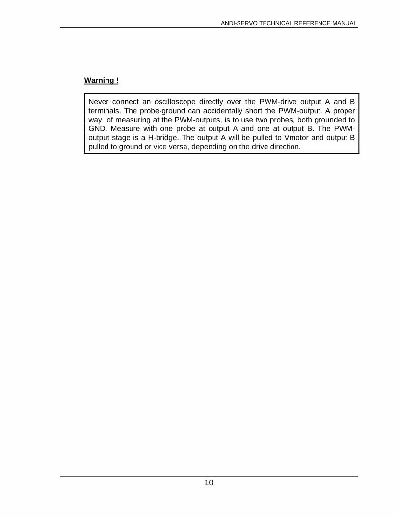
Never connect an oscilloscope directly over the PWM-drive output A and Bterminals. The probe-ground can accidentally short the PWM-output. A properway of measuring at the PWM-outputs, is to use two probes, both grounded toGND. Measure with one probe at output A and one at output B. The PWM-output stage is a H-bridge. The output A will be pulled to Vmotor and output Bpulled to ground or vice versa, depending on the drive direction.
ANDI-SERVO TECHNICAL REFERENCE MANUAL
11
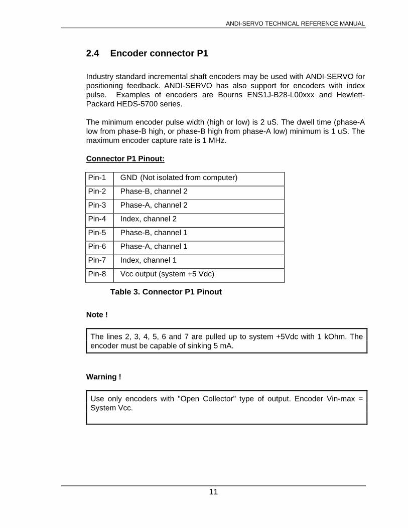
2.4 Encoder connector P1
Industry standard incremental shaft encoders may be used with ANDI-SERVO forpositioning feedback. ANDI-SERVO has also support for encoders with indexpulse. Examples of encoders are Bourns ENS1J-B28-L00xxx and Hewlett-Packard HEDS-5700 series.
The minimum encoder pulse width (high or low) is 2 uS. The dwell time (phase-Alow from phase-B high, or phase-B high from phase-A low) minimum is 1 uS. Themaximum encoder capture rate is 1 MHz.
Connector P1 Pinout:
Pin-1 GND (Not isolated from computer)
Pin-2 Phase-B, channel 2
Pin-3 Phase-A, channel 2
Pin-4 Index, channel 2
Pin-5 Phase-B, channel 1
Pin-6 Phase-A, channel 1
Pin-7 Index, channel 1
Pin-8 Vcc output (system +5 Vdc)
Table 3. Connector P1 Pinout
Note !
The lines 2, 3, 4, 5, 6 and 7 are pulled up to system +5Vdc with 1 kOhm. Theencoder must be capable of sinking 5 mA.
Warning !
Use only encoders with "Open Collector" type of output. Encoder Vin-max =System Vcc.

ANDI-SERVO TECHNICAL REFERENCE MANUAL
12
2.5 Auxiliary PWM-output connector P2
If the motor driver circuitry on the ANDI-SERVO is not capable of sourcingenough current to the motor, it is possible to utilize the motor-controller processorpart of the board and connect an external, and more powerful H-bridge to the P2connector. This connector outputs 8-bit sign/magnitude PWM of TTL-level.
PWM-output connector P2:
Pin-1 GND (not isolated from system)
Pin-2 Thermal flag input, channel 1
Pin-3 Thermal flag input, channel 2
Pin-4 Brake output, channel 2
Pin-5 Brake output, channel 1
Pin-6 Direction output, channel 2
Pin-7 PWM-output, channel 2
Pin-8 Direction output, channel 1
Pin-9 PWM-output, channel 1
Pin-10 GND (not isolated from system)
Table 4. PWM-output connector P2
Caution !
All signals are TTL-level.
Warning !
The thermal flag inputs are pulled to Vcc (system +5Vdc) by 1 kOhm. An "opencollector" type of device capable of sinking 5 mA is the only allowed type ofsignal source.
ANDI-SERVO TECHNICAL REFERENCE MANUAL
13
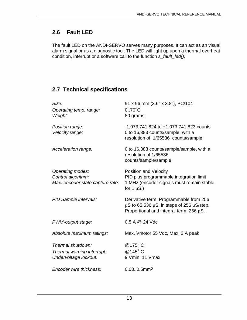
2.6 Fault LED
The fault LED on the ANDI-SERVO serves many purposes. It can act as an visualalarm signal or as a diagnostic tool. The LED will light up upon a thermal overheatcondition, interrupt or a software call to the function s_fault_led();
2.7 Technical specifications
Size: 91 x 96 mm (3.6" x 3.8"), PC/104Operating temp. range: 0..70°CWeight: 80 grams
Position range: -1,073,741,824 to +1,073,741,823 countsVelocity range: 0 to 16,383 counts/sample, with a
resolution of 1/65536 counts/sample
Acceleration range: 0 to 16,383 counts/sample/sample, with a resolution of 1/65536counts/sample/sample.
Operating modes: Position and VelocityControl algorithm: PID plus programmable integration limitMax. encoder state capture rate: 1 MHz (encoder signals must remain stable
for 1 µS.)
PID Sample intervals: Derivative term: Programmable from 256 µS to 65,536 µS, in steps of 256 µS/step. Proportional and integral term: 256 µS.
PWM-output stage: 0.5 A @ 24 Vdc
Absolute maximum ratings: Max. Vmotor 55 Vdc, Max. 3 A peak
Thermal shutdown: @175° CThermal warning interrupt: @145° CUndervoltage lockout: 9 Vmin, 11 Vmax
Encoder wire thickness: 0.08..0.5mm2

ANDI-SERVO TECHNICAL REFERENCE MANUAL
14
2.8 Board Layout
1 P 1
1
P3 P2
ANDI-SERVO 1
8
FAULT
LED 43210 765432
BASE IRQ
Figure 1. ANDI-SERVO Board Layout

ANDI-SERVO TECHNICAL REFERENCE MANUAL
15
2.9 Connector Locations
Figure 2. ANDI-SERVO connector locations

ANDI-SERVO TECHNICAL REFERENCE MANUAL
16
2.10 Block Diagram
Figure 3. Block Diagram of ANDI-SERVO v1.1

ANDI-SERVO TECHNICAL REFERENCE MANUAL
17
CHAPTER 3
3 FUNCTIONAL DESCRIPTIONLM629 PRECISION MOTION CONTROLLER
3.1 General Description
The LM629 is a dedicated motion-control processor designed for use with avariety of DC and brushless DC servo motors, and other servomechanismswhich provide a quadrature incremental position feedback signal. The partperform the intensive, real-time computational tasks required for highperformance digital motion control. The host control software interface isfacilitated by a high-level command set in the ANDI-SERVO library.
3.2 Features
• 32-bit position, velocity, and acceleration registers• Programmable digital PID filter with 16-bit coefficients• Programmable derivative sampling interval• Internal trapezoidal velocity profile generator• Velocity, target position, and filter parameters may be changed during motion• Position and velocity modes of operation• Real-time programmable host interrupts• Quadrature incremental encoder interface with index pulse input

ANDI-SERVO TECHNICAL REFERENCE MANUAL
18
3.3 Theory of Operation
3.3.1 Introduction
The typical system block diagram (See Figure 3, ANDI-SERVO Block Diagram)illustrates a servo system built using the LM629. The host processorcommunicates with the LM629 through an I/O port to facilitate programming atrapezoidal velocity profile on a digital compensation filter. The PWM outputinterfaces to an external PWM Hbridge that produces the signal that drives themotor. An incremental encoder provides feedback for closing the position servoloop. The trapezoidal velocity profile generator calculates the requiredtrajectory for either position or velocity mode of operation. In operation, theLM629 subtracts the actual position (feedback position) from the desiredposition (profile generator position), and the resulting position error isprocessed by the digital filter to drive the motor to the desired position. Table Iprovides a brief summary of specifications offered by the LM629:
3.3.2 Position feedback interface
The LM629 interfaces to a motor via an incremental encoder. Three inputs areprovided: two quadrature signal inputs, and an index pulse input. Thequadrature signals are used to keep track of the absolute position of the motor.Each time a logic transition occurs at one of the quadrature inputs, the LM629internal position register is incremented or decremented accordingly. Thisprovides four times the resolution over the number of lines provided by theencoder. Each of the encoder signal inputs is synchronized with the LM629clock.
The optional index pulse output provided by some encoders assumes the logic-low state once per revolution. If the LM629 is so programmed by the user, it willrecord the absolute motor position in a dedicated register (the index register) atthe time when all three encoder inputs are logic low.
If the encoder does not provide an index output, the LM629 index input canalso be used to record the home position of the motor. In this case, typically,the motor will close a switch which is arranged to cause a logic-low level at theindex input, and the LM629 will record motor position in the index register andalert (interrupt) the host processor. Permanently grounding the index input willcause the LM629 to malfunction.

ANDI-SERVO TECHNICAL REFERENCE MANUAL
19
3.3.3 Velocity profile (trajectory) generation
The trapezoidal velocity profile generator computes the desired position of themotor versus time. In the position mode of operation, the host processorspecifies acceleration, maximum velocity, and final position. The LM629 usesthis information to affect the move by accelerating as specified until themaximum velocity is reached or until deceleration must begin to stop at thespecified final position. The deceleration rate is equal to the acceleration rate.At any time during the move the maximum velocity and/or the target positionmay be changed, and the motor will accelerate or decelerate accordingly.
When operating in the velocity mode, the motor accelerates to the specifiedvelocity at the specified acceleration rate and maintains the specified velocityuntil commanded to stop. The velocity is maintained by advancing the desiredposition at a constant rate. If there are disturbances to the motion duringvelocity mode operation, the long-time average velocity remains constant. If themotor is unable to maintain the specified velocity (which could be caused by alocker rotor, for example), the desired position will continue to be increased,resulting an a very large position error. If this condition goes undetected, andthe impeding force on the motor is subsequently released, the motor couldreach a very high velocity in order to catch up to the desired position ( which isstill advancing as specified).
All trajectory parameters are 32-bit values. Position is a signed quantity.Acceleration and velocity are specified as 16-bit, positive-only integers having16-bit fractions. The integer portion of velocity specifies how many countsprovide increased average velocity resolution. Acceleration is treated in thesame manner. With each sampling interval the commanded acceleration valueis added to the current desired velocity (unless the command velocity has beenreached).

ANDI-SERVO TECHNICAL REFERENCE MANUAL
20
One determines the trajectory parameters for a desired move as follows. If, forexample, one has a 500-line shaft encoder, desired that the motor acceleratesat one revolution per second until it is moving at 600 rpm, and then decelerateto a stop at a position exactly 100 revolutions from the start, one wouldcalculate the trajectory parameters as follows:
let P = target position (units = encoder counts)let R = encoder lines * 4 (system resolution)then R = 500 * 4 = 2000and P = 2000 * desired number of revolutions P = 2000 * 100 revs = 200,000 counts ( value to load) P (coding) = 00030D40 (hex code written to LM629)
let V = velocity (units = counts/sample)let T = sample time (seconds) = 341 s
(with 6 MHz clock)let C = conversion factor = 1 minute/60 secondsthen V = R * T * C * desired rpmand V = 2000* 341E-6 * 1/60 * 600 rpm V = 6.82 counts /sample V (scaled) = 6.82 * 65,536 = 446,955.52 V (rounded) = 446,956 (value to load) V (coding) = 0006D1EC (hex written to LM629)
let A = acceleration (units = counts/sample/sample) A = R * T * T * desired acceleration (rev/sec/sec)then A = 2000 * 341E-6 * 341E-6 * 1 rev/sec/secand A = 2.33E-4 counts/sample/sample A (scaled) = 2.33E-4 * 65,536 = 15.24 A (rounded) = 15 (value to load) A (coding) = 0000000F (hex code written to LM629)
The above position, velocity, and acceleration values must be converted tobinary codes to be loaded into the LM629. The values shown for velocity andacceleration must be multiplied by 65,536 (as shown) to adjust for the requiredinteger/fraction format of the input data. Note that after scaling the velocity andacceleration values, literal fractional data cannot be loaded; the data must berounded and converted to binary. The factor of four increases in systemresolution is due to the method used to decode the quadrature encoder signals.

ANDI-SERVO TECHNICAL REFERENCE MANUAL
21
3.3.4 PID compensation filter
The LM629 uses a digital Proportional Integral Derivative (PID) filter tocompensate for the control loop. The motor is held at the desired position byapplying a restoring force to the motor that is proportional to the position error,plus the integral of the error, plus the derivative of the error. The followingdiscrete-time equation illustrates the control performed by the LM629:
n
u(n) = kp*e(n) + ki Σ e(n) +
N=0
kd[e(n’) - e(n’ - 1)]
where u(n) is the motor control signal output at sample time n, e(n) is the position error at sample time n, n’ indi- cates sampling at the derivative sampling rate, and kp, ki and kd are the discrete-time filter parameters loaded by the users.
The first term, the proportional term, provides a restoring force proportional tothe position error, just as does a spring obeying Hooke’s law. The second term,the integration term, provides a restoring force that grows with time, and thusensures that the static position error is zero. If there is a constant torqueloading, the motor will still be able to achieve zero position error.
The third term, the derivative term, provides a force proportional to the rate ofchange of position error. It acts just like viscous damping in a damped springand mass system (like a shock absorber in a automobile). The samplinginterval associated with the derivative term is user-selectable; this capabilityenables the LM629 to control a wide range of inertial loads (system mechanicaltime constants) by providing a better approximation of the continuousderivative. In general, longer sampling intervals are useful for low-velocityoperations.

ANDI-SERVO TECHNICAL REFERENCE MANUAL
22
(PID compensation filter....)
In operation, the filter algorithm receives a 16-bit error signal from the loopsumming-junction. The error signal is saturated at 16 bits to ensure predictablebehavior. In addition to being multiplied by filter coefficient kp, the error signalis added to an accumulation of previous errors (to form the internal signal) and,at a rate determined by the chosen derivative sampling interval, the previouserror is subtracted from it (to form the derivative signal). All filter multiplicationsare 16-bit operations; only the bottom 16 bits of the product are used.
The integral signal is maintained to 24 bits, but only the top 16 bits are used.the scaling techniques results in a more usable (less sensitive) range ofcoefficient ki values. The 16 bits are right-shifted eight positions and multipliedby filter coefficient ki to form the term which contributes to the motor controloutput. The absolute magnitude of this product is compared to coefficient il,and the lesser, appropriately signed magnitude then contributes to the motorcontrol signal.
The derivative signal is multiplied by coefficient kd each derivative samplinginterval. This product contributes to the motor control output every sampleinterval, independent of the user-chosen derivative sampling interval.
The kp, limited ki, and kd product terms are summed to form a 16-bit quantity.Depending on the output mode (wordsize), either the top 8 or top 12 bitsbecome the motor control output signal.

ANDI-SERVO TECHNICAL REFERENCE MANUAL
23
3.4 Typical Applications
3.4.1 Programming LM629 Host Handshaking (Interrupts)
A few words regarding the LM629 host handshaking will be helpful to thesystem programmer. As indicated in various portions of the above text, theLM629 handshakes with the host computer in two ways: via the host interruptoutput (Pin 17), or via polling the status byte for “interrupt“ conditions. Whenthe hardwired interrupt is used, the status byte is also read and parsed todetermine which of six possible conditions caused the interrupt.
When using the hardwired interrupt it is very important that the host interruptservice routine does not interfere with a command sequence which might havebeen in progress when the interrupt occurred. If the host interrupt serviceroutine were to issue a command to the LM629 while it is in the middle of anongoing command sequence, the ongoing command will be aborted (whichcould be detrimental to the application).
Two approaches exist for avoiding this problem. If one is using hardwiredinterrupts, they should be disabled at the host prior to issuing any LM629command sequence, and re-enabled after each command sequence. Thesecond approach is to avoid hardwired interrupts and poll the LM629 statusbyte for “interrupt“ status. The status byte always reflects the interrupt-conditionstatus, independent of whether or not the interrupts have been masked.
3.4.2 Incremental Encoder Interface
The incremental (position feedback) encoder interface consists of three lines:Phase A, Phase B, and Index. The index pulse output is not available onsome encoders. The LM629 will work with both encoder types.

ANDI-SERVO TECHNICAL REFERENCE MANUAL
24
3.4.3 I/O port usage (I/O map)
ANDI-SERVO occupies 8 contiguous I/O addresses, base+0 through base+7.The I/O port usage is as follows:
PORTADDRESS
FUNCTION ATREAD
FUNCTION ATWRITE
NOTES
base+0 Status byte Command byte from/toLM629,channel 1
base+1 Data byte Data byte -"-
base+2 Status byte Command byte from/toLM629,channel 2
base+3 Data byte Data byte -"-
base+4 No op PWM-Brakes bit-1=chan2,bit-0=chan1
base+5 No op Hardware Reset bit-1=chan2,bit-0=chan1
base+6 IRQ-cause Ena/Dis IRQ, LED See notes *)
base+7 Clear IRQ No op See notes **)
*) When written to: This register is used for hardware enabling/disabling theinterrupts and controlling the FAULT LED. If bit-1 is set to '1' , interrupts areenabled, otherwise disabled. If bit-0 is set to '1', the LED will be ON, otherwiseOFF.
When read: This register’s lowest four bytes indicate the source of the interrupt.The register can also be occasionally polled, to check for an overheat condition,for example. The register decodes as follows:
Bit-3 = '1' = Interrupt from LM629, channel 2Bit-2 = '1' = Interrupt from LM629, channel 1Bit-1 = '1' = Thermal overheat interrupt from channel 2Bit-0 = '1' = Thermal overheat interrupt from channel 1
**) The interrupt is held high until the Clear-IRQ register is read. This register doesnot return a value, it clears the interrupt condition.

ANDI-SERVO TECHNICAL REFERENCE MANUAL
25
4 SOFTWARE FUNCTIONS
Please refer to the attached software diskette for the latest library and examplecode. The functions herein are listed only to give a quick perception on what’sincluded in the library code.
s_check_busy(int chip)s_clr_irq(int chip, int mask) s_disable_irq(void)s_enable_irq(void)s_fault_led(int mode)s_get_base(void) s_get_bp_abs(int chip, long *bp)s_get_bp_rel(int chip, long *bp)s_get_brake(int chip, int *mode) s_get_desiredpos(int chip, long *pos)s_get_desiredvel(int chip, long *vel)s_get_errcode(void)s_get_indexpos(int chip, long *pos)s_get_integrsum(int chip, int *sum)s_get_irqmask(int chip, int *mask)s_get_poserr(int chip, int *trsh)s_get_realpos(int chip, long *pos)s_get_realvel(int chip, long *vel)s_get_signals(int chip, uint *s)s_get_status(int chip, int *stat)s_get_stoperr(int chip, int *trsh)s_init(int chip)s_pgm_filter(int chip, S_FILTERfl)s_pgm_trajectory(int chip, S_TRY tr)s_reset(int chip, int mode)s_set base(int base)s_set_absacc(int chip, long acc)s_set_abspos(int chip, long pos)s_set_absvel(int chip, long vel)s_set_bp_abs(int chip, long bp)s_set_bp_rel(int chip, long bp)s_set_brake(int chip,int mode)s_set_homepos(int chip)s_set_indexpos(int chip)s_set_irqmask(int chip, int mask)s_set_poserr(int chip, int trsh)s_set_stoperr(int chip, int trsh)s_soft_reset(int chip)s_start(int chip)s_stop(int chip, int mode)s_update_filter(int chip)
* end of document *


