NICC DSL Task Group Specification of the Specification of the Specification of the Specification of the Access Network Frequency Plan Access Network Frequency Plan Access Network Frequency Plan Access Network Frequency Plan applicable to transmission applicable to transmission applicable to transmission applicable to transmission systems systems systems systems used on the BT Access Network used on the BT Access Network used on the BT Access Network used on the BT Access Network Oftel Technical Requirement OTR004:2000 Issue 1.1 Approved November 2000
Transcript
NICC DSL Task Group
Specification of theSpecification of theSpecification of theSpecification of the
Access Network Frequency PlanAccess Network Frequency PlanAccess Network Frequency PlanAccess Network Frequency Plan
applicable to transmissionapplicable to transmissionapplicable to transmissionapplicable to transmission
systemssystemssystemssystems
used on the BT Access Networkused on the BT Access Networkused on the BT Access Networkused on the BT Access Network
Oftel Technical RequirementOTR004:2000 Issue 1.1
Approved November 2000
ANFP for the BT Access Network OTR004:2000 Issue 1.1
Annex 2 - ANFP Laboratory Test Specification ....................................................................................13
Annex 3 - ANFP Field Test Specification..............................................................................................22
Annex 4 - ANFP User Guide..................................................................................................................23
Annex 5 – ANFP History & Background...............................................................................................29
Annex 6 – ANFP Change Control Procedure.........................................................................................33
Foreword
This document has been produced by the NICC Task Group on Digital Subscriber Line (DSL) –Spectrum Management Plan. Network Operators, switch and terminal equipment manufacturers, testlaboratories, DTI (CII and RA), and OFTEL participated in the Task Group.
ANFP for the BT Access Network OTR004:2000 Issue 1.1
NICC DSL Task Group Page 3 of 33
1 Scope
This specification defines the Access Network Frequency Plan (ANFP) applicable to transmissionsystems to be used on the BT access network. It is applicable to the whole of the BT access networkprovided using unscreened twisted metallic pairs (e.g. it does not apply to the access network providedby optical fibre).
To ensure the prevention of undue interference between transmission systems used on differentmetallic pairs in the same access cable, transmission systems (whether provided by BT, OLO orcustomer) connected to metallic pairs of the BT access network need to conform to this specification.
This specification is applicable to all BT switched and leased line analogue services, and to OLOsusing the BT access network as defined in condition 83 of the public telecommunications operator’slicense issued to BT [13].
The limits specified in the ANFP apply when measured according to the associated referencemeasurement technique given in Annex 2.
This issue of this specification considers access to frequencies up to 1.1 MHz (e.g. for systems up toand including ADSL). The use of frequencies above 1.1 MHz has yet to be allocated and thisspecification restricts the use of these frequencies in order to protect their allocation later. It is plannedthat a future issue of the specification will be produced to use frequencies above 1.1 MHz (e.g. toinclude the use of VDSL).
It is recognised that a customer’s installation may comprise wiring and a number of items of CPE.Further, there may be other items of equipment between the customer’s installation and the metallicpair (i.e. on the network side of the NTP), e.g. filters or active line termination equipment. The limitsin this ANFP apply at the interface to the metallic pair of the BT access cable.
Where a customer’s installation causes, or can reasonably be foreseen to cause, harmful interference totransmission systems used on different metallic pairs in the same [or other] access cable[s], BT mayrequire that the interference be prevented, for instance by means of mitigation measures (e.g. by theaddition of a filter), or by requesting authorisation for disconnection under Article 7.4 of the RTTEdirective [6] or other relevant powers.
Note 1: Although, from a regulatory perspective, it is not a mandatory requirement for customerpremises equipment (CPE) to conform to this ANFP, since this would be contrary to theRTTE directive [6], it is strongly recommended that CPE does conform to this ANFP.
Note 2: This specification only considers the limits relevant to control of interference between DSLsystems on different lines. There may be other limits also applicable, and conformance tothis specification does not necessarily satisfy those limits. Such other limits may include, forexample, safety limits on line voltages, RFI balance requirements, line sharing limits, andPOTS band signals.
Note 3: Analogue leased lines and analogue POTS type functions of terminals may exceed the limitsstated in this ANFP in the frequency range 100 Hz to 5 kHz where they would otherwise beacceptable under the provisions of the UK implementation of the RTTE directive [6]. It isintended that future issues of the ANFP will provide a more detailed specification in thefrequency range 100 Hz to 5 kHz.
ANFP for the BT Access Network OTR004:2000 Issue 1.1
NICC DSL Task Group Page 4 of 33
2 ANFP Construction
The ANFP as specified in this document was developed as a result of the proposals defined in theOFTEL Access to Bandwidth statement (November 1999) [8]. The construction of the ANFP wasbased on the criteria:• set out in the OFTEL Access to Bandwidth statement• defined by the DSL Task Group.These criteria are documented in the ANFP User Guide (see Annex 4). This ANFP aligns with theOFTEL ANFP Determination (September 2000) [12].
In deciding the criteria to be used and the method of construction for the ANFP, the DSL Task Grouptook account of the work on this subject being undertaken in ANSI T1E1 [11] and ETSI TM6 [10].
The ANFP has been constructed using the following method:• the management of the ANFP will be by hard Power Spectrum Density (PSD) masks [7].• each interface giving access into the cable plant will have a PSD mask defined for it. Interfaces at
different locations may have different masks.• the mask will apply to any equipment connected at the location, irrespective of modem type1.• the mask will define the limit for power transmitted (or leaked) into the cable plant.• at each frequency, the PSD of the transmitter must be at or lower than the permitted PSD mask.
The permitted PSD masks are produced as follows:• The systems already deployed in significant volumes are identified2. These are taken as the
existing noise environment (any transmission system will be permitted to be used on the BT accessnetwork provided that it conforms to the ANFP masks).
• A PSD mask is produced for each transmitter of each identified system.• Locations are categorised according to which identified system transmitters may have been
installed there.• For each location category the permitted PSD mask is, at each frequency independently, the
maximum of the masks for those transmitters which may have been installed there.
This method of construction is consistent with the work so far undertaken in ETSI TM6. It derivesfrom the fact that the identified systems in the network have been deployed such that they will operatereliably in the presence of the crosstalk from other identified systems.
Any increase in the level of pollution that is permitted will directly result in decreased margin ofperformance in already deployed systems. Any substantial increase would cause these systems to fail.
1 Strictly the ANFP is applied to the point of connection, so applies even in the absence of anyequipment.
2 The xDSL systems that have been taken into account in this ANFP specification are ISDN basicaccess, 2-pair and 3-pair 2 Mbit/s 2B1Q HDSL systems, and ADSL over POTS. All deployed as perBT’s historical deployment rules. SDSL technology was also admitted, but limited to a selection ofrates with minimal impact on the ANFP masks.
ANFP for the BT Access Network OTR004:2000 Issue 1.1
NICC DSL Task Group Page 5 of 33
It should be noted that the ANFP is constructed with masks that are more realistic than those in currentequipment standards. The equipment standards typically have a generous margin between what asystem is limited to and what a real system actually produces, so a good implementation passes thestandard easily. However some real systems already deployed would fail if their neighbours were tofully exploit a mask based on the equipment standards’ masks. It has been necessary to use masksfrom FSAN3 for the identified systems’ transmitters. However every effort has been made to enablethe deployment of the maximum variety of future DSL systems where this can be done without impactto the identified systems.
3 Full Services Access Networks – a group of network operators and suppliers who co-operate indriving standards work towards specifying equipment that is usable by operators.
ANFP for the BT Access Network OTR004:2000 Issue 1.1
NICC DSL T
3 ANFP Specification
The ANFP is currently defined by a set of four PSDs.
mask name defines PSD permitted at:
down exch the MDF of the exchange
up short the NTP of near customers
up medium the NTP of mid distance customers
up long the NTP of far customers
Mask ‘down exch’ is a downstream mask, for lines toward the customers. It is the only downstreammask currently defined. The other three masks are upstream masks, for lines toward the exchange.
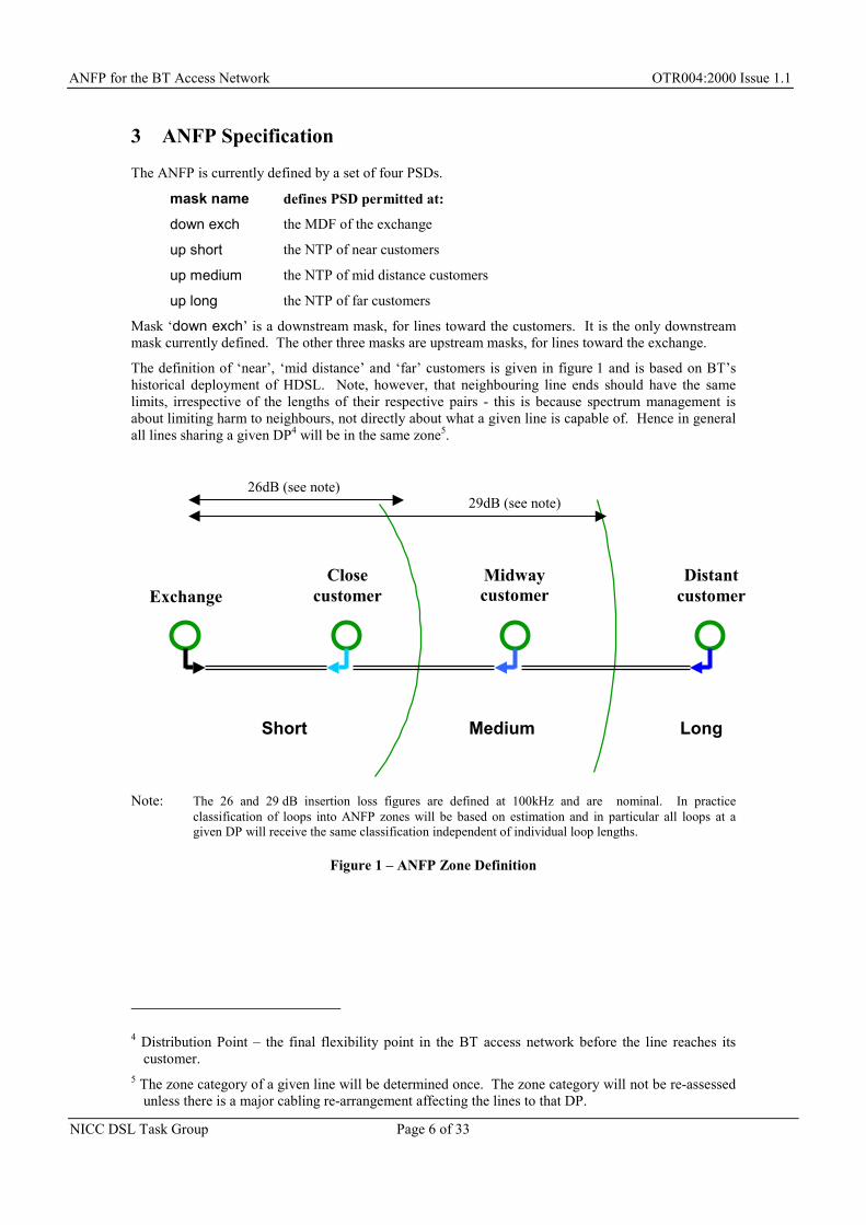
The definition of ‘near’, ‘mid distance’ and ‘far’ customers is given in figure 1 and is based on BT’shistorical deployment of HDSL. Note, however, that neighbouring line ends should have the samelimits, irrespective of the lengths of their respective pairs - this is because spectrum management isabout limiting harm to neighbours, not directly about what a given line is capable of. Hence in generalall lines sharing a given DP4 will be in the same zone5.
N 26 an on loss figures are defi and are nominal. In pra ticeification of lo s into ANFP zones will be ba n and in particular all loops at an DP will recei the same classification independe dual loop lengths.
Figure 1 – ANFP Zone D
4
5 T
elosetomer
Distantcustomer
Long
2)
ote: The classgive
Exchang
ask Group Page 6 of 33
Distribution Point – the f al flexibility point in the BT customer.
he zone category of a given line will be determined once.unless there is a major cabling re-arrangement affecting the
at 100kH on estimant of indivi
efinition
Midwayustomer
edium
acc network before the line reache its
T li
ess
opve
in
rt
he zone category will not be re-assenes to that DP.
c
s
ned z sed tio
c
M
9dB (see note)
d 29 dB inserti
Ccus
Sho
26dB (see note
ssed
ANFP for the BT Access Network OTR004:2000 Issue 1.1
NICC DSL Task Group Page 7 of 33
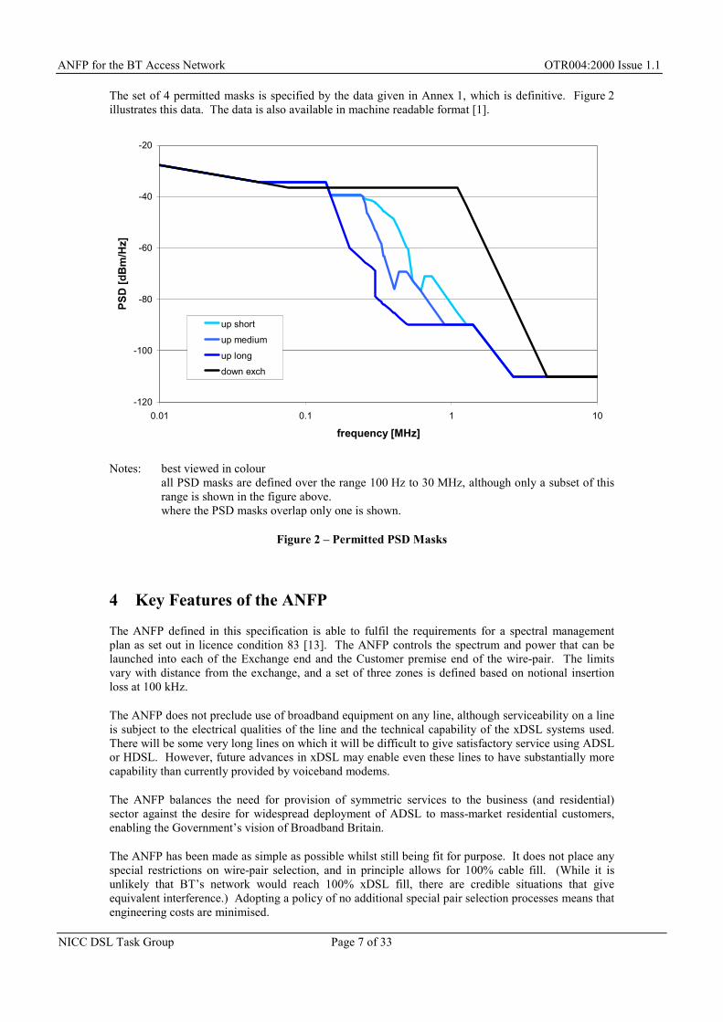
The set of 4 permitted masks is specified by the data given in Annex 1, which is definitive. Figure 2illustrates this data. The data is also available in machine readable format [1].
-120
-100
-80
-60
-40
-20
0.01 0.1 1 10
frequency [MHz]
PSD
[dB
m/H
z]
up shortup medium
up longdown exch
Notes: best viewed in colourall PSD masks are defined over the range 100 Hz to 30 MHz, although only a subset of thisrange is shown in the figure above.where the PSD masks overlap only one is shown.
Figure 2 – Permitted PSD Masks
4 Key Features of the ANFP
The ANFP defined in this specification is able to fulfil the requirements for a spectral managementplan as set out in licence condition 83 [13]. The ANFP controls the spectrum and power that can belaunched into each of the Exchange end and the Customer premise end of the wire-pair. The limitsvary with distance from the exchange, and a set of three zones is defined based on notional insertionloss at 100 kHz.
The ANFP does not preclude use of broadband equipment on any line, although serviceability on a lineis subject to the electrical qualities of the line and the technical capability of the xDSL systems used.There will be some very long lines on which it will be difficult to give satisfactory service using ADSLor HDSL. However, future advances in xDSL may enable even these lines to have substantially morecapability than currently provided by voiceband modems.
The ANFP balances the need for provision of symmetric services to the business (and residential)sector against the desire for widespread deployment of ADSL to mass-market residential customers,enabling the Government’s vision of Broadband Britain.
The ANFP has been made as simple as possible whilst still being fit for purpose. It does not place anyspecial restrictions on wire-pair selection, and in principle allows for 100% cable fill. (While it isunlikely that BT’s network would reach 100% xDSL fill, there are credible situations that giveequivalent interference.) Adopting a policy of no additional special pair selection processes means thatengineering costs are minimised.
ANFP for the BT Access Network OTR004:2000 Issue 1.1
NICC DSL Task Group Page 8 of 33
The ANFP is technology neutral, and as such is as future proof as possible. The PSDs used in theANFP are consistent with the levels used by internationally standardised xDSL systems. Thisminimises the risk of introduction of rogue xDSL systems with strong line spectra that may causeobjectionable radiated emissions.
The potential use of SDSL systems (as currently being defined in ETSI TM6) has been factored intothe ANFP and will be permitted by the plan (the data rate that may be attempted by these SDSLsystems will be dependent on the zone of the customer’s end).
For further information on the features of the ANFP and guidance on conformance to the ANFP, seethe ANFP User Guide (Annex 4)
5 Future Development
A change control process for this specification has been agreed, see Annex 6.
As indicated in the scope, the Task Group already plans to increase the scope of the plan to coverfrequencies up to 30 MHz (i.e. to include VDSL). This change is not expected to impact existingsystems deployed in conformance to this issue of the ANFP.
6 Abbreviations
ADSL Asymmetric Digital Subscriber Line
ANFP Access Network Frequency Plan
ANSIANSI T1E1.4
American National Standards Institute
T1E1.4 is their working group concerned with DSLHomepage: http://www.t1.org/t1e1/_e14home.htm
BT British Telecommunications plc(bridged taps are not discussed in this document)
CPE Customer Premises Equipment
CSV Comma Separated Variable - a file format based on plain text, readable bymany common spreadsheet programs.
DP Distribution Point – the final flexibility point in the BT access network beforethe line reaches its customer
DSL Digital Subscriber Line - any of the modem technologies which send highspeed data over metallic telephone pairs. A DSL line has a dedicated modemat each end of the physical wire pair; typically one of these is in the exchange
DSL TG Digital Subscriber Line Task Group
A subcommittee of PNO-IG
ETSIETSI TM6
European Telecommunications Standards Institute
TM6 is the working group on Access NetworksHomepage: http://webapp.etsi.org/tbhomepage/TBDetails.asp?TB_ID=240
FSAN Full Services Access Networks – a group of network operators and supplierswho co-operate in driving standards work towards specifying equipment that isusable by operators
- a committee of UK industry set up to advise OFTELhomepage: http://www.oftel.gov.uk/NICC/
OLO Other Licensed Operator
NTP Network Termination Point
PBLC Partial Baseboard Leased Circuit
This term was used in [8] but subsequently changed to Metallic Path Facility inthe BT Licence Conditions
PNO-IG Public Network Operators Interest Group
- an interest group within NICC
POTS Plain Ordinary Telephone Service - analogue voiceband telephony
PSD Power Spectral Density - [7]
RFI Radio Frequency Interference
RTTE Radio and Telecommunications Terminal Equipment - [6]
SDSL Symmetric Digital Subscriber Line - in this document ‘SDSL’ refers to thattechnology currently being defined in ETSI TM6
VDSL Very high rate asymmetric Digital Subscriber Line
7 References
[0] “Specification of the Access Network Frequency Plan applicable to transmissionsystems used on the BT Access Network”Oftel Technical Requirement OTR004:2000 Issue 1.1available at URL http://www.oftel.gov.uk/NICC/Public/anfp_1_1.pdf
Self reference to give a holder of a paper copy access to the electronic version.
[1] ANFP PSD Mask Definitionsavailable at URL http://www.oftel.gov.uk/NICC/Public/anfpmask.csv
This is a machine readable form of the table in Annex 1. Read Annex 1 to interpret this data. Anydiscrepancies are errors, in which case Annex 1 is definitive.
[2] “Essential requirements for terminal equipment intended for Connection tounstructured digital leased circuits of the public Telecommunications network using aCCITT Recommendation G.703 interface at a rate of 2048 kbit/s with a 75 Ωunbalanced presentation”PD 7024: 1994available from BSI, see URL http://www.bsi-global.com/
ANFP for the BT Access Network OTR004:2000 Issue 1.1
NICC DSL Task Group Page 10 of 33
[3] EC, DIRECTORATE GENERAL XIII"Informal Consolidated Text of the ONP Framework Directive"10 June 1997may be downloaded from http://www.ispo.cec.be/infosoc/legreg/docs/90387ecrev.html
Editor: as at 01 Dec 2000 this hyperlink seems dead. A perennial risk of using URLs as references.
This is a preliminary version of the revised ONP framework directive, being directive 90/387/EC asamended by 97/51/EC.
[4] ADLNB WG-2 (chairman C. P. Raymont)"Guidance Notes on Measurement Uncertainty"GN/WG2/1 issue 3 dated 19 March 1998may be obtained from http://www.adlnb.com/
In the methods of [4] there is separation between requirements specification and the capabilities of anyparticular test house. ADLNB has recently been incorporated into a larger body, the “R&TTECompliance Association”
[5] EC"Directive 98/10/EC
of the European Parliament and of the Council of 26 February 1998on the application of open network provision (ONP) to voice telephony and on universalservice for telecommunications in a competitive environment "Official Journal of the European Communities : OJ L 101/24 of 1.4.98
This is the Revised Voice Telephony Directive (“RVTD”). The text may be downloaded fromhttp://www.ispo.cec.be/infosoc/telecompolicy/en/harmony.htm. Also of interest ishttp://www.dti.gov.uk/CII/rvtd/condoc.htm which sets out the UK Government's proposals forimplementing the RVTD.
[6] EC"Directive 99/5/EC
of the European Parliament and of the Council Relating to Radio Equipment andTelecommunications Terminal Equipment and the Mutual recognition of theirConformity"Official Journal of the European Communities : OJ L 91, Vol. 41 of 7th April 1999the full text may be downloaded from http://www.tapc.org.uk
The UK Statutory Instrument 2000 No 730 ("The RTTE Regulations") was published on 13 March2000. It transposes the provisions of the Directive into UK law. It is also available athttp://www.tapc.org.uk
[7] FSAN"Interpretation of PSD for PSD masks"TD 15 at the ETSI TM6 Meeting, Sophia Antipolis, 24-27 November, 1998
also presented to ANSI T1E1.4 as paper 98-327
[8] OFTEL"Access to Bandwidth: Delivering Competition for the Information Age"November 1999may be downloaded from http://www.oftel.gov.uk/competition/a2b1199.htm
[9] "General requirements for the competence of testing and calibration laboratories"ISO/IEC 17025: 1999
ANFP for the BT Access Network OTR004:2000 Issue 1.1
NICC DSL Task Group Page 11 of 33
[10] ETSI TM6"Part 1 : Definitions and Signals Library"Permanent Document TM6(99)07
This is the first product of the ETSI TM6 Spectral Management project
[11] ANSI T1E1.4"Spectrum Management For Loop Transmission Systems"T1E1.4/2000-002R3 DRAFT T1.XXX-2000may be downloaded from ftp://ftp.t1.org/pub/t1e1/e1.4/dir2000/0e140023.pdf
[12] OFTEL"Access to Bandwidth: Determination on the Access Network Frequency Plan (ANFP)for BT's Metallic Access Network"may be downloaded from http://www.oftel.gov.uk/competition/anfp1000.htm
[13] OFTEL"REQUIREMENT TO PROVIDE ACCESS NETWORK FACILITIES"April 2000may be downloaded from http://www.oftel.gov.uk/competition/acnf0400.htm
This is condition 83 of the public telecommunications operator’s license issued to BT by Oftel
8 Document History
Issue 1 First Issue, September 2000
Issue 1.1 Approved, November 2000.
The NICC Task Group on Digital Subscriber Line wishes to acknowledge its editors
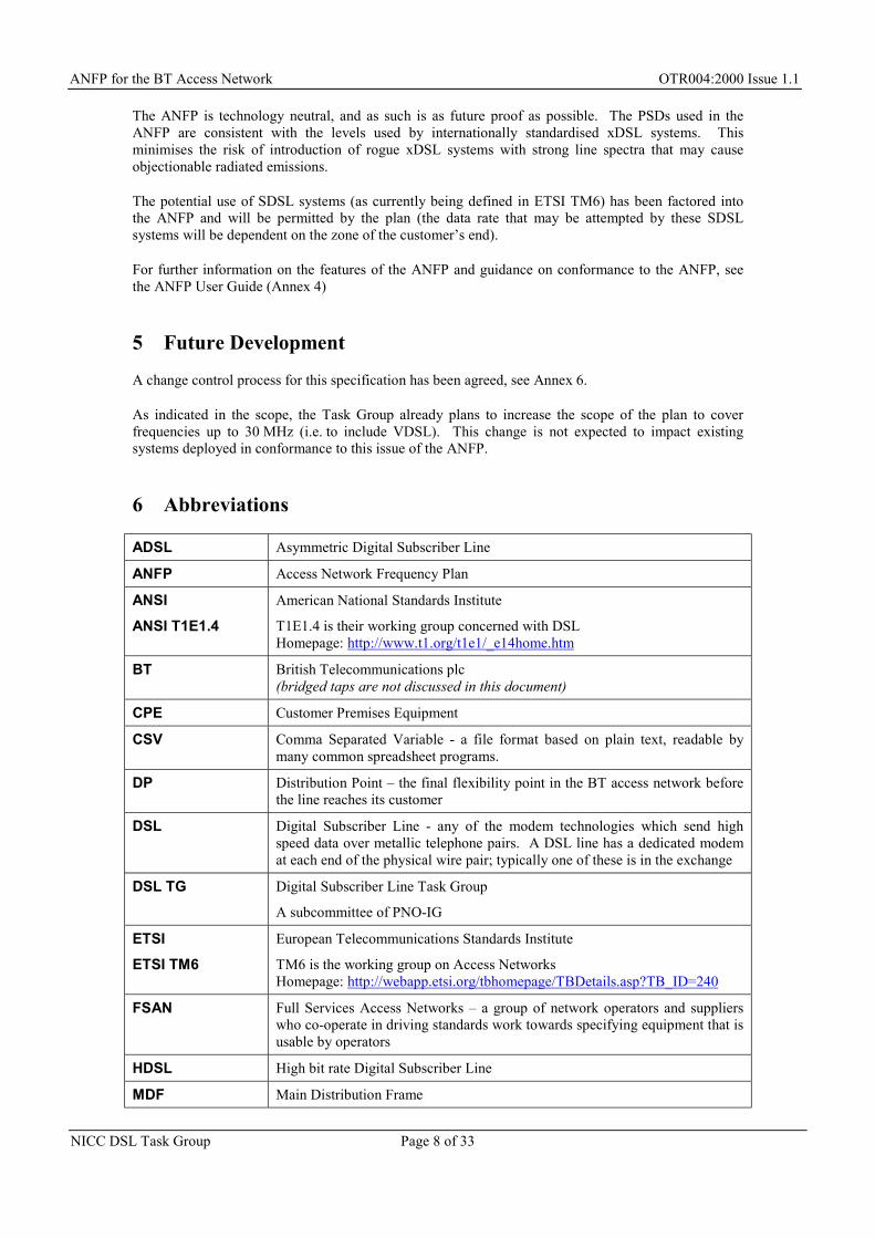
The masks are defined by the data given in this Annex. The tabulated data define the corners of eachmask. Between the given corners the mask values are defined by interpolation (as a straight line onlog frequency / linear dB axes). Frequency is in MHz; PSD is in dBm/Hz.
This data is also available in a machine readable format [1]. This version is made available to helpprevent input errors when performing modelling evaluation. Note that the CSV file contains "a" for theblank fields (to be interpolated) in the table below. This has been done to increase compatibility withsome applications which don't treat blank entries correctly.
6.1 PSD measurement procedure .............................................................................166.1.1 Test circuit for PSD measurement............................................................................................166.1.2 Calibration of the test circuit and termination impedance ........................................................186.1.3 Operation of the EUT ...............................................................................................................196.1.4 Power spectral density (PSD) measurement procedure............................................................196.1.4.1 PSD resolution bandwidth .....................................................................................................196.1.4.2 PSD Integration Time............................................................................................................20
A Informative Appendix : Nonstationary Signals ...............................................21
1 Scope
This test specification defines tests to be used in a laboratory environment to determine conformance oftelecommunications equipment to the requirements specified in the main body of the ANFP.
The tests here only relate to the requirements of the ANFP. Other limits, for example those related tosafety, line balance, and interactions between systems on the same pair are out of scope.
Note 1: As stated in the scope of the ANFP, Issue 1 of the ANFP specification considers frequenciesup to 1.1 MHz (e.g. for systems up to and including ADSL) and the specification restrictsthe use of higher frequencies in order to protect their future allocation. The NICC DSL TaskGroup plan a future issue of the ANFP specification to cover frequencies above 1.1 MHz(e.g. to include the use of VDSL). This Test Specification only covers Issue 1 of the ANFP.
Annex 2 - ANFP Laboratory Test Specification OTR004:2000 Issue 1.1
NICC DSL Task Group Page 14 of 33
Note 2: This test specification is for use in a laboratory environment only. The development of a testspecification for use in the field is the subject of on-going work in the DSL Task Group.
Note 3: Strictly the ANFP specifies limits at the ports of the access network, not for individualequipment per se. This specification is to verify that when deployed equipment would notviolate the ANFP.
Note 4: Section 5 of this document is based on the equivalent specification contained in the ANSISpectrum Management For Loop Transmission Systems standard [11]. The use andreproduction of extracts from that standard is provided with kind permission of ANSI(American National Standards Institute).
2 Reference Model
The ANFP limits the power that may be injected into a metallic pair in the BT access network at twointerfaces, the NTP6 at the customer premises, and the MDF7 at the exchange.
In the case of Local Loop Unbundling, there is a third interface, the HDF8. Managing crosstalkinterference in the cabling between the HDF and the MDF is the responsibility of the networkoperator(s) using that cabling. The ANFP is applied at the MDF.
Jumper, ortie cable
Accessnetwork pair
Customer’sbuildingwiring
Jumper, ortie cable
CPE
HDF MDF(measurehere)
NTP(measurehere)
networkequipment
Figure 3 : Network Interfaces to which the ANFP applies
3 Test Configuration
The equipment under test (“EUT”) will comprise theend equipment, any ancillaries which are alwayspresent9, and a load to represent the access network.
The equipment at each end is tested independently.
Equipment will be tested in all modes which theoperator proposes to use. Other modes, perhapsprovided for use in other countries, need not betested.
loadEUT
Minimalcable
measurehere
Figure 4 : Test configuration
6 “Network Termination Point”, is the legal demarcation between the network provider’s cabling andthe customer’s in-house wiring. On a telephone line this point often has a master socket or NTE(“Network Termination Equipment”).
7 “Main Distribution Frame”, is the equipment which terminates the access network cables.8 “Handover Distribution Frame”, is the equipment which terminates the tie cables.9 For example splitter filters, and connecting leads which are part of the kit supplied with the end
equipment
Annex 2 - ANFP Laboratory Test Specification OTR004:2000 Issue 1.1
NICC DSL Task Group Page 15 of 33
The limits applicable to each end vary depending where the end is. For exchange end equipment thereis one set of limits. For customer end equipment there are three, for locations at different distancesfrom the exchange. An end equipment shall be tested against all the limits applicable to those placeswhere it is proposed to be deployed.
4 Measurement Conditions
The prospective operator shall declare his deployment intentions for the equipment under test. Thisdetermines which modes the equipment is tested in, and which ANFP mask(s) it is tested against.
The measurement conditions below are derived from ISO/IEC 17025 [9], "Guidance Notes onMeasurement Uncertainty" [4], and PD 7024 [2]
4.1 Estimation of uncertainty of measurement
A laboratory or facility performing testing shall have and shall apply procedures for estimatinguncertainty of measurement.
When estimating the uncertainty of measurement, all uncertainty components which are of importancein a given situation shall be taken into account using appropriate methods of analysis.
The test report or compliance statement shall include the uncertainty of measurement.
Note: 1 It is recommended that measurement uncertainty is calculated as defined in [4]
Note: 2 Sources contributing to uncertainty include, but are not necessarily limited to, the referencestandards and reference materials used, methods and equipment used, properties andcondition of the item being tested.
4.2 Compliance
Compliance to the requirements of this standard shall be reported on the shared risk principle asspecified in [4] figures 1 to 3.
Compliance to these requirements shall be determined either by use of the test methods defined withinthis standard or by use of test methods and results obtained from other standards accompanied with atechnical justification detailing how such results demonstrate compliance to this standard.
Note: Since the requirements of this standard are derived from a number of technology specificstandards in many cases it will be sufficient to test equipment to the specific design standardfor their technology , and make a compliance statement to this standard following technicalreview of the results. The technical review should not be omitted as some options ofspecific technologies are excluded from these requirements and would present non-compliant results to this standard.
4.3 Calibration of test equipment
Equipment and its software used for testing shall be capable of achieving the accuracy required.Calibration programs shall be established for values of the instruments where these properties have asignificant effect on the result
The equipment shall be calibrated to provide a 95% confidence level in the accuracy of the results.
Annex 2 - ANFP Laboratory Test Specification OTR004:2000 Issue 1.1
NICC DSL Task Group Page 16 of 33
4.4 General Conditions for Test
If the supplier has specified a temperature range within which the TE will be operational, the testingshall be performed within this range. The testing shall be performed within the temperature range15 ºC to 25 ºC, if consistent with the temperature range declared by the supplier.
If the supplier has specified a humidity range within which the TE will be operational, the testing shallbe performed within this range. The testing shall be performed within the humidity range 45% to 75%,if consistent with the humidity range declared by the supplier.
For equipment that is directly powered from the mains supply all tests shall be carried out within ±5%of the normal operating voltage.
If the equipment is powered by other means and those means are not supplied as part of the equipment,(e.g. batteries, stabilized AC supplies, DC) all tests shall be carried out within the power supply limitdeclared by the supplier.
If the power supply is AC the tests shall be conducted within ±4% of the stated frequency as declaredby the supplier.
4.5 Independence of polarity
The equipment shall conform independent of the polarity of the pair it uses. For a line powered EUTthe tests shall be carried out twice, once with each polarity of connection of the power supply.
5 Conformance testing methodology below 5 kHz
No formal tests are currently specified here.
Note: The absence of tests here should not be interpreted as license : the ANFP does set limitsbelow 5 kHz. Conformance testing methodology is for further study.
6 Conformance testing methodology above 5 kHz
The conformance testing methodology in this clause is derived from "Spectrum Management For LoopTransmission Systems" [11]. It shall be used to determine compliance with the signal powerlimitations requirements in the ANFP.
Note: Where the ANFP, Issue 1 makes no requirements (e.g. longitudinal output, nonstationarysignals), this annex specifies no tests.
6.1 PSD measurement procedure
The limits applicable to a particular end equipment are discussed above, in section 4.2.
6.1.1 Test circuit for PSD measurement
A test set-up as pictorially shown in figure 5 shall be used for measuring PSD. Examples of specificembodiments of this test set-up are shown in figures 6 and 7. The difference between figures 6 and 7 isthe input impedance of the instrument to be connected to Vout; figure 6 assumes a high-impedance port,figure 7 assumes a 50 Ω port (typical for a spectrum analyzer). The PSD may be tested while linepowered or locally powered as required by the intended application of the EUT.
Annex 2 - ANFP Laboratory Test Specification OTR004:2000 Issue 1.1
NICC DSL Task Group Page 17 of 33
Equipmentunder test (EUT)
Return lossas per calibrationof the test circuit
1 uF (min)
1 uF (min)
Vout
DCcurrent
sink
ResistiveTermination, R Ohms
(ground isolatedinput)
Figure 5 - PSD measurement set-up
R
1:1(+/- 1%)
(To high-impedance
load)
Vout
Equipmentunder test (EUT)
Return lossas per calibrationof the test circuit
1 uF (min)
1 uF (min)
DCcurrent
sink
Figure 6 - Example PSD measurement set-up for high impedance instrument
√50Ω:√R(± 1%)
(To 50 Ωinstrument
port)
Vout
Equipmentunder test (EUT)
1 uF (min)
1 uF (min)
DCcurrent
sink
Return lossas per calibration
of the test circuit
Figure 7 - Example PSD measurement set-up for 50 ohm instrument
If the EUT neither sources nor sinks power the blocking capacitors may be omitted, as may the currentsink. If present the capacitors shall be matched in value to within 1%.
If the EUT is line powered then the test circuit shall contain provisions for DC power feed, instead ofthe current sink.
For line powered applications, if the EUT is a TU-C the test shall be performed with the line powersupply activated and an appropriate DC current sink (with high AC impedance) attached to the testcircuit. If the EUT is a TU-R the test shall be performed with power (DC voltage) applied at the lineinterface by an external voltage source feeding through an AC blocking impedance. Note that the DCcurrent source/sink must present high impedance (at signal frequencies) to common ground. The testcircuit contains provisions for transformer isolation for the measurement instrumentation. Transformerisolation of the instrumentation input prevents measurement errors from unintentional circuit pathsthrough the common ground of the instrumentation and the EUT power feed circuitry. When thetermination impedance of the test circuit seen by the EUT output meets the calibration requirementsdefined in 4.3 the test circuit will not introduce more than ± 0.25 dB error with respect to a perfect testload of exactly the specified resistance.
Annex 2 - ANFP Laboratory Test Specification OTR004:2000 Issue 1.1
NICC DSL Task Group Page 18 of 33
If the EUT is supplied with a voiceband splitter filter10 then the tests shall be carried out with thesplitter in circuit but with no voiceband signal applied. Where the splitter has a connector for thevoiceband connection, this shall be open circuit during tests. Where voiceband equipment is integratedwith the splitter this equipment shall be quiescent during tests.
The EUT shall be measured by equipment that is not synchronous with the transmitted symbols of theEUT, and there shall be no synchronization between the measurement equipment and the EUT. This isto avoid any cyclo-stationarity effects causing a misleading measurement.
6.1.2 Calibration of the test circuit and termination impedance
The nominal termination impedance of the test circuit as seen by the EUT output shall be resistive witha resistance of R between 100 Ω and 135 Ω. If the EUT has been designed to a published standard thenthe resistive impedance specified in that standard shall be used (providing it is between 100 Ω and135 Ω). The minimum return loss with respect to the termination impedance R shall be 35 dB from10 kHz to 2 MHz with a reduction of 20 dB/decade below and above these corner frequencies.
-10
0
10
20
30
40
0.1 1 10 100 1000 10000 100000
frequency [kHz]
retu
rn lo
ss [d
B]
Figure 8 – Return loss mask
Figure 8 shows the return loss mask. The test circuit must exhibit this loss or higher at all frequencies.
Note 1: No passive circuit can exhibit a negative return loss, so calibration has implied limits on thefrequency band to be measured over.
Note 2: 35 dB return loss will allow ±0.20 dB measurement error with respect to the nominaltermination impedance value, R.
10 e.g. to allow DSL and ordinary telephony to share the line
Annex 2 - ANFP Laboratory Test Specification OTR004:2000 Issue 1.1
NICC DSL Task Group Page 19 of 33
6.1.3 Operation of the EUT
The EUT shall be tested while it transmits maximum power and maximum PSD levels at all measuredfrequencies, which it can transmit data when deployed. The EUT shall have power cutback or boostconfigured to match the proposed deployment. The EUT shall be tested under steady state conditions,after all start-up and initialization procedures have been completed and while the EUT is transmittingdata. To ensure that the EUT is in a steady-state condition, while undergoing test the EUT shall nothave measured total average powers in distinct 1.25 millisecond time intervals that differ by more than8 dB. The EUT input shall consist of a pseudo-random uniformly distributed data sequence, and theEUT output shall be a fully modulated transmit signal with all overhead, framing, coding, scrambling,modulation, filtering and all other operations performed on the data stream that the modem wouldnormally perform while transmitting data.
Note: Although specific measurements of average power and PSD during start-up and other non-data transmission phases are not provided, a EUT that transmits inordinately high power orPSD levels during these phases may be considered to be in non-compliance with thisstandard.
6.1.4 Power spectral density (PSD) measurement procedure
6.1.4.1 PSD resolution bandwidth
The nominal frequency of a measurement will be the centre frequency of its resolution bandwidth.Instrument RBW shall be 10 kHz. Measurements will be at integer multiples of 10 kHz, starting at10 kHz, so the lowest frequency measurement will be nominally 10 kHz and actually a window from5 kHz to 15 kHz.
Inside the signal bands the measured values for each 10 kHz band shall be compared against the masksindividually. Outside the signal bands the measured values will be averaged in overlapping groups of100 10 kHz bands, to produce the effect of a 1 MHz RBW sliding window; the averaged values will becompared against the masks.
The mask value to be compared against shall be the maximum value the mask takes within the effectivewindow. (Typically the first few steps of the 1 MHz sliding window will be compared againstsubstantially higher values than the mask at the nominal centre frequency would suggest).
For the ANFP, Issue 1 masks this means:
Table 1 - Resolution bandwidth for measuring against the down exch mask
Frequency Band Resolution Bandwidth
5 kHz to 3095 kHz 10 kHz
3095 kHz to 30005 kHz 1 MHz
Table 2 - Resolution bandwidth for measuring against the up short mask
Frequency Band Resolution Bandwidth
5 kHz to 1265 kHz 10 kHz
1265 kHz to 30005 kHz 1 MHz
Annex 2 - ANFP Laboratory Test Specification OTR004:2000 Issue 1.1
NICC DSL Task Group Page 20 of 33
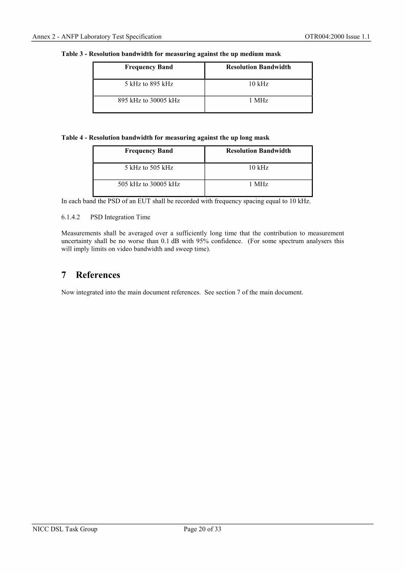
Table 3 - Resolution bandwidth for measuring against the up medium mask
Frequency Band Resolution Bandwidth
5 kHz to 895 kHz 10 kHz
895 kHz to 30005 kHz 1 MHz
Table 4 - Resolution bandwidth for measuring against the up long mask
Frequency Band Resolution Bandwidth
5 kHz to 505 kHz 10 kHz
505 kHz to 30005 kHz 1 MHz
In each band the PSD of an EUT shall be recorded with frequency spacing equal to 10 kHz.
6.1.4.2 PSD Integration Time
Measurements shall be averaged over a sufficiently long time that the contribution to measurementuncertainty shall be no worse than 0.1 dB with 95% confidence. (For some spectrum analysers thiswill imply limits on video bandwidth and sweep time).
7 References
Now integrated into the main document references. See section 7 of the main document.
Annex 2 - ANFP Laboratory Test Specification OTR004:2000 Issue 1.1
NICC DSL Task Group Page 21 of 33
A Informative Appendix : Nonstationary Signals
This appendix concerns equipment which only transmits power intermittently – typically when there isdata to send. The significant impact of such signals is due to their power when transmitting, not anaverage over all time.
It is technically difficult to specify how to measure intermittent signals, unless the equipment has acontinuous signal test mode (in which case it may be sufficient to conduct tests in that mode, as fornormal equipment). Furthermore, at time of writing there is little practical interest in deploying suchequipment under the ANFP. Therefore a normative laboratory test specification is not provided.
Note: The ANSI Spectrum Management specification [11] does specify some tests for suchsignals, in its section 6.4 “Short-term stationary conformance criteria”.
Annex 3 - ANFP Field Test Specification OTR004:2000 Issue 1.1
NICC DSL Task Group Page 22 of 33
Annex 3 - ANFP Field Test Specification
Not yet defined. The NICC DSL Task Group is studying this subject but it is not yetclear if and when such a specification will be available.
2 The ANFP for the UK.........................................................................................24
2.1 Line Categorisation ............................................................................................24
2.2 How the various classes of DSL may fit the ANFP ...........................................24
3 Ensuring equipment conforms to the ANFP ....................................................25
3.1 Enforcement on Network Operators...................................................................25
3.2 Enforcement on Customer Equipment ...............................................................26
3.3 Enforcement on Equipment installed prior to the publication of the ANFP ......26
4 Policing the ANFP...............................................................................................27
4.1 Why are policing measures needed? ..................................................................27
4.2 What is covered by the policing measures? .......................................................27
4.3 What type of policing measures is to be adopted? .............................................27
4.4 Outline of Code of Practice ................................................................................27
4.5 The need for co-operation ..................................................................................28
5 Evolution of the ANFP .......................................................................................28
1 Introduction
This user guide outlines the industry agreements reached to manage the connection of equipment to theBT copper access cables as part of the operational processes for Local Loop Unbundling in the UK.
1.1 Scope & Precedence
This User Guide is provided for information only. Every effort has been made to ensure consistencybetween this User Guide and other documentation produced by the NICC DSL Task Group and of theOPF Option 2 Implementation Group. However, in the event of any inconsistency or potentialdifferent interpretation, the words of the ANFP and the Access Network Facilities Service Contractform the normative text.
Annex 4 - ANFP User Guide OTR004:2000 Issue 1.1
NICC DSL Task Group Page 24 of 33
2 The ANFP for the UK
2.1 Line Categorisation
The ANFP defines different PSD masks for the customer end depending on primarily the electrical linelength but also taking account the categorisation of other lines terminating at the same DP (DistributionPoint).
This classification into short, medium and long will be undertaken for all existing BT lines prior to theservice launch of the Metallic Path Facility. New BT lines will be classified upon completion of theirinstallation. Once the classification has been undertaken, the classification for a given line is fixed andwill only change if that line (or the lines terminating on the same DP) is subject to a significantengineering modification (e.g. re-routeing due to a road development scheme).
Like all other lines, the classification allocated to private circuits would be fixed and would onlychange if the lines forming that private circuit were subject to significant engineering modification.
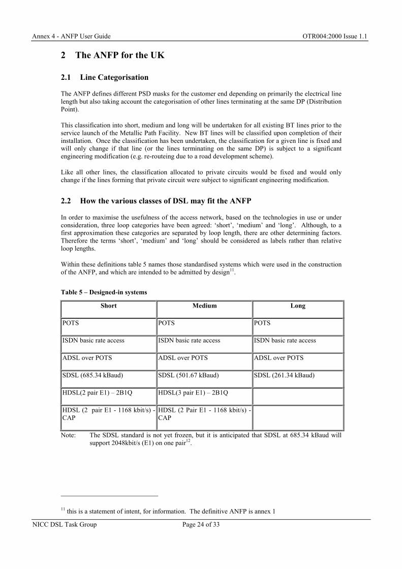
2.2 How the various classes of DSL may fit the ANFP
In order to maximise the usefulness of the access network, based on the technologies in use or underconsideration, three loop categories have been agreed: ‘short’, ‘medium’ and ‘long’. Although, to afirst approximation these categories are separated by loop length, there are other determining factors.Therefore the terms ‘short’, ‘medium’ and ‘long’ should be considered as labels rather than relativeloop lengths.
Within these definitions table 5 names those standardised systems which were used in the constructionof the ANFP, and which are intended to be admitted by design11.
Note: The SDSL standard is not yet frozen, but it is anticipated that SDSL at 685.34 kBaud willsupport 2048kbit/s (E1) on one pair12.
11 this is a statement of intent, for information. The definitive ANFP is annex 1
Annex 4 - ANFP User Guide OTR004:2000 Issue 1.1
NICC DSL Task Group Page 25 of 33
The ANFP does not exclude specific systems; it excludes by implication : one may not install a systemwhich does not conform to the masks at each of its ends. For example the issue 1.1 ANFP wouldexclude the following standardised systems13 from use on any BT access network line (‘short’,‘medium’ or ‘long’):
• A 1-pair 2Mbit/s HDSL system using 2B1Q or CAP
• ADSL over ISDN
• Reverse ADSL ( i.e. with the high bandwidth implemented in the customer to exchange direction).This means that ADSL is precluded from use on private circuits.
3 Ensuring equipment conforms to the ANFP
All equipment connected to the BT metallic access network needs to comply with the ANFP. Hencethis includes:
• BT equipment connected to the metallic access network
• network operator equipment connected to a Metallic Path Facility
• customer equipment connected to an analogue NTP that is either directly or indirectly connected tothe BT metallic access network, to the extent that its behaviour is relevant to conditions present onthe metallic access network itself.
The ANFP is currently enforced through the following measures.
3.1 Enforcement on Network Operators
The contract between BT and network operators for provision of Metallic Path Facility requires bothparties to comply with the ANFP. Demonstration of compliance is via a system of self-declaration.
Note 1: A Test Specification (Annex 2) has been defined to test telecommunications equipment forconformance to the ANFP. The contract between BT and network operators requiresnetwork operators to “..ensure that Compliant Equipment to be connected to the MetallicPath Facility is tested, using the Access Network Frequency Plan Test Specification forcompliance to the Access Network Frequency Plan” However it is up to the networkoperator whether it undertakes conformance testing itself or requires the supplier or a thirdparty to undertake it.
12 SDSL line rate is cited in kBaud because this is the aspect of line rate which concerns the ANFP. Auser may be more interested in nett data rate; there is also a gross data rate, which includes the modempair’s own overheads. In the current draft of the standard
gross data rate = nett + 8 kbit/sand line baud rate = gross data rate ÷ 3The rates used in the ANFP construction are
SDSL rates Gross data rate Symbol rate Nett data rate
Minimum, all masks 64 kbit/s 21.33 kBaud 56 kbit/s
Whatever way conformance is demonstrated, the responsibility for the declaration and the correctnessof that declaration resides with the network operator. In the event of a dispute on the conformance of apiece of telecommunications equipment, the Test Specification (Annex 2) will be used.
Note 2: as NTEs for analogue circuits are typically transparent to the signals generated by customerequipment, a customer's equipment that is non-complaint to the ANFP may cause undueinterference on the BT access network. It is the responsibility of the network operatorproviding service to that customer to resolve any interference issues caused by non-compliant customer equipment.
3.2 Enforcement on Customer Equipment
The essential requirements that customer equipment must meet before that equipment is allowed to beconnected to any public network is defined in the RTTE directive [6]. For customer equipment to beconnected to a public fixed network, the essential requirements are currently limited to safety andEMC.
The Revised Voice Telephony Directive (RVTD [5]) requires network operators14 to maintain theintegrity of their network. Further, RVTD Article 13(2b) requires network operators to declare theconditions under which access to the network will be restricted or removed in order to protect theintegrity of the network. Whilst the RVTD specifically applies to fixed public networks supportingvoice telephony, Article 3(2) of the revised ONP framework directive [3] makes the same requirementsapplicable to non-voice telephony networks.
Hence network operators employing MPFs should declare that conformance to the ANFP bycustomer's equipment is a requirement for network integrity and that access to the network may berestricted if ANFP conformance is not maintained. Such a declaration should be made in the networkoperator's interface specifications for the relevant services. Publication of these interface specificationsis a requirement under Article 4(2) of the RTTE Directive.
3.3 Enforcement on Equipment installed prior to the publication of the ANFP
As indicated in section 3, the ANFP has been developed taking account of existing equipment that hasbeen deployed in significant volume. There may exist equipment deployed in relatively low volumesthat does not comply with the ANFP e.g. existing CPE equipment approved for connection to analoguebaseband circuits (q.v. OFTEL ANFP Determination [12]). It is intended that the ANFP should not beretrospectively applied to such equipment and such equipment will be allowed to continue workingprovided it does not cause undue interference to other systems. If one of these pre-ANFP systems isfound to cause excessive interference, the resolution of the interference problem will be handled on acase-by-case basis.
If in the future the ANFP is amended, resulting in equipment that would have been compliant under thesuperseded edition of the ANFP not being compliant with the amended version of the ANFP, then thehandling of such equipment needs to be taken into account as part of the considerations concerning theamendment of the ANFP.
14 this means all network operators, not just the network owner
Annex 4 - ANFP User Guide OTR004:2000 Issue 1.1
NICC DSL Task Group Page 27 of 33
4 Policing the ANFP
4.1 Why are policing measures needed?
It should be stressed that if the interference preventive measures (e.g. ANFP conformance verificationprior to implementation as outlined in section 3) are universally applied, then there should be relativelyfew instances of interference problems. However some are still anticipated, for example those due to:
• equipment faults resulting in abnormally high power to line
• nonconformant equipment, as discussed in section 3.3
• unusually high crosstalk coupling from normal causes. The ANFP is based on a statistical modelof the network and access transmission systems with a 99% probability that conforming systemswill not cause interference.
Considering this last point, it is possible that interference could be experienced even where all systemson an access cable conform to the ANFP. Furthermore, as more xDSL systems are deployed the noiselevel in an access cable will increase with a possible consequential impact on the performance of thosesystems already deployed.
4.2 What is covered by the policing measures?
Interference may be either: -
• Between pairs within the access network cablesThis may not only be caused by other xDSL systems but could also be via ingress of radiointerference or from other non-xDSL customer CPE connected to other pairs in the cable.
• From or to systems external to the cable.
The ANFP covers only the interference between pairs within a cable and hence the ANFP policingmeasures only cover such situations. EMC regulations and measures within the Wireless TelegraphyAct cover interference from or to systems outside the cable.
4.3 What type of policing measures is to be adopted?
The development of pro-active measures or detailed procedures and specifications, which would beused very infrequently, is seen to be potentially expensive and unnecessary. Particularly in the earlydeployment where it is expected that there will be low numbers of systems in particular cables in mostcases.
It has therefore been decided that the “Policing System” should be consumer complaint drivensupported by a Code of Practice. The results of managing the interference complaints will providefeedback on the Code of Practice and hence this is likely to be changed as a result of experience.
4.4 Outline of Code of Practice
The policy has been adopted to try to eliminate all outside causes of a reported problem beforeexpensive investigation of the multiple systems within a cable is undertaken. That may of necessityinvolve a number of operators within an MDF site and could cause the interruption of service to apotentially large group of their customers.
Annex 4 - ANFP User Guide OTR004:2000 Issue 1.1
NICC DSL Task Group Page 28 of 33
More detail of these measures is given in the Code of Practice but this would involve for example: -
• Questioning the customer concerning what other equipment is connected to their line.
• Checking that the reduction in service reported by the customer is a valid complaint by :-
Reviewing against the deployment rules to check that they have been followed.
Checking that the performance achieved does fall short of that in the service level agreement.It is possible that higher rates than those guaranteed by the ANFP could be achieved when thecable was lightly loaded with xDSL traffic but that this reduces as more users are added.
• Changing the DSLAM and Customer modems
• Possibly checking the MFP for any significant change from its initial measured parameters
4.5 The need for co-operation
It has been recognised that policing the ANFP and finding problems will only work if there is co-operation and trust between the operators involved. This will also require the rapid exchange ofinformation concerning the technical details of the services being passed on pairs within an affectedcable where the initial investigations, outlined above, fail to find the source of the problem.
Specifically co-operation will be required to investigate periodic interference or events that occur atspecific times.
5 Evolution of the ANFP
Any changes to the ANFP can adversely affect (e.g. in terms of reduced reach, reduced performance)the transmission systems permitted in the original plan. Such changes would impact on the businesscases not only of the network operator(s) using those adversely affected systems but also of the users(e.g. ISPs, Customers) using those systems. Hence the mechanism for the control of changes to theANFP needs to be pre-defined so that users can assess the risks associated with possible changes.
The agreed change control procedure for the ANFP can be found in Annex 6.
Annex 5 - ANFP History & Background OTR004:2000 Issue 1.1
3.2 The agreed approach to an ANFP for the UK ....................................................30
1 Introduction
At the request of OFTEL, the Network Interoperability Consultative Committee (NICC) DSL TaskGroup was reconvened to address various technical aspects of local loop unbundling (LLU). Thisincluded the development of an Access Network Frequency Plan (ANFP) to control interference withinthe access network. The group started work in September 1999 and this issue of the ANFP coversphase 1 (up to 1.1 MHz). Work on stage 2 is now in progress and will cover additions for VDSL basedsystems
2 The need for an Access Network Frequency Plan
In order to maximise the capability of the systems deployed over the copper network the effects of theirmutual interference must be minimised. Even in the case of a single operator network an overall cablemanagement plan must be in place to achieve this objective. However where there are multipleoperators over the same infrastructure, as in the case of an unbundled local loop access network such aplan is essential in order that:-
• Maximum benefits in terms of bandwidth and quality of service are obtained for the end user
• All operators can understand the limitations the network places on their service delivery capability.
• Installation is simplified by increasing the certainty of being able to deliver the required service
• Disputes may be minimised
• Disputes may be settled in a transparent way
3 The ANFP for the UK
The ANFP, Issue 1 as specified in the main part of this document was developed as a result of theproposals defined in the OFTEL Access to Bandwidth statement (November 1999). The constructionof the ANFP was based on the criteria:-
• set out in the OFTEL Access to Bandwidth statement (these are reproduced in section 3.1)
• defined by the DSL Task Group (see section 3.2).
• defined in the OFTEL determination on the ANFP [12]
Annex 5 - ANFP History & Background OTR004:2000 Issue 1.1
NICC DSL Task Group Page 30 of 33
In deciding the criteria to be used and the method of construction for the ANFP, the DSL Task Grouptook account of the work on this subject being undertaken in ANSI T1.E1 and ETSI TM6.
A non-exhaustive list of generic xDSL systems that are permitted by the ANFP (Issue 1.1) is given intable 5 (part of Annex 4, the ANFP User Guide). This list is not definitive and is provided for guidanceonly.
3.1 OFTEL Statement
Extract from OFTEL’s Access to Bandwidth Statement [8], concerning the requirements for the ANFP:
OFTEL’s Spectral Management Plan Objectives
B31 OFTEL’s high level objectives for the spectral management plan (SMP) are:
• High customer penetration
• Technology neutral
• Minimal management processes
B32 It is OFTEL’s goal to ensure the availability of broadband access to the largestproportion of the UK population as possibly. Ideally this would be 100%, however asdiscussed in paragraph B23 this is unlikely to be achievable using only BT’s copperaccess network, instead a trade-off between the quality of the PBLCs15 and thepotential penetration level is required. Based on consultations with various technicalgroups OFTEL considers that a customer penetration level of 80 - 85% should be usedas the design objective for the SMP.
B33 To ensure that the SMP is flexible, non-restrictive and contains a degree of futureproofing OFTEL believes that it should be defined in a technology neutral fashion. Forthis reason OFTEL would favour the use of power spectral density (PSD) masks todescribe the signals that can be connected to the network at different locations. It isrecognised that at the present time ADSL and HDSL are likely to be the maintechnologies deployed, indeed HDSL in two and three pair form is already widelydeployed in the network. It is therefore considered that the PSD masks should allowfor the deployment of these technologies.
B34 In order to minimise the management costs associated with option 2 and to ensure itstimely introduction, OFTEL believes that the SMP should be produced in such a way asto avoid the need for complicated and restrictive management processes. To this endmix quotas for certain services within a binder group and binder group configurationcontrol should be kept to a minimum and if possible avoided altogether.
3.2 The agreed approach to an ANFP for the UK
The following principles were agreed by the UK industry technical body as the basis for themanagement of DSL system deployment within a cable. The numbering does not represent any formof priority or hierarchy.
15 PBLC – Partial Baseband Leased Circuit. This term was subsequently changed to Metallic PathFacility in the BT Licence Conditions
Annex 5 - ANFP History & Background OTR004:2000 Issue 1.1
NICC DSL Task Group Page 31 of 33
1. No pair segregation management within the access cableOne approach to the problem of management of DSL system deployment, adopted by somecountries, is to specify the numbers and types of system that may be deployed in a particularcable. Because crosstalk interference is principally only a major issue between adjacent pairs –(normally about 6/7 pairs) it could be possible to control these effects by careful allocation of thesystems used on adjacent pairs. This possibility has been rejected for the UK because:-
Historically, a “random jointing” policy was adopted in the BT copper network. A typical cable is pulled into a duct in sections, and the sections later jointed. Randomjointing means the relative positions of pairs are not maintained between sections. Henceadjacent pairs in one part of the cable may not be adjacent in another part of the cable. Pairsegregation is not possible in the BT access network.
The implementation of such a management function would require an associated process tobe developed which would be very complex, costly, time consuming and require nominatedresources. Such a process would also have to take account of additions and alterations toboth the transmission systems used on the cable and the cable itself.
2. Any transmission system on any pairThe adoption of an Access Network Frequency Plan would allow any transmission system thatconforms to the plan to be used on any pair in the access cable. This means that the ANFP wouldallow :-
any pair in an access cable to support any of the transmission systems allowed by the ANFP.
all pairs in the cable to support the same transmission system (i.e. 100% fill).
3. ANFP will be under pre-defined change controlAny changes to an ANFP can adversely affect (e.g. in terms of reduced reach, reducedperformance) the transmission systems permitted in the original ANFP. Such changes wouldimpact on the business cases not only of the network operator(s) using those adversely affectedsystems but also of the users (e.g. ISPs, Customers) using those systems. Hence possible changesto the ANFP need to be taken into account in the risk assessment of any business case using theaccess network and such risks need to be quantifiable if the evolution of the access network is notto be stifled. Hence the mechanism for the control of changes to the ANFP needs to be pre-defined so that users of the ANFP can assess the risks associated with possible changes.A defined change control process is not a prerequisite for Issue 1 of the ANFP.
4. Existing transmission systems in the BT access network should be included in Issue 1Development of the ANFP for the BT Access Network in the unbundled local loop environmentis not a ‘green field’ site. If existing customers are not to be adversely affected, it must takeaccount of transmission systems that have already been implemented in significant quantities.That is not to say that there can’t be changes in the future but these changes need to take place ina pre-defined manner governed by Principle 3 above.
5. Technology IndependentIdeally the ANFP would be technology independent. Whilst this can be an objective, it isprobably wishful thinking that the ANFP can be completely technology independent.
6. Protection of working systemsThe principal objective of the plan is to limit the behaviour of a system to protect its neighbours.This is the reason for a plan aimed at limiting spectra, since that’s all a victim system willperceive. So the technical objective is indifferent to the technology from which the noise came(modulation scheme etc just don’t matter).The objective of this principle is to ensure that a system permitted within the ANFP can operatewith a predictable minimum level of performance and quality of service.
7. SafetyThe ANFP must also protect human safety and the physical integrity of the wires. Such issues aregenerally covered by existing international standards and these standards need only to bereferenced.
Annex 5 - ANFP History & Background OTR004:2000 Issue 1.1
NICC DSL Task Group Page 32 of 33
8. ADSL over POTS is the chosen ADSL systemThere are two variants of ADSL systems, ADSL designed to work over POTS and ADSLdesigned to work over ISDN. These are spectrally incompatible. The ANFP will allow thedeployment of ADSL over POTS at the expense of ADSL over ISDN. This means that ADSLover ISDN will not be allowed by the ANFP and customers with ISDN wanting to also haveADSL will need a second metallic pair.
9. ANFP Phased developmentTaking account of the complexity in developing and specifying an ANFP and the need to have anANFP published in the timetable required by the OFTEL Access to Bandwidth requirements, thedevelopment of the ANFP will be split into 2 phases. ANFP, Issue 1 will cover frequencies up to1.1 MHz (i.e. include ADSL but not VDSL) and the transmit power allowed above 1.1 MHz willbe set very low in order to protect that frequency spectrum for future allocation. Subsequentissues of the ANFP will specify frequencies up to 30 MHz (i.e. include VDSL).
Annex 6 - ANFP Change Control Procedure OTR004:2000 Issue 1.1
NICC DSL Task Group Page 33 of 33
Annex 6 – ANFP Change Control Procedure
The following ANFP Change Control Procedure is agreed and adopted by the NICC DSL TaskGroup16.
Recognising that:
a) the implementation of the ANFP limits the type of telecommunications system that can beconnected to the BT Access Network and the location of that connection.
b) the implementation of the ANFP limits the noise experienced by systems connected to the BTAccess Network.
c) the business plans of network operators, service providers and customers may be affected bychanges to the ANFP. Hence the stability of the ANFP (i.e. minimum period that could existbefore the ANFP could be changed to the detriment of an organisations or individuals plans) needsto be defined in order that commercial risks can be assessed and investment decisions taken.
d) experience with the operation of the BT Access Network in a multi-operator environment mayprovide improved understanding of the complex crosstalk interaction between telecommunicationsystems operating on different metallic pairs within the BT Access Network. This improvedunderstanding may result in the need to amend the ANFP.
the NICC DSL Task Group adopt the following change control procedure for the ANFP:
1. A proposal to amend the ANFP may be submitted at any time by any interested party. Theproposal shall be submitted to OFTEL. It is recommended that OFTEL request the DSL TaskGroup to provide advice on the acceptability of the proposed amendment.
2. Any proposal to amend the ANFP should contain: -
• an impact assessment statement on at least the telecommunication systems listed in table 5(part of Annex 4, the ANFP User Guide)
• a proposed date for implementation.
3. The NICC DSL Task Group will adopt a proposed ANFP amendment if there is consensusagreement i.e. there is no sustained objection from any member of the Task Group.
4. Any objection to a proposed amendment should be supported by technical data to support thereasons for the objection.
5. Where there is no consensus agreement, the proposed amendment shall be passed to OFTEL fordetermination.
6. Changes to this ANFP Change Control procedure shall be via consensus agreement in the NICCDSL Task Group. Failure to reach consensus agreement will result in the proposed ANFP ChangeControl amendment being passed to OFTEL for determination.
- End -
16 The NICC DSL Task Group is not a permanent body and the Task Group will close once all thedeliverables allocated to the group have been completed. The requirement to consider proposals tomodify the ANFP may exist after the closure of the DSL Task Group. In this case, it isrecommended that OFTEL ask an appropriate UK industry forum to consider the proposedamendment and that that UK industry forum adopts these change control procedures.