79
ALGORITHMIC SKETCHBOOK LI AI ANG 560558 A I R A I R
ALGORITHMIC SKETCHBOOKLI A I ANG5 6 0 5 5 8
A I RA I R
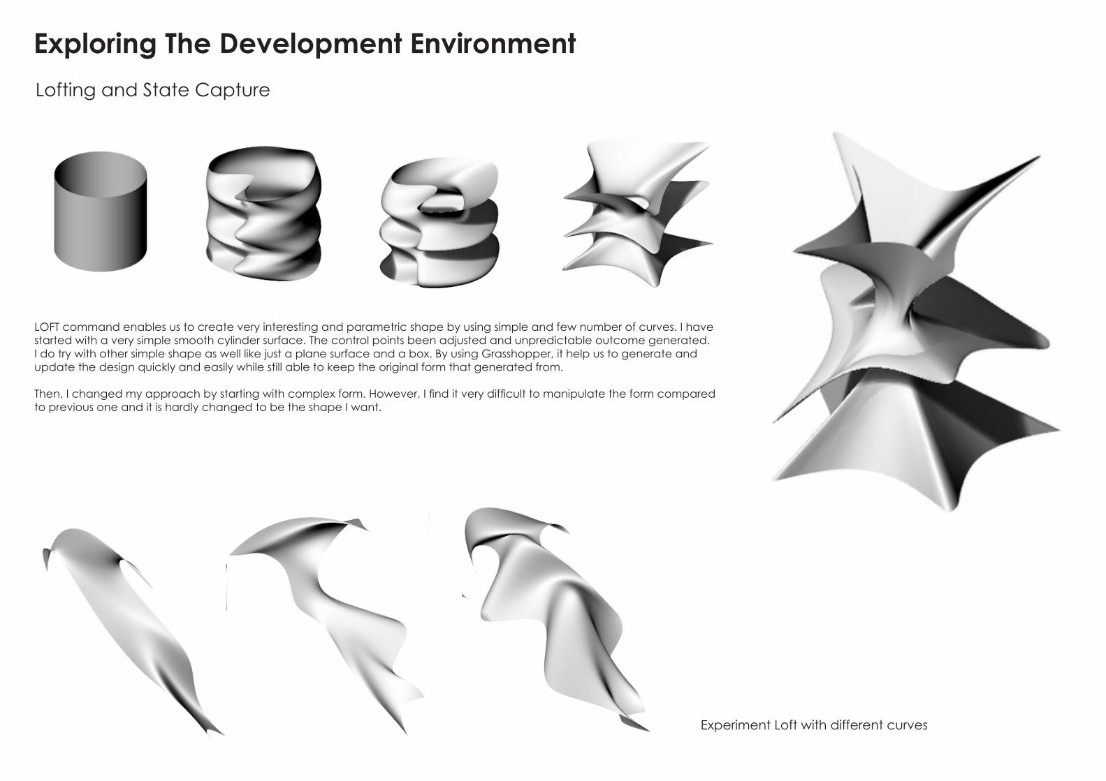
Lofting and State Capture
Exploring The Development Environment
Experiment Loft with different curves
LOFT command enables us to create very interesting and parametric shape by using simple and few number of curves. I have started with a very simple smooth cylinder surface. The control points been adjusted and unpredictable outcome generated. I do try with other simple shape as well like just a plane surface and a box. By using Grasshopper, it help us to generate and update the design quickly and easily while still able to keep the original form that generated from.
Then, I changed my approach by starting with complex form. However, I find it very difficult to manipulate the form compared to previous one and it is hardly changed to be the shape I want.

Triangulate Algorithms
Populate 3D --> Voronoi 3D
OcTree
In this demonstration video, populate 2D grid and popu-late 3D Grid have been introduced which connected to different triangulate mesh such as Voronoi and Octree.
By using populate 2D command in Grasshop-per, it enable to generate pattern on surface., while populate 3D command helps us to gener-ate structure or the proportion for the building design.
Exploration with different types of mesh

Understand Geometry, Transformations and Intersections
In this tutorial, I have exposed to how to generate mesh from a geometry form and how the result been soften to more dynamic form which generated from a angled rigid box. As mesh generated, we will be able to send the planar panels to factory to be cut. In this method, even the form been soften, the mesh surface changes follow the form. As can see from top right image, the parametric model could be manipulated into mesh surface and chenged to polyline.
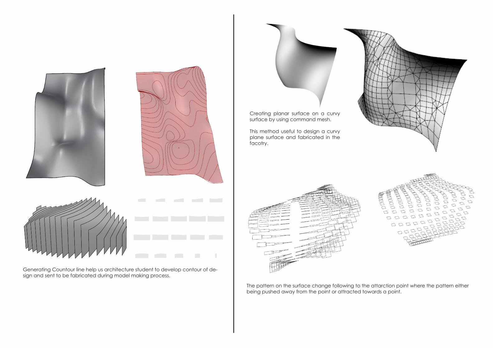
Creating planar surface on a curvy surface by using command mesh.
This method useful to design a curvy plane surface and fabricated in the facotry.
Generating Countour line help us architecture student to develop contour of de-sign and sent to be fabricated during model making process.
The pattern on the surface change following to the attarction point where the pattern either being pushed away from the point or attracted towards a point.

This method is very useful in generating 3D panel surface either the facade or the form itself. By inserting the command and linked together in Grasshopper, it is a very fast way to generate the panels and could be developed and experimented with different panels.
This method is ap-plied in the pavil-ion in University of Stutgart, Germany, where polygon 3D panel along the form and holes in between to allow sun light enter the pavilion.

Controlling the Algorithms
The Grid Shell system enable us to create parametric design models and how the struc-tural could be formed along the parameters.
Creating plane with number of point in both Y-axis and X-axis
After generating the plane with number of points, differ-ent command had been tested. One of the patterns that I found quite interesting is shown as above.By controlling the number of slider, with the same number of point and same number of circle, different patterns were generated.
This pattern generated is quite interest-ing as by controling the panels (true and false), the size of triangles shifted . As the result, the pattern seems to be a folded paper instead of plane surface.
This method is relatively useful to generate the surface of a skin facade or even the form of design. The most interesting part is by manipulating the slider number, different shape generated. As we changing the panels (adding true / false), some edges has been dissappeared and interesting pattern formed.

PART B Algor ithm Sketchbook

I n t r o d u c i n g P a r a m e t e r S p a c e , D a t a T y p e s a n d F u n c t i o n s
Field Fundamentals Expressionsthis method enabes us to manipulate the vector of the forces and the field charge by using poin attractors or curve attrac-tors. The arrows display the vector of the forces following the field either attracted towards the point attractors of repelled outwards from the point attractors.
Using Direction Display and Scalar Display illustrate visually the forces acting on the field section
The method explores on creating circle panels on unplanar surfaces by evaluating the surface and associated with math-ematics equation to generate different sizes of panels equally distributed on the surface.
The panels have to be on the surfaces as they could not stand by themselves. Useful in creating patterns pr panels on surface.

Fractal Tetrahedra
instead of creating the geometry in Grass-hopper, the brep was created in Rhino and been bring in Grasshopper.
More complex and complicated form generated compared to the previous method. The form seem to be out of con-trol.
The result was baked. Similar definition been used, however, very different re-sult generated, The outcome was kind of failed to generate the geometries.
Complex geometry formed by using simple single geometry. The geome-try been scaled in different scale and filled the body of the parent geom-etry. In this case, the panel itself can form the whole structure as the pan-els are able to interlocked with each others.
More and more complex geometry could be generated by increase the number of sides and also the number of scale on the geometry.

Evaluating Fields
I was amazed by this formed after its been generated. Similar to the method at the right, circular force field been applied on the design and thus the curves are moving following the force field.
Curves formed following the fields and the direction of the curve been directed and end up generating interesting field lines. Different from other approach, this method generate form by us-ing curves and lines instead of lofting to surfaces.


In this video tutorial, different scale of geometry been generated ac-coridng to the light exposure of the image. For the fist approach with only single image been used, sin-gle pattern extruded following the image generated which this usually been applied on the panel of the facade to make interesting form. The facade been complicated by adding one more layer of image un-derneath to generate two different pattern on the single facade.

C o n t r o l l i n g D a t a S t r u c t u r e s : V i s u a l i s a t i o n , P a t h O b j e c t s a n d M a t c h i n g
Points are represented by a set of numbers calledcoordinates
Points are one of the most basic geometricalelemente, use them to gener-ate more complex type
In our case,instead of generate the form by ourself, we use point to genee the form.
Param Viewer: tell us how the data being organ-ised-double click can have data tree structure( can see from single split into many structures)
Surfaces are defined generally as a set ofconnected points, reated in two dimensions typically done throughcurves

Tried with other data sets such as the shortest list and the longest list
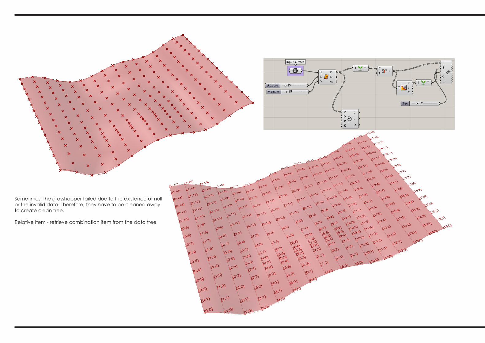
Sometimes, the grasshopper failed due to the existence of null or the invalid data. Therefore, they have to be cleaned away to create clean tree.
Relative Item - retrieve combination item from the data tree

Control l ing Data StructuresTree Statistics and Visualisation

Tree Dimensions

Tree Menu


Path Mapper
Path mapper - use indirect way much morecomplicated and complex compared to the pre-vious method. Instead of other mapper such as graph mapper, this method acquire knowledge on how should the connection been done by certain equation to generate certain form that we after.
I did find out that using Grass-hopper, a clear understanding behind the logic of the forma-tion such as the equation and the connection has to be under-stood to fully utilise the tools to easily generate the form that we actually looking for.

AA Driftwood Frames
This might be useful in my case design as in order to generate flexible, dynamic and responsive skin. slender Skeleton / structures is enough to support the skin layer. This method therefore enables me to generate the inner frame to hold the skin layer.
Undoubtedly, failure occured oftenly during the tutorial. Even following the example in the video tutorial, failure resulted.

Aranda Lasch - Continuous Patterning

Extending the Core Framework

Embedding Material Logic - Tensile and Rigid Bodies

IwamotoScott - Voussoir Cloud Input Geometry

IwamotoScott - Voussoir Cloud Form Finding

B.2. Case Study 1.0
As there are different approach in archieving the final result:
Initially,we are quite confused with how the definition works. The definition given has been divided into three different part and once the primary geometry formed, they were formed into mesh and connected to Kangaroo plug in. We have spend a long period in trying to combine the three different mesh and connected all of them into Kangaroo plug in. Howev-er, things does not work. Then we try to take a step back and restudy the definition.
After a while, we just realise we have move to a wrong direction. Different from other defini-tion, these definition is actually single, individual definition but just different ways to form the geometry. They are either curve formed geometry, exoskeleton to form geometry and using simple rigid geometry to form complex and dynamic geometry.
Basically, our group been divivded into four parts where three of us responsible for different approach and one person incharge of the Kangaroo plug in in order to generate the itera-tions.

After the comparison with other group members, I realized that the best way to generate the form is through the first approach which is using curves to generate the geometry. This approach enable to generate complex but yet specific form as we are been able to control and change the curves.
In this approach by using exoskeleton, simple lines were able to generate geometry by creating volume follow-ing the lines.
Able to change the number of sides of polygon generated, the radius, node size, knuckle bumpiness, and divi-sion of lenght along the tubes.
I was responsible in exploring using exoskeleton to form the geometry.

Iterations :

Failure Case:
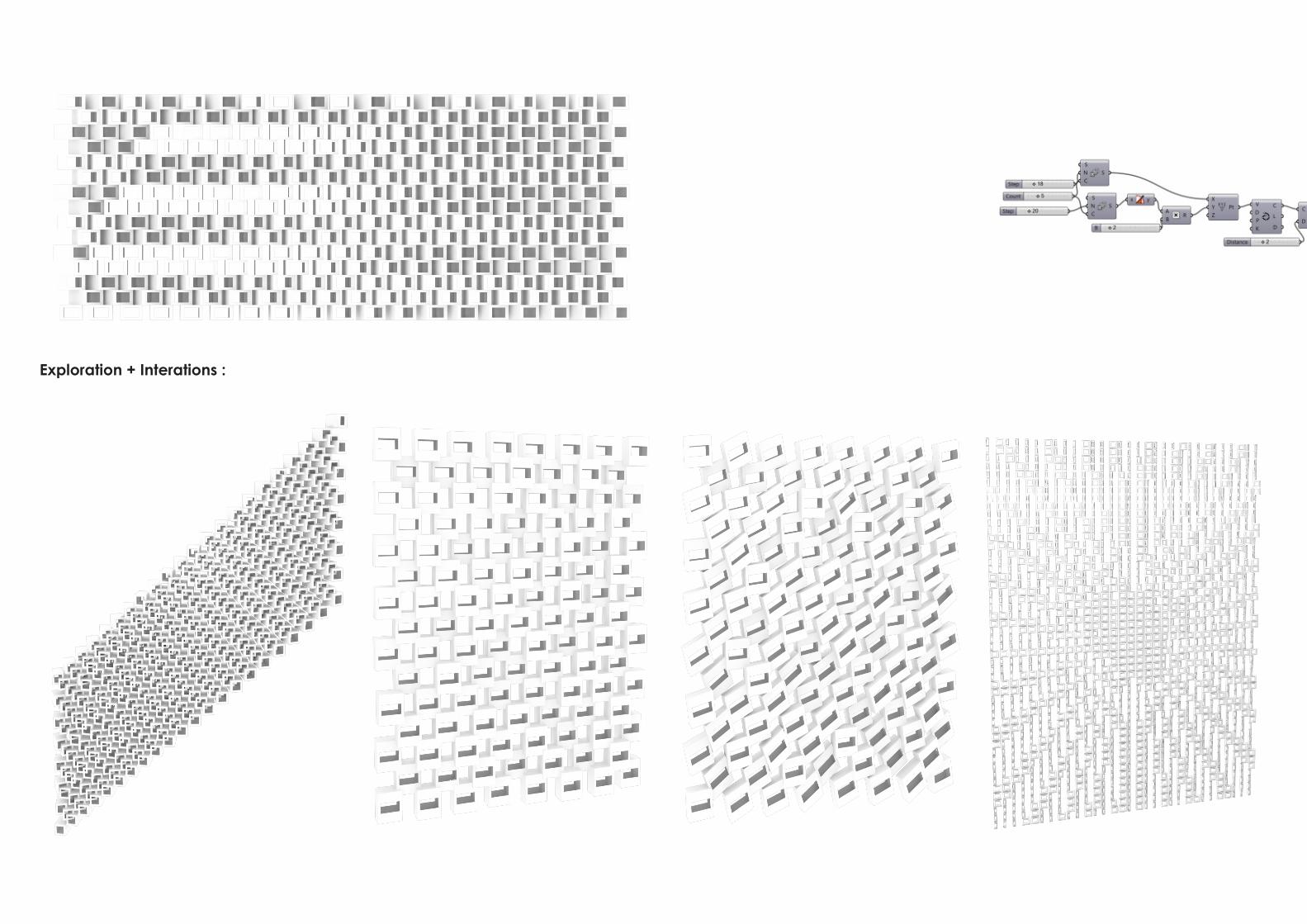
Exploration + Interations :

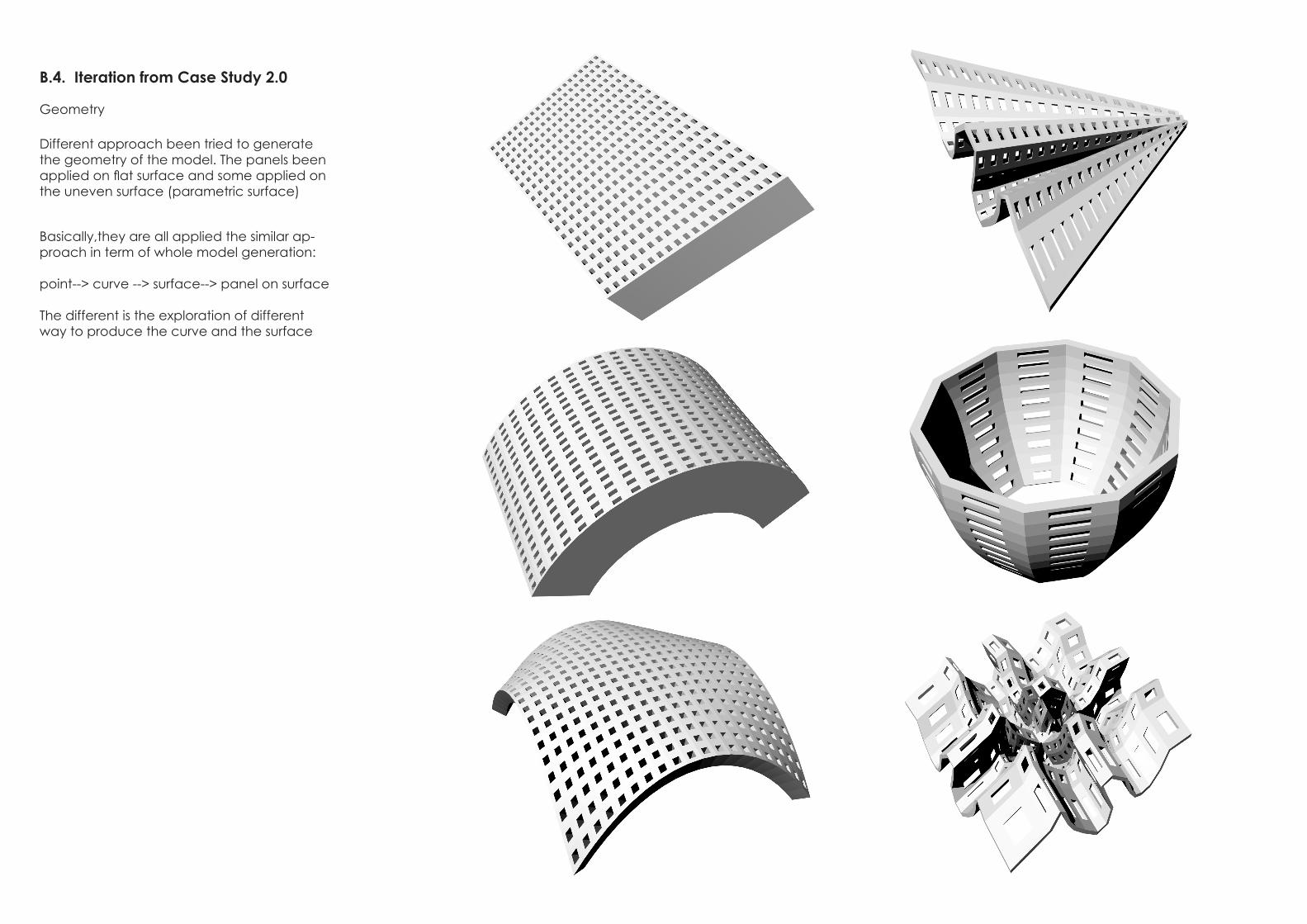
B.4. Iteration from Case Study 2.0
Geometry
Different approach been tried to generate the geometry of the model. The panels been applied on flat surface and some applied on the uneven surface (parametric surface)
Basically,they are all applied the similar ap-proach in term of whole model generation:
point--> curve --> surface--> panel on surface
The different is the exploration of different way to produce the curve and the surface
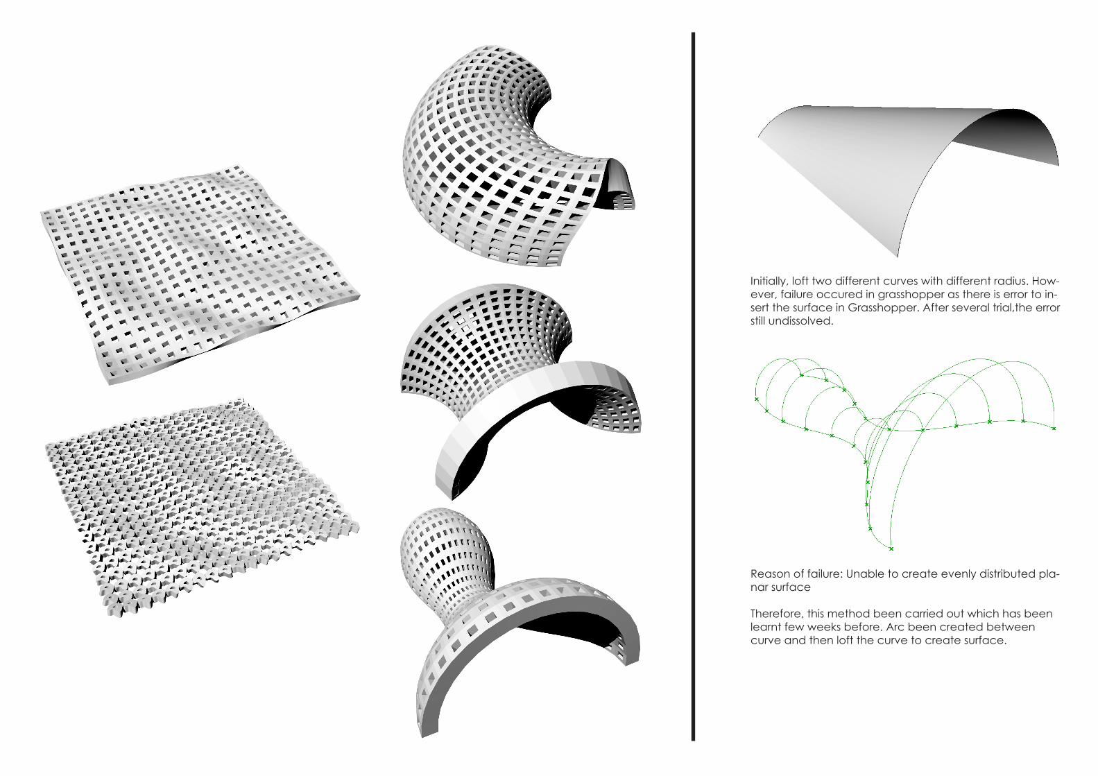
Initially, loft two different curves with different radius. How-ever, failure occured in grasshopper as there is error to in-sert the surface in Grasshopper. After several trial,the error still undissolved.
Reason of failure: Unable to create evenly distributed pla-nar surface
Therefore, this method been carried out which has been learnt few weeks before. Arc been created between curve and then loft the curve to create surface.

PART C Algor ithm Sketchbook

From the previous interim presentation, the feedback we got is that the form gener-ated from the wind data is too literal where is generate too -and hope to improve the form and be more focus in term of design intent/focus-and also lacking in relationship with the site context-and also hope to improve the spatial experience
As the result, we decide to start from site analysis like what we usually did in design studio.
Potential Circulation on the siteGreen: Circulation from the landRed: Circulation from the water taxi terminal
The level of exposure to the visitors which determine the most interesting facade of the design model.
Potential Site Function
Overlay all the site anlaysis and this is the form we get
S i t e A n a l y s i s
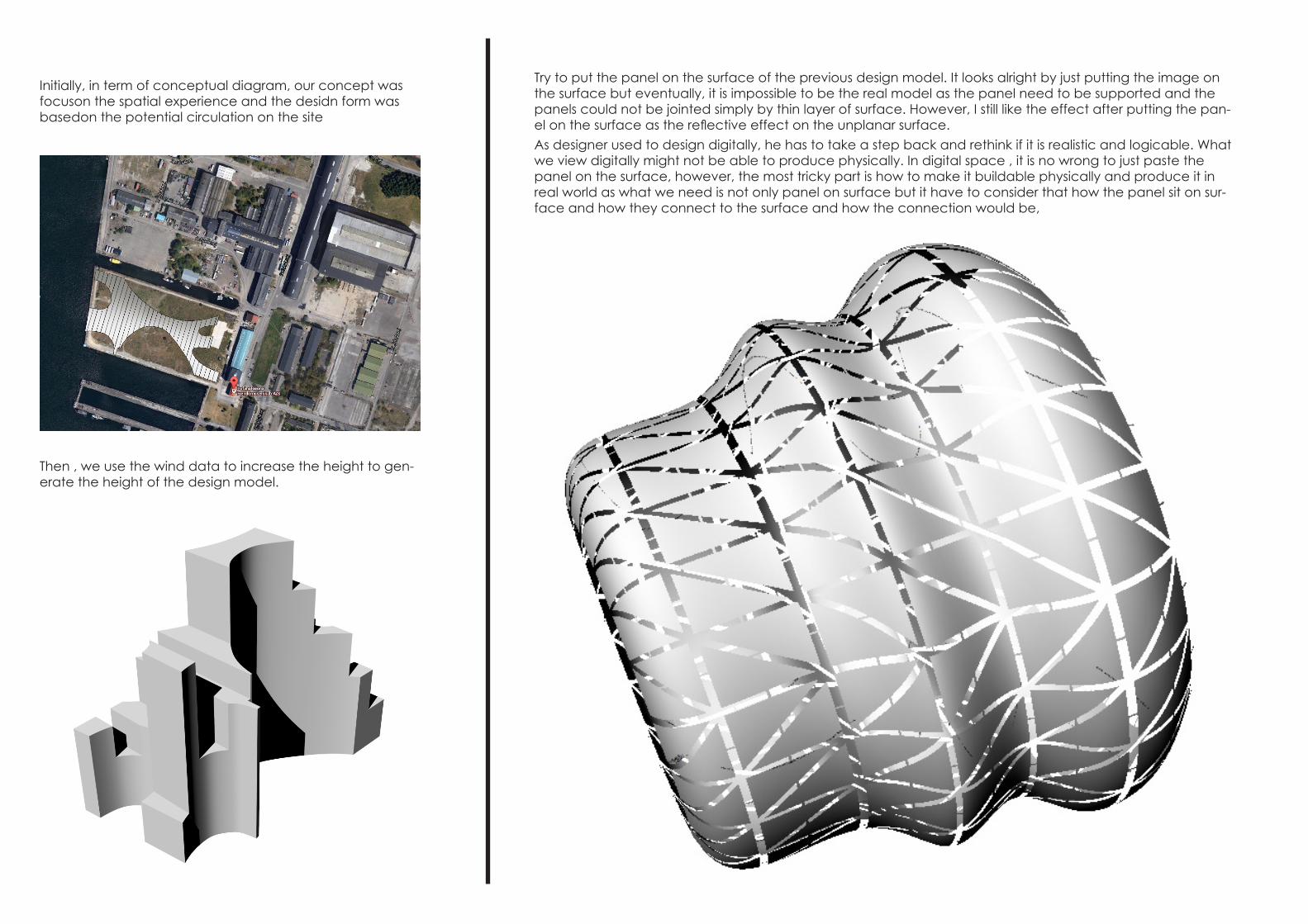
Initially, in term of conceptual diagram, our concept was focuson the spatial experience and the desidn form was basedon the potential circulation on the site
As designer used to design digitally, he has to take a step back and rethink if it is realistic and logicable. What we view digitally might not be able to produce physically. In digital space , it is no wrong to just paste the panel on the surface, however, the most tricky part is how to make it buildable physically and produce it in real world as what we need is not only panel on surface but it have to consider that how the panel sit on sur-face and how they connect to the surface and how the connection would be,
Then , we use the wind data to increase the height to gen-erate the height of the design model.
Try to put the panel on the surface of the previous design model. It looks alright by just putting the image on the surface but eventually, it is impossible to be the real model as the panel need to be supported and the panels could not be jointed simply by thin layer of surface. However, I still like the effect after putting the pan-el on the surface as the reflective effect on the unplanar surface.

The surface was rebuild and create large number of control points on the surface so that can be manipulate by pulling the points up and down and creating smooth surface. Interesting form generated by using this method. However, insetad of exploring grasshopper where the form been generated algorithmicly, thismethod is not efficient as been moved manually.

The form was raised in order to create more interesting spatial quality and also dynamic form. However, I am facing prob-lem with capping the top with closed surface. This is due to the unplanar surface created based on the different height of the curve and both side.
Then, I tried to create surface using”PATCH” command se-lecting all the curves on the top surfaces. Surfaces creat-ed successfully, however, the result is different from what I imagined with the smooth curve on the surface.
Even though, I still found the form generated is very rigid and not dy-namic at all. The reason probably because all the surface all did man-ulally without the use of parametric tools. Model is hardly manipulated on Rhino space. Then, Instead of surface, I move the curve to Grass-hopper and then rebuild surface individually. However, it is still unable to create surface on top.
At the end, I still go with patch command as at this time, I found out the result is quite success in create smooth flow of surface connected to all curves.

After the form been build, I tried to rebuild the form with different number of control point which is 10, 30 and 50 respectively. As the number of control point increase, instead of sharp edge, the edge of the curve became smoother than former. However, I still prefer the form of the first trial with least control points.

Put in the plasticine prototype and someother sketches.

I tried to make the physical model of the form by using plasticine. Rough shape been done and then been touch up and manipulat-ed in order to achieve the form that we looking after. I think modelling is one of the very useful method to test the form and to see how it works and the spatial quality within it. It enable me to foreseen the experi-ence and the architectural quality. The advantage of plasticine modelling is that it enable me to manipulate much easily by simply push the plasticine to make the form. However, compared to digital model, the ad-vantage is that the inner space is unable to be ob-served and only based on what I imagined and this is only the best methos to test the concept form but not the final form presentation.

Finish with the form, I start to analyse the structural system.
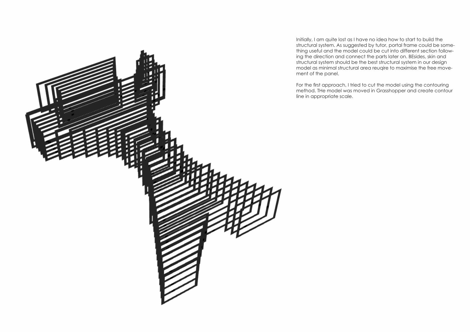
Initially, I am quite lost as I have no idea how to start to build the structural system. As suggested by tutor, portal frame could be some-thing useful and the model could be cut into different section follow-ing the direction and connect the parts later on. BEsides, skin and structural system should be the best structural system in our design model as minimal structural area reuqire to maximise the free move-ment of the panel.
For the first approach, I tried to cut the model using the contouring method. THe model was moved in Grasshopper and create contour line in appropriate scale.
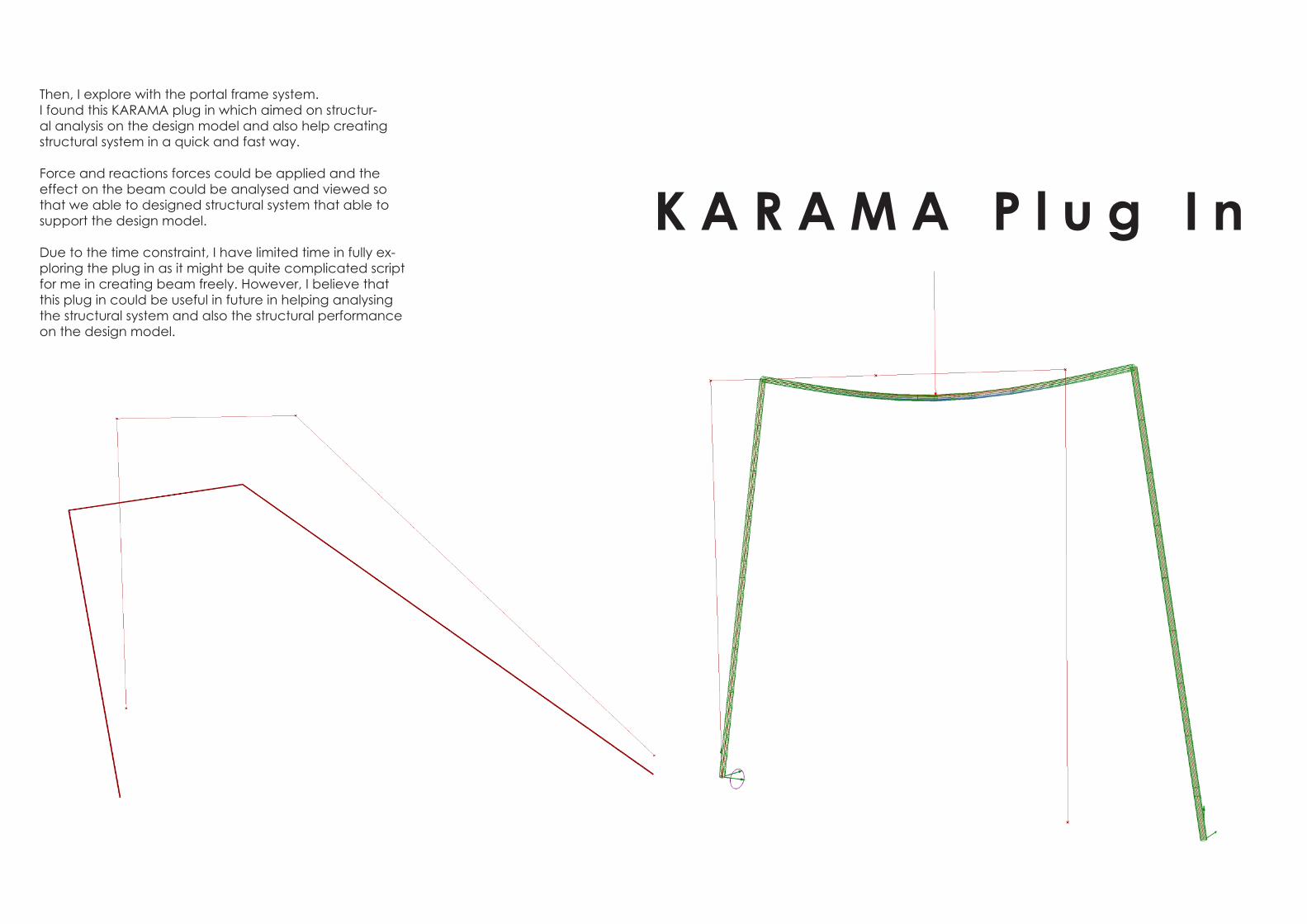
Then, I explore with the portal frame system.I found this KARAMA plug in which aimed on structur-al analysis on the design model and also help creating structural system in a quick and fast way.
Force and reactions forces could be applied and the effect on the beam could be analysed and viewed so that we able to designed structural system that able to support the design model.
Due to the time constraint, I have limited time in fully ex-ploring the plug in as it might be quite complicated script for me in creating beam freely. However, I believe that this plug in could be useful in future in helping analysing the structural system and also the structural performance on the design model.
K A R A M A P l u g I n


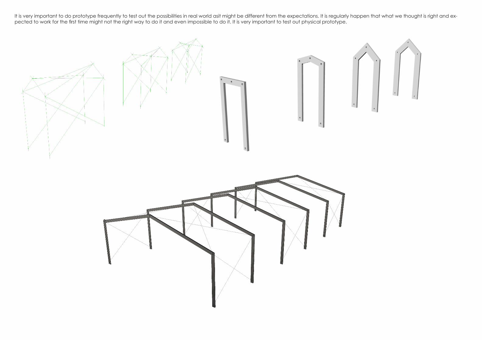
It is very important to do prototype frequently to test out the possibilities in real world asit might be different from the expectations. It is regularly happen that what we thought is right and ex-pected to work for the first time might not the right way to do it and even impossible to do it. It is very important to test out physical prototype.
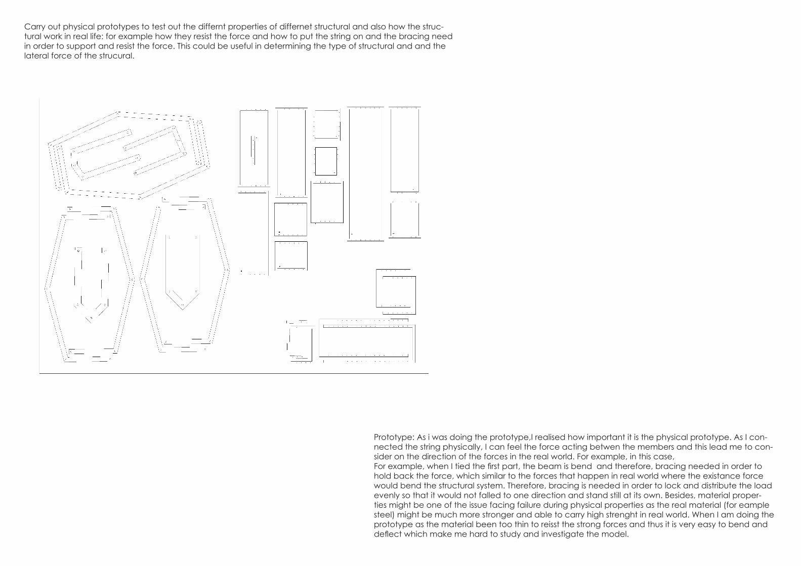
Prototype: As i was doing the prototype,I realised how important it is the physical prototype. As I con-nected the string physically, I can feel the force acting betwen the members and this lead me to con-sider on the direction of the forces in the real world. For example, in this case, For example, when I tied the first part, the beam is bend and therefore, bracing needed in order to hold back the force, which similar to the forces that happen in real world where the existance force would bend the structural system. Therefore, bracing is needed in order to lock and distribute the load evenly so that it would not falled to one direction and stand still at its own. Besides, material proper-ties might be one of the issue facing failure during physical properties as the real material (for eample steel) might be much more stronger and able to carry high strenght in real world. When I am doing the prototype as the material been too thin to reisst the strong forces and thus it is very easy to bend and deflect which make me hard to study and investigate the model.
Carry out physical prototypes to test out the differnt properties of differnet structural and also how the struc-tural work in real life: for example how they resist the force and how to put the string on and the bracing need in order to support and resist the force. This could be useful in determining the type of structural and and the lateral force of the strucural.
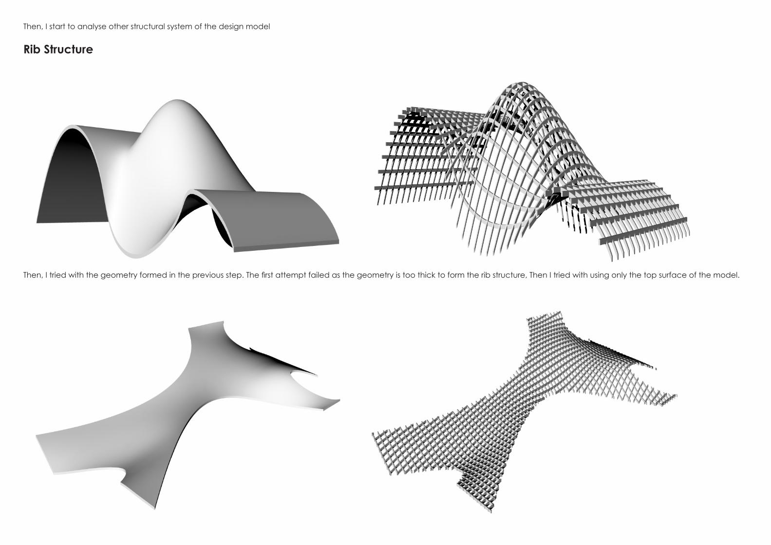
Then, I start to analyse other structural system of the design model
Rib Structure
Then, I tried with the geometry formed in the previous step. The first attempt failed as the geometry is too thick to form the rib structure, Then I tried with using only the top surface of the model.

Then, I applied in on the surface by creating it on individual surface and connecting everything as a whole.However, the result is not appealing and failed to achiece what I expected. The rib structure (with the cut off shape) would unable to sup-port the huge giant structure of the design model. It would bend and deflect very easily due to the thin surface and also less of support.
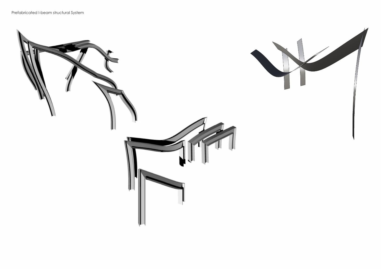
Prefabricated I-beam structural System

also realise the technique and skill needed while unrolling the model. Fir my first time, i just simply explode the model and rotate it facing planand just make2D and expected the result would be the same as the real model. However, when i assembly the model, i find out that the result is different from what i expected as teh sur-face is much shorter .This is because of not proper way to unroll and also the unplanar surface

Also test with different approach

The tunnel form with one way opening is quite simple compared to previous form.


Joint Fai led #1
In order to create fabric-like panel, how the panels connected is extremely important as it might affect the movement of the panel either further enhancing or restricting the movement.
the joint has be be fix to the panel individually as in this case, individual movement is not allowed in order to create a dynamic movement as a whole.


R e n d e r i n g
Different setting on rendering provided different feeling and experience and also provide audience different level of representation. Vray rendering was much better compared to default Rhino Rendering as it looks more realistic and smooth.

Not only the digital model and the design, how the digital model been represented played an important role as well in term of the quality, impression as well as understanding, All as-pects need to be considered carefully such as the angle, the light setting.
The most important image is the most evocative image which as mentioned in module A which enable to redirect people thinking -the most successful image that able to stimulate the viewers visual and mindset and also able to represent the design concept well
one of the most important technique in architecture is how to represent your own project and also stan out from others-the image should be abe to fully interpret the design concept and attract the client attrac-tion
failure in lighting setting where too drak and create drak interior
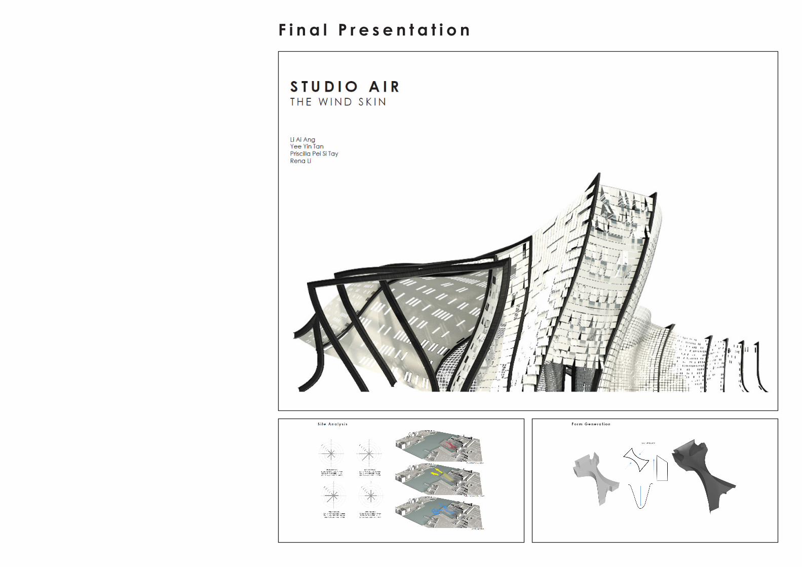
F i n a l P r e s e n t a t i o n


Exp lo r i ng New F o r m


F i n a l F o r m c h o o s e n

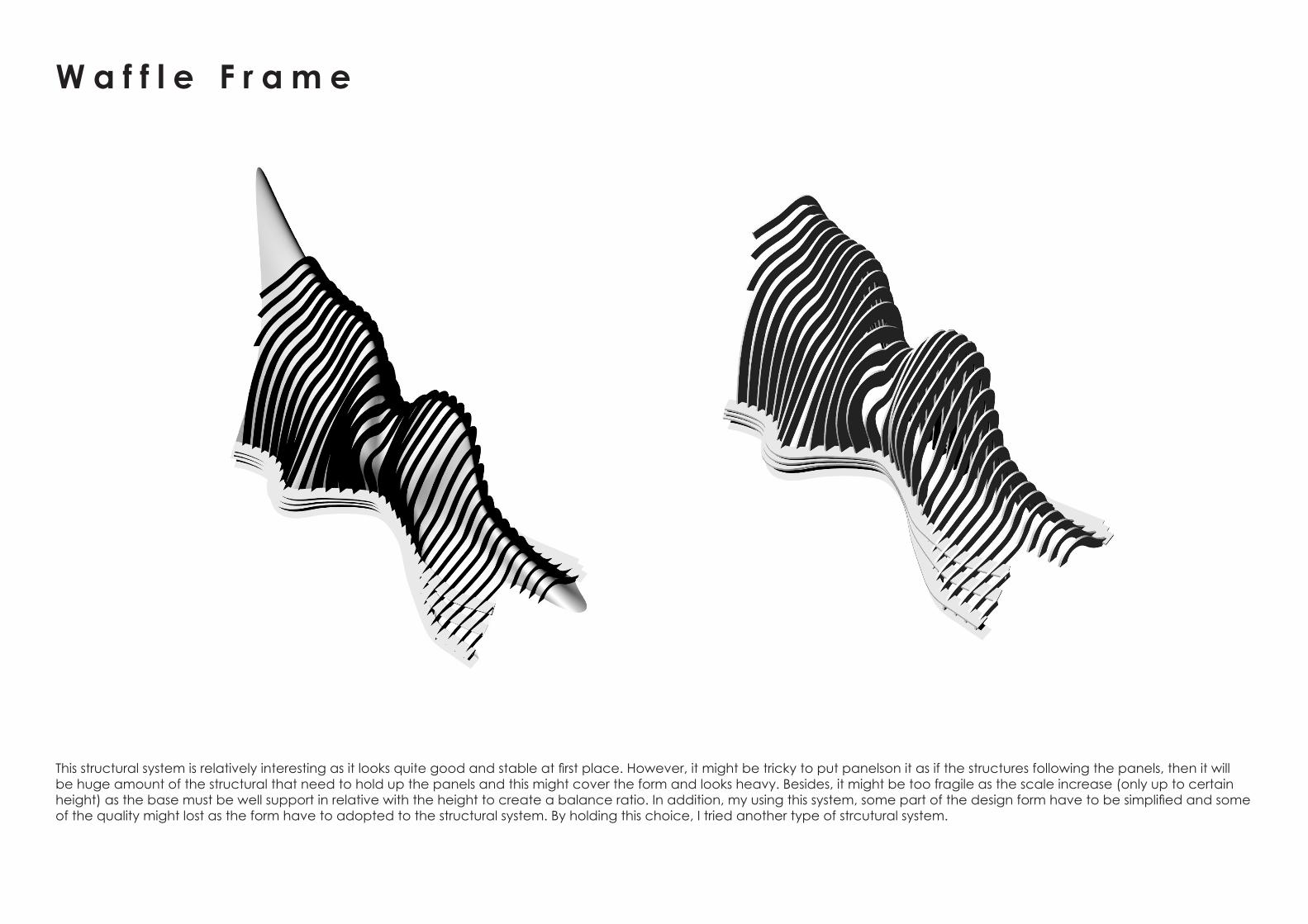
This structural system is relatively interesting as it looks quite good and stable at first place. However, it might be tricky to put panelson it as if the structures following the panels, then it will be huge amount of the structural that need to hold up the panels and this might cover the form and looks heavy. Besides, it might be too fragile as the scale increase (only up to certain height) as the base must be well support in relative with the height to create a balance ratio. In addition, my using this system, some part of the design form have to be simplified and some of the quality might lost as the form have to adopted to the structural system. By holding this choice, I tried another type of strcutural system.
W a f f l e F r a m e


F r a m i n g S y s t e m
This structural system looks more realistic,logical, an buildable compared to others, Bracing provided between element so that the form remain rigid and would not sway in opposite direction. The system alble to create support and also maintaining the dynamic form and the architectural quality that we looking for. However, due to the slender element, the whole structural looks relatively fragile. Then, I decided separate the system into primary structure with thicker radius and secondary structures so that the support system could be much better.


F r a m i n g S y s t e m : P r i m a r y a n d S e c o n d a r y S t r u c t u r e s
For this time, the structural system looks more supportive compared to the previous one. However, failure occured especially at the curvy part of the dynamic form. Besides, the barcing was in diamond form which would be quite tricky to place the panels on it. Therefore,this structural system is further developed in order to create better result.

For this time, the system was created by dividing the from into uniform and appropriate length. Grid form generated and the curves were later been bake into Rhino Spaces. ApplyCurvePiping command were used in generating the piping mesh following the curve. It was much better compared to the previous structural. As suggested by tutor, the window frame like structure concpet was applied in the design model so that the panel would fit into the structures nice-ly like how the window been fit into the window opening.

Panel Explorat ion


F i n a l P a n e l c h o s e n


