8
Angle-stable Foot plate system Pedus-L www.marquardt-medizintechnik.de
Angle-stable
Foot plate system
Pedus-L
www.marquardt-medizintechnik.de

Angle-stable Pedus-L foot plate system
Page 1
1. Product characteristics 01
· Hallux valgus with persistent symptoms- Pseudoexostosis- First metatarsophalangeal joint
Intermetatarsal angle > 16°-20°
Unstable 1st tarsometatarsal joint
Arthrosis in the1st tarsometatarsal joint
Re-intervention
Misalignment of the 1st tarsometatarsal joint
·
·
·
·
·
3. Indications for Lapidus arthrodesis
> Angle-stable Pedus-L foot plate system
· The centre hole offers the option of inserting a corticalscrew to exert compression on the arthrodesis site
The combination holes offer the option of using angle-stable and non angle-stable screws
Titanium screws and plates
Special surface treatment involving type II anodisation ofplates and angle-stable screws
This results in:- reduced tendency to cold welding when screws are
turned into the plate- hardened titanium surface- implants have improved fatigue resistance- significant reduction inAl and V release
Simple instrument set with an easy overview
·
·
·
·
·
Dimensions of the Pedus-L implants
·
·
·
Proximal osteotomy with large cancellous contact areas
Good range of correction options
Good range of options for combining with otherinterventions
2. Advantages of Lapidus arthrodesis
Angle-stable cortical screws, 3.0 mm dia., Self-tapping
Cortical screws, 2.7 mm dia., self-tapping
Cannulated screws, 3.5 mm dia., partial thread, titanium
Pedus-L plates
Thread diameter: 3.00 mm
Core diameter: 1.95 mm
Pitch: 1.25 mm
Inner hexagon: 2.50 mm
Screw length: 16 mm to 30 mm
Material: Ti6Al4V; Eli (ISO 5832-3)
Thread diameter: 2.70 mm
Core diameter: 1.90 mm
Pitch: 1.00 mm
Inner hexagon: 2.50 mm
Screw length: 12 mm to 30 mm
Material: Ti6Al4V; Eli (ISO 5832-3)
Thread diameter: 3.50 mm
Core diameter: 2.50 mm
Pitch: 1.25 mm
Inner hexagon: 2.50 mm
Screw length: 34 mm to 42 mm
Cannulation: 1.35 mm
Material: Ti6Al4V; Eli (ISO 5832-3)
Step: 0/2/3/4/5 mm
Plate thickness: 1.6 mm
Material: Ti6Al4V; Eli (ISO 5832-3)
·
·
·
·
·
·
·
·
·
·
·
·
·
·
·
·
·
·
·
·
·
·
· Disorders of wound healing
Secondary dislocation
Pseudarthrosis
Nerve injuries
Transfer metatarsalgia
Over-correction
Rate of recurrence less than 10%
·
·
·
·
·
·
4. Complications

Page 2
Angle-stable Pedus-L foot plate system
2. Resection
After dissecting the soft tissues from the firstmetatarsophalangeal joint, a second incision is made onthe back of the foot over the 1st tarsometatarsal joint.(TMT1). (Fig. 1)
1. Access
After checking correct identification of the tarsometatarsaljoint (e.g. using a cannula and an image intensifier), aconservative resection of the articular surface is carried out.
The first tarsometatarsal joint always runs moreplantar than expected.
The resected wedge determines the direction of correction.It is usually easiest to align the arthrodesis surface at 90° tothe MT1 axis. A small osteotomy spreader facilitatesexposure of the full depth of the arthrodesis surface. Notethat the plantar side of the resected bone may be adhered tothe insertion of peroneus longus, making removal moredifficult.
Note:
> Surgical technique Lapidus arthrodesis
01
02
Page 3
Angle-stable Pedus-L foot plate system
> Implanting the plate
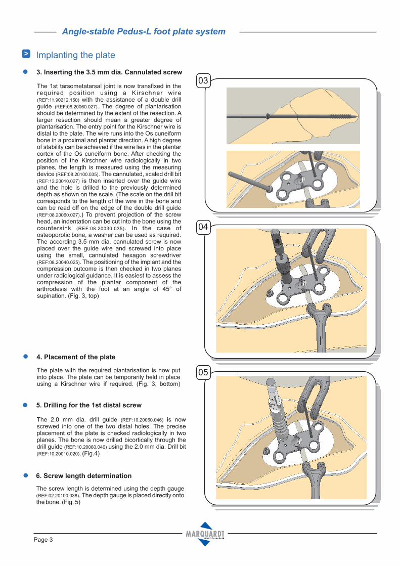
5. Drilling for the 1st distal screw
The 1st tarsometatarsal joint is now transfixed in therequired posi t ion using a Kirschner wire
with the assistance of a double drillguide . The degree of plantarisationshould be determined by the extent of the resection. Alarger resection should mean a greater degree ofplantarisation. The entry point for the Kirschner wire isdistal to the plate. The wire runs into the Os cuneiformbone in a proximal and plantar direction. A high degreeof stability can be achieved if the wire lies in the plantarcortex of the Os cuneiform bone. After checking theposition of the Kirschner wire radiologically in twoplanes, the length is measured using the measuringdevice . The cannulated, scaled drill bit
is then inserted over the guide wireand the hole is drilled to the previously determineddepth as shown on the scale. (The scale on the drill bitcorresponds to the length of the wire in the bone andcan be read off on the edge of the double drill guide
.) To prevent projection of the screwhead, an indentation can be cut into the bone using thecountersink . In the case ofosteoporotic bone, a washer can be used as required.The according 3.5 mm dia. cannulated screw is nowplaced over the guide wire and screwed into placeusing the small, cannulated hexagon screwdriver
. The positioning of the implant and thecompression outcome is then checked in two planesunder radiological guidance. It is easiest to assess thecompression of the plantar component of thearthrodesis with the foot at an angle of 45° ofsupination. (Fig. 3, top)
(REF:11.90212.150)
(REF:08.20060.027)
(REF:08.20100.035)
(REF:12.20010.027)
(REF:08.20060.027)
(REF:08.20030.035)
(REF:08.20040.025)
3. Inserting the 3.5 mm dia. Cannulated screw
The 2.0 mm dia. drill guide is nowscrewed into one of the two distal holes. The preciseplacement of the plate is checked radiologically in twoplanes. The bone is now drilled bicortically through thedrill guide using the 2.0 mm dia. Drill bit
. (Fig.4)
(REF:10.20060.046)
(REF:10.20060.046)
(REF:10.20010.020)
6. Screw length determination
The screw length is determined using the depth gauge. The depth gauge is placed directly onto
the bone. (Fig. 5)(REF:02.20100.038)
03
05
04
The plate with the required plantarisation is now putinto place. The plate can be temporarily held in placeusing a Kirschner wire if required. (Fig. 3, bottom)
4. Placement of the plate
Angle-stable Pedus-L foot plate system
Page 4
> Implanting the plate
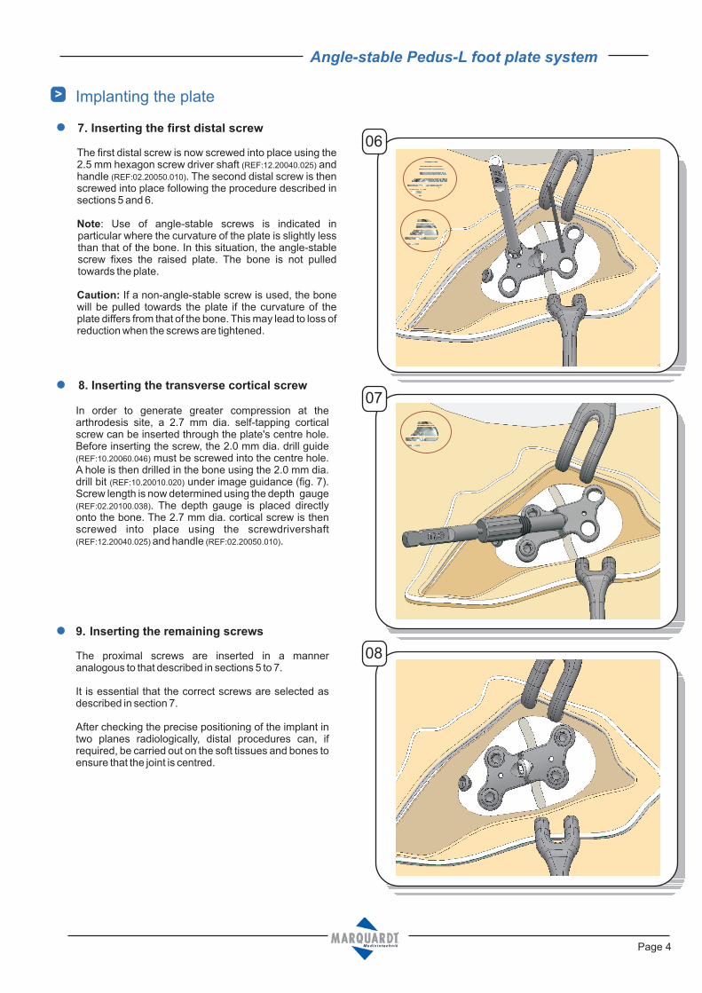
The proximal screws are inserted in a manneranalogous to that described in sections 5 to 7.
It is essential that the correct screws are selected asdescribed in section 7.
After checking the precise positioning of the implant intwo planes radiologically, distal procedures can, ifrequired, be carried out on the soft tissues and bones toensure that the joint is centred.
9. Inserting the remaining screws
In order to generate greater compression at thearthrodesis site, a 2.7 mm dia. self-tapping corticalscrew can be inserted through the plate's centre hole.Before inserting the screw, the 2.0 mm dia. drill guide
must be screwed into the centre hole.A hole is then drilled in the bone using the 2.0 mm dia.drill bit under image guidance (fig. 7).Screw length is now determined using the depth gauge
. The depth gauge is placed directlyonto the bone. The 2.7 mm dia. cortical screw is thenscrewed into place using the screwdrivershaft
and handle .
(REF:10.20060.046)
(REF:10.20010.020)
(REF:02.20100.038)
(REF:12.20040.025) (REF:02.20050.010)
8. Inserting the transverse cortical screw
The first distal screw is now screwed into place using the2.5 mm hexagon screw driver shaft andhandle . The second distal screw is thenscrewed into place following the procedure described insections 5 and 6.
: Use of angle-stable screws is indicated inparticular where the curvature of the plate is slightly lessthan that of the bone. In this situation, the angle-stablescrew fixes the raised plate. The bone is not pulledtowards the plate.
If a non-angle-stable screw is used, the bonewill be pulled towards the plate if the curvature of theplate differs from that of the bone. This may lead to loss ofreduction when the screws are tightened.
(REF:12.20040.025)
(REF:02.20050.010)
Note
Caution:
7. Inserting the first distal screw
06
08
07

Angle-stable Pedus-L foot plate system
Page 5
> Implanting the plate
After layered wound closure, a compression dressing isapplied with fixation.
6 - 8 weeks lower leg walker with 20 kg partial weight-bearing until ossification has taken place.
Increasing weight bearing following radiological follow-up.
Mobilisation of the first metatarsophalangeal joint,corrective bandaging and hallux splinting should beselected in accordance with the requirements of the distalintervention.
Post-operative care
·
·
·
10. Concluding the operation andpost-operative treatment 09
> Implants
Washer for cannulated screw Ø 3.5 mm, titanium Article no.
03.91000.070
Cannulated screw Ø 3.5 mm,partial threaded, titanium Article no.
08.03535.034
08.03535.036
Screw length
34 mm
36 mm
08.03535.038 38 mm
08.03535.040 40 mm
The angle-stable plate can alternatively be applied to the first tarsometatarsal joint medially or medioplantarly. In this caseextra attention must be paid to the tibialis anterior muscle, the insertion zone of which may in some cases stretch as far asthe distal Os cuneiform bone. Primary stability and compression at the arthrodesis site can also be improved with the useof an additional tension screw where alternative plate positions are used.
11. Alternative plate positions
08.03535.042 42 mm

Angle-stable Pedus-L foot plate system
Page 6
> Implants
Cortical screw Ø 2.7mm,self-tapping, titanium
Article no. Screw length
03.03527.012
03.03527.014
03.03527.016
12 mm
14 mm
16 mm
03.03527.018
03.03527.020
03.03527.022
03.03527.024
18 mm
20 mm
22 mm
24 mm
03.03527.026
03.03527.028
03.03527.030
26 mm
28 mm
30 mm
Angle-stable screw Ø 3.0mm,self-tapping, titanium
Article no.
10.03530.016
10.03530.018
Screw length
16 mm
18 mm
10.03530.020
10.03530.022
10.03530.024
10.03530.026
20 mm
22 mm
24 mm
26 mm
10.03530.028 28 mm
10.03530.030 30 mm
Pedus-L Plate, titanium Article no. Step
12.11123.000
12.11123.002
12.11123.003
12.11123.004
12.11123.005
0 mm
2 mm
3 mm
4 mm
5 mm

Dieter Marquardt Medizintechnik GmbH
-Robert-Bosch-Str.1 78549 SpaichingenTel: +49 (0) 7424 / 95810 - Fax: +49 (0) 7424 / 501441
INSTRUMETS IN THE SET
Angle-stable foot plate systemPedus-L
Ausgabedatum: 24.03.09
Description
Graphic case with implant rack 12.22130.012
Article no.
Implant rack
12.22130.150
12.22130.012
Rack for cannulated screw instruments 12.22130.160
12.22130.15012.22130.152
12.22130.012
Lid for implant rack 12.22130.003
Description Article no.
Screw holding forceps 02.20120.015
Handle
Double drill guide Ø1.7mm / Ø2.0 mm
Depth gauge
Kirschner wire Ø1.2x70 mm; trocar / round
02.20050.010
12.20060.017
02.20100.038
11.90012.070
Screw driver shaft 2.5 mm hexagon 12.20040.025
Drill bit Ø2.0 mm 10.20010.020
Drill guide Ø2.0 mm 10.20060.046
Kirschner wire Ø1.2x150 mm, trocar / round
Cleaning wire Ø1.2x230 mm
Screw holding sleeve
Double drill guide 2.7 mm / 1.25 mm
Drill bit Ø2,7mm, 160mm, cannulated, scaled
Countersink for Ø3.5mm cannulated screws
Screwdriver 2.5mm hexagon, cannulated
Measuring device for Ø3.5/4.0mm cannulated screws
11.90212.150
08.20120.135
03.20040.026
08.20060.027
12.20010.027
08.20030.035
08.20040.025
08.20100.035
Instruments for cannulated screw
10.2
0010.0
20
12.2
0040.0
25
10.2
0060.0
46
12.2
0060.0
17
02.2
0050.0
10
02.2
0100.0
38
02.2
0120.0
15
11.9
0012.0
70 / 1
1.9
0212.1
50
08.2
0040.0
25
03.2
0040.0
26
08.2
0060.0
27
12.2
0010.0
27
08.2
0030.0
35
08.2
0100.0
35
08.2
0120.1
35


