68
A PROJECT WITH PARTICULAR APPEAL TO THE NEWCOMER Also inside ANNEMININ zoe e so _s 01 - es <0 e e 09 0 ot e

A PROJECT WITH PARTICULAR APPEAL TO THE NEWCOMER
Also inside ANNEMININ
zoe
e so _s 01 -
es <0 e e 09 0 ot
e

QTV. DIODES/ZENERS
1N914 100v 10mA .05 1N4005 600v 1A .08 1N4007 1000v lA .15 1N4148 75v 10mA .05 1N4733 5.1v 1 W Zener .25 1N753A 6.2v 500 mW Zener .25 1N758A 10v .25 1N759A 12v .25 1N5243 13v .25 1N5244B 14v .25 1N5245B 15v .25
QTY. SOCKETS/BRIDGES
8 -pin pcb .20 ww .35 14 -pin pcb .20 ww .40 16 -pin pcb .20 ww .40 18 -pin pcb .25 ww .95 20 -pin pcb .35 ww .95 22 -pin pcb .35 ww .95 24 -pin pcb .35 ww .95 28 -pin pcb .45 ww 1.25 40 -pin pcb .50 ww 1.25 Molex pins .01 To -3 Sockets .25 2 Amp Bridge 100 -pry .95 25 Amp Bridge 200 -pry 1.50
TRANSISTORS, LEDS, etc. QTY.
2N2222 )2N2222 Plastic .10) .15 2N2222A .19 2N2907A PNP .19 2N3906 PNP (Plastic Unmarked) .10 2N3904 NPN (Plastic Unmarked) .10 2N3054 NPN .45 2N3055 NPN 15A 60v .60 Ti P125 PNP Darlington 1.95
LED Green, Red, Clear Yellow .15
D.L.747 7 seg 5/8" High com-anode 1.95 MAN72 7 seg com-anode (Red) 1.25 MAN3610 7 seg com-anode (Orange) 1.25 MAN82A 7 seg com-anode (Yellow) 1.25 MAN74 7 seg corn -cathode (Red) 1.50 FND359 7 seg com-cathode (Red) 1.25
QTY. 9301
9000 SERIES QTY.
.85 9322 9309 .35 9601
.65 .20
9316 1.10 9602 .45
MICRO'S, RAMS, CPU'S, E -PROMS QTY. QTV.
8T1 3 1.50 ' 21078-4 4.95
8T23 1.50 2114 9.50 8T24 2.00 2513 6.25 8T97 1.00 2708 10.50 745188 3.00 2716 D.S. 34.00 1488 1.25 2716 (5v) 59.00 1489 1.25 2758 (5v) 23.95 1702A 4.50 3242 10.50 AM 9050 4.00 4116 11.50
680 13.95 MM 5314 3.00 MM 5316 3.50
685 7.95 8080 7.50
MM 5387 3.50 8212 2.75 MM 5369 2.95 8214 4.95
TR 1602B 3.95 8216 3.50
UPD414 4.95 8224 3.25
C MOS QTY.
4000 .15 4001 .15 4002 .20 4004 3.95 4006 .95 4007 .20 4008 .75 4009 35 4010 .35 4011 .20 4012 .20 4013 .40 4014 .75 4015 .75 4016 .35 4017 .75 4018 .75 4019 .35 4020 .85 4021 .75 4022 .75 4023 .20 4024 .75 4025 .20 4026 1.95 4027 .35 4028 .75 4029 1.15 4030 .30
4033 1.50 4034 2.45 4035 .75 4037 1.80 4040 .75 4041 .69 4042 .65 4043 .50 4044 .65 4046 1.25 4048 .95 4049 .45 4050 .45 4052 .75 4053 .75 4066 .55
4069/74C04 .35 4071 .25 4081 .30 4082 .30 4507 .95 4511 .95 4512 1.10 4515 2.95 4519 .85 4522 1.10 4526 .95 4528 1.10 4529 .95
MC 14409 14.50 MC 14419 4.85
74C151 1.50
LINEARS, REGULATORS, etc. QTY. QTY. QTV.
MCT2 .95 8038 3.95 LM201 .75 LM301 .45 LM308 .65 LM309H .65
LM309K (340K-5) 1.50 LM310 .85 LM311 D .75 LM318 1.75 LM320H6 .79 LM320H15 .79 L M 320 H 24 .79
7905 I LM320K51 1.65 LM320K12 1.65 LM320K24 1.65 LM320T5 1.65 LM320T12 1.65 LM320T15 1.65
LM323K 5.95 LM324 1.25 LM339 .75 7805 (340T5) .95 LM340T12 .95 LM340T15 .95 LM340T18 .95 LM340T24 .95 LM340K12 1.25 LM340K15 1.25 LM340K18 1.25 LM340K24 1.25 LM373 2.95 LM377 3.95 78L05 .75 78L12 .75 78L15 .75 78M05 .75
'LM380 (8.14 Pin11.19 LM709 (8-14 Pin) .35
LM711 .45 LM723 .40 LM725 2.50 LM739 1.50 LM741 (8-14) .35 LM747 1.10 LM1307 1.25 LM1458 .65 LM3900 .50 LM75451 .65 NE555 .45 NE556 .85 NE565 .95 NE566 1.25 NE567 .95
QTV - T T L -
QTV. QTY. QTV.
7400 .10
7401 .15
7402 .15
7403 .15
7404 .10
7405 .25
7406 .25
7407 .55
7408 .15
7409 .15
7410 15
7411 .25
7412 .25
7413 .25
7414 .75
7416 .25
7417 .40
7420 .15
7426 .25
7427 .25
7430 .15
7432 .20
7437 .20
7438 .20
7440 .20
7441 1.15
7442 .45
7443 .45
7444 .45
7445 .65
1446 .70
7447 .70
7448' .50
7450 .25
7451 .25
7453 .20
7454 .25
1460 .40
7470 .45
7472 .40
7473 .25
7474 .30
7475 .35
7476 .40
7480 .55
7481 .75
Z 80 A 22.50 8228 6.00 Z 80 17.50 8251 7.50 Z 80 PIO 10.50 8253 18.50
2102 1.45 8255 8.50 2102L 1.75 TMS 4044 9.95
CABLE ADDRESS: ICUSD
TELEX: H 697827
7482 .75 74221 1.00
1483 .75 74367 .95
1485 .55 75108A .35
7486
7489
.25
1.05
75491
75492
.50
.50
7490 .45 74H00 .15
7491 .70 74H01 .20
7492 .45 74H04 .20
"7493 .35 74H05 .20
7494 .75 74H08 .35
7495 .60 74H10 .35
7496 .80 74H11 .25
74100 1.15 74H15 .45
74107 .25 74H20 .25
74121 .35 74H21 .25
74122 .55 14H22 .40
74123 .35 74H30 .20
74125 .45 14H40 .25
14126 .35 74H50 .25
74132
74741
.75
.90
14H51
74H52
.25
.15
74 750 .85 74H53 .25
74151- .65 74H55 .20
74153 .75 14H72 .35
74154 .95 74H74 .35
-74156
74157
.70
.65
74H101
74H103
.75
.55
74161 .55 74H106 .95
74163 .85 74L00 .25
74164 .60 74L02 .20
74165 1.10 74L03 .25
74166 1.25 74L04 .30
74115 .80 74L10 .20
74176 .85 14L20 .35
74180 .55 74L30 .45
74181 2.25 14L47 1.95
74182 .75 74L51 .45
74.190 1.25- 74L55 .65
74191 1.25 74L72 .45
74192 .75 74 L73 .40
74193 .85 74 L74 .45
74194 .95 74175 .85
74195 .95 74193 .55
74196 .95 74L123 .85
74197 .95 741500 .30
74198 1.45 74LS01 .30
HOURS: 9 A.M. - 6 P.M. MON. thru SUN.
INTEGRATED CIRCUITS UNLIMITED 7889 Clairemont Mesa Blvd. San Diego, California 92111 U.S.A.
NO MINIMUM
COMMERCIAL AND MANUFACTURING ACCOUNTS INVITED
ALL PRICES IN U.S. DOLLARS. PLEASE ADD POSTAGE TO COVER METHOD OF SHIPPING.
ORDERS OVER $100 (U.S.) WILL BE SHIPPED AIR NO CHARGE.
PAYMENT SUBMITTED WITH ORDER SHOULD BE IN U.S. DOLLARS.
ALL IC'S PRIME/GUARANTEED ALL ORDERS SHIPPED SAME DAY RECEIVED.
CREDIT CARDS ACCEPTED: Phone (714) 278-4394 BarclayCard / Access / American Express / BankAmericard / Visa / MasterCharge
741S02 .30
74LSO4 .30
74LS05 .35
74LS08 .35
74LS09 .35
74LS10 35
74LS11 .35
74LS20 .30
74LS21 .35
741022 .35
14LS32 .35
74LS31 .35
74LS38 .45
74LS40 .40
74LS42 .15
74LS51 .45
74LS74 . .45
74LS76 .50
74LS86 .45
74LS90 .65
74LS93 .65
74LS107 .50
74LS123 1.20
74LS151 85
14LS153 .85
74LS157 85
74LS160 95
741S164 1.20
74LS193 1.05
74LS195 .95
74LS244 1.70
74LS367 .95
74LS368 .95
74S00 .35
74S02 .35
74S03 .25 .
74SO4 .25
74505 .35
74S08 .35
74510 .35
74511 .35
74S20 .25
74S40 .20
74S50 .20
14551 .25
74564 .15
74S74 .35
745112 .60
745114 .65
745133 .40
745140 .55
145151 .30
745153 .35
745157 .75
145158 .30
745194 1.05
745257 81211.05
8131 2.75
SPECIAL DISCOUNTS
Total Order Deduct
$35-$99 10%
$100-$300 15%
$301-$1000 20%

RA kELECTRONICS CONSTRUCTOR
AUGUST 1979 Volume 32 No. 12
Published Monthly (3rd of preceding Month)
First Published 1947
Incorporating The Radio Amateur
Editorial and Advertising Offices 57 MAIDA VALE LONDON W9 1SN
Telephone Telegrams 01-286 6141 Databux, London
,) Data Publications Ltd., 1979. Contents may only be reproduced after obtaining prior permission from the Editor. Short abstracts or references are allowable provided acknowledgement of source is given.
Annual Subscription: £7.50, Overseas £8.50 (U.S.A. and Canada $18.00) in- cluding postage. Remittances should be made payable to "Data Publications Ltd". Overseas readers, please pay by cheque or International Money Order.
Technical Queries. We regret that we are unable to answer queries other than those arising from articles appearing in this magazine nor can we advise on modifications to equipment described. We regret that queries cannot be answered over the telephone, they must be submitted in writing and accompanied by a stamped ad- dressed envelope for reply.
Correspondence should be addressed to the Editor, Advertising Manager, Subscrip- tion Manager or the Publishers- as ap- propriate.
Opinions expressed by contributors are not necessarily those of the Editor or proprietors.
Production- Web Offset.
THE "DORIC" 9 WAVEBAND PORTABLE - 726 Part 1 by Sir Douglas Hall, Bt., K.C.M.G.
NEWS AND COMMENT 732
MULTIPLE 555 CIRCUITS - Suggested Circuit 734 by G. A. French
SQUARE WAVE TRANSISTOR TESTER by R. A. Penfold
VISUAL METRONOME WITH DOWNBEAT by Paul M. Jessop
HOW MICROPROCESSORS WORK - Databus No. 1 by Ian Sinclair
SHORT WAVE NEWS - For DX Listeners by Frank A. Baldwin
BEGINNER'S MEDIUM WAVE RADIO by I. M. Attri l l
737
742
744
748
750
AN ENTREE TO SOLDERLESS BREADBOARDING754
BUG HUNTING - Tune -In To Programs by Ian Sinclair
755
PROBLEMS WITH SYNC - In Your Workshop 758
NEW PRODUCT - Z.I.P. D.I.P. Socket
SIREN SOUNDER - Double Deccer Series by Ian Sinclair
RADIO TOPICS by Recorder
ANNUAL INDEX
763
764
766
774
BOOTSTRAPPING - Electronics Data No. 48 iii For The Beginner
Published in Great Britain by the Proprietors and Publishers, Data Publications Ltd, 57 Maida Vale. London W9 1SN.
The Radio & Electronics Constructor is printed by Swale Press Ltd.
THE SEPTEMBER ISSUE WILL BE PUBLISHED
ON 6th AUGUST
713
MOTORS 1-5 to 6VDC Model Motors, 20p. Sub. Min. 'Big Inch" Precision motors, II5VAC 3 rpm, 30p. 12VDC 5 Pole Modle Motors 35p. 8 track 12VDC motors, new £1.25. Cassette Motors 6VDC ex. equip., 65p. Crouze geared motor, 115VAC 4 rpm new 95p. Smiths clock motor, syn- chronous 240VAC 1 rev per hour £1.75.
SEMICONDUCTORS All full spec. devices. 741 8 pin 6 for £1. No. 555 Timers 22p each. TBA800 audio IC's 50p. 7415 (wide bandwidth) 35p. LM380 80p. ZN414 Radio IC 75p. LM3900 40p each. TIL305 alpha numerical displays £2.50. Miniature LDR's (same spec. as ORP12) 30p.
PROJECT BOXES Sturdy ABS black plastic boxes with brass inserts and lid. 75 x 56 x 35mm 53p. 95x71 x35mm62p.115 x 95 x 37mm 72p.
VERO POTTING BOXES 49 x 71 x 24mm, available in black or white with lid and 4 screws 39p each.
VERO 'HAND HELD BOX' White ABS, 2.4" x 3.7" tapered, with screws 85p each.
TRANSFORMERS All 240VAC Primary (postage per transformer is shown after price). MINIATURE RANGE: 6-0- 6V 100mA, 9-0-9V 75mA and 1.2-0-12V 50mA all 73p each (15p). 12-0-12V 100mA 90p (15p). 0-6V, 0-6V, 280mA £1.10 (20p). 0-4-6-9V 200mA these have no mounting bracket, 65p (15p). 12V 500mA 95p (22p). 12V 2 amp £2.75 145p). 15-0-15V 3 amp Transformer at £2.50 (54p). 30-0-30V 1 amp £2.75 (54p). 20-0-20V 2 amp £3.50 (54p). 0-12- 15-20-24-30V 2 amp £4.50 (54p). 20V 2.5 amp £2.20 (54p).
TRIAC/XENON PULSE TRANSFORMERS
1:1 (gpo style) 30p. 1:1 plus 1 sub. min. pcb moun- ting type 60p each.
FETS/SCRS ETC Union carbide N channel FET similar to 2n3819 15p each. 3N140 or BFW61 types 40p each. M203 dual matched pair of single gate mosfets in one can 40p. 2N5062 plastic (T092) SCR 100V 800mA 18p each. BX504 Opto isolators, 4 lead infra red led to photocell 25p each.
AEROSOL SERVICE AIDS, SERVISOL
Switch Cleaner 226gm 54p. Freezer 226gm 65p. Silicone Grease 226gm 68p. Foam Cleanser 370gm 55p. Plastic Seal 145gm 55p. Excel Polish 240gm 40p. Aero Klene 170gm 45p. Aero Duster 200gm 58p.
DIODES IN4001 10 for 35p. IN4004 10 for 45p. IN4007 10 for 50p. BY127 10 for 75p. I N 9 1 4 (numbered) 100 for £2.50. IN4148 (numbered) 100 for £2.25.
MURATA MA401 40kHz Transducers. Rec./ Sender £3.25 pair.
MULTIMETERS Big price reductions on pocket size testers. Model KRT100, 1,000 ohms per volt, mirror scale, range selector switch 1,000 volts AC/DC, 100K resistance, 150ma DC current £4.65. Model KRT101, same spec. as the KRT100 but range selection is via prod inser- tion £3.75.
CONTINUITY TESTERS Tubular with probe and croc. fly lead £1.35, with batts.
MORSE KEYS Beginners practise key 95p. All metal fully adjustable type £2.45.
MINIATURE LEVEL METERS
1 Centre Zero 17 x 17mm 75p. 2 (scaled 0-10) 28 x 25mm 75p. 3 Grundig 40 x 27mm £1.25.
MICROPHONES ECM 105 Condenser, Omni Directional, 600 ohms, on/off switch £2.95. EM506 Condenser Cardiod, Uni directional, 600 or 50K ohms 30-18Khz, heavy chromed copper case £12.95. DYNAMIC Stick mike, 5,000 ohms, on/off switch, fitted with std. jack £2.95. EM 104 Sub. miniature tie pin condenser microphone, 1,000 ohms imp., 50-16Khz., uses deaf aid battery (supplied) £5.26 STANDARD CASSETTE MIKES, 200 ohms, fitted with 2,5/3.5mm jacks, on/off switch £1.25. DYNAMIC PA MICROPHONES, suitable for mobile use, hand held with thumb switch, curly
lead. 50k imp. £3.40.
REPLACEMENT CRYSTAL INSERTS
35mm diam. x 10mm deep 45p each
RIBBON CABLE 8 way single strand miniature 20p per metre.
ELECTRICAL ITEMS
12 way Choc Blocks 2 amp or 5 amp 18p per strip. 13 amp Rubber Extension Sockets, white 38p each. 13 amp Plastic Fused Plugs (foreign) 25p each.
PUSH BUTTON TV TUNERS
UHF, not varicap, tran- sistorised new £2.25
TELEPHONE PICK UP COIL
Sucker type with lead and 3.5mm plug 55p r
RELAYS Clare Elliot sub. min. sealed relay 10 x 10mm 2 pole C/O, 1,250 ohm coil, new 75p. Miniature encapsulated reed relay U.1 matrix moun- ting, single pole make, operates on 12VDC 50p each. Continental series, sealed plastic case relays, 24VDC 3pole change over 5 amp contacts, new 65p. Printed circuit Mtg., Reed relay, single make, 20mm x 5mm. 6-9VDC. coil, 33p each. Metal Cased Reed Relay, 50 x 45 x 17mm, has 4 heavy duty make. reed inserts, operates on 12VDC 35p each.
SURPLUS BOARDS No. 1, this has at least 11 C106 150V 2.5A) plastic SCR's, one relaya unijunc- tion transistor and tantalum capacitors £1.95. No. 2 I.F. Boards, these are a com- plete I.F. board assembly made for car radios, 465Khz, full set of I.F.'s and oscillator coils, trimmers etc., 40p each. No. 3 Lamp flasher board, suitable for low load 240VAC applications, approx. 1 flash per second but can be varied via preset pot. 38p each.
POWER SUPPLIES
SWITCHED TYPE, plugs in- to 13 amp socket, has 3-4.5-6-7.5 and 9 volt DC out at either 100 or 40 OmA, switchable £3.25. HC244R STABILISED SUPPLY, 3-6-7.5-9 volts DC out at 400mA max., with on/off switch, polarity reversing switch and voltage selector switch, fully regulated to supply exact voltage from no load to max. current £5.25.
TOOLS SOLDER SUCKER, plunger type, high suction, teflon nozzle, £4.75 (spare nozzles 65p each). Good Quality side cutters, insulated handles, 5" £1.35. Good Quality snub nosed pliers, insulated handles, 5"
Antex Model C 15 watt soldering irons, 240VAC £3.60. Antex Model CX 17 watt soldering irons, 240VAC £3.60. Antex Model X25 25 watt soldering irons, 240VAC £3.60. Antex ST3 iron stands, suits all above models £1.40 Antex heat shunts 12p each. Servisol Solder Mop 45p each. Neon Tester Screwdrivers 8" long 40p each. Miyama IC test clips 16 pin £1.75.
SWITCHES Sub. miniature toggles; SPST (B x 5 x 7mm) 45p. DPDT 8 x 7 x 7mm 50p. DPDT centre off 12 x 11 x 9mm 75p. PUSH SWITCHES, 16 x 6mm, red top, push to make 1 4p each, push to break version (black top) 1 6p each. SLIDE SWITCHES, all DPDT; 15x8x12mm12p, 16x 11 x912p.22x 13x 8mm 12p. 22 x 13 x 8mm centre off 13p. Multipole slider, double action 12 tags 29 x 9 x 1 1 mm 24p.
TOSHIBA LEDS TLG113 0.2" Green 13p. TLG115 0.2" Green dif- fused lens 14p. TLG 1070 0.2" Green Flat top 14p. TLR120 0.2" Clear 17p. MAN3A min. (3MM) 7 seg- ment LED displays Comm. anode 40p.
JUMPER TEST LEAD SETS
10 pairs of leads with various coloured croc clips each end (20 clips) 80p per set.
SPECIAL OFFER SEMICONDUCTORS
Plastic voltage regulators, 1
amp all now reduced in price, 7805, 7812, 7815, 7824 all 75p each. 7905, 7912, 7915, 7924 all 99p each. 2N3055 - 36p.: 1,000 volt 2 amp wire -
ended bridge rectifiers, 37p. 723 14 pin regulators 40p each.
DUE TO VAT INCREASE PLEASE ADD 4% TO
PRICES
TERMS: Cash with Order (Official Orders welcomed from colleges etc). 30p postage please unless otherwise
shown. VAT inclusive. S.a.e. for new illustrated
lists.
BUZZERS
MINIATURE SOLID STATE BUZZERS, 33 x 17 x 15mm white plastic case, output at three feet 70db (approx), low consumption only 15mA, four voltage types available, 6-9-12 or 24VDC, 75p each. LOUD 12VDC BUZZER, Cream plastic case, 50mm diam. x 30mm high 60p. GPO OPEN TYPE BUZZER, ad- justable, works 5-12VDC 25p each. SIRENS 125min diameter gold coloured horn, high pitched wailing Into of varying frequency, 12VDC £7.45.
MICRO SWITCHES Standard button operated 28 x 25 x 8mm make or break, new 1 5p each. Roller operated version of the latter, New 19p each. Light action micro, 3 amp make or break 35 x 20 x
-7mm, 12p each. Cherry plunger operate° micro, z normally open, 2 normally closed, plunger 20mm long (40 x 30 x 18mm) 25p each.
ROCKER SWITCHES 2 amp SPST, single nut mounting, various colours (red, green, white, blue, yellow, black) 19p each. 250VAC 6amp rocker (all white) 21 x 15 x 13mm 17p each.
TAPE HEADS Mono cassette £1.Bó. Stereo cassette £3.40. Standard 8 track stereo £1.75. BSR MN1330 track 50p. BSR SRP9U track £1.95. TD10 tape h'rad assembly - 2 heads both ; track R/P with built in erase, mounted on bracket £1.20.
New arrivals, 12 volt car stereo motors with pulley 55p.
Car radio RF/IF and audio preamp boards 2 tran- sistors, LM382 IC trimmers IF's etc., no info' 65p each.
8 track stereo playback heads only 75p each. Car radio boards, complete with 6 transis'ors, IF's choke etc., these are new but no info available 75p each.
PROGRESSIVE RADIO
31 CHEAPSIDE, LIVERPOOL 2. 714
RADIO AND ELECTRONICS CONSTRUCTOR

THREE FOR FREE FROM CSC
ELECTRONICS BY NUMBERS
LED BAR GRAPH UNIVERSAL INDICATOR Now using EXPERIMENTOR BREAD- BOARDS and following the instructions in "Electronics by numbers" ANYBODY can build electronic projects. Look at the diagram and select R1, this is a
resistor with a value between 120 to 270 ohm. Plug it into holes X20 and D20, now take LED 1 and plug it into holes E20 and F20. Do the same with the Diodes e.g. plug D7 into holes G7 and G10.
Oispla I/P +VE
esw+r VP -VE -
e
:00 000 000 000 000 000
po o oo f . : ' o . . -- 99ek..
,Jr
DU
YOU WILL NEED EXP- ANY EXPERIMENTOR BREAD- BOARD D1 to D15 - Silicon Diodes (such as 1N014) R1 to R6 - From 120-270 ohm resistors watt. LED1 to LED6 - Light emitting diodes.
LED BAR GRAPHS are replacing analogue meters as voltage -level indicators in many instances. This circuit uses the forward voltage drop of diodes to determine how many LEDs light up. Any type of diode can be used but you must use all the same type. For full working details of this circuit fill in the coupon. If you have already built the Two -transistor Radio and the Fish'n'cliks projects you will find that you can reuse the components from these projects to build other projects in the series.
FILL IN THE COUPON AND WE WILL SEND YOU FREE OF CHARGE FULL COPIES OF "ELECTRONICS BY NUMBERS" PROJECTS No 1, No 2 and No 3.
PROTO -CLIP TEST CLIPS. Brings IC leads up from crowded PC boards. Available plain or with cable withklips at one or both ends.
PC - 16 pin. £2.75. PC - 16 pin with cable.
£6.00. PC - 16 with cable and 16 pin clips at
both ends. £10.25.
COMINFNiu srtounfs cpiNRugN =M= Europe, Africa, Mid -East: CSC UK LTD. Dept. 16T2, Unit 1, Shire Hill Industrial Estate, Saffron Walden, Essex CB11 3AQ. Telephone: SAFFRON WALDEN 21682. Telex: 817477.
No soldering modular breadboards, simply plug components in -and out of letter number identified nickel -silver contact holes. Start small and simply snap -lock boards together to build breadboard of any size. All EXP Breadboards have two bus -bars as an integral part of the board, if you need more than 2 buses simply snap on 4 more bus -bars with the aid of an
EXP.4B.
EXP.325. The ideal breadboard for 1
chip Circuits. Accepts 8,14,16 and up to 22 pin IC's.
ONLY £1.60.
EXP.350. £3.15. 270 contact points with two 20 -point bus -bars.
EXP. 300. 550 contacts with two 40 -point bus -bars.
£5.75.
Iiiillll
IIIIIIIIIIIIIIIil hIIfI
IIIIIIIIIIIBOIIIHui
' lllllililiiiiiillillllillllilliiiiiiiifilil °
``t.11lilllllllllilllliiiflliiliilllllllillliiili
EXP. 650 for Micro- processors. £3.60.
EXP 4B. More bus - bars.
£2.30.
IiiNliiiIIIIIIIIIIIIII r .
IIÍÍiIÌIIIIIUIililli!ll
umum um11E tittE tllEt 11111 11111 11111 111E1 11111 IEltt I
um 11111 um11111 11tt1
ALL EXP.300 Breadboards mix and match with 600 series.
EXPERIMENTOR BREADBOARDS. PROTO -BOARDS.\ THE ULTIMATE IN BREADBOARDS FOR THE MINIMUM COST. TWO EASILY ASSEMBLED KITS.
.f .-WtL' OOOTMtItK tNOMIflR OOwOR*r1on
PB.6 Kit, 630 contacts, four 5 -way binding posts accepts up to six 14 -pin Dips.
PROTO -BOARD 6 KIT. £9.20.
P8.100 Kit complete with 760 contacts accepts up to ten 14 -pin Dips, with two binding posts and sturdy base. Large capa- city with Kit economy. PROTO -BOARD 100 KIT £11.80.
HOW TO ORDER AND RECEIVE FREE COPY OF TWO -TRANSISTOR RADIO PROJECT, FISH'N'CLIKS AND LED BAR GRAPH.
CSC UK LTD. Dept. 16T2, Unit 1. Shire Hill Industrial Estate, Saffron Walden, Essex CB11 3AQ. !t's easy. Give us your name and full postal address, in .block capitals. Enclose cheque, postal order or credit card number and expiry date. OR telephone 0799 21682 and give us your Access, American Express or Barclaycard number and your order will be in the post that night. EXPERIMENTOR. CONTACT HOLES. IC CAPACITY UNIT PRICE BREADBOARDS. 14 PIN.DIP. INCLUDING POSTAGE
AND V.A.T.(15%) EXP. 325 130 1 £ 2.70 EXP. 350 270 3 £ 4.48 EXP. 300 550 6 £ 7.76 EXP. 650 270 use with 0.6
pitch Dip's Bus -Bar Strip EXP. 4B. Four 40 Point
Bus -Bars TEST CLIPS
PC. 16. PC.16-18.
PC. 16-18 Dual Clip. PROTO -BOARDS.
PB. 6. PB. 100.
630 760
f 4.99 £ 3.51
£ 4.03 £ 8.05 £ 12.94
6 £11.73 10 £14.72
NAME
ADDRESS
FILL IN COUPON & RECEIVE FREE COPY OF ELECTRONICS BY NUMBERS PROJECTS Nos 1, 2 AND 3
AUGUST, 1979 715

SEMICONDUCTORS - COMPONENTS r
CERAMIC PAK 16160 - 24 - 3 of each value - 22pf 27pf 33pf 39pf 47pf 68pf 82pft0.67 16161 - 24 - 3 of each value - 100pf 120pf 150pf 180pf 220pf 270pf 330pf 390pf [0.67 16162 - 24 - 3 of each value - 470pf 560pf 680pf 820pf 1000pf 1500pí 2200pf 3300pí £0.817 16163 - 24 -3 of each value - 4700pf 6800 f 01uf 015uf 022uf 033uf 047uí 10.07
ELECTROLYTIC PAKS
A range of peke each containing 16 first quality, mixed value miniature ekwuuly.M. 16201 - Values from 47mFD - 10mFD 10.66 16202 - Values from 10mFD - 10omFD 10.66 16203 - Values from lOomFD - fi80mFD £0.55
CARBON RESISTOR PAKS
These pairs contain a range of Car- bon Resistors warted Into the following groups. 16213 - 60 mixed kw 100 ohms - 820 ohms 10.67 16214 - 60 mixed kw 1K ohms - 82k ohms í0.g7 16215 - 60 mixed kw 10K ohms - 83K ohms £0.167 16216 - 60 mixed kw 100K ohms - 820K ohms 10.67 16217 - 40 mixed kw 100 ohms - 820 ohms £0.07 16218 - 40 mixed }w 1K ohms - 82K ohms £0.67 16219 - 40 mixed kw 10K ohms- 82K ohms 10.67 16220 - 40 mixed fw 100K ohms - 820K ohms £0.07 16230 - 60 mixed kw 1 Meg - 10 Meg ohms £0.67 16231 - 40 mixed }w 1 Meg - 10 Meg ohms £0.67
COMPONENT PAKS
16164 - 200 Resistor mixed value ap- pros (Count by weight) í0.117 16165 - 150 Capacitors mixed value approx (Count by weight) 10.67 16166 - 50 Precision resistors. Mixed values 10.67 16167 - 80 kw resistors. Mixed values 16168 - 5 pieces assorted ferrite
[0.67 16169 - 2 Tuning gangs MW LW VHF £0.67 16170 - 1 Pack wire 50 metres assorted colours single strand 10.65 16171 - 10 Reed switches [0.67 16172 - 3 Micro switches [0.67 16173 - 15 Assorted pots £0.67 16174 - 5 metal jack sockets 3 x 3.5mm 2 x standard switch types[0.67 16175 - 30 Paper condensers - mixed values £0.67 16176 - 20 Electrolytics trans types £0.67 16177 - 1 pack assorted hardware - Nuts, bolts, growers etc. [0.66 16178 - 5 Mains slide switches assorted [0.67 16179 - 20 Assorted tag strips and panels 16180 - 15 Assorted control e s
[0.07 16181 - 3 Rotary wave change switches £0.167 16182 - 2 Relays 6-24v operating £0.87 16183 - 1 Pak copper laminate app ox 200 sq inches £0.66 16184 - 15 Assorted Fuses 100mA 5 amp í0.g5 16185 - 50 metres PVC sleevin9 assorted size and colours 10.66
TRANSISTORS BRAND NEW - FULLY GUARANTEED
Type Prig Prig Type Price Type Prig AC107 £023 AD140 £0.84 13C120 £0.43 BC238 £0.18 AC113 £0.21 AD142 £0.91 BC125 £0.19 BC251 £0.17 AC115 £0.21 AD143 £0.81 BC126 £6.25 BC251A £0.18 AC117 £0.32 AD149 £0.644 BC132 £020 BC301 £0.39 AC117K £0.38 AD161 £0.31 BC134 £0.20 BC302 £0.31 AC121 £0.21 AD162 £0.37 BC135 £0.17 BC303 £0.30 AC122 £0.15 AD161/ BC136 £020 BC304 f0.41 AC125 £0.19 162 £0.75 BC137 £020 BC327 f0.18 AC126 £0.19 ADT140 £0.59 BC139 £0.35 BC328 £0.17 AC127 f0.19 AF114 £017 BC140 £0.32 BC337 £0.17 AC128 £0.17 AF115 £0.27 BC141 f0.30 BC338 £0.17 AC128K £0.26 AF116 027 BC142 £0.24 BC440 £0.32 AC132 £0.21 AF117 £027 BC143 £0.24 BC441 £0.32 AC134 £021 AF118 £0.43 8C145 £0.52 BC460 f0.41 AC137 £021 AF124 £0.32 BC147 £0.08 BC461 £0.41 AC141 £023 AF125 £0.32 BC148 £0.08 6C447 £022 AC141K £032 AF126 £0.32 BC149 £0.08 BC478 £022 AC142 £021 AF127 £0.34 BC150 £0.23 BC479 £022 AC142K £0.32 AF139 £0.37 BC151 £0.25 BC547 £0.11 AC151 £021 AF178 £0.64 BC152 £0.23 BX548 f0.11 AC153 £023 AF179 £0.04 6C153 £028 BC549 £0.11 AC153K £0.32 AF180 £0.84 13C154 £0.21 13C550 £0.18 AC154 £021 AF181 £0.62 BC157 £0.11 BC556 E0.18 AC155 £021 AF186 £0.54 BC158 £0.11 BC557 £0.15 AC156 £021 AF239 £0.41 BC159 £0.11 BC558 £0.14 AC157 £027 AL102 £129 8C160 £028 BC559 £0.18 AC165 £021 AL103 £127 BC161 £0.41 BCY30 f0.59 AC166 £021 ASY26 £0.41 BC167 £0.14 BCY31 £0.59 AC167 £021 ASY27 £0.43 BC168 £0.14 BCY32 £0.85 AC168 £027 ASY28 £0.41 BC169 £0.16 BCY33 £0.59 AC169 £421 ASY29 £0.41 BC169C £0.11 BCY34 £0.85 AC171 £027 ASY50 £0.32 BC170 £0.10 BCY70 £0.18 AC176 £0.19 ASY51 £0.32 BC171 £0.10 BCY71 £0.18 AC176K £026 ASY52 £0.32 BC172 £0.10 BCY72 £0.15 AC178 £027 ASY54 £0.32 BC173 £0.10 6C210 £0.85 AC179 £027 ASY55 £0.32 6C174 £0.17 6C211 £0.85 AC180 £021 ASY56 £0.32 6C175 £0.39 BCZ12 f0.85 AC180K £030 ASY57 £0.32 BC177 £0.17 BD115 £0.54 AC181 £021 ASY58 £0,32 BC178 £0.17 BD116 £0.88 AC181K £0.30 ASY73 £0.32 BC179 £0.17 BD121 £0.70 AC187 £0.19 AU104 £1.51 8C180 £027 130123 £0.70 AC187K £0.30 AU110 £1.51 BC181 £026 BD124 £0.78 AC188 £0.18 AU113 £1.51 BC182 £0.10 BD131 £0.38 AC188K £0.30 BC107 £0.09 BC182L £0.10 BD132 £0.38 ACY17 f0.37 BC107A f0.09 BC183 f0.10 BD131/ ACY18 10.37 BC1078 [0.10 BC183L £0.10 132MP £0.86 ACY19 £0.37 BC107C £0.11 BC184 0.10 130133 £0.43 ACY20 £0.37 BC108 £0.09 BC184L £0.10 BD135 £0.41 ACY21 £0.37 BC108A E0.09 BC186 £024 BD136 £0.39 ACY22 £0.37 BC1088 £0.10 8C187 £024 BD137 £038 ACY27 £0.37 BC108C £0.11 BC207 £0.12 130138 £0.39 ACY28 £0.37 13C109 £0.09 BC208 f0.12 BD139 £0.39 ACY29 £0.54 BC10913 £0.10 8C209 £0.14 130140 £0.39 ACY30 £0.37 BC109C £0.11 BC212 £0.10 601 39/ ACY31 £0.37 BC113 £0.18 BC212L £0.10 140MP £0.68 ACY34 £0.37 BC114 £0.18 BC213 £0.10 BF115 £024 ACY35 £0.37 BC115 £021 BC213L £0.10 BF117 £0.54 ACY36 £0.54 BC116 £021 BC214 £0.10 BF 118 £0.84 ACY40 £0.37 AC116A £021 BC214L £0.10 6F119 £0.64 ACY41 £0.37 BC117 £023 BC225 £0.29 BF121 £0.58 ACY44 £0.37 BC118 £0.19 BC226 £0.41 BF123 £0.68 AD130 £0.75 BC119 £0.27 BC227 £0.10 13F125 £0.58
Type Prig Typ. Prig BF127 £0.68 TIS43 £024 6F152 £0.29 TIS90 £0.20 BF153 £027 UT46 £0.22 BF154 £0.24 2N706 £0.11 BF155 £0.38 2N707 f0.52 BF156 f0.32 2N708 £0.15 BF157 £0.32 2N1302 £0.18 BF158 £0.32 2N1303 f0.18 BF159 £0.32 2N1304 £0.19 8F160 £0.34 2N1305 £0.19 BF162 £0.34 2N1306 £027 BF163 £0.34. 2N1307 £027 85164 £0.54 2N1308 £0.32 6F165 £0.54 2N1309 £032 135167 £0.27 2N1711 £0.22 BF173 £022 2N2219 £022 BF176 £041 2N2221 £022 BF177 £028 2N2222 £022 BF178 £028 2N2369 f0.15 BF179 £0.28 2N2711 £024 602394/ 2N2712 £024 240A MP £1.00 2N2714 £024
BF180 £0.32 2N2904 £0.19 BF181 £0.32 2N2905 £0.19 BF182 £0.32 2N2906 £0.17 BF183 £0.32 2N2907 £022 BF184 E0.22 2N2923 £0.17 BF185 £022 2N2924 £0.17 BF186 £029 2N2925 £0.17 BF187 £028 2N2926G £0.10 BF188 £0.43 2N2926Y £0.09 BF194 £0.11 2N29260 £0.09 BF195 £0.11 2N2926R £0.09 BF196 £0.11 2N2926B £0.08 BF197 £0.14 2N3053 £0.17 135198 £0.16 2N3054 £0.43 BF199 £0.16 2N3055 £0.43 MJE340 E0.49 2N3402 £024 MJE2955 £0.91 2N3403 £024 MJE3055 £0.85 2N3404 £0.33 TIP29A £0.43 2N3405 £0.47 TIP29B £0.45 2143702 £0.09 TIP29C £0.48 2N3703 £0.09 TIP30A £0.43 2N3704 £0.08 TI1.30B £0.45 2N3705 £0.08 TIP30C £0.46 2N3706 £0.09 TIP31A £0.43 2N3707 £0.09 TIP31B £0.45 2N3708 £0.08 TIP31C £048 2N3709 £0.08 TIP32A £0.43 2N3710 £0.08 TIP32B £0.45 2N3711 £0.08 TIP32C £0.48 2N3772 £1.73 TIP41A £048 2N3773 £238 TIP41B £0.50 2N3819 £0.19 TIP41C f0.52 2N3820 £0.38 TIP42A £049 2N3821 £0.85 TIP42B £0.50 2N3823 f0.65 TIP42C f0.52 2N3903 £0.11 TIP2955 £0.85 2N3904 £0.11 TIP2955 £0.65 2N3905 £0.11 TIP3055 £0.54 2N3906 £0.11
IC PAKS Manufacturers 'Fail Outs' which in- clude functional and part functional unite. These are claaasd as 'out -of - epos' from the rakers very rigid
r1I fieatlone but are Ideal for Isar-
ning about i.C.'s end experimental work. 16224 - 100 Gates assorted 7400 01 04 10 50 60 etc. 11.30 16226 - 30 MXI assorted types 7441 47 90 154 etc. £1.30 16227 - 30 Assorted Linear types 709 741 747 748 710 588 etc. 11.66 16228 - 8 Assorted types SL403 76013 76003 etc. 11.12 16229 - 5 I.C.'s 76110 Egy. to MC13130P MA767 !1.66
MAMMOTH I.C. PAK 16223 - Approx 200 pieces assorted fall out integrated circuits including Logic 74 series Linear Audio and DTL Mandy coded devices but someun- marked you to identify [1.36
METAL FOIL CAPACITOR PAK
16204 - Containing 50 metal foil capacitor like Mullard C280 series - Mixed values ranging from 01 uf- 2.2uf. Complete with identification sheet [1.35
74 SERIES TTL IC's Typa Pria Type Pria Type Pnta Type Pria Type Prig Typa Pria 7400 £0.10 7422 £0.17 7448 £0.60 7489 £1.84 7401 £012 7423 £023 7450 £0.12 7490 £0.34 7402 £0.12 7425 £020 7451 £0.12 7491 £0.69 7403 £0.12 7426 E75 7453 £0.12 7492 £0.36 7404 £0.12 7427 £026 7454 £6.12 7493 £0.32 7405 £0.12 7428 E026 7460 £0.12 7494 £0.81 7406 £024 7430 £0.12 7470 0017 7495 £0.54 7407 £024 7432 £024 7472 6022 7496 £0.54 7408 £0.14 7433 60.32 7473 £027 74100 £0.92 7409 £0.14 7437 £023 7474 íO27 74104 £0.42 7410 £0.12 7438 £0.23 7475 £0.31 74105 £0.41 7411 £0.18 7440 £0.13 7476 £027 74107 £026 7412 £0.18 7441 £0.54 7480 £0.48 74110 £0.39 7413 £029 7442 £0.43 7481 £0.92 74111 £0.63 7414 60.54 7443 £0.78 7482 £0.73 74118 £0.88 7416 £025 7444 £0.76 7483 £0.83 74119 £127 7417 E025 7445 £0.70 7484 £0,95 74121 £026 7420 £0.12 7446 £0.85 7485 £0.73 74122 £0.42 7421 £022 7447 £0.52 7486 £024
CMOS IC's
74123 £0.43 74174 £0.70 74136 £0.56 74175 £0.87 74141 £0.89 74176 £0.63 74145 £0.59 74177 £0.63 74150 £0.73 74180 £1.62 74151 £0.52 74181 £0.63 74153 £0.52 74182 £0.76 74154 £0.88 74184 £0.78 74155 £0.54 74190 £0.73 74156 £0.54 74191 £0.87 74157 £0.54 74192 £0.85 74160 £0.63 74193 £0.83 74161 £0.87 74194 £0.07 74162 £0.67 74195 £0.85 74163 £0.67 74196 £1.13 74164 £0.73 74197 £1.13 74165 £0.73 74198 £2.00 74166 £0,84 74199 £2.00
Type Price 711/11 Prim CD4046 f1.40 CD4071 CD4047 £0.94 CD4072 £0.18 CD4049 £0.45 C04081 £0.18 CD4050 E0.45 CD4082 f0.19 CD4054 £1.19 CD4510 £1.07 CD4055 £1.08 CD4511 £1.03 CD4056 £1.48 CD4516 £1.08 C04069 £0.18 CD4518 £1.08 CD4070 £0.18 CD4520 £1.08
Typs Prig TYP. Prig TBA540 £2.38 TBA820 £0.79 TBA810S £0.84 T8A9200 £2.81 TBA810 £1.10 TCA270S £2.25
Type Prig Type Prig Type Prig Type Prig £0.18CD400Ó
£0.15 C640 t2 7 CD4022 £0.87 C04031 f2.10 CD4001 £0.18 CD4013 £0.45 CD4023 £0.18 CD4035 £1.08 CD4002 £0.17 CD4015 £0.82 CD4024 £0.70 CD4037 £1.03 CD4006 £0.98 CD4016 £0.45 CD4025 £0.16 CD4040 £0.95 CD4007 £0.19 CD4017 £0.81 CD4026 £1.30 CD4041 £0.82 CD4008 £0.89 CD4018 £0.92 CD4027 £0.54 C 0404 C0.78 CD4009 £0.49 CD4019 £0.45 CD4028 £0,73 CD4043 f0.95 CD4010 £0.52 CD4020 [0.9: CD4029 £0.92 CD4044 £0.89 CD4011 £0.19 CD4021 £0.87 CD4030 £0.52 CD4045 £1.51
SLIDER PAKS 16190 - 5 slider potentiometers mixed values [0.67 16191 -. 6 slider potentiometers all 470 ohm 16192 - 6 slider potentiometers Pie vrm lin £0.67 16193 -6 slider potentiometers all 22K ohm lin £0.67 16194 -6 slider potentiometers all 47K ohm lin £0.07 16195 -6 slider potentiometers all 47K log £0.67
716
Type
CA3011 CA30i4 CA3018 CA3020 CA3028 CA3035 CA3036 CA3042 CA3043 CA3046 CA3052 CA3054 CA3075 CA3081 CA3089 CA3090 CA3123 CA3130 CA3140 LM301
Prig £0.90 £1.52 £0.73 £1.91 £0.90 £1.57 £1.12 £1.69 £2.06 £0.79 £1.80 £124 £1.89 £1.69 £225 £4.05 £2.14 £1.00 £0.78 £0.33
TYP. Prig LM304 £1.73 LM308 £1.12 LM309 £1.82 LM320-5V £1.82 LM320-
12V £1.82 LM320-
15V £1.62 LM320-
24V £1.62 LM380 £0.98 LM381 £1.83 LM3900 £0.85 MC1303L £0.98 MC1304 £2.14 MC1310 £1.07 MCT3-T2 £2.14 MC1350 £1.35 MC1352 £1.57 MC1469 £3.19
LINEAR IC's TYP.
MC1496 NE536 NE550 NE555 NE556 NE565 NE566 NE567 UA702C 72702 UA703 UA709 72709 7ó9P UA710C 72710 UA711C 72711 UA723C 72723
Prig £1.01 £2.99 £1.03 f0.28 £0.85 £1.35 £1.69 £1.91 £0.52 £0.52 £028 £0.28 £0.52 £0.28 £0.45 £0.34 £0.38 £0.38 £0.49 £0.49
Type Prig UA741C £027 72741 £0.27 741P £022 UA747C £0.67 72747 £0.87 UA748 £0.39 72748 £0.39 748P £0.39 SN76013N
£1.97 SN76023 £1.97 SN76110 £1.89 SN76115 f2.14 SN76660 £0.84 SL414A £2.19 TAA550B £0.38 TAA621A £225 TAA6218 £2.81 TAA661 £1.89 TAD100 £1.48
UNTESTED SEMI- CONDUCTOR PAKS 16130 - 100 Germ gold bonded 0447 diodes [0.65 16131 - 150 Germ point contact 100mA 0A78 81 diode £0.66 16132 - 100 Silicon diodes 200mA 04200 £0.66 16133 - 150 Silicon Fast switch diode 25mA IN41 18 £0.65 16134 - 50 Silicon rectifiers top hat 250mA £0.66 16135 - 20 Silicon rectifiers stud type 3 amp 10.66 16136 - 50 400mW zeners D07 case £0.66 16137 - 30 NPN transistors BC107 8 plastic £0.67 16138 - 30 PNP transistors BC177 178 plastic £0.07 16139 - 25 NPN 1039 2N697 2N1711 silicon 10.65 16140 - 25 PNP 1039 2N[2p905 silicon6141
- 30 NPN 1018 2N708 siIm 65
switching £0.66 16142 - 25 NPN BFY50 51 [0.66 16143 - 30 NPN plastic 2N3906 silicon £0.67 16144 - 30 PNP plastic 2N3905 silicon £0.07 16145 - 30 Germ 0071 P1,45 t0.156 16146 - 15 Plastic power 219..8 NPN 10220 case 30 6147 - 10 103 metal 2N3055
116 49-101 amp SCR 10:191.38 16150 - 6 x 3 emp SCR 1066 case £1.30
G.P. SWITCHING TRANSISTORS
1018 sim to 2N706 8 BSY27 28 95A. ALL usable devices. No open and shorts. ALSQ available in PNP similar to 2N2906 BCY70. 20 for yep, 50 for £1.08, 100 for [1.94, 50G for 16.64, 1000 for [16.12. When ordering please state NPN or PNP.
SILICON DIODES G.P.
300mW 40PIV (min) sum -min. FULLY TESTED. Ideal for Organ builders. 30 for
ÓÓ, 100[f for 1.62, 500 for 15.40,
VAT All prides in this advert are VAT inclusive of 8% and 12%. Owing to increase to 15% these prices are no longer correct. Please re- calculate or alternatively the extra will be charged on receipt of orders. P&P 35p unless otherwise marked GIRO NO. 388 7008 Barclaycard and Access
card welcome Tel: 0920-3182
SEND YOUR ORDERS TO:
DEPT. R.C.8, P.O. Box 6, Were, Herts. COMPONENTS SHOP, 18 BALDOCK
STREET, WARE, HERTS.
RADIO AND ELECTRONICS CONSTRUCTOR
TEcknuwlEdgEy f sae. Features of Ilse system:
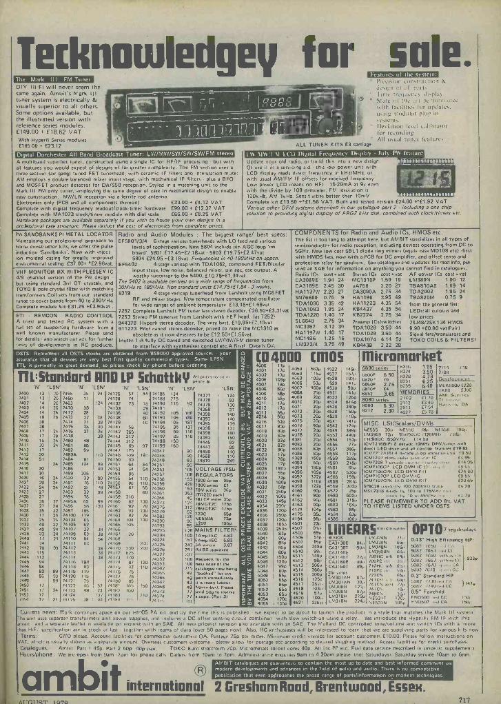
The Mark III FM Tuner DIY I-IiFi will never seem the same again. Ambit's Mark III tuner system is electrically & visually superior to all others. Some options available, but the illustrated version with reference series modules: £149.00 + £18.62 VAT With Hyperfi Series modules £185.00 + £23.12
Digital Dorchester All Band Broadcast Tuner: LW/MW/SW/SW/SW/FM stereo A multiband superhet tuner, constructed using a single IC for RF/IF processing but with all features you would expect.of designs of far greater complexity. The FM section uses a
three section lair gang) tuned FET tunerheacl, with ceramic IF filters and interstation mute; AM employs a double balanced mixer input stage, with mechanical IF filters plus a BFO and MOSFET product detector for CW/SSB reception. Styled in a matching unit to the Mark III FM only tuner, employing the same degree of care in mechanical design to enable easy construction. MW/LW reception via a ferrite rod antenna. Electronics only (PCB and all components thereon) £33.00 + £4.12 VAT Complete with digital frequency readout/clock-timer hardware £99.00 + £12.37 VAT Complete with MA1023 clock/timer module with dial scale £66.00 + £8.25 VAT Hardware packages are available separately if you wish to house your own designs in a
professional case structure. Please deduct the cost of electronics from complete prices.
ALL TUNER
` l'rcCi,inn con,lruclicm de,ign al II Il3'1, Ilnlc IrcyuCn:> II1,1111\
` Sl;ltr OE Iltc 1117 perinrlllanCe vsith (acilitic, lü u!xl;dC u,ing 1110(lulur !)lug in
Deviation level calihr,rlor li)r recording All u,uul tuner leaturc,
KITS £3 carriage
LW NI1ti T\I I( I) Digital Frequency Display - July PW feature 1lRRANrRRA Update your old radio, or build this into a new design.
Or use it as a servicing aid this low power unit with LCD display reads direct frequency in kHz/MHz, or with usual AM/FM IF offsets for received frequency. Low power LCD means no RFI 15-20mA at 9v even with the'divide by 100 prescalar. FM resolution is
100kH's, AM 16Hz. Sensitivities better than 10mV Complete kit £19.50 +*£1.56 VAT. Built and tested version £24.00 +"£1.92 VAT Various other DFM systems described in our catalogue part 2 - including a one chip solution to providing digital display of FRG7 kHz dial, combined with clock/timers etc.
PW SANDBANKS PI METAL LOCATOR Maintaining our professional approach to home constructor kits, we offer the pulse induction 'Sandbanks'. Now with inject- ion molded casing for greatly improved enviromental sealing. £37.00+'£2.96vat. VHF MONITOR RX WITH PLESSEY IC 4/9 channel version of the PW design but using standard 3r,1 OT crystals, and TOYO 8 pole crystal filter with matching transformers. Coil sets from our standard range to cover bands from 40 to 200MHz Complete module kit £31.25 +£3.90vat .
ETI - REMCON RADIO CONTROL A tried and tested RC system with a
full set of supporting hardware from a
well known manufacturer. Please send for details and watch our ads for further news of developments in RC products.
Radio and Audio Modules : The biggest range/ best specs: EF5801/3/4 6 stage varicap tunerheads with LO feed and various
levels of sophistication. New 5804 include pin AGC loop 'on board'. 5801:E17.45+£2.1 Bvat - 5803:£19.75+E2.47vat 5804:£24.95 +E3.18vat. Frequencies in 40-180MHz on appcn.
EF5402 4 stage varicap with TDA1062, compound FET/Bipolar input stage, low noise, balanced mixer, pin age, ose output. A worthy successor to the 5400. £10.75+£1.34vat
The 5402 is available centred on a wide range of frequencies from 30MHz to 180MHz. Non standard units £14.75+£1.84 - 3 weeks. 8319 4 stage varicap tunerhead from Larsholt using MOSFET
RF and mixer stages. New temperature compensated oscillator for wide ranges of ambient temperature £13.45+£1.68vat
7252 Complete Larsholt FM tuner less stereo decoder. £26.50+£3.31vat 7253 Stereo FM tunerset from Larsholt with FET head. (as 7252) 944378 Hyperfi stereo decoder. The very best. £19.95+£2.49var 911223 Pilot cancel stereo decoder, priced to make the MC1310 as
obsolete as it now deserves to be.E12.50+£1.56vat Inotec 1-A fully DC tuned and switched LW/MW/FM stereo tuner
to interface with s nthesiser control etc.A first! Details OA
COMPONENTS for Radio and Audio ICs, HMOS etc. The list is too long to attempt here, but AMBIT specializes in all types of semiconductor for radio reception, including devices operating from DC to 5GHz. New low cost SBL1 diode ring mixers (equiv case MD108 etc) -first with HMOS Pets, now with a PCB for DC amplifier, and offset sense and protection relay for speakers. See catalogue and updates for most info, pse
send an SAE for information on anything you cannot find in catalogues. Radio ICs cost n vat Stereo ICs cost r- vat AF power ICs cost r vat CA3089E 1.94 24 MC131OP 1.50 19 LM380N 1.00 12
CA3189E 2.45 30 uA758 2.20 27 TBA810AS 1.09 14
HA1137W 2.20 27 CA3090A 2.75 34 TDA2002 1.95 24 HA1196 3.95 49 TBA82OM 0.75 9 SN76660 0.75 9
TDA1090 3.35 42 TDA1083 1.95 24 TDA1220 1.40 17
SL6640 2.75 34 MC3357 3.12 39 HA1197W 1.40 17 MC1496 1.25 16 LM373/4 3.75 49
HA11223 4.35 54 KB4437 4.35 54 KB2224 2.75 34
Preamp ICs/switches TDA1028 3.50 44 TDA1029 3.50 44 TDA1074 4.14 52 K64438 2.22 28
from the general list: LEDs:all colours and low prices 2SJ48/2SK134 HMOS 9.90 +£0.80 vat(Pair) Signal fets/transistors and TOKO COILS & FILTERS!
OSTS: Remember all OSTS stocks are obtained from BS9000 approved sources . your assurance that all devices are very best f rst quality commercial types. Some LPSN TTL is presently in great demand, so please check by phone before ordering .
TTL:Standard 11110 LP Schottkli ponce*sl'srurl'n 'LSN' 'N' LSN' SN' 'N' 'LSN' 'LSN'
7400 13 7455 35 24 74126 57 44 74185 134 74377 124 7401 13 20 7460 17 741 8 74 74188 275 74378 93 7402 14 20 7463 124 741 2 73 78 74190 115 92 74379 130 7403 14 20 7470 28 741 3 29 74191 74368 37 7404 14 24 7472 28 74136 40 74192 105 180 74390 140 7405 18 26 7473 32 38 74138 60 74193 105 180 74393 140 7406 38 7474 27 38 741 9 60 74194 105 187 74395 139 7407 38 7475 38 40 741 1 56 74195 95 137 74396 133 7408 17 24 7476 37 38 741 2 265 74196 99 110 74398 180 7409 17 24 7478 38 741 3 312 74197 85 110 74393 150 7410 15 24 7480 48 741 4 312 74198 150 74445 92 7411 7412
20 17
24 7481 7482
86 69
74145 74141
65 175
97 74199 74247
160 90
74447 74490
90 140 7413 30 7483A 110 741 8 109 191 74248 90 74668 110 7414 51 7484 97 741 0 99 74249 93 74670 249
7415 24 7485 104 99 74151 64 84 74251 90 VOLTAGE /PSU 7416 30 7486 40 741 3 64 54 74253 105
7417 7420 7421 7422 7423 7425 7426 7427 7428 7430 7432 7433
30 16 29 24
'27 27 36 27 35 17 25 40
24 24 24
27 29 32 24 24 32
7489 7490 7491 7492 7493 7494 7495A 7496 7497 74100 74104 74105
205 33 76 38 32 78 65 58
185 119
63 62
90 110 78
99
99 120
741 4 741 5 7415? 741 7
74158 741 9 74160 74161 /4162 /4163 /4164 /4165
96 54 80 67
210 82 92 92 92
104 105
110 110
55 60
130 /8
130 /8
130
74257 74258 74259 74260 74261 74266 74273 74275 74279 74283 /4290 74293
108 153 420 153 353 40
124 312 52
120 90 95
REGULATORS 7800 series 95P 7900 series £1 78M series 90e 110220 pack) 78LCP series 35p 78MGT2C 175p 79MGT2C 175p 723C 65p NE550A 73p L200 195p
7437 40 24 74101 32 38 /416fì /4795 120 MAINS FILTERS 7438 33 24 74109 63 38 /410/ 20 /4298 100 )Amp SEC 4.83' 7440 17 24 74110 54 54 /4168 /4324 157 Amp 'EC 5.83 7441 /4 74111 lib /4169 200 /4325 242 5A wire., 3.87 7442 70 99 74112 38 /4110 230 200 14326 247 All BS approved 7443 115 74113 38 /4177 625 /4327 23/
Requests for the
xt issue of the
7444 7445
112 94
74114 74116 198
38 /41/3 /4l/4
1/5 8/ 120
/4352 74353
100 100
7446 94 74118 83 141/5 87 nu /431,2 /15 catalogue n w being 7447 82 89 74119 119 /41/6 /5 74365 49 "booked" for des. 7448 7449
56 99 99
74120 14121
115 25
74171 14ivo
)8 85
74366 74367
49 43
patch immediately .t is ready (about 7450 17 74122 46 57 14181 165 150 /4368 49 November). Please
7451 7453
17 17
24 /4123 /4124
8 /3 13/
/4182 /4183
10(1
710 /4.113 74314
77 77
send sop to rese e
e cope. (Part 3) ry
74,4 / 24 /4125 le 44 /4104 135 74 1/5 641
[0 4WD [ 4000 4001 4002 4006 4007 4008 4009 4010 4011 4012 4013 4014 4016 4017 4018 4019 4020 4021 4022 4023 4024 4025 4026 4027 4028 4029 4030 4031 4032 4033 4034 4035 4036 4037 4038 4039 4040 4041 4042 4043 4044 4045 4046 4047 4048 4049 4050 4051 4052 4053 4054 4055
17p 17p 17p
109p 18p Bop sap 58p 17p 17p
asp 52p 80p 80p 60p 93p 82p 90p 17p 76p 17p
180p 55p 72p
100p 58p
250p 10op 145p 200p 120p 250p 100p 105p 250p
83p 90p 85p 85p 80p
150p 13op 990 60p 55p 55p 65p 65p 65p
'120p 135p
4059 4060 4063 4066 4067 4068 4069 4070 4071 4072 4073 4075 4076 4077 4078 4081 4082 4085 4086 4089 4093 4094 4096 4097 4098 4099 4160 4161 4162 4163 4174 4175 4194 4501 4502 4503 4506 4507 4508 4510 4511 4512 4513 4514 4515 4516 4517 4518 4519 4520 4521
5630 115p 109p 53p
400p 250 20p 20p 20p 20p 20p 20p 90p 20p 20p 20P 200 82p 82p
150p 50p
190p 105p 372p 110p 122p 90p 90p 90p 90p
104p 95p 95p 23p 91p 69p 51p 55p
248p 991/
149p 98p
206p 2600 300p 125p 382p 103p 570
1091, 2368
05 4522 4527 4528
529 4530 4531 4532 4534 4536 4538 4539 4541 4543 4549 4553 4554 4556 4557 4558 4559 4560 4561 4562 4566 4568 4569 4572 4580 4581 4582 4583 4584 4585
1491, 1571, 1021/ 141p 90P 1411/ 1250 614p 380p 150p 110p 141p 174p 399e 440e 153,,
77p 386p 117p 388p 218e 65p
530p 159p 281p 303p 25p
600p 319p 164p 84p 63p
100p
Iilicromnrket 8216 1.95 2114 110 8224 3.50 8228 4.78 8251 6.25 8755 5.40 MEMORIES 2102 E1 70 2112 £340 2513 £754 4027 f5 78
6800 series 6800P 6.50 682ÚP f6 6850P 2.75 6810e E4 6852 3.65 8080 series 8080 6.30 8212 2.30
2/08 f
Development MEK6800 (720 TK8O E306 AMI, S'0".5cs Ti l'r e'.a, H.I,i,.,-1,. OA
MISC. LSI/Scalars/DVMs NE555 30p NE556 18+ NL558 1801' LM3909 72p 95H9(111(1 1320M11/ /Help I1C90DC /650M11/ 114 OU
ICM721681P1 8 decade 10MHr DFM/purer with direct LEO drive and all counter features £19.82 CM721 /6191 4 decade {o4,amui,al,le i11 E9 50 CM7207 clock nuke gci,c,./lu, IC E4 95 CM7208 7 decade co 1,r ,, Ii I'si,Iv ,I"v'" E 14 95 CM7106CP LCD DVMI IC 13'. 4'y01 £955 CM71O6CPK LCD DVM IT E2460 CM7107CP LED DVM IC E955 CM7107CPK LED DVM KIT £20fì5 848629 u,/'de by 100.200MH, sc..ri.,' £4 20 MSL2318 d'v'de 1/y 100 iv 1 75MH/ p ,, ,
d'v'de I,y 10 Ic 45M11/ "e" 14 70
PLEASE REMEMBER TO ADD 8% VAT TO ITEMS LISTED UNDER OSTS
LIIIEARSnpI, epn,nni,.'
BIMOS LM;124N /Ip 8 i, LM339N 1,6I' 90{, LM348N 1861'
LM3900N (illo 728 100HC 6,5 641u +0, 709PC ,111 :s61'
991, 71011I- 1"1, 1ì58 d 710PC ,l 591,
773CN 65 /4 1C11 101, 111,1'
/4111N Nbi 211' 74/CN /U1, 748CN 3(ip NE531T 17C,, NE5,11N IUS,'
CA;1130E CA3130T CA3140E CA3140T CA3160E CA3160r O0 LMH LM301AN LM3O8H LM308N LM318H LM318N
0'1/ IOP
1218 9 /p
2/91/ 2248
OPTO 7 seg display
0.43" High Efficiency HP: 5082 /650 0,1 1:A 5082 7653 0,1(31 5082 /1160 ,110.1-A 5082 /663 5082 /6/O e' CA 5032 76/3 ,I, ee,n CC
0.3" Standard HP 5082 //30 'eii l'A 5082 /140 ,1/'1 C(:
0.5" Fairchild FND500 ,1/d (:C 1500 FND50/ "v1 CA 1501,
233p
}1470
Current news: Work continues ap ce on our HMOS PA kit, and I y th urne this is published - we expect to be about to lau tch the product In a style that matches the Mark Ill system. The unit uses separate transformers and power supplies, and includes a DC offset sensing circuit combined with slow switch -on using a relay. We introduce the Hyper Fi FM IF with this advert and a separate leaflet is avail, hie on request with an SAE. All new pricelist revision also available with an SAE. The Mu lard DC contiolled tone/volume and switch ICs with a 'more Man HiFi' specification are in stock ; t last - togethe, with reams of data (over 50 pages now). Also, RC enthusiasts will be Interested to learn that we are supplying parts for various kits now Terms: CWO please. Account facilities for commercial customers OA. Postage 25p per order. Minimum credit Invoice for account customers £10.00. PI ase follow instructions on
VAT, which is usually shown as d separate amount Overseas customers welcome - please allow for postage etc according to de.,irecl shipping method. Access facilities for credit purchases. Catalogues: Ambit. Part 1 45p. Part 2 50p 90p paii. TOKO Euro shortform 20p. Micrometals toroid cores 40p, All inc PP etc. Full data service descrd ed in pricelist supplements. Hours/phone: We are open from Sam -7pm for phone calls. Callers horn 10am to 7pm. Administrative enquiries 9am to 4.30pm please (not Saturdays). Saturday service 10am ter 5pm.
AMBIT catalogues are guaranteed to contain the most up-to-date and best informed comment on
R modern developmentshat and advances in theo field of fapar and audio There am Ir publication that even apdroaches the broad range of parts/information on modern techniques.
international 2 Gresham Road, Brentwood, Essen. S 1lC 1lQT 1070 717

r> n 1 o 464*S?a e e tANGl+ ttenfror O Cl
Electronics Constructors - Our component packs save you money!
FREE: with the first order opened this month, worth £15 -A Rockwell
Calculator, value £10.95 PACK X101:- Contains
35 mixed capacitors - all good usable values, i,e.
1, 500pf/0.01 of/.01 of/.015uf etc. One pack for 45p or two packs for only 82p.
PACK X102:- Contains 50 Germanium Diodes - S 1 m to 0A91 40p per pack or
2 packs for only 77p
PACK X105:- Contains 50 mixed Wattage resistors.
Super value at 40p per pack or 2 packs for only 75p.
You can't lose on this pack. PACK X108:- Contains 20
electrolitic capacitors - ideal for transistor circuits. Values like 10mfd, 50mfd, 220mfd and 100mfd at £1
per pack or 2 packs for £1.75
PACK X103:- Contains 30 mixed transistors - some
new and branded - NPN & PNP silicon and Germanium (most usable) great value at
80p per pack or 2 packs for £1 PACKX104:- Contains 50
silicon diodes, Si m to 1N4148, a real bargain at 46p per pack or 2 packs
for 80p
PACK X107:- Contains 20 ceramic caps - ideal for transistor AF/RF circuits. Values like 150pf/270pf/ 330pf/22pf/39pf etc. Only
45p per pack or 2 packs for only 80p
PACK X108:- Contains 10 BC107, BC108,- BC109 (NPN) transistors all full
spec -devices at 95p per pack
SIGTRONIC S
* ELECTRONICS* 27 Malvern Street, Stap:hill, Burton -on -Trent, Staffs. DE15 912Y. Tel: (0283) 48888 after 8 pm.
Special orders and quotations. All prices include VAT. Add 40p to order for p & p. Cheques/PO's accepted.
44pM9h M0..el
Ì Piesse write pur Name end Address in block capitals
HOME RADIO (Components) LTD., Dept. RC 234-240 London Road, Mitcham, Surrey CR4 3HD
Regd. No. 912986. L.ondan
Wilmslow Audio
THE firm for speakers!
SEND 15p FOR THE WORLDS BEST CATALOGUE OF SPEAKERS, DRIVE UNITS KITS, CROSSOVERS ETC. AND DISCOUNT
PRICE LIST
AUDAXAUDIOMASTER *BAKER .BOWERS & WILKINS CASTLE CELESTION
CHARTWELL COLES DALESFORD DECCA EMI *EAGLE ELAC FANE
GAUSS GOODMANS I.M.F. ISOPON JR *JORDAN WATTS KEF
LEAK LOWTHER MCKENZIE .MONITOR AUDIO *PEERLESS RADFORD RAM
RICHARD ALLAN *SEAS .STAG .TANNOY VIDEOTONE eWARFEDALE *YAMAHA
SHACKMAN *TANGENT
WILMSLOW AUDIO DEPT REC
SWAN WORKS, BANK SQUARE, WILMSLOW CHESHIRE SK9 1 HF
Discount Hifi Etc. at 5 Swan Street and 10 Swan Street Tel: 0625-529599 for Speakers, 0625-526213 for HiFi
Profusely illustrated
128 A-4 size pages.
full -colour cover
Catalogue contains details of simple Credit Scheme
Price includes packing and postage
HOME RADIO (Components) LTD. Dept. RC, 234-240 London Road, Mitcham. CR4 3HD. Phone
718 RADIO AND ELECTRONICS CONSTRUCTOR

STEVENSON Electronic Components REGULATORS 78L05 30p 7805 60p 78L12 30p 7812 60p 78L15 30p 7815 60p
79L05 70p 79L12 70p 7905 80p
HARDWARE MINIATURE TRANSFORMERS 240 Volt Primary
Secondary rated at 100mA. Available with secondaries of:
6-0-6.9-0-9 and 12 - 0 - 12. 92p. each.
LOUDSPEAKERS 56mm dia. 8 ohms 70p 64mm dia. 8 ohms 75p 64mm dia. 64 ohms 75p 70mm dia. 8 ohms 100p 70mm dia. 80 ohms 110p
TERMINALS Rated at 10A. Accepts 4mm plug, black, blue, green, brown and red . . . 22p
SWITCHES Subminiature toggle. Rated at 3A 250V. SPDT 70p SPDT centre off 75p DPDT 80p DPDT centre off 95p
Standard toggle SPST 34p DPDT 48p
Wavechange switches. 1P12W, 2P6W, 3P4W or 4P3W all 43p ea.
Miniature switches (non -locking) Push to make 15p Push to break 20p
Slide switches (DPDT) Miniature 14p Standard
CONTROL KNOBS Ideal for Ilse on mixers etc. Fush on type with black base and marked position line. Cap available in red, blue, green, grey, yellow and black. 14p
7912 80p 7915 80p LM723 35p
WHY NOT VISIT OUR
NEW SHOP We welcome callers at our new premises at the address below (5 mins. from High St.) We are open Mon - Sat, 9am -
6pm. Special offers available.
Express telephone order service. Orders received be-
fore 5pm. are shipped first class on that day. Contact our Sales Office now! Tel: 01-464 2951/5770. 1
15p
S
SHORTLANDS MARKET SouARE
STATION
BROMLEY NORTH
STATION
9Q
O wIDMORRD
TiI BROMLEY SOUTH STATION
Quantity discounts on any mix TTL, CMOS, 74LS and Linear circuits: 100+ 10%, 1000+ 15%. Prices VAT inclusive. Please add 30p for carriage. All prices valid to April 1980. Official orders welcome.
BARCLAYCARD & ACCESS WELCOME.
Mail orders to: STEVENSON (Dept RE)
VISA
TRANSISTORS
AC127 AC128 AC176 AD161 AD162 8C107 BC108 BC109 BC147 BC148 BC149 BC148 BC177 BC178 BC179 BC182 BC182L BC184 BC184L BC212 BC212L BC214 BC214L BC477 8C478 BC479 BC548 BCY70
17p 16p 18p 38p 38p 8p 8p 8p 7p 7p Bp 9p
14p 14p 14p 10p 10p 10p 10p 1op 10p 10p 10p 19p 19P 19p 10p 14p
LINEAR THIS IS ONLY A SELECTION' 709 28p 741 16p 747 40p 748 30p CA3046 55p CA3080 70p CA3130 90p
BCY71 BCY72 BD131 BD132 BD135 BD139 BD140 BF2448 8F Y 50 BFY51 BFY52 MJ2955 MPSA06 MPSA56 TIP29C TIP30C TIP31C TIP32C ZTX107 ZTX108
14p 14p 35p 35p 38p 35p 35p 36p 15p 15p 15p 98p 20p 20p 60p 70p 65p 80p 14y 14p
ZTX109 ZTX300 2N697 3N1302 2N2905 2N2907 2N3053 2N3055 2N3442 2N3702 2N3704 2N3705 2N3706 2N3707 2N3708 2N3819 2N3904 2N3905 2N3906 2N4058 2N5457 2N5458 2N5459 2N5777
14p 16p 12p 38p 22p 22p 18p 50p
135p 8p 8P 9p 9p 99 8p
22p Bp 8p Bp
12p 32p 30p 32p 50p
DIODES 1N914 3p 1N5401 13p 1N4001 4p BZY88ser. 8p Full spec. product.
1N4148.£1.4oiloo. 611/1000
CA3140 38p LM301AN 26p LM318N 85p LM324 45p LM339 45p LM380 75p LM382 120p L M 1830 150p LM3900 50p LM3909 65p MC1496 60p MC1458 32p
CAPACITORS
NE555 21p NE556 50p NE565 85p NE567 170p SN76003 200p SN76013 140p SN76023 140p SN76033 200p SN76477 220P TBA800 70p TDA1022 650p ZN414 75p
TANTALUM BEAD 0.1, 0.15, 0.22, 0.33, 0.47, 0.68, 1 & 2.2uF @ 35V 4.7, 6.8, lout' @ 25V 22@ 16V, 47 @ 6V. 100@3V
MYLAR FILM 0.001, 0.01, 0.022, 0.033, 0.047 0.068, 0.1
POLYESTER Mullard C280 series 0.01, 0.015. 0.022, 0.033, 0.047, 0.068, 0
015,022 0.33, 0 47 0.68 1.0u F
each
Bp 13p 16p
3p 4p
1 5p 7p
10p 14p 17p
CERAMIC Plate type 50V. Available in E12 series from 22pF to 1000pF and E6 series from 1500pF to 0.047uF 2p
RADIAL LEAD ELECTROLYTIC 63v 0.47 1.0 2.2 4.7 10 5p
22 33 47 .7p 100 13p
220 20p
25V 10 22 33 47 5p 100 8p
220 10p 470 15p
1000 23p
VERO
Size in. 0.1 in. 0.15in Veropins- 2.5 x 1 14p 13p single sided 2.5 x 3.75 42p 40p per 100 2.5 x 5 52p 50p 0.1in 35p 3.75 x 5 60p 60p 0.15in 40p 3.75 x 17 195p 180p
Aluminium boxes with lid and screws
Length width height ALI 3 2 1 48p AL2 4 3 17, 58p AL3 4 3 2 65p AL4 6 4 2 70p AL5 6 4 3 85p AL6 8 6 2 116P
100V 200V 400V
4A 36p 42p 51p
BA
45p 53p 66p
Plastic -cased Thyristors Texas
12A 62p 68p 86p
CONNECTORS JACK PLUGS AND SOCKETS
screened unscreened socket 2.5mm 9p 13p 7p 3.5mm 9p t4p 8p Standard 16p 30p 15p Stereo 23p 36p t8p
DIN PLUGS AND SOCKETS plug chassis line
socket socket 2pin 7p 7p 7p 3pin 11p 9p 14p
5pin 180° 11p 10p 14p
Spin 240° 13p 10p 16p
1mm PLUGS AND SOCKETS Suitable for low voltage circuits, Red & black. Plugs: 6p each Sockets: 7p each.
4mm PLUGS AND SOCKETS Available in blue, black, green, brown, red, white and yellow. Plugs: 11p each Sockets: 12p each
PHONO PLUGS AND SOCKETS
Insulated plug in red or black . . 9p Screened plug 13p Single socket . . 7p Double socket 10p
TRpCS Plastic cased Triacs. Texas. All rated at 400V.
4A 70p 42A 90p 20A 185p 8A 80p 16A 95p 25A 215p
CMOS 4001 4002 4007 4011 4013 4015 4016 4017
12p 12p 12p 12p 28p 50p 30p 48p
4018 4023 4024 4026 4027 4028 4029 4040 4042 4046 4049
55p 12p 40p 90p 30p 48p 50p 60p 50p 90p 25p
4050 4066 4068 4069 4071 4081 4093 4510 4511 4518 4520
25p 35p 18p 12p 12p tap 45p 65p 65p 65p 60p
FULL DETAILS IN CATALOGUE!
SKIS
Low profile by Texas
8pm 8p 16 pin 11p 28.,pin 22p 14 pin 10p 24 pin 18p 40 pin 32p
Soldercon pins. 100.50P- 1000.370P
OPTO
LED's Red Green Yellow Clips
0.125m. 0.21n
TIL209 TIL220 TIL211 TIL221 TIL213 TIL223 3p 3p
DISPLAYS DL704 0.3 in CC DL707 0.3 in CA FND500 0.5 in CC
each 100+
9P 8P 13p 12p 13p 12p
130p 120p 130p 120p IOOp 80p
RESISTORS Carbon film resist- ors. High stability, low noise 5%.
E12 series. 4.7 ohms to 10M. Any mix: each 100+ 1000+
0.25W 1p 0.9p 0.8p 0.5W 1.5p 1.2p 1p
Special development packs consisting of 10 of each value from 4.7 ohms to 1 Meg -
ohm 1650 rest 0.5W £7.50. 0.25W £5.70.
METAL FILM RESISTORS Very high stability, low noise rated at '''5W
1%. Available from 51 ohms to 330k in E24 series. Any mix:
each 0.25W 4p 3.5p 3.2p
PLEASE.WRITE FOR YOUR FREE COPY OF OUR NEW 80 PAGE CATALOGUE OF COMPONENTS.
CONTAINS OVER OVER 2500 STOCK ITEMS.
100+ 1000+
76 College Road, Bromley, Kent, Englan

TRADE PAY A VISIT - THOUSANDS MORE ITEMS BELOW WHOLESALE PRICE. CALLERS PAY LESS ON MANY ITEMS AS PRICES INCLUDE POSTAGE. PRICES INCLUDE VAT AND ADDITIONAL DISCOUNT IN LIEU OF GUARANTEE.
COMPONENTS UNLESS SUFFICIENT ADDED FOR REGISTRATION OR COMPNSATION FEE POST
-j. ci âE Q
W Z
N = 5.
y > .E'
g o
Ti.,
'; > 0-0,;..i.,
E N o in Ze as
c.ì of
' a 3 - -N u,
o E e 2 o : E
y ' m
C 5 N
°N CO)'
o E _ E
'g >. 9 N
3 m o U mco - , >- .p â Elmo
ân
w >
`- E E
CO É E
° ° v a o
OFFERS CORRECT AT 25/8/79 APPLICABLE TO ORDERS RECEIVED DURING JULY. JAP 4 gang min. sealed tuning condensers 40p
VALVE BASES Printed circuit b/u 7p Chassis B7-B7G ... .. 11 p Shrouded Chassis 87G -88A 13p B12A tube. Chassis 89A ... ... 13p
Car type panel lock and key 65p
Transformer 9V 4A
ELECTROLYTICS Many others in stock 63- 200-300-450--
Up to 10V 25V 50V 75V 100V 250V 350 V 500V MFD
Speaker 6" x 4" 5 ohm ideal for car radio £1.55 £3.78 10 6p 7p 7p 10p 13p 15p 26p 32p 4;" diam. 30 52 .. .. .. £1.75 23" diam. 32 or 80 . .. .. .. £1.07' Aluminium Knobs
for shaft. Approx.
25 6p 7p 7p 10p 13p 18p 32p 37p 50 6p 7p 7p 12p 16p 23p 32p 37p
w 61 O a
o o I- 8 M
o 2 , O n
a â
TAG STRIP -6 way 5p 8 way 10p Single 2p 11
15 x 5OpF or 1000 + 300pF trimmers 35p
Â"' x e'" with indicator Pack of 5 95p
100 7p 8p 13p 15p 24p 26p --m 250 12p 13p 15p 22p 36p - ;£1.10 £1.30 500 13p 15p 22p 30p 55p - £1.48 £1.60'
-
BOXES - Grey polystyrene 61 x 112 x 31 mm, top secured by 4- self tapping screws 57p clear perspex sliding lid, 46 x 39 x 24 mm 15p. ABS, ribbed inside 5mm centres for P.C.B., brass corner inserts, screw down lid, 50 x 100 x 25mm orange 65p; 80 x 150 x 50mm ,black 97p; 109 x 185 x 60mm black £1.52.
'OIECAST ALI superior heavy gauge with sealing gasket, approx 6+" X 2e" x li" £1.50; 31" x 21" x 11" £1.25.
1000 16p 27p 50p 60p - £1.05 - - 2000 28p 47p 55p 93p £1.20 - - - As total values are too numerous to list, use this price guide to work out your actual requirements 8/20, 10/20, 12/20, 22/50. 47/25. Tub. Tant 24p each 1 b -32/275V, 100/150V, 100-100/275V 40p 50-50/385V, 2+2/200V non polar, 32-32-50/ 300V, 20-20-20/350V 0.1+0.1/500V AC 80p 200V, 100-200-60/300V £1.30 100-300-100-
,16/300V £1.85
u O O N
ú O
m 0 -aO
O w w
d d
ó ó
VARIABLE CAMM PROGRAMMER 10, 12 or 15 pole 2 way, 50VAC motor - series with 1 mfd, or 3k 10W or 15W pygmy bulb
SRS 100-0-100 micro amp null indicator Approx. x 2" }" x 1" £1.85 for mains operation. Ex equipment £4.32
INDICATORS-- SWITCHES
Pole Way Type 1 2 Slide 15p
RESISTORS i-'-,-1 watt ...1.1p 1 watt 3p
Bulgin D676 red, takes M.E.S. bulb 38p 12 volt, or Mains neon, red pushfit 23p R.S. Scale Print, pressure transfer sheet 12p
6 2 Slide 24p 2 1 Rotary Mains 28p
- Up to 15w w/wound 10p 1 or 2% 4 times price CAPACITOR GUIDE - maximum 500V
Up to 4+p. Up to 6p o u, /- N
' ri
w w
c°t
c 4.nut m g x
,- e o rn ,'
r u
Em
ui
m
)4=s 1.0 2
cr N
-
2 AlternatingMicro with roller 30 2 3 Miniature Slide 201) P 2 1 Toggle 42p,
Cinch 8 way std 0.1 5 pitch edge connector 251)
.01 ceramic .01 poly .013 up to .1 poly etc. 7p..1 2 up to .68 poll' etc. 8p. Silver mica up to 360pF 10p, then to
21p. 1 2 Sub -Min Toggle 75p 2 Alternating2A Mains Push li" hole) 43
- p 2 Alternating Slide i5P
S.P.S.T. 10 amp 240v. white rocker switch with neon. 1" square flush panel fitting 60p;
r. RELAYS
RS/Alma reed relay. 3k S2 18-30v d.c. coil, normally open .........609 oc1 tal
d.p.c.o. heavy duty
2,200pF 13p; then to .01 mfd 1/750 13p..01/1000, 8/20, .1/900, .22/900,
25/250 AC (600v/DC), 3/600 15p. 5/150, 10/150, 40/150 50p.
Many others and high voltage in stock. s
> â 3 E
- w 6 m
o
o 2,, y
1 pole 2 way 10 amp oblong clip in mains rocker appliance switch 38p Standard thumb -wheel switch 0-9 in 1248N
700L2, 11-13v Min, " Seated 2 P.C.O. £1.
a p.c.o. £1.20.
' SONNENSCHEIN/POWERSONIC DRI-FIT RE- CHARGEABLE SEALED GEL (Lead Antimony) BATTERY, 6V 1 amp.hr. (3f" x 2" x £3.70. or B.C.D., or Comp. 1242 also 2p Co ..£1.20
Standard Lever Key Switch D.P.D.T. locking POTS
Wirewound Log. Lin.,
37C)
6 amp. hr. (41" x 2" x 3") £7.60 Ex -equipment, little used.
plus D.P.D.T. and S.P.S.T. Heavy Duty non latching 82p
or carbon rota38p ry or slide. Single 30p with switchi
switch 0p Dua55p
1145m
CONNECTOR STRIP Belling Lee L1469, 4 way polythene. 9p each
AUDIO LEADS 3 pin din tO open end, li -yd, twin screened 45n.
Edgetype 10 fog 40p
Skeleton Presets 11 glass fuses 250 m/a or 3 amp (box of 12) 20p Bulgin 5mm Jack plug and switched socket (pair) 40 g p 1,5 pin din 180' to 2 -phono 70p
3 pole jack plug to tag ends, 4ft ... ... 45p Slider, horizontal or verti- cal standard or sulimin 8p Reed Switch 28mm, body length 11p
= ut
`°' 3 m
> .p 3 .n'
- ,i a m
t o '3 o
,
COMPUTER & AUDIO BOARDS/ASSEMBLIES VARYING CONTENTS INCLUDE ZÉNÉR, GOLD BOND,
THERMISTORS and V.D.R's
Aluminium circuit tape, * x 36 yards -self adhesive. For window alarms, circuits, etc. 95p SILICON, GERMANIUM, LOW AND HIGII POWER TRAN-
SISTORS AND DIODES, HI STAB RESISTORS CAPACI- Teas FIFCTROLYTICS. TRIMPOTS, ''o: CORES, CHOKES. INTEGRATED CIRCUITS, ETC.
cZl/2/6/11/14, KR22, KT150, VA1005/6/8/ 1010/1033/4/7/8/9 1040/
TV MAINS DROPPERS 5 assorted multiple units for 75p L
> `0
73 E 0 E m 5 O g
Yo 2 ,° e x w
â a; z U 9 4 - w z _
n t
o c m 2' `O
1' E E
<o o
3lb for £2 7lb for £3.70 '' _.
1053/5 /1066/7/ 1074/6/7 / 1082/6/ 100pF air -spaced tuning capacitor £1.30
5}" x 2f" Speaker, ex -equipment 3 ohm 66p 1k horizontal preset with knob 10 for 40 p
3- Tape Spools 5p 1" Terry Clips 5p 12 Volt Solenoid 40p
1091/6/7/8 / 1100/3/8/ 8602. Rod with spot blue/fawn/green. E299DDP120 / 218 / 224 / 338 / 340 / 350 / 352
2 Amp Suppression Choke 10p 3 x 2 x "` PAXOLINE 5 for 35p 4 x x "' J 10 for 15p PVC on MES bulb Holder 5 for 30p ENM Ltd. cased 7 -digit counter 21 x 11 x 11''
approx. 12V d.c. (48 a.c.) or mains £1.10 YF020 E220ZZ/02 KR150 All 22p E23 glass bead 85p
or metal clip VALVE RETAINER CLIP, adjustable 5 for 15p
q- -- Sub -miniature Transistor Transformer 35p Auto charger for 12v Nicads, ex -new '
equipment .. £5.19
YG150-5534 bead, KB13, , E299 DHP230, 116-121 401 (TH7. VA1104. OD10) 35p. R53 Glass £1.2Ò
Valve type output transformer 90p POT CORES with adjuster LA2508-LA2519 43p per pair
o m
nw 3 T
ó Q E ^
5,N N
<
Miniature 0 to 5mA d.c. meter alfprox i" diameter £1.25 RS Yellow Wander Plug Box of 12 ... ... 40p 18 SWG multicore solder ... ... 31p foot FSAPHIRE STYLII. 15 different; dual and single point, current and hard to get types. My mix £2.
16 Watt Power Amp. Module 35v 1A power required, giving 16 watt RMS into 8 i2 £3.45 REGULATÉD TAPE MOTOR Grundig 6V approx., 3" x 11", inc. shock absorbing
BRIAN J REED 161 ST. JOHNS HILL, BATTERSEA, LONDON SW11 1TQ
Open 10 a.m. till 7 p.m. Tuesday to Saturday. VAT receipts on request. Terms: Payment with order Telephone: 01-223 5016
carrier, or Jap 9V, 1-1" diam. £1.05 3.5mm metal stereo plug 30p Fane 8 ohm 3" sq. heavy duty communications speaker £1.60 RS neg. volt regulator 103, 306-099 (equiv. MPC900) 10A, 100 watt 4-30 volt. Adjustable short circuit .rotection. Normally £12.50+. £6.85
720 RADIO AND ELECTRONICS CONSTRUCTOR

d
SEMICONDUCTORS Full spec. by Mullard etc. Many others in stock AC126/128/176 26p BCY70/1/2 14p'
BCZ11 32p 80113 Sip BD115 35p BD116(BRC116T) £1.15 BD130V £1.50 FIE/131/2/3 40p BD135/6/7/8/9 35p B0137/138 match pr 82p BD140/142 35p BD201/2/3/4 92p 80232/3/4/5/8 56p BDX77 £1.15 BD437 68p BF/115/167/173 18p 13F178/9 23p B F 180/1 /2/3/4/5 18p
,BF194/5/6/7 Sp BF194A, 195C 8p 8E200 258 324 23p BF262/3 35p BF336/274 31p BFS28 Dual M_ fi osfet£1.1 8FT61 40p BFW10/11 F.E.T 481 BFW30 £1.15
ACY20 30p ACY29 22p AD161/2 match pr. 86p, ADZ12 £4.00p AF124/6/7 28p AF139 23p AF 178/80/81 35p AF239 35p ASY27/73 36p AU110/113 £2.50 BC107/8/9 + A/B/C Bp BC147/8/9 + NB/C 8p BC157/8/9 + NB/C 8p BC173 p
BC178N8 179B 14p BC182/184C/LC 11p BC 186/7 8C204 BC212 BC213L/2146/238 BC327/8 337/8 BC547/8 t NB/C B C 556/7/7 B/8/9 BCX32/36 BCY31 BCY40
13p 13p 10p 13p lip 15p 90p 56p
Amp Volt BRIDGE RECTIFIERS ' 1,600 BYX10 34p
140 OSH01-200 30p 5 100 Ex Equip 73p 0.6 110 EC433 20 5 400 Texas £1.10 21 100 I. R. 48p
31 100 B40C 3200 689
BFX12/29/30 23p BFX84/88.89 20p' BFY51 18p BFY90 57p BR101 34p BRY39/56 29p BSV64 38p BSV79/80 F.E.T.s 90p BSV81 Mosfet £1.00 BSX20/21/78 18p BSY40 30p BSY95A 14p BU204 f Mount Kit £1.85 BU208 £2.28 CV7042 (0C41/44
ASY63) 12p:
GET111/E112 45p 13p 23p.
£2.30 :369p
£1:85 £1.15
9p 35p', 67p 18p
18p
0C45(ME2) ON222 R2008B/2010B
'TIP30 TIS43 (2N2646) uA7805 ZT1486 ZTX300/341 2N393 (M14393) 2N456A 2N706A 2N918 2N929 2N987 45p 2N1484 £1.15 2N1507/2219 18p
RECTIFIERS Amp Volt
M1 1 1N4005/6 1
1N4007/BYX94 1
BY103 1
SR100 SR400 REC53A LT102 BYX22-200
,BYX38-300R BYX38-600 BYX38-900 BYX38-1200 BYX49-300R BYX49-600 BYX49-900
BYX49-1200 BYX48-300R BYX48-600 BYX48-900
BYX48-1200R BYX72-150R BYX72-300R BYX72-500R BYX42-300 1N5401 1N5402 MR856 BYX42-900 BYX42-1200 BYX46-300R° BYX46-400R' BYX46-500R' BYX46-600 BYX20-200 BYX52-300 BYX52-1200 RAS310AF
1.5 1.5 1.5 2 1
2.5 2.5 2.5 2.5 3 3 3 3 6 6 6 6 10 10 10 10 3 3 3 10 10 15 15 15 15 25 40 40 1.25
*Avalanche type
68 6/800 1250 1,500
100 400
1,250 30
300 300 600 900
1,200 300 600 900
1,200 300 600 900
1,200 150 300 500 300 100 200 600 900
1,200 300 400 500 600 200 300
1,200 1,250
5p 8p, Spp
9p 10p 18p 16p
OPTO ELECTRONICS Diodes Photo transistor
BPX40 . . , 57p BPX29 . . , 92p BPX42 . . . 92p OCP71 . . . 75p BPY10 , . , 92p
(VOLTIAC) L.E.D.'s BPY68 .2" Red 18p BPY69 . . . 92p TIL209 .125" Red
BPY77 14p
Wire end necns 9p Green 18p
2N1613 2N2401 2N21412 2N2483
,2N2904/5/6/7/7A .2N3053 2N3055 R.C.A. 2N3133/4062 2N3553 2N4037 2N5484 FET 2N5956 254141/2/360 258135/6/457 40250 (2N-31554)
24p 36R, 80p 2£W 1.80 18p 60p 24p 58p 39p 39p 87p 38p 24p 35p
CATALOGUE 38, 11 x 8 Ins Illustrated sheets, listing approx. 5,250 Items, photo printed on day requested, from constantly updated masters, to ensure latest stock position, 75p (re- fundable with orders) plus 24p s.a.e. or Zabel.
TgAN i-ORMERS Ferromag C core, Screens 95- 105 -1t5 -125-200-220-240v input output 17v }A.. x. 2 + 24-0-24v 1.04A+20v 1 S'A, these current ratings can be safely exceeded Dy
50%. £4.90 Cassette Dynamic Micro -1
phone with switch and twin' plug £1.80 Telephone Pickup. sucker with lead and 3.5 plug.70p
OTHER DIODES ' 1N916 Bp 1N4009 9p 1N4148 4p BA145 17p Centercel 29p BZY61 /BA 148/OA81 12p
'BB103/110 Varicap 24p BB113 Triple Varicap43p 8A182 16p 045/7/10 17p J3ZY88 up to 43 volV10p BZX61 11 volt 17p AA133 10p BZY96C 10V 34p BZY95C 33V or 15V 34p
RS Irravin high tempera-, ture wire, 19/0.16, minus 55° to 105°C, 600V 3A, white, black or red. Half trade price at 54p 10M coil.
PVC QUALITY TAPE Llsso 10m x 15mm grey
38p 33m x 33mm green
£1.13 Trimmer: Post stamp type 3-3OpF 1143 10-8OpF 1 9 p 30-140pF .. 23p
GARRARD GCS23T Crystal Stereo' Cartridge £1.20 Mono (Stereo compatible) Ceramic or crystal £1
Amp Volt THYRISTORS _40 BTX18-200 .
400 BTX18-300 .. 240 BTX30-200 , ,
4 500 .40506 35 500 BT107 6,5 500 BT109-500R/SCR957/BRC4444,. 20 600 BTA/92-600RM ,
25pPHOTO SILICON CONTROLLED SWITCH I 15 800 BTX95-800R Pulse Modulated ,
B p BPX66 PNPN 10 amp £1.151
80p 85 35p 42p 47p 80p 47p 80p 70p 92p 42p 52p 86p 38p' 18p 18p 24p. 92p
£1,07 £1.19 £1.75 £2.00 £2.30
72p £2.06 £2.90
48p
r, 3" red 7 segment LE,D. 14 D.I.L. 0-9 + D.P. display 1.9v 19m/a segment, common anode 95p RS 0,6ín, green , ,£225 Minitron 0.3in 3015F filament. £1 25
COY11B L.E.D. Infra red transmitter . .£1,15'
One fifth of trade
35p 41p 36p 80p
£1.14 £1.14 £3.40, £8.75
PAPER BLOCK CONDENSER 0.25MFD 800 volt 87p 1MFD 250 volt 54p 1M FD 400 volt bhp
TV KNOB Dark grey plastic for recessed shaft (quarter inch) with free shaft extension
89
Amp Volt TRIACS 25 900 BTX94-900 £4.50 25 1200 BTX49-1200 £6,75 Diode Characteristic, Equiv., and
Substitution Book 82p .Transistor equivalents and
substitution Book 1 38p Book 2 82p Chrome Car Radio facia 28p Rubber Car Radio gasket -
10p DLI Pal Delayline 90p Relay Socket miniature 2PCO . . 20p 28 pin d.i.l. socket low profile 38p Colour EHT Tray 3000/3500 . . £5.50 Nylon self-locking, 31" tie clips . 3p 1.5, 10. 22 or 750 µh choke ....12p 0-30, or 0-15, black pvc, 360° dial, silver digits, self adhesive 41" dia. 13p Mullard Semiconductor. Valve & Component Data Book 1976-78 . 50p
R.S. Battery Holder for 4 x HP/SP 11 30p
CHASSIS SOCKETS Car Aerial -1-1-p-, Coax 8p, 5 pin 180° 11p, 5 or 6 pin 240° din Bp, speaker din switched 13p, 3.5 mm switched 7p, stereo 1" jack enclosed 20p.
McMurdo PP108 8 way edge plug 12p Multicore Solder 1kg, 16 or 18 or 20 s.w.g. 60/40 05.00' 3 inch 8 - £1,1e,
New unmarked, or marked ample lead ex new equipment
ACV 1 7-20 10p TIC44 10p 2G240 35p 2G302
2G401 2N711 2N2926 2N598/9 2N1091 2N1302
ASZ20 ASZ21
BC186 BCY30-34 BCY70/1/2 BY 126/7 HG1005 HG5009 HG5079 178/9 M3 0A81 0A47 0A200-2 OC23 0C200-5 C106 THY
13p 24p 10p
5p 12p' 4p 40_ 4p
12p 4p 4p 4pp
24p 38p
28p £1.17
Op 8p
28p Op Sp
10p 10p
1N1907 £1.17 Germ. diode 2p 2N3055
Motorola 38p GET120 (AC128 in 1" sq. heat sink 22p GET872 15p 2S3230 94p TIS43 225p
MINIATURE EDGE METERS 100uA f.s.d., scaled 0.5. 12V Illuminated blue perspex front, 35mm x 14mm £3.45
2001,4 level meter, clear front. 10 x 18mm £1.20
VAT & POST PAID
SPECIAL OFFERS 2500 mfd. 40v _L 58p; 0.1 mfd. 350/560v
10 for 50p 10000 mfd. 15v
3 for £1.18 6800 mfd, 10v 3 for 90e.
32+32/275v 3 for 90p Iii i 32/2 75v 3 for 80p
8+8 mfd. 375v4 for 90p 1 mfd. non -polar
350v 10 for £1.19 25000 mfd. 25v 65p 12000/12v 3 for £i.18 G.E.C. 5% Hi -stab capacitors 013. 061, 066, 069, 075, 08
10 for 65p AY5 8300 10 for £6 BC5488 500 for £28.50 BC556 500 for £28.50' BCY71 500 for £43.50 80437 50 for £13.75
2N2906500 for £43.50 TBA920 10 for £11.50 Vero card handle
10 for 65p 62 ) 1W Resistor
2.000 for £6.75. ON222 (superior matched. BF181) 10 for £1.20 68 Volt 10 Watt Zone, Diodes ...5 for £2,50
JNTEGRATEP CIRCIHII 'TBA920 TCA270 £2.20 TAA700 £2.40 TBA800 £1.24 741/7490/7473 280. ttA702/LM3900 53p 709 74107/74122
40p 38p
SN76228N £2,03 5N76131/75110..£1.55 SN76013N/ND £1.40
TAD100 AMRF £1.22 CA3001 R.F. Amp £1,58 CA3132 74151 45p CD4069 2 TAA300 1 wt Amp£1.15 TAA550YorG 6 TAA263774LS192 09. TAA320 £12,15 7400/7401 lop 7402/4/10/20/30 16o 7414/74132N hep 7438/7474/7432 27p AY5 8300 7483/74S20 7493/CD4013- 41p'
LttMyt30gp0p 2N/2ÚV reg gtl.'I5o
L74154/TBA810 £,2 TBA5 500/745 1 1 2 £1.80 ZN414
HANDLE'S Rigid light blue nylon 61" with secret fitting screws 11p Belling Lee white plastic surface coax outlet box40p Miniature Axial Lead Ferrite Choke formers 5 for 13p RS 10 Turn pot 1% 250 50001K. £1.70
opper coated board 18,'," x 21" 40p'
Geared Knob 8-1 ratio. 11" diem., black 93p
KLPP. 25A 440v TERMINAL BLOCKS
Professional leaf spring clamp. twin with clip -over
cover 11p Strip of 4, 40A 440V 18p
£1
NO MORE TO ADD - Prices INCLUDE UK VAT and Post/Packing
M'NIMUM ORDER £3 OTHERWISE ADD 50% ALL ENQUIRIES,.ETC., MUST BE ACCOMPANIED FOR SMALL ORDER HANDLING COSTS (UNDER BY A STAMPED ADDRESSED ENVELOPE £1.00 TOTAL ALSO INCLUDE 9p S.A.E.)
AUGUST, 1979 721

THE MODERN BOOK CO WORLD RADIO TV HANDBOOK 1979 £9.15
THE RADIO AMATEUR HANDBOOK 1979 by ARRL Price £7.86 UNDERSTANDING AMATEUR RADIO by J. Rusgrove Price £4.25 SOLID STATE DESIGN FOR THE RADIO AMATEUR ay ARRL Price £6.00
THE A.R.R.L. ANTENNA BOOK by ARRL Price £4.25 FM AND REPEATERS FOR THE RADIO AMATEUR by ARRL Price £3.50 REPAIRING POCKET TRANSISTOR RADIOS by I. R. Sinclair Price £2.50 BEGINNER'S GUIDE TO RADIO by G. J. King Price £3.00 BUILDING & DESIGNING TRANSISTOR RADIOS -A BEGINNER'S GUIDE by R. H. Warring Price £3.30 OP -AMPS - THEIR PRINCIPLES AND APPLICATIONS by J. B. Dance Price £2.50 ELECTRONICS FAULT DIAGNOSIS by I. R. Sinclair Price £3.00
UNDERSTANDING DIGITAL ELECTRONICS by Texas Instruments Price £3.90 NEWNES RADIO & ELECTRONICS ENGINEER'S POCKET BOOK by Newnes Price £2.80 BEGINNER'S GUIDE TO TAPE RECORDING by I. R. Sinclair Price £3.20 BEGINNER'S GUIDE TO AUDIO by I. R. Sinclair Price £3.00 BEGINNER'S GUIDE TO INTEGRATED CIRCUITS by I. R. Sinclair Price £3.00 BEGINNER'S GUIDE TO COLOUR TV by G. J. King Price £2.50 BEGINNER'S GUIDE TO ELECTRIC WIRING by F. Guillou Price £2.50 THE OSCILLOSCOPE IN USE by I. R. Sinclair Price £2.75 THE CATHODE-RAY OSCILLOSCOPE AND ITS USE by G. N. Patchett Price £4.00 INTRODUCING AMATEUR ELECTRONICS by I. R. Sinclair Price £1.50
" PRICES INCLUDE POSTAGE "
ABC'S OF ELECTRONICS by F. J. Waters Price £4.15 BEGINNER'S GUIDE TO HOME COMPUTERS by M. Grosswirth Price £3.20 ADVENTURES WITH ELECTRONICS by T. Duncan Price £2.85 PROJECT PLANNING & BUILDING by M. A. Colwell Price £2.20 110 COSMOS DIGITAL IC PROJECTS FOR THE HOME CONSTRUCTOR by R. M. Marston Price £3.00 110 OPERATIONAL AMPLIFIER PROJECTS FOR THE HOME CONSTRUCTOR by R. M. Marston Price £2.75 TESTING METHODS AND RELIABILITY ELECTRONICS by A. Simpson Price £4.30 DIGITAL ELECTRONIC CIRCUITS AND SYSTEMS by N. M. Morris Price £4.30 BEGINNER'S GUIDE TO MICROPROCESSORS by C. M. Gilmore Price £4.75 GETTING ACQUAINTED WITH MICROCOMPUTERS
by L. Frenzel Price £7.00 We have the Finest Selection of English and American Radio Books in the Country 19-21 PRAED STREET (Dept RC) LONDON W2 1NP
7 e/epnone: U1-402 9176
BUILD YOUR OWN. 40MHz Counter 300MHz Prescaler Rx Digital Readout
DIGITAL FREQUENCY COUNTER Model RQ-3 and its accessories offer you one of the most versatile combinations available. On Its own the RQ-3 in- corporates the following features: Mains operation - 40M Hz Counting -6 digit accuracy - 35mV RMS sensitivity - Displays not only FREQUENCY
IMHz1, but PERIOD (pS) and WAVELENGTH (Metres) es web - Complete Kit £44.95 + 15% VAT
RX DIGITAL READOUT Model RQ-3uM. Small additional PCB enables you to modify the RQ-3 Counter to correct for any IF and give you a display of Rx tuning frequency. Makes your inaccurate tuning dial obsolete)
Complete Kit £9.9íS + 15% VAT VHF PRtSOALER Model HQ -10 Self-contained in its own case witn its own power supply. Extends the range of any Frequency Counter to beyond
300M Hz. Complete Kit £18.95 + 15% VAT
SIGNAL CLARIFER Model RQ-a. irury remarxau,e multi -function filter and limiter plugs into the output of any receiver and fantastically improves signal readability by suppressing all types of interference. Contains HP, LP, BP and
Notch filters in various combinations. Remarkable value at only £22.60 + 15% VAT
CRYSTAL CALIBRATOR model RQ-1. Outputs on 1MHz, 100kHz and 10kHz either CW or internally modulated wjth audible tone. Gives harmonics well into VHF.
Complete Kit only £12.72 + 15% VAT
BEGINNERS SHORT WAVE RADIO Model RQ-5. Sensitive little radio. Ideal for the budding Dx-er of any age. Reception from all over the world
guaranteed. Kit includes a helpful guide to Dx-ing. Complete Kit £10.60 + 15% VAT
MORSE PRACTICE KIT Model RQ-7. Includes key and all necessary com- ponents including case and PCB. Ideal beginner's kit.
Complete Kit £9.50 + 15% VAT bend for details - postage appreciates), 9p stamp
Rocquaine electronics
Aldebaran, Le Coudre Rocquaine
GUERNSEY C.I.
vero
L OF OV P
ußNG P CPG
e00 P34) PN
Our new catalogue lists a whole range of plastic boxes to house all your projects. And we've got circuit boards, accessories, module systems, and metal cases - everything you need to give your equipment the quality you demand. Send 25p to cover post and packing and the catalogue's yours.
VERO ELECTRONICS LTD. RETAIL DEPT. Industrial Estate, Chandlers Ford, Hants. SO5 3ZR
Telephone Chandlers Ford (04215) 2956
722 RADIO AND ELECTRONICS CONSTRUCTOR
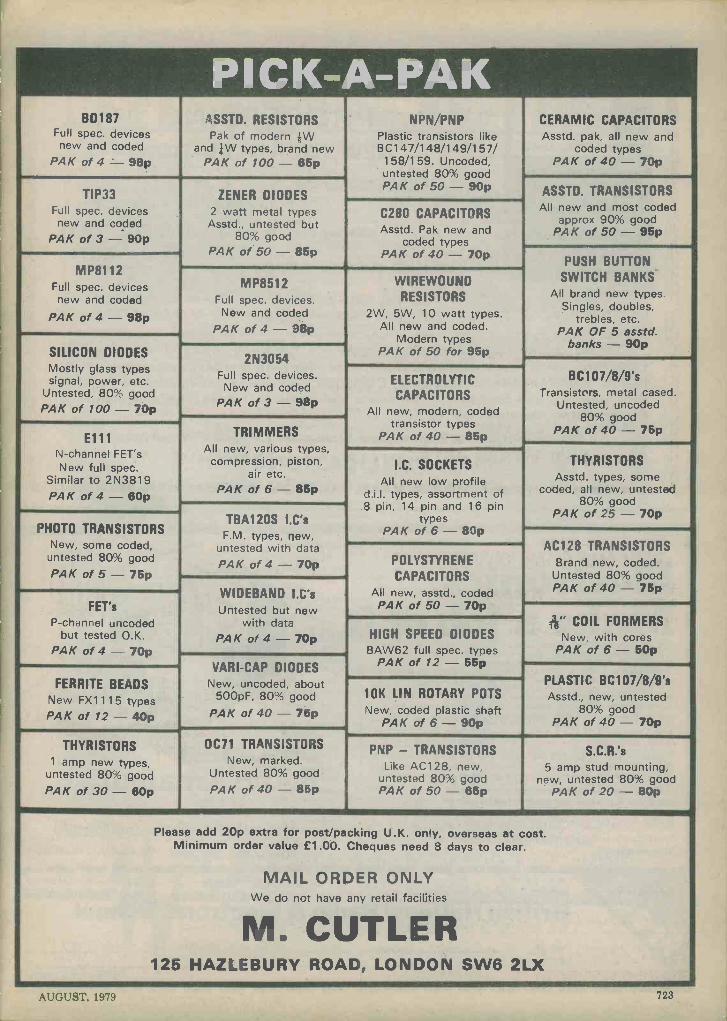
PI C K-A-PAK BD187
Full spec. devices new and coded
PAK of 4 = 98p
ASSTD. RESISTORS Pak of modern kW
and +W types, brand new PAK of 100 - 65p
TIP33 Full spec. devices new and coded
PAK of 3-90p
MP8112 Full spec. devices
new and coded
PAK of 4 - 98p
ZENER DIODES 2 watt metal types Asstd., untested but
80% good PAK of50-85p
NPN/PNP Plastic transistors like BC 147/148/149/157/ 158/159. Uncoded, untested 80% good PAK of 50 - 90p
CERAMIC CAPACITORS Asstd. pak, all new and
coded types PAK of 40-70p
C280 CAPACITORS Asstd. Pak new and
coded types PAK of 40 - 70p
ASSTD. TRANSISTORS All new and most coded
approx 90% good PAK of 50-95p
SILICON DIODES Mostly glass types signal, power, etc.
Untested, 80% good PAK of 100 - 70p
MP8512 Full spec. devices.
New and coded PAK of 4 - 98p
2N3054 Full spec. devices.
New and coded PAK of 3 - 98p
WIREWOUND RESISTORS
2W, 5W, 10 watt types. All new and coded.
Modern types PAK of 50 for 95p
PUSH BUTTON SWITCH BANKS
All brand new types. Singles, doubles,
trebles, etc. PAK OF 5 asstd.
banks - 90p
E111 N -channel FET's New full spec.
Similar to 2N3819 PAK of 4 - 60p
TRIMMERS All new, various types,
compression, piston, air etc.
PAK of 6 - 85p
ELECTROLYTIC CAPACITORS
All new, modern, coded transistor types
PAK of 40 - 85p
BC 107/8/9's Transistors, metal cased.
Untested, uncoded 80% good
PAK of 40 - 75p
PHOTO TRANSISTORS New, some coded, untested 80% good PAK of 5 - 75p
TBA120S I.C's F.M. types, new,
untested with data
PAK of 4 - 70p
I.C. SOCKETS All new low profile
d.i.l. types, assortment of 14 pin and 16 pin
types PAK of 6 - 80p
THYRISTORS Asstd. types, some
coded, all new, untested 80% good
PAK of 25 - 70p
FET's P -channel uncoded
but tested O.K. PAK of 4 - 70p
WIDEBAND I.C's Untested but new
with data PAK of 4 - 70p
FERRITE BEADS New FX1115 types PAK of 12 - 40p
THYRISTORS 1 amp new types,
untested 80% good PAK of 30 - 80p
VARI -CAP DIODES New, uncoded, about
500pF, 80% good
PAK of 40 - 75p
0071 TRANSISTORS New, marked.
Untested 80% good
PAK of 40 - 85p
i
POLYSTYRENE
CAPACITORS All new, asstd., coded PAK of 50-70p
AC128 TRANSISTORS Brand new, coded.
Untested 80% good PAK of 40 - '75p
HIGH SPEED DIODES BAW62 full spec. types
PAK of 12 - 55p
;36" COIL FORMERS New, with cores
PAK of 6 - 50p
10K LIN ROTARY POTS
New, coded plastic shaft PAK of 6 - 90p
PLASTIC BC107/8/9's Asstd., new, untested
80% good PAK of 40 - 70p
PNP - TRANSISTORS Like AC128, new,
untested 80% good PAK of 50 - 85p
S.C.R.'s 5 amp stud mounting,
new, untested 80% good PAK of 20-80p
Please add 20p extra for post/packing U.K. only, overseas at cost. Minimum order value £1.00. Cheques need 8 days to clear.
MAIL ORDER ONLY We do not have any retail facilities
M. CUTLER 125 HAZLEBURY ROAD, LONDON SW6 2LX
AUGUST, 1979 723

Brochure without obligation to
PRICE £2.75 P. & P. 35p
British National Radio & Electronic School P.O. Box 156, Jersey, Channel Islands.
NAME
DATA PROCESSING
UNDERSTAND DATA PROCESSING
NEW FOURTH EDITION DATA PROCESSING, by Oliver & Chapman, is now in its Third Edition - first published1972.
200 pages 9*" x 6-1"
PUBLISHED BY D. P. PUBLICATIONS The primary aim of this outstanding manual is to provide a simplified approach to the understanding of data processing (previous knowledge of the subject is not necessary). The 40 chapters and appendices cover the following topics: Introduction to Data Processing; Organisation and Methods; Conventional Methods; Introduction to EDP and Computers; Hardware; Computer Files; Data Collection and Control; Programming and Software; Flowcharts and Decision Tables; Systems Analysis; Applications; Management of EDP, etc.
A must for Business and Accountancy Students
DATA PUBLICATIONS LTD., 57 MAIDA VALE, LONDON W9 1SN.
Available from:
Electronics. Make a job of if.... Enrol in the BN A & E School and you'll have an entertaining and facinating hobby. Stick with it and the opportunities and the big money await you, if qualified, in every field of Electronics today. We offer the finest home study training for all subjects in radio, television, etc., especially for the CITY AND GUILDS EXAMS (Technicians' Certificates); the Grad. Brit. I.E.R. Exam; the RADIO AMATEUR'S LICENCE; P.M.G. Certificates; the R.T.E.B. Servicing Certificates; etc. Also courses in Television; Transistors; Radar; Computers; Servo -mechanisms; Mathematics and Practical Transistor Radio course with equipment. We have OVER 20 YEARS' experience in teaching radio subjects and an unbroken record of exam successes. We are the only privately run British home study College specialising in electronics subjects only. Fullest details will be gladly sent without any obligation.
Become a Radio Amateur. Learn how to become a radio -amateur in contact with the whole world. We give skilled preparation for the G.P.O. licence.
MOOR IMO MOM UM MOM IMMMO OMB BIM MIMI @OM MOM ti WWI IBM MI= REL 8/79
ADDRESS
Block caps please BIM - - RIM M M M M 1111111 I = M 111111M - i i
724
RADIO AND ELECTRONICS CONSTRUCTOR

STABILIZED POWER SUPPLIES WITH ELECTRONIC SHORT CIRCUIT PROTECTION
AL.212 P
PEL... / AL22P..
Ar
é
£14.75
INPUT VOLTAGE 220 V ac ± 10% 50-60 Hz OUTPUT VOLTAGE RANGE 12,6 V dc OUTPUT CURRENT MAX 2,5 Amp LOAD REGULATION <0,3% 0-2,2 Amp RIPPLE <5mV 2,2 Amp DIMENSIONS (mm) W140 x H90 x D140 WEIGHT 1,490 Kg.
AL.315
ME P úèW!
£29.50
INPUT VOLTAGE
P
,, it T4F 1a
220 V ac i 10% 50-60 Hz OUTPUT VOLTAGE RANGE 1,7-15 V. dc LOAD REGULATION <0,2 % 0-2,8 Amp DIMENSIONS (mm) W140 x H90 x D155 RIPPLE 3mV 2,8 Amp WEIGHT 2,330 Kg.
AL.330 P
1
£46.50 INPUT VOLTAGE 220 V ac ± 10% 5060 Hz OUTPUT VOLTAGE RANGE 3,4=30 V. dc OUTPUT CURRENT RANGE MAX 3 Amp LOAD REGULATION < 5% 0-2 8 Amp RIPPLE 10mV 2,8 Amp DIMENSIONS (mm) W270 x H90 x D155 WEIGHT 4,250 Kg.
Distrl Muted in the U.K.
and Ire anc
STOCKISTS Alpha Sound Service, 50 Stuart Road, Waterloo, Liverpool L22 40T. England.
Anson Electronics, 1133 Hessle High Road, Hull, England.
Amateur Radio Shop, 13 Chapel Hill, Huddersfield, HD1 3ED. England.
Brent Electronics, Seaview Street, Cleethorpes, Lincolnshire, England.
J. Birkett, 26 The Strait, Lincoln, England.
Bradford Consultants Limited, 25 Regent Parade, Harrogate, Yorkshire, England.
F. Brown & Co. Ltd., 44/46 George IV Bridge Street, Edinburgh, Scotland.
N. R. Bardwell Limited, Sellers Street, Sheffield, England.
Casey Brothers, 235 Boundary Road, "Saint Helens," Lancashire, England.
Electronic Services Limited, 33 City Arcade, Coventry CU11 HX, England.
A. Fanthorpe Limited, 6 Hepworth Arcade, Silver Street, Hull, England.
G. W. M. Radio, Portland Road, Worthing, Sussex.
Leeds Amateur Radio, 27 Cookridge Street, Leeds LS2 3AG, England.
Target Electric Limited 16 Cherry Lane, Bristol, England.
New Cross Radio, 6 Oldham Road, Manchester, England.
Progressive Radio, 93 Dale Street, Liverpool L2 2JD. England.
R. E. Pitt Electrical Services Limited, 60/64 Bath Buildings, Mont Pelier, Bristol, England.
Peats Electronics, Parnell Street, Dublin.
R. F. Potts, 68 Bobbington Lane, Derby, England.
Brian A. Pearson Limited, 66 Moncur Street, Glasgow, Scotland. R M E Supplies Limited, 143 Stockwell Street, Glasgow, Scotland.
Stephan James Limited, Warrington Road, Leigh, Lancashire.
Stewarts Radio, 4 Chance Street, Blackpool, England.
The Radio Shop, 16 Cherry Lane, Bristol BS 3NG, England.
Q. C. Trading, 1 St. Micheals Terrace, Woodgreen M22 4FT, England.
AL.1 P5
-,
f
£78.00
INPUT VOLTAGE 220 ± 10% 50 Hz OUTPUT VOLTAGE RANGE 1 t 15 V. dc OUTPUT CURRENT MAX 5 Amp LOAD REGULATION < 0,1% 0-45 Amp RIPPLE < 2mV 4,5 Amp DIMENSIONS (mm) W210 x H155 x 0250 WEIGHT 5,100 Kg.
AL.212 PS
at
Maxiasa -& ._
£18.00 INPUT VOLTAGE 220 V ac ± 10% 50-60Hz OUTPUT VOLTAGE RANGE 12 6 V dc OUTPUT CURRENT MAX 2 5 Amp LOAD REGULATION <0,3% 0-2,2 Amp RIPPLE <5mV 2,2 Amp DIMENSIONS (mm) W140 x H90 x 0140 WEIGHT 1,490 Kg. AMPSROMETER
AL.315 P2
l
£54.00
INPUT VOLTAGE 220 V ac ± 10% 50-60 Hz OUTPUT VOLTAGE RANGE ± 1,7 ± 15 V dc OUTPUT CURRENT RANGE MAX 3 Amp LOP D REGULATION < 0,2% 0-2,8 Amp RIPPLE < 3mV 2,8 Amp DIMENSIONS (mm) W270 x H90 x D155 WEIGHT 4,140 Kg.
Stan WIIIets Limited, 37 High Street, West Bromwich.
M/S Waltons, 55a Worchester Street, Wolverhampton WV2 4LL, England.
PEAT'S WHOLESALE LT
Chapel Lane, Parnell St.,Dublin l,lrelanc PHONE 741746-740678-722845. TELEX 31787.
AUGUST, 1979 725

THE "DORIC" 9 WAVEBAND
PORTABLE
Part 1
By Sir Douglas Hall, Bt., K.C.M.G.
This opening article describes a complete 6 -waveband short wave receiver, to which can be added amplifier and a tuner covering v.h.f., medium and long waves.
This 4 part series describes a multi -band por- table receiver which offers six bandspread short wave ranges covering 13.5 to 52 metres, medium waves, long waves and v.h.f. on Band II. The design can be built in stages, each stage resulting in a com- plete receiver or amplifier in its own right. The first part of the series commences by dealing with the short wave section which, when assembled, consists of a receiver suitable for use on its own with headphones. The following parts of the series will describe the addition of an amplifier and speaker to this short wave receiver, and further steps which provide for the reception of medium wave, long wave and v.h.f. signals. SHORT WAVE CIRCUIT
The circuit of the short wave headphone receiver appears in Fig.l. The aerial signal is applied via Cl and VR1 to the emitter of TR1. VR1 is a selectivity control, and can also be used as a vernier reaction control. TR1 amplifies as a common base device, the signal at its collector being passed via C3 to the base of TR2 which, at r.f., is a common collector amplifier. Detection takes place at D1, and the consequent audio signal then passes through TR2 again, working now as a common base amplifier, followed by TR1 as a common emitter amplifier with some negative feedback due to the presence of VR1.
726
Variable inductance tuning is used, band setting being arranged by having a ferrite rod move into coil L2, the rod movement being controlled by the six positions of rotary switch Sl. This has a tuning drive drum fitted to its spindle, and a nylon cord on the drum controls the amount of insertion into the coil of the ferrite rod. At the same time, one set of the switch contacts varies the parallel capacitance across the diode, to give optimum results for each position of the ferrite rod. The associated capacitors, C5 to C8, allow reaction in the Colpitts mode to be obtained. Reaction control is given by varying the impedance of the diode, and hence the damping on the tuned circuit, by altering the direct current which passes through the diode. Panel con- trol VR2 varies this current (which is additional to that passing through TR2) and thereby controls reaction. VR3 is adjusted to compensate for different gain levels in the transistor used in the TR2 position, and D2 and D3 provide voltage stabilization as battery voltage falls with age.
The a.f. output is built up across the large win- ding of the interstage transformer Ti, and high resistance phones (4,00012 magnetic or crystal) may be plugged into the lower jack socket. The up- per socket is unused with the receiver in its present state of"construction, and will be employed when the amplifier to be described next month is added.
RADIO AND ELECTRONICS CONSTRUCTOR

Telescopic aerial
T1
000§n.-. eaaol~-
5 t9V BI
CIO
C3
VR1
TRI
BF 115
Screen (not used)
0 0
BF 115
Lead-outs
Upper jack socket V
o
TR2
BFI 15
DI
!si
R4
Co
1I
C12
AV
Lower jack socket
VR2
R5
A g-.V Co
Jack socket connections
T.C6
C7
C8 T
C5 D2 +
ir D3 +
Fig. 1. The circuit of the multi -band short wave receiver. High impedance headphones are plugged into the lower jack socket whilst the upper jack socket a//c ws interconnection to the amplifier unit which will be described next month. L2 is permeability tuned by a ferrite rod moving to six positions inside the coil, these positions being mechanically controlled by switch
sl
Resistors (All fixed values ; watt 10%)
R1 1k U
R2 33k u R3 12k R4 1.2k c R5 8.2k c1
VR1 470 c potentiometer, linear, type P20 (Elec- trovalue)
VR2 4.7k c potentiometer, linear, with switch S2, type P20 (Electrovalue)
VR3 470 c pre-set potentiometer, 0.25 or 0.3 watt, horizontal
Capacitors C1 100pF silvered mica or ceramic C2 1,000pF silvered mica or ceramic C3 5.6pF silvered mica or ceramic C4 471.LF electrolytic, 3V. Wkg. C5 220pF silvered mica or ceramic C6 220pF silvered mica or ceramic C7 330pF silvered mica or ceramic C8 100pF silvered mica or ceramic C9 0.4712F polyester C10 2,200pF silvered mica or ceramic C11 47µF electrolytic, 3V Wkg. C12 1,000 µ F electrolytic, 10V.Wkg. VC1 15pF variable, type C804 (Jackson)
Inductors L1 2.5mH r.f. choke (Repanco) L2 see text T1 transformer type LT44 (Eagle)
Semiconductors TR1 TR2 D1 D2
BF115 BF115 0A90 or 0A91 1S44
9V
D3 1S44 Switches
S1 2 -pole 6 -way rotary, miniature S2 s.p.s.t. toggle, part of VR2
Sockets 2 -off 3.5mm. jack sockets
Aerial Telescopic aerial type TA10 (Eagle-Electrovalue)
Miscellaneous 10 -way tagstrip (see text) 4 control knobs Ferrite rod, 4 or 4 in. by 3/8in. dia (see text) 1;. drive drum (Home Radio)
9 -volt battery type PP3 Battery connector Nylon cord Materials for case and
"chassis" assembly
AUGUST, 1979 727

^ 21/2" _. 21/2' . 2112' 23/4'
51/2"
oD E
1/8"S.R.B.P
AO
11/4" 11/4"
BO I
F 0 Go
AB.0 3/8" D.E.FG 3/32"
(a)
25 turns 26 s.w.g.
en. wire
Dowelling
(I/4"
11/2"
Plastic clamp
21/2" ferrite rod
-j 5/Bo
I/8"hole (for bolt at hole R)
(f)
3/g`
1/2.,
L° 0
M O° P
/4"
oN
1/8"S.R B.P
HO
JO
K R o o
S o
H.K 5/32" J 1/4"
L.N.0.5 3/32' M.PR 1/8"
(b)
i 1/4 !,.
jt 11/4"
l'
5/32'
0
Q
o
5/32'
/8
I/8 SRBP.
-"I 3/4"
(g)
21/2'
21/2"
Solder tag --
Fig.2g
1/4 *ply 5/g`
1/2"
(c)
1/4'"ply
4 BA nuts
Í 4BA nuts
(h)
T 1/2'
(d)
11(48A csk bolt (hole H )
I1/4"drum
Fig.2b
Hole K
1 314"
21/2"
PP3 battery
Fig.2a
10- way tagstrip
W X
1/8"S R B
5/g"
óOZA
ov oZB
z 0
U.VI/4" W.XY.Z
ZA ZB 5/32"
(e)
(j)
Fig. 2(a) (b) (c) (d) (e). Section of the receiver "chassis" and case (f) Details of the coil, in which the ferrite rod slides to give selection of the six waveranges (g) S.R.B.P. item onto which switch S1 is secured (h). The drive drum is fitted over the spindle of the switch, the spindle passing through hole J of Fig. 2(b) (i) Side view showing the internal assembly of the main
parts of the receiver
CONSTRUCTION Construction commences with the cutting out
and drilling of the sections shown in Fig. 2(a) (b) (c) (d) and (e). These provide both the "chassis" and five sides of the case. A second piece of s.r.b.p. should be cut out identical to Fig. 2(e) but without holes U, V, ZA and ZB. This can be fitted opposite Fig. 2(e), forming the sixth side of the case, and can be the side which opens to provide access to the in- side of the completed receiver. The small holes, D, E, F, G, and the corresponding four holes in Fig. 2(b) and Fig. 2(e) are for woodscrews used to assemble the parts together. Their exact position- ing is not important provided that they are kin. from the ends. The woodscrews then pass into the ;in. plywood edges. The sixth opening side could, instead, be fastened by short lengths of 6BA stud- ding cemented into the plywood, 6BA terminals then securing the side in position. Holes W, X, Y and Z in the sixth side will then need to be *in. in diameter. Holes ZA and ZB are' for mounting the 10 -way tagstrip, the latter being used to mark out their positions.
The coil is made next. Take a piece of Fablon, or Contact, 4in. by 2kin., and remove a small strip of
51/2'
3/32"
Fig. 2c
Cord
Clamp
Ferrite rod
Fig. 2b
Coil
Fig.2d
Looking into the receiver with coil L2 nearer the Camera
728 RADIO AND ELECTRONICS CONSTRUCTOR
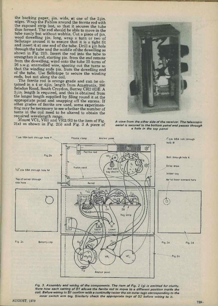
the backing paper, +in. wide, at one of the 2zin. edges. Wrap the Fablon around the ferrite rod with the exposed strip last, so that it secures the tube thus formed. The rod should be able to move in the tube easily but without wobble. Cut a piece of sin. wood dowelling zin. long, wrap a turn or two of Sellotape around it to ensure that it is a tight fit and insert it at one end of the tube. Drill a iin hole through the tube and the middle of the dowelling as shown in Fig. 2(f). Insert the rod into the tube to strengthen it and, starting +in. from the end remote from the dowelling, wind onto the tube 25 turns of 26 s.w.g. enamelled wire, spacing out the turns so that the winding ends *in. from the dowelling end of the tube. Use Sellotape to secure the winding ends, but not along the coil.
The ferrite rod is orange grade and can be ob- tained in a 4 or 4zin. length from Amatronix, 396 Selsdon Road, South Croydon, Surrey CR2 ODE. A 2zin. length is required, and this is obtained from the longer length supplied by filing round it at the appropriate point and snapping off the excess. If other grades of ferrite are used, some experimen- ting may be necessary to see whether the number of turns in the coil need to be altered to obtain the required wavelength range.
Mount VC1, VR1 and VR2/S2 to the item of Fig. 2(a) as shown in Fig. 2(i) and Fig. 3 A piece of
l'csk 6BA bolt through hole P
Fig. 2b
1/2"csk 6BA through hole M
Top of aerial through this hole
Fig. 2c Battery clip
Plastic clamp Anchor point
A view from the other side of the receiver. The telescopic aerial is secured to the bottom panel and passes through
a hole in the top panel
NI '' IIII I II '
I
Nylon
,
® Ferrite rod
VR3 o 0 /o
cord Bolt with o tag thro' H
'1111118.-\ - C5 -
SI
o o o
-
i \ A B
C /. 7 o -
I
i Aerial
r 2i2
c2 - i I .m. M« -1 "/, TRI ® / C_ _.4'-,
ZA ZB /
C9}..-- / _,Tog strip e !
Upper Lower L---- --socket - -socket- -- __I
RS' CI
, . r o +
VR2/S2 D3 VRI , VCI
D2 Anchor point
a I
l"csk 6BA bolt through hol¢ R
Bolt through hole K
Drive drum
Solder tag
Aerial base screwed here
Fig. 2e
----- Fig. 2a
Fig. 2d
Fig. 3. Assembly end wiring of the components. The item of Fig. 2 (g) is omitted for clarity. Note how each setting of S1 allows the ferrite rod to move to a different position inside the coil. Before wiring to S1 confirm with a continuity tester the six outer tags corresponding to the
inner switch arm tag. Similarly check the appropriate tags of S2 before wiring to it. AUGUST, 1979 729
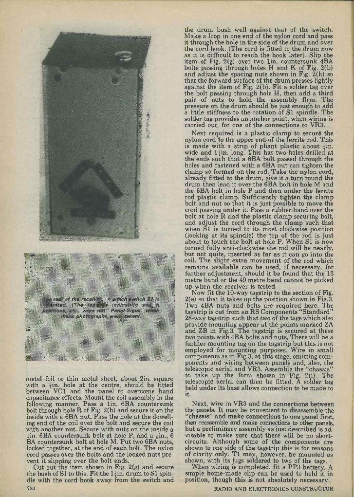
metal foil or thin metal sheet, about tin. square with a lin. hole at the centre, should be fitted between VC1 and the panel to overcome hand capacitance effects. Mount the coil assembly in the following manner. Pass a lin. 6BA countersunk bolt through hole R of Fig. 2(b) and secure it on the inside with a 6BA nut. Pass the hole at the dowell- ing end of the coil over the bolt and secure the coil with another nut. Secure with nuts on the inside a lin. 6BA countersunk bolt at hole P, and a 4in., 6 BA countersunk bolt at hole M. Put two 6BA nuts, locked together, at the end of each bolt. The nylon cord passes over the bolts and the locked nuts pre- vent it slipping over the bolt ends.
Cut out the item shown in Fig. 2(g) and secure the bush of Si to this. Fit the 11in. drum to S1 spin- dle with the cord hook away from the switch and 730
the drum bush well against that of the switch. Make a loop in one end of the nylon cord and pass it through the hole in the side of the drum and over the cord hook. (The cord is fitted to the drum now as it is difficult to reach the hook later). Slip the item of Fig. 2(g) over two lin. countersunk 4BA bolts passing through holes H and K of Fig. 2(b) and adjust the spacing nuts shown in Fig. 2(h) so that the forward surface of the drum presses lightly against the item of Fig. 2(b). Fit a solder tag over the bolt passing through hole H, then add a third pair of nuts to hold the assembly firm. The pressure on the drum should be just enough to add a little stiffness to the rotation of 51 spindle. The solder tag provides an anchor point, when wiring is carried out, for one of the connections to VR3.
Next required is a plastic clamp to secure the nylon cord to the upper end of the ferrite rod. This is made with a strip of pliant plastic about in. wide and 11 in. long. This has two holes drilled at the ends such that a 6BA bolt passed through the holes and fastened with a 6BA nut can tighten the clamp so formed on the rod. Take the nylon cord, already fitted to the drum, give it a turn round the drum then lead it over the 6BA bolt in hole M and the 6BA bolt in hole P and then under the ferrite rod plastic clamp. Sufficiently tighten the clamp bolt and nut so that it is just possible to move the cord passing under it. Pass a rubber band over the bolt at hole R and the plastic clamp securing bolt, and adjust the cord through the clamp such that when S1 is turned to its most clockwise position (looking at its spindle) the top of the rod is just about to touch the bolt at hole P. When S1 is now turned fully anti -clockwise the rod will be nearly, but not quite, inserted as far as it can go into the coil. The slight extra movement of the rod which remains available can be used, if necessary, for further adjustment, should it be found that the 13 metre band or the 49 metre band cannot be picked up when the receiver is tested.
Now fit the 10 -way tagstrip to the section of Fig. 2(e) so that it takes up the position shown in Fig.3. Two 4BA nuts and bolts are required here. The tagstrip is cut from an RS Components "Standard" 28 -way tagstrip such that two of the tags which also provide mounting appear at the points marked ZA and ZB in Fig.3. The tagstrip is secured at these two points with 4BA bolts and nuts. There will be a further mounting tag on the tagstrip but this is not employed for mounting purposes. Wire in small components as in Fig.3, at this stage, omitting com- ponents and wiring between panels and, also, the telescopic aerial and VR3. Assemble the "chassis" to take up the form shown in Fig. 2(i). The telescopic aerial can then be fitted. A solder tag held under its base allows connection to be made to it.
Next, wire in VR3 and the connections between the panels. It may be convenient to disassemble the "chassis" and make connections to one panel first, then reassemble and make connections to other panels, but a preliminary assembly as just described is ad- visable to make sure that there will be no short- circuits. Although some of the components are shown to one side of the tagstrip this is for reasons of clarity only. Tl may, however, be mounted as shown, with its lugs soldered to two of the tags.
When wiring is completed, fit a PP3 battery. A simple home-made clip can be used to hold it in position, though this is not absolutely necessary.
RADIO AND ELECTRONICS CONSTRUCTOR

TESTING Extend the aerial and adjust S1 so that the
ferrite rod is fully removed from the coil. Tune with VC1 and check that the 13 metre band is received when the vanes of this capacitor are nearly fully open. Greatest sensitivity is obtained when VR2 is set so that the receiver is just short of the oscillation point. Try all the switch positions and make sure that the 49 metre band is available when S1 is ad- justed for the ferrite rod to be fully in the coil. If necessary, adjust the ferrite rod clamp and nylon cord as previously described. Test for overlap between the ranges; this should exist although it will be extremely small. If overlap does not appear at any switch position, this will mean that at that particular setting the turns of the coil are too close, and they should be separated with a small screw- driver. When all is well, put a little clear varnish on the winding.
While testing, use the setting of VR1 which gives the necessary selectivity. Adjustment of VR1 will have some effect on the settings for VC1 and VR2. If it is found that, with certain settings of VC1 and VR1, oscillation cannot be obtained with VR2 at maximum, adjust VR3 to insert less resistance into circuit. Conversely, if oscillation at some settings cannot be controlled, adjust VR3 to insert more resistance. A setting of VR3 to suit all wavebands should be found. So far as is possible, arrange matters so that VR2 never has to be set near its minimum position to prevent oscillation.
Wavebands can be marked, and the control functions indicated, by legends taken from "Panel Signs" Set No. 3 (white) or Set No. 4 (black), available from the publishers of this journal. When completed, the receiver case can be enclosed by the
s.r.b.p. item which was cut out at the same time as that of Fig. 2(e).
EDITOR'S NOTE The 28 -way tagstrip from which the 10 -way strip
is cut is a "Standard" tagstrip listed by RS Com- ponents. In its 28 -way form it has a length of 267mm, whereupon the 10 -way strip has a length of approximately one-third of this. The tags are ver- tical to the mounting surface, with every third tag providing a mounting. Other tagstrips of similar dimensions could be employed. RS Components do not supply directly to individuals, and readers wishing to obtain the particular tagstrip used by the author and who do not have access to RS Com- ponents will need to obtain it through a retailer. The small radio and television shops, and their ser- vice engineers, may be helpful here. RS Com- ponents parts may also be obtained from Ace Mailtronix Limited, Tootal Street, Wakefield, West Yorkshire, WF1 5JR, subject to a minimum order of £2. A further section cut from the 28 -way strip is employed in the amplifier unit to be described next month.
A second TA10 telescopic aerial is employed in the v.h.f., medium and long wave tuner which con- cludes the "Doric" series and readers who an- ticipate making this may, if they wish, obtain the second aerial at the same time as the aerial employed for the short wave receiver which has been described here. The v.h.f., medium and long wave tuner also requires a further 4 or 4}in. length of orange grade ferrite rod, and this is again available from Amatronix.
(To be continued)
WORLD RADIO TV HANDBOOK
The 33rd edition of "World Radio TV Hand- book" has now become available. With 544 pages, the Handbook is crammed with informa- tion concerning radio and television transmissions throughout the world, and it lists the frequencies, schedules and other details of virtually every broadcasting station which is on the air. The edition takes in all the changes resulting from the Geneva Medium Wave Plan which came into effect in November 1978, and which applies to all countries outside the Americas.
The Handbook is of particular use to the short wave Dx listener who searches the bands for rewarding long distance reception. In addition to its frequency listings, the Handbook gives infor- mation on anticipated reception conditions in 1979, solar activity and similar subjects. Published by Billboard Publications Inc., the "World Radio TV Handbook" 33rd edition is priced at £8.50, and may be obtained from The Modern Book Company, 19-21 Praed Street (Dept. RC), London, W2 1NP. Price £9.15 in- clusive of postage and packing.
WILMSLOW AUDIO CATALOGUE
Currently available from Wilmslow Audio Ltd. is their latest 40 -page catalogue listing high fidelity speakers for all applications including domestic, group, public address and disco. The products of more than 30 manufacturers are presented in the catalogue, taking in such names as Celestion, Decca, E.M.I., Elac, Fane, Jordan, Watts, Motorola, Richard Allen, Tannoy, Wharfedale and Shackman. Products are il- lustrated by clear photographs and illustrations. Detailed product specifications are also provid- ed.
It should be noted that Wilmslow Audio Ltd. now offer the widest range of speaker drive units and speaker construction kits in Britain, and have supplied loudspeakers to the BBC, IBA, the Forces, Rolls Royce and many other organisations in addition to individual hi-fi enthusiasts. The catalogue can be obtained from Wilmslow Audio Ltd., Dept. REC, Swan Works, Bank Square, Wilmslow, Cheshire, SK9 11IF. A charge of 15p is made to cover postage.
AUGUST, 1979 731
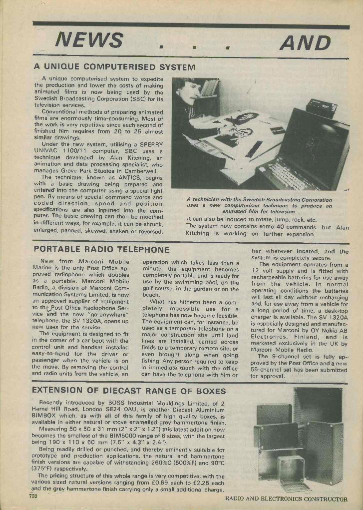
NEWS AND A UNIQUE COMPUTERISED SYSTEM
A unique computerised system to expedite the production and lower the costs of making animated films is now being used by the Swedish Broadcasting Corporation (SBC) for its television services.
Conventional methods of preparing animated films are enormously time-consuming. Most of the work is very repetitive since each second of finished film requires from 20 to 25 almost similar drawings.
Under the new system, utilising a SPERRY UNIVAC 1100/11 computer, SBC uses a
technique developed by Alan Kitching, an animation and data processing specialist, who manages Grove Park Studios in Camberwell.
The technique, known as ANTICS, begins with a basic drawing being prepared and entered into the computer using a special light pen. By means of special command words and coded direction, speed and position specifications are also inputted into the com- puter. The basic drawing can then be modified in different ways, for example, it can be shrunk, enlarged, panned, skewed, shaken or reversed.
A technician with the Swedish Broadcasting Corporation uses a new computerised technique to produce an
animated film for television. It can also be induced to rotate, jump, rock, etc. The system now contains some 40 commands but Alan Kitching is working on further expansion.
PORTABLE RADIO TELEPHONE New from Marconi Mobile
Marine is the only Post Office ap- proved radiophone which doubles as a portable. Marconi Mobile Radio, a division of Marconi Com- munication Systems Limited, is now an approved supplier of equipment to the Post Office Radiophone Ser- vice and the new "go -anywhere" telephone, the SV 1320A, opens up new uses for the service.
The equipment is designed to fit in the corner of a car boot with the control unit and handset installed easy -to-hand for the driver or passenger when the vehicle is on the move. By removing the control and radio units from the vehicle, an
operation which takes less than a minute, the equipment becomes completely portable and is ready for use by the swimming pool, on the golf course, in the garden or on the beach.
What has hitherto been a com- pletely impossible use for a telephone has now become feasible. The equipment can, for instance, be used as a temporary telephone on a major construction site until land lines are installed, carried across fields to a temporary remote site, or even brought along when going fishing. Any person required to keep in immediate touch with the office can have the telephone with him or
her wherever located, and the system is completely secure.
The equipment operates from a 12 volt supply and is fitted with rechargeable batteries for use away from the vehicle. In normal operating conditions the batteries will last all day without recharging and, for use away from a vehicle for a long period of time, a desk -top charger is available. The SV 1320A is especially designed and manufac- tured for Marconi by OY Nokia AB Electronics, Finland, and is marketed exclusively in the UK by Marconi Mobile Radio.
The 9 -channel set is fully ap- proved by the Post Office and a new 55 -channel set has been submitted for approval.
EXTENSION OF DIECAST RANGE OF BOXES Recently introduced by BOSS Industrial Mouldings Limited, of 2
Herne Hill Road, London SE24 OAU, is another Diecast Aluminium BIMBOX which, as with all of this family of high quality boxes, is available in either natural or stove enamelled grey hammertone finish.
Measuring 50 x 50 x 31 mm (2" x 2" x 1.2") this latest addition now becomes the smallest of the BIM5000 range of 6 sizes, with the largest being 190 x 110 x 60 mm (7.5" x 4.3" x 2.4").
Being readily drilled or punched, and thereby eminently suitable for prototype and production applications, the natural and hammertone finish versions are capable of withstanding 260%C (500%F) and 90°C (375°F) respectively.
The pricing structure of this whole range is very competitive, with the various sized natural versions ranging from £0.69 each to £2.25 each and the grey hammertone finish carrying only a small additional charge.
732 RADIO
vyy9ii:,<
AND ELECTRONICS CONSTRUCTOR

COMMENT THE SILENT LISTENERS
Much interest amongst radio amateurs was produced recently by the showing of a T.V. programme by the Norwich BBC T.V. station, made by one of their team, Paul Wright, G3SEM, which dealt with the work done during World War 2, by British radio amateurs enrolled into the Radio Security Service as V.I.s as they were called, which stood for "Voluntary Interceptors".
This story has just been released from its secrecy after 40 years of silence, as all the participants in it had to sign the Official Secrets Act. The film traced the origin of radio intelligence from world War 1 to the establishment of the V.I. service in W.W. 2 and outlines much of the work done by this service in listening to secret radio communications within the enemy's territory and to their agents elsewhere. Much of this listening was done in the V.I.'s own homes using their own radio equipment and few realised just what the messages they were copying were all about!
Amongst those involved with this service were Professor Trevor Roper, Colonel Maltby, Colonel Hornsby, 'Dud' Charman, (G6Cj), Louis Varney (G5RV), Pat Hawker (G3VA), Hugo Lawley (G6ZG) and our own Director, Dr. Arthur C. Gee, (G2UK) who appears quite prominently in the programme, some of which was filmed in his radio shack.
AVAILABILITY OF S-DECS
The manufacture and distribution of S-DeCs has now been taken over by Roden Products of 5 High March, Daventry. This photograph (which does not depict the assembly described in the Double Deccer article in this issue) demonstrates the neatness and simplicity which S-DeCs impart to
circuits. Back numbers containing numbers 1-8 of the
Double-Deccer series are all still available from the publishers of this magazine.
RADIO TRANSMITTERS AND MODULATION TECHNIQUES - I.E.E. CALL FOR PAPERS
The Institution of Electrical Engineers is seeking papers for a Conference on Radio Transmitters and Modulation Techniques" to be held at Savoy Place on 24-25 March 1980. Those wishing to have papers considered should submit a 50 -word synopsis to the IEE Conference Department by 3 September 1979.
Subjects to be covered at the Conference include the following: transmitters for communication (fix- ed and mobile), broadcasting, television, and navigational aid; improvements in transmitting valves; impact of power semiconductors on transmitter designs; new methods of modulation; exploitation of Doherty and pulse -width modula- tion and other methods for the purpose of higher ef- ficiency; transmitter control/ tuning, protection and safety; common antenna working (filters and other means); linearity control; frequency and signal generation; automatic monitoring and cor- rection; and spurious frequencies and noise radia- tion.
The Conference is being organised in association with the institution of Electronic and Radio Engineers and the Radio Society of Great Britain.
For further information please contact: Afflemarie Cunningham-Swendell, The Institution of Electrical Engineers, Savoy Place, London WC2R OBL.
WHO OWNS THE OLDEST RADIO?
Who owns the oldest radio that's still working? This was a competition organised by one of the BBC's local radio stations in Britain's East Midlands, Radio Leicester. And they got a bit of a surprise when the winning entry turned up.
How old do you think it was? 30 years, 40? No, more than that - there are many 40 -year -old radios still in use in Britain today. This particular radio makes 40 -year -old sets look like mere striplings - for the winning radio, still working, had seen service in the trenches during World War One (1914-1918) - one of the first valve radio sets ever made.
It still receives perfectly well the BBC's classical music channel and, of course, the local station that was running the competition, Radio Leicester.
It is mounted in a heavy wooden box with a leather carrying strap, and its works are completely exposed when the lid is opened. Inside the lid is a hand -drawn circuit diagram and hand-written in- structions, not only telling how to use it for receiv- ing, but also how to transmit in morse code. And the whole thing, with its batteries, is at least as heavy and big as a modern portable TV set.
BBC Radio Leicester presented the old set's proud owner, schoolmaster Gilbert King, with a prize - a new cassette recorder and radio com- bined.
AUGUST, 1979 733
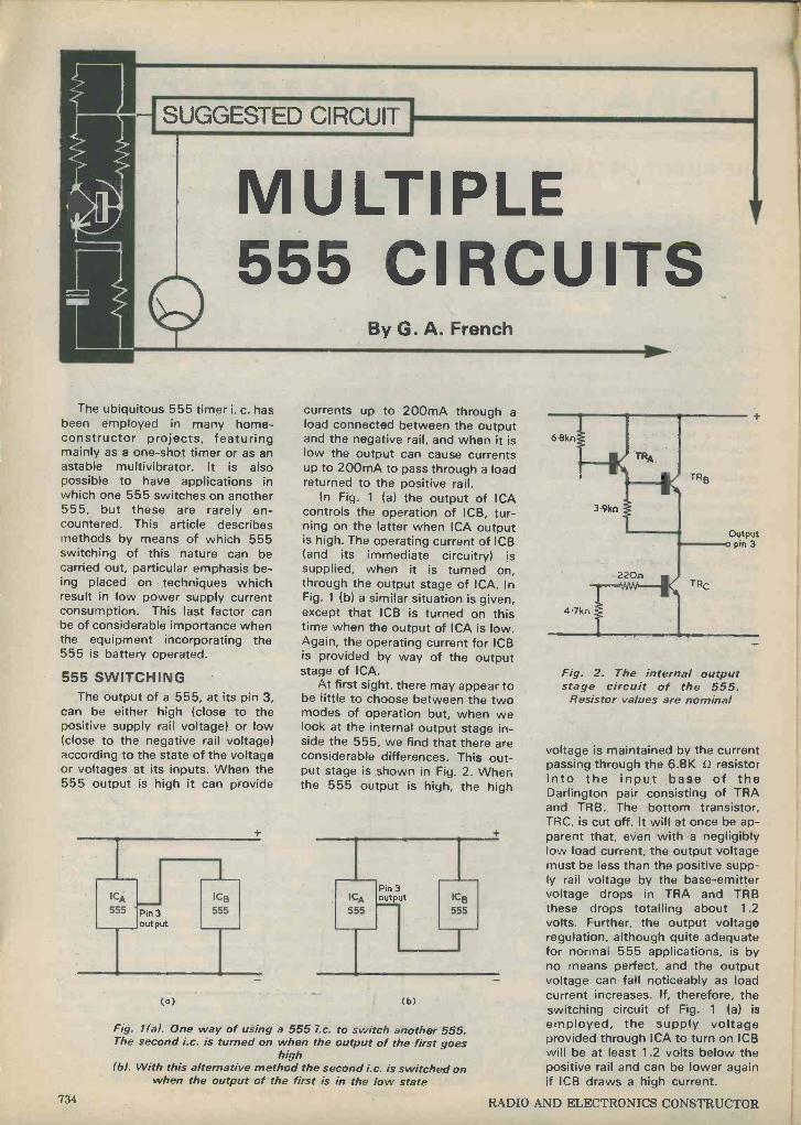
AS:
SUGGESTED CIRCUIT
MULTIPLE 555 CIRCUITS
By G. A. French
The ubiquitous 555 timer i. c. has been employed in many home - constructor projects, featuring mainly as a one-shot timer or as an astable multivibrator. It is also possible to have applications in which one 555 switches on another 555, but these are rarely en- countered. This article describes methods by means of which 555 switching of this nature can be carried out, particular emphasis be- ing placed on techniques which result in low power supply current consumption. This last factor can be of considerable importance when the equipment incorporating the 555 is battery operated.
555 SWITCHING The output of a 555, at its pin 3,
can be either high (close to the positive supply rail voltage) or low (close to the negative rail voltage) according to the state of the voltage or voltages at its inputs. When the 555 output is high it can provide
(o)
currents up to 200mA through a load connected between the output and the negative rail, and when it is low the output can cause currents up to 200mA to pass through a load returned to the positive rail.
In Fig. 1 (a) the output of ICA controls the operation of ICB, tur- ning on the latter when ICA output is high. The operating current of ICB (and its immediate circuitry) is supplied, when it is turned on, through the output stage of ICA. In Fig. 1 (b) a similar situation is given, except that ICB is turned on this time when the output of ICA is low. Again, the operating current for ICB is provided by way of the output stage of ICA.
At first sight, there may appear to be little to choose between the two modes of operation but, when we look at the internal output stage in- side the 555, we find that there are considerable differences. This out- put stage is shown in Fig. 2. When the 555 output is high, the high
ICA
555
Pin 3 output ICB
555
(b)
Fig. 1(a). One way of using a 555 i.c. to switch another 555. The second i.c. is turned on when the output of the first goes
high (b). With this alternative method the second i.c. is switched on
when the output of the first is in the low state
TRB
TRC
1
Output o pin 3
Fig. 2. The internal output stage circuit of the 555.
Resistor values are nominal
voltage is maintained by the current passing through the 6.8K S2 resistor into the input base of the Darlington pair consisting of TRA and TRB. The bottom transistor, TRC, is cut off. It will at once be ap- parent that, even with a negligibly low load current, the output voltage must be less than the positive supp- ly rail voltage by the base -emitter voltage drops in TRA and TRB these drops totalling about 1.2 volts. Further, the output voltage regulation, although quite adequate for normal 555 applications, is by no means perfect, and the output voltage can fall noticeably as load current increases. If, therefore, the switching circuit of Fig. 1 (a) is
employed, the supply voltage provided through ICA to turn on ICB will be at least 1.2 volts below the positive rail and can be lower again if ICB draws a high current.
734 RADIO AND ELECTRONICS CONSTRUCTOR
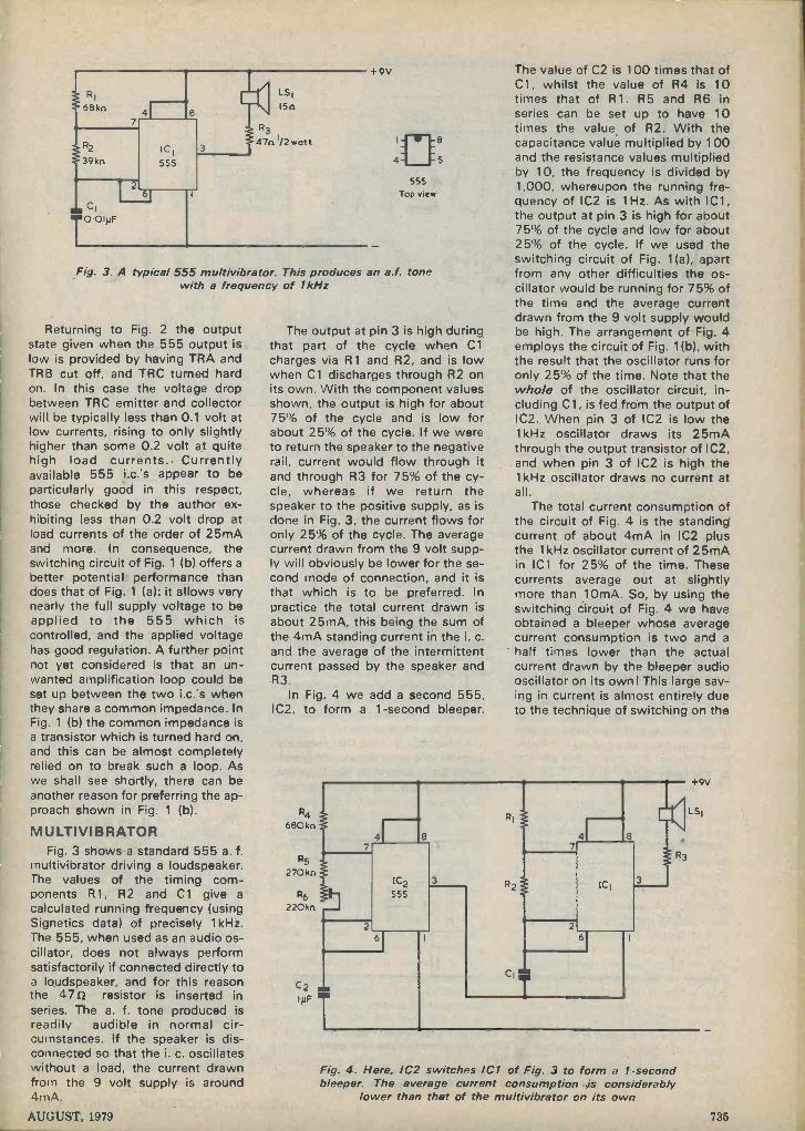
RI
68kn
R2
39kn
100(IJF
ICI 555
6
I -SI ISO
R3
470I/2watt
+9V
555 Top view
Fig. 3. A typical 555 multivibrator. This produces an a.f. tone with a frequency of 1 kHz
Returning to Fig. 2 the output state given when the 555 output is low is provided by having TRA and TRB cut off, and TRC turned hard on. In this case the voltage drop between TRC emitter and collector will be typically less than 0.1 volt at low currents, rising to only slightly higher than some 0.2 volt at quite high load currents.. Currently available 555 i.c.'s appear to be particularly good in this respect, those checked by the author ex- hibiting less than 0.2 volt drop at load currents of the order of 25mA and more. In consequence, the switching circuit of Fig. 1 (b) offers a
better potential performance than does that of Fig. 1 (a): it allows very nearly the full supply voltage to be applied to the 555 which is controlled, and the applied voltage has good regulation. A further point not yet considered is that an un- wanted amplification loop could be set up between the two i.c.'s when they share a common impedance. In Fig. 1 (b) the common impedance is a transistor which is turned hard on, and this can be almost completely relied on to break such a loop. As we shall see shortly, there can be another reason for preferring the ap- proach shown in Fig. 1 (b).
MULTIVIBRATOR Fig. 3 shows a standard 555 a. f.
multivibrator driving a loudspeaker. The values of the timing com- ponents R1, R2 and Cl give a
calculated running frequency (using Signetics data) of precisely 1 kHz. The 555, when used as an audio os- cillator, does not always perform satisfactorily if connected directly to a loudspeaker, and for this reason the 47s2 resistor is inserted in series. The a. f. tone produced is readily audible in normal cir- cumstances. If the speaker is dis- connected so that the i. c. oscillates without a load, the current drawn from the 9 volt supply is around 4mA.
5
The output at pin 3 is high during that part of the cycle when Cl charges via R1 and R2, and is low when Cl discharges through R2 on its own. With the component values shown, the output is high for about 75% of the cycle and is low for about 25% of the cycle. If we were to return the speaker to the negative rail, current would flow through it and through R3 for 75% of the cy- cle, whereas if we return the speaker to the positive supply, as is done in Fig. 3, the current flows for only 25% of the cycle. The average current drawn from the 9 volt supp- ly will obviously be lower for the se- cond mode of connection, and it is that which is to be preferred. In practice the total current drawn is about 25mA, this being the sum of the 4mA standing current in the i. c. and the average of the intermittent current passed by the speaker and R3.
In Fig. 4 we add a second 555, IC2, to form a 1 -second bleeper.
The value of C2 is 100 times that of C1, whilst the value of R4 is 10 times that of R1. R5 and R6 in series can be set up to have 10 times the value of R2. With the capacitance value multiplied by 100 and the resistance values multiplied by 10, the frequency is divided by 1,000, whereupon the running fre- quency of IC2 is 1Hz. As with IC1, the output at pin 3 is high for about 75% of the cycle and low for about 25% of the cycle. If we used the switching circuit of Fig. 1(a), apart from any other difficulties the os- cillator would be running for 75% of the time and the average current drawn from the 9 volt supply would be high. The arrangement of Fig. 4 employs the circuit of Fig. 1(b), with the result that the oscillator runs for only 25% of the time. Note that the whole of the oscillator circuit, in- cluding Cl, is fed from the output of IC2. When pin 3 of IC2 is low the 1 kHz oscillator draws its 25mA through the output transistor of IC2, and when pin 3 of IC2 is high the 1 kHz oscillator draws no current at all.
The total current consumption of the circuit of Fig. 4 is the standing current of about 4mA in IC2 plus the 1 kHz oscillator current of 25mA in IC1 for 25% of the time. These currents average out at slightly more than IOmA. So, by using the switching circuit of Fig. 4 we have obtained a bleeper whose average current consumption is two and a half times lower than the actual current drawn by the bleeper audio oscillator on its own! This large sav- ing in current is almost entirely due to the technique of switching on the
+9V
R4 / LS1
680kn
R5 R3
270kn IC2 ICI
R6 j 555
220kn J
C2 m, INFT
Fig. 4. Here, IC2 switches IC1 of Fig. 3 to form a 1 -second bleeper. The average current consumption is considerably
lower than that of the multivibrator on its own
AUGUST, 1979 735

R8
IMn
R9
12 Mn
C4 an IOONF
R7 1.2Mn
RIO IMn
2
IC3
555
an C3
T47NF
3
R11
150n
IC2
R12 >47kn =C2
TR' BC 107
6
+9V
o C5 IOONF
BC 107 Lead -outs
C
Fig. 5. Yet another 555, 1C3, is added to the circuit of Fig. 4. The bleeper is turned off for 5 seconds and is then turned on for 10 seconds, giving a total cycle length of 15 seconds
oscillator from the output of IC2 when that output is in the low state.
In practice, the tolerances in the timing components of IC2 are taken up by adjusting R6 so that the bleeper runs as near to 1 Hz as can be arranged. The bleeper can then function as a photographer's metronome or for timing other operations which are carried out in fixed numbers of seconds.
A THIRD 555
The metronome performance would be enhanced if we were to add a further 555 which caused the bleeper to sound for 10 seconds, to be silent for 5 seconds, to sound again for another 10 seconds, and so on. The complete cycle of 15 seconds, or quarter of a minute, would be of particular assistance for timing longer processes.
The requisite circuit is shown in Fig. 5. Since we are switching the bleeper on for a longer period than that when it is switched off, the bleeper has to be turned on when the pin 3 output of the third 555 is high rather than when it is low. The difficulties mentioned earlier will be present if we attempt to supply the bleeper directly from the pin 3 out- p.it when it is high, and there is
another problem in the present in- stance which is due to the switched pulses already present on the positive supply rail. These make it necessary to decouple the positive supply to the third 555 to prevent false triggering. If the bleeper were to draw current from its pin 3 that current would also flow through the decoupling resistor.
In Fig. 5 IC3 turns the bleeper on and off by way of the inverting tran- sistor TR 1 . When IC3 output is low, TR 1 is cut off and the bleeper sec- tion draws no current. TR 1 is turned hard on when pin 3 goes high and it then passes all the current required by the bleeper. The decoupling com- ponents for IC3 are R11 and C4. Although not entirely essential, a bypass capacitor, C5, is also added across the 9 volt supply.
The circuit is set up by first ad- justing R10 for a 5 second silent period from the bleeper, after which R8 is set up so that the bleeper produces 10 tone pulses during the period when it is turned on. It may be found necessary to slightly alter the values of R9 and R7. If it is found that the 5 second period is outside the range of R10 the value of R9 Inay be slightly increased or decreased as necessary. Similarly, the value of R7 may be slightly in-
creased or decreased if the requisite series of 10 bleeps is outside the range of R8. With the prototype, the final settings in R8 and R10 were fairly close to the centres of their slider travel.
The total current from the 9 volt supply is now 4mA in IC3 when the bleeper is silent plus the current drawn by the bleeper and that flow- ing through R12 when the bleeper is turned on. The average current is therefore about 12mA, a slight in- crease on the average current of the continually running bleeper on its own.
Apart from R3, all the resistors in the circuits shown are ; watt, with a tolerance of 5% below 1M 0. and 10% above 1M O . Both C2 and C3 should be polyester capacitors. 4.711F polyester capacitors are available from Greenweld, 443 Millbrook Road, Southampton. The three pre-set potentiometers can be 0.1 watt skeleton types.
A final point is that, after switching on the circuit of Fig. 5, the bleeper will produce more than 10 tone pulses before the circuit settles into its cycles of 5 seconds silence followed by 10 bleeps. The extra bleeps immediately after switch -on are given as C3 charges initially from its fully discharged state.
736 RADIO AND ELECTRONICS CONSTRUCTOR
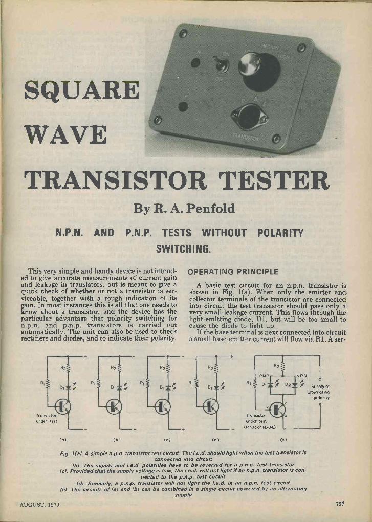
SQUARE
WAVE
TRANSISTOR TESTER By R. A. Penfold
N.P.N. AND P.N.P. TESTS WITHOUT POLARITY
SWITCHING.
This very simple and handy device is not intend- ed to give accurate measurements of current gain and leakage in transistors, but is meant to give a quick check of whether or not a transistor is ser- viceable, together with a rough indication of its gain. In most instances this is all that one needs to know about a transistor, and the device has the particular advantage that polarity switching for n.p.n. and p.n.p. transistors is carried out automatically. The unit can also be used to check rectifiers and diodes, and to indicate their polarity.
RI
Transistor under test
(a)
RI
(b) (c)
OPERATING PRINCIPLE
A basic test circuit for an n.p.n. transistor is shown in Fig. 1(a). When only the emitter and collector terminals of the transistor are connected into circuit the test transistor should pass only a very small leakage current. This flows through the light -emitting diode, D1, but will be too small to cause the diode to light up.
If the base terminal is next connected into circuit a small base -emitter current will flow via R1. A ser-
(d)
Transistor under test
(P.N.P or N.P.N.)
N.P.N
Supply of alternating
polarity
(e)
Fig. 1(a). A simple n.p.n. transistor test circuit. The l.e.d. should light when the test transistor is connected into circuit
(b). The supply and l.e.d. polarities have to be reversed for a p.n.p. test transistor (c). Provided that the supply voltage is low, the l.e.d. will not light if an n.p.n. transistor is con-
nected to the p.n.p. test circuit (d). Similarly, a p.n.p. transistor will not light the l.e.d. in an n.p.n. test circuit
(e). The circuits of (a) and (b) can be combined in a single circuit powered by an alternating supply
AUGUST, 1979 737
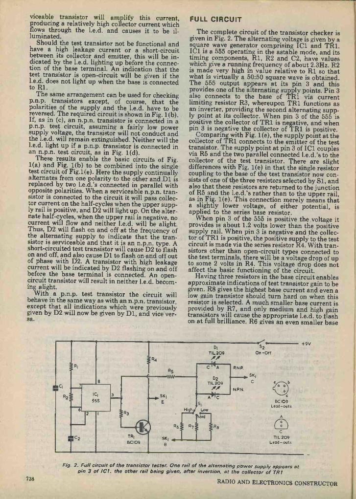
viceable transistor will amplify this current, producing a relatively high collector current which flows through the l.e.d. and causes it to be il- luminated.
Should the test transistor not be functional and have a high leakage current or a short-circuit between its collector and emitter, this will be in- dicated by the l.e.d. lighting up before the connec- tion of the base terminal. An indication that the test transistor is open -circuit will be given if the l.e.d. does not light up when the base is connected to R1.
The same arrangement can be used for checking p.n.p. transistors except, of course, that the polarities of the supply and the l.e.d. have to be reversed. The required circuit is shown in Fig. 1(b). If, as in (c), an n.p.n. transistor is connected in a p.n.p. test circuit, assuming a fairly low power supply voltage, the transistor will not conduct and the l.e.d. will remain extinguished. Neither will the I.e.d. light up if a p.n.p. transistor is connected in an n.p.n. test circuit, as in Fig. 1(d).
These results enable the basic circuits of Fig. 1(a) and Fig. 1(b) to be combined into the single test circuit of Fig.1(e). Here the supply continually alternates from one polarity to the other and D1 is replaced by two l.e.d.'s connected in parallel with opposite polarities. When a serviceable n.p.n. tran- sistor is connected to the circuit it will pass collec- tor current on the half -cycles when the upper supp- ly rail is positive, and D2 will light up. On the alter- nate half -cycles, when the upper rail is negative, no current will flow and neither l.e.d. will be alight. Thus, D2 will flash on and off at the frequency of the alternating supply to indicate that the tran- sistor is serviceable and that it is an n.p.n. type. A short-circuited test transistor will cause D2 to flash on and off, and also cause D1 to flash on and off out of phase with D2. A transistor with high leakage current will be indicated by D2 flashing on and off before the base terminal is connected. An open - circuit transistor will result in neither l.e.d. becom- ing alight.
With a p.n.p. test transistor the circuit will behave in the same way as with an n.p.n. transistor, except that all indications which were previously given by D2 will now be given by D1, and vice ver- sa.
FULL CIRCUIT
The complete circuit of the transistor checker is given in Fig. 2. The alternating voltage is given by a square wave generator comprising IC1 and TRI. IC1 is a 555 operating in the astable mode, and its timing components, R1, R2 and C2, have values which give a running frequency of about 2.3Hz. R2 is made very high in value relative to R1 so that what is virtually a 50:50 square wave is obtained. The 555 output appears at its pin 3 and this provides one of the alternating supply points. Pin 3 also connects to the base of TR1 via current limiting resistor R3, whereupon TR1 functions as an inverter, providing the second alternating supp- ly point at its collector. When pin 3 of the 555 is positive the collector of TR1 is negative, and when pin 3 is negative the collector of TRl is positive.
Comparing with Fig. 1(e), the supply point at the collector of TR1 connects to the emitter of the test transistor. The supply point at pin 3 of IC1 couples via R5 and the two parallel connected 1.e.d.'s to the collector of the test transistor. There are slight differences with Fig. 1(e) in that the single resistor coupling to the base of the test transistor now con- sists of one of the three resistors selected by Si, and also that these resistors are returned to the junction of R5 and the l.e.d.'s rather than to the upper rail, as in Fig. 1(e). This connection merely means that a slightly lower voltage, of either potential, is applied to the series base resistor.
When pin 3 of the 555 is positive the voltage it provides is about 1.2 volts lower than the positive supply rail. When pin 3 is negative and the collec- tor of TR1 is positive, the positive supply to the test circuit is made via the series resistor R4. With tran- sistors other than open -circuit types connected to the test terminals, there will be a voltage drop of up to some 2 volts in R4. This voltage drop does not affect the basic functioning of the circuit.
Having three resistors in the base circuit enables approximate indications of test transistor gain to be given. R8 gives the highest base current and even a low gain transistor should turn hard on when this resistor is selected. A much smaller base current is provided by R7, and only medium and high gain transistors will cause the appropriate l.e.d. to flash on at full brilliance. R6 gives an even smaller base
1c1R2
eRI
ICI
555
NM C2
2
TRI
BC 109
5K1
E
5K1
B
01
TIL 209 rr c I4A
02 TI L 209 r A>IC
SI
High Low
?Mcd
52
On -Oft
P.N.P.
SKI
C
N.P.N.
BC 109 Lead -outs
Tit_ 209 Lead - outs
+9V
Fig. 2. Full circuit of the transistor tester. One rail of the alternating power supply appears at pin 3 of IC1, the other rail being given, after inversion, at the collector of TR1
738 RADIO AND ELECTRONICS CONSTRUCTOR

Battery clip
42mm
/ Mounting holes
Fig. 3. Preparation of the printed circuit board and the point-to-point wiring in the transistor tester
current, and only high gain transistors will produce full brilliance from the 1.e.d. when this resistor is switched in. In consequence, it is possible to obtain a reasonable idea of the test transistor gain by ad- justing Si.
S2 is the on -off switch and Cl is a supply decoupling capacitor. The current consumption from the 9 volt battery is of the order of 16 to 18mA. The prototype unit employs a PP3 battery, and this will have a reasonable life span for the transistor testing likely to be carried out by the average user. If continual and extended use of the tester is envisaged, it would be preferable to employ a larger battery such as a PP7 or even a PP9.
CONSTRUCTION Any small plastic case capable of taking the
components and the battery may be used, and the prototype was housed in a plastic case with a slop- ing panel having approximate outside dimensions of 107 by 75 by 43mm. This is available from Home Radio (Components) Ltd. The front panel layout used by the author can be seen in the photographs. The n.p.n. indicator, D2, is at the up- per left, with the p.n.p. indicator, D1, below it. Si is at upper right with the test transistor socket below it, and S2 appears between D2 and Si. The l.e.d.'s are held in place by panel mounting bushes, and connections are made direct to their lead -outs.
The test transistor socket is a 3 -way DIN socket, and many small transistors will plug directly into this. To cater for those which will not it is necessary to make up a test lead set. This simply consists of a 3 -way DIN plug to which are connected three flexible leads of different colours terminated in miniature crocodile clips.
Most of the small components are assembled on a printed circuit board measuring 54 by 42mm., and this is reproduced full size in Fig. 3. R6 to R8 are mounted on the tags of Sl. This is a 3 -way 4 - pole rotary switch with with only one pole used, and it is advisable to confirm with a continuity tester the three outer tags which correspond to the inner tag before wiring to this component. With some switches the relative positioning of the tags may vary from that shown in Fig. 3. The mounting holes in the printed circuit are for 6BA or M3 bolts and, when all the wiring is finally completed, the printed board is mounted on the rear panel of the case, behind Si and the DIN test socket, by short bolts and nuts of the appropriate size. Spacing washers are needed on the bolts between the inside surface of the case and the printed board underside to prevent strain on the board when the nuts and bolts are tightened up. There is plenty of space for the PP3 battery in the remaining space on the rear panel and this can be held in place with a home- made metal bracket. Alternatively, the battery can be secured by a piece of Bostik Blue Tack.
AUGUST, 1979 739

The printed board and the battery are position- ed at the rear of the case. The remaining com-
ponents are mounted on the front panel
USING THE UNIT After completion the unit should be switched on
with no test transistor connected. If either of the l.e.d.'s flashes even dimly there is a wiring error which has to be corrected.
When testing transistors, only the emitter and collector of the test transistor should be initially connected to the unit, whereupon neither 1.e.d.'s should light up. Germanium transistors have higher leakage currents than silicon types and it is possible that a functional germanium device may cause one of the l.e.d.'s to light up rather dimly. However, the author tested a number of ger- manium transistors including small power output types, and none of them exhibited a sufficiently high leakage current to cause a visible glow in either l.e.d. When the base of the test transistor is
The printed circuit board is quite a simple assembly, with the components arranged as
shown here
COMPONENTS
Resistors (All ; watt 5% unless otherwise stated)
R1 1.2ku R5 lksz R2 6.8Mc 10% R6 1Mc R3 15kß R7 100k 0 R4 560 o R8 10k o
Capacitors Cl 0.1íF type C280 C2 0.047pF type C280
Semiconductors IC1 555 TR1 Bí,109 D1 TIL209 with panel -mounting bush D2 TIL209 with panel -mounting bush
Switches S1 1 -pole 3 -way miniature rotary (see text) S2 s.p.s.t. subminiature toggle
Socket SK1 3 -way DIN socket
Miscellaneous Plastic case (see text) 9 -volt battery type PP3 (see text) Battery connector Control knob 3 -way DIN plug 3 miniature crocodile clips Materials for printed board Nuts, bolts, wire, etc.
connected to the checker, either D1 or D2, as ap- propriate to the transistor type, should flash on and off at a rate of the order of 2 times a second.
If both l.e.d.'s flash on and off when the emitter and collector terminals are connected to the checker the test transistor is short-circuited and is unusable. Should neither l.e.d. flash when all three terminals are connected then the transistor is open - circuit and is similarly unusable.
For these tests, S1 is always set to the position which brings R8 into circuit. S1 is brought into use when a medium or high gain transistor is suspected of having inadequate gain or when it is desired to select transistors in approximate terms of gain. After confirming the general serviceability of the transistor with R8 selected, S1 then switches in R7 and R6. With R7 in circuit the test transistor needs to have a gain of about 50 times or more in order to bring the appropriate l.e.d. up to about full brightness. A current gain of at least a few hundred times is required for the same indication with R6 selected. On the prototype unit, the corresponding positions of S1 are indicated on the front panel by the legends "LOW", "MEDIUM" and "HIGH". These legends are cut out from "Panel -Signs" Set No. 3, available from the publishers of this journal.
Rectifiers and diodes may also be checked. The cathode (usually marked by a coloured band around the body of the component) is connected to the emitter test point and the anode to the collector test point. This should result in D2 (n.p.n.) flashing on and off. If the connection causes D1 to flash then the cathode has been connected to the collec- tor instead of the emitter test point. If neither 1.e.d. flashes the rectifier or diode is open -circuit, and if both 1.e.d.'s flash the device is short-circuited. zi
740 RADIO AND ELECTRONICS CONSTRUCTOR
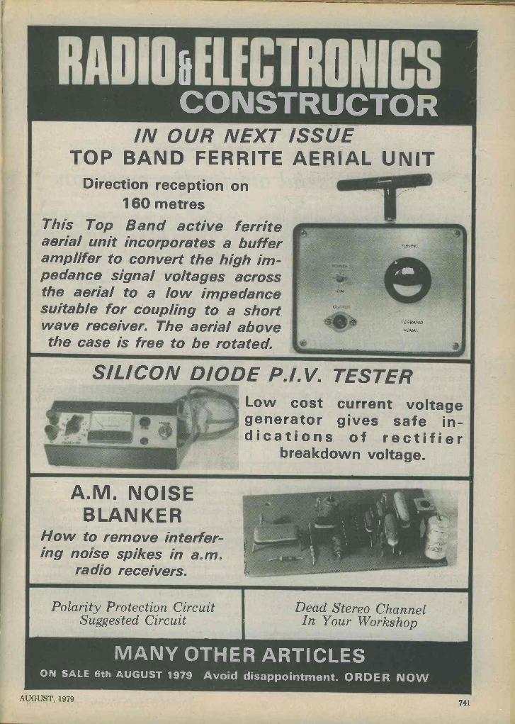
A ELECTRONICS CONSTRUCTOR
IN OUR NEXT ISSUE TOP BAND FERRITE AERIAL UNIT
Direction reception on 160 metres
This Top Band active ferrite aerial unit incorporates a buffer amplifer to convert the high im- pedance signal voltages across the aerial to a low impedance suitable for coupling to a short wave receiver. The aerial above the case is free to be rotated.
SILICON DIODE P.I.V. TESTER Low cost current voltage generator gives safe in- dications of rectifier
breakdown voltage.
A.M. NOISE BLANKER
How to remove interfer- ing noise spikes in a.m.
radio receivers.
Polarity Protection Circuit Suggested Circuit
Dead Stereo Channel In Your Workshop
MANY OTHER ARTICLES ON SALE 6th AUGUST 1979 Avoid disappointment. ORDER NOW
AUGUST, 1979 741

VISUAL METRONOME
WITH DOWNBEAT by Paul M. Jessop
A really useful aid for the musician The mechanical metronome was invented by
Maezel around 1800 and has proved remarkably durable as an aid to musicians. Its basic principles have not been altered but for a few minor additions since its conception. One of these additions, found on some modern models, is a counter which rings a small bell on the first beat of each bar. This is known as the "downbeat" since it is the beat on which a conductor would bring his baton vertically downwards. The counting is done mechanically and the counting ratio, i.e. the number of beats per ring of the bell, can be altered by means of a knob to give varying time signatures.
The metronome is used largely by musicians when learning to play a piece so that they can ac- curately gauge the pace of the piece when they come to perform it. However, it would be useful if conductors could also make use of such an instru- ment when conducting to ensure an even pace throughout. It is not suggested that all music re- quires this, but some specifically calls for it and some would benefit from it. For this purpose the
CI
u
"click, click" of the mechanical metronome is clear- ly unacceptable, and so it was decided to use an l.e.d. to indicate the beats. It was also decided that: the downbeat facility was useful and, initially, the downbeat was to have been indicated by making the l.e.d. flash more brightly. This approach was abandoned, however, because the display was not nearly clear enough. The method decided upon was to have two l.e.d's, one flashing on every beat and the other flashing only on the downbeat. The overall effect is similar to the initial method but is much more readily noticeable.
'THE CIRCUIT The circuit of the metronome is shown in the ac-
companying diagram, and it operates in the follow- ing manner. The NAND gates G1 and G2 form a free running astable multivibrator whose frequen- cy is determined by VR1, R1 and Cl. R1 is includ- ed to limit the upper frequency available, which would otherwise be unnecessarily high. The output
Pin 14
12 RI
WAA---W/Vti VRI 13
G1 G2
G4 DI / D2
G3
R2
10 14
16
13
ICI
CD 4011
Pin 7
t
I 1a I- T' 16 CD4OI1
Top view CD4022 Top view
7 8 9
IC 2
CD 4022
Clock
Clock enable
O
2
3
65 6 Reset 7
4=4 SI 54 f 8 15
R4 f
s2
-t6to12V On -Off
C2
The circuit of the metronome. The downbeat is indicated by DI flashing in unison with 02, the number of beats in each bar being selected by S 1
742 RADIO AND ELECTRONICS CONSTRUCTOR

COMPONENTS
Resistors (All fixed values ; watt 10%) R1 150kß R2 390 e R3 39011 R4 12k11 VR1 2.2M c potentiometer, linear
Capacitors Cl 0.47,uF type C280 C2 10p.F electrolytic, 16 V. Wkg.
Semiconductors IC1. CD4011 IC2 CD4022 D1 light -emitting diode, red D2 light -emitting diode, red
Switch S1 1 -pole 8 -way rotary S2 s.p.s.t., toggle or slide
Miscellaneous Circuit board Battery, 6V, 9V or 12V 2 knobs Case
of G2 is fed to both inputs of G3 which acts as an inverter giving an output signal with steeply rising edges. This output feeds an l.e.d., D2, through a current limiting resistor. The l.e.d. is taken to the positive supply line so that it is on when the output of G3 is low, and therefore when the output of G2 is high. The output of G3 also feeds pin 14 of IC2. IC2 is a divide -by -eight counter with eight decoded out- puts and pin 14 is the clock input. To make the counter operate it is necessary to take the clock enable input (pin 13) low, and in this application the enable pin is wired permanently to the negative supply line.
On each rising edge of the clock input the counter advances by one and the corresponding output goes high. The reset pin (pin 15) is switchable between any of these outputs and this has the effect of alter- ing the divide ratio of the counter. Consider what happens if the reset pin is connected to the "4" out- put. The chip counts from zero to three in the nor- mal manner and then, on the next rising edge of the clock input, the "4" output goes high. This is of course connected to the reset input so the latter is also taken high, setting the counter to zero. Thus the counter spends practically no time with the "4" output high. In all, four pulses on the clock input cause the "0" output to go high once; this means that the counter is operating in a divide -by -four mode.
Now, the "0" output is fed to one of the inputs to G4, whose other input takes the original clock signal from the multivibrator. The output of G4 drives the l.e.d. which indicates the downbeat. Because G4 is a NAND gate, it is again necessary to drive the l.e.d. between the output and the positive supply line, giving inverted operation.
Since the "0" output goes high once per complete cycle, the effect is that D2 flashes at a regular rate, and on every, say, fourth flash D1 flashes with D2,
indicating the downbeat. The fact that when D1 flashes, D2 flashes at exactly the same time gives great visual impact. Naturally, setting S1 to alter- native positions controls the number of flashes in D2 for every downbeat flash in Dl. With S1 at position "8" the counter itself divides by this number.
CONSTRUCTION Layout is not critical and the metronome can be
built in any way favoured by the constructor. The author's prototype was assembled using plain 0.1 in. perforated board and i.c. sockets, and a wiring pencil dispensing solder -through enamelled wire. Since the integrated circuits are CMOS devices, the sockets enable the wiring to be completed and checked before the i.c.'s are removed from their shorting foam or foil and inserted in their holders.
Switch S1 can be a single pole 12 -way rotary type with adjustable end stop set for 8 -way opera- tion. The supply voltage may have any value between 6 and 12 volts.
The housing is very much a matter of personal taste, although if the unit is to be used for concerts the traditional pyramidal housing might best be neglected in favour of a more unobtrusive box which can rest on the conductor's podium. Both the tempo control, VR1, and the beats -per -bar switch must be clearly calibrated and easily accessible. The calibration of VR1 is an easy matter, con- sisting of counting the number of flashes of the faster l.e.d. in a minute at different settings of the potentiometer. This value is the number found on a musical score.
It would be unreasonable to say that a box such as this will ever replace the conductor, but it may help to make his task at least a little less deman- ding. s
BACK NUMBERS For the benefit of new readers we would draw attention to our back number service.
We retain past issues for a period of two years and we can, occasionally, supply copies more than two years
old. The cost is 63p, inclusive of postage and packing.
Before undertaking any constructional project described in a back issue, it must be borne in mind that com-
ponents readily available at the time of publication may no longer be so.
-AUGUST, 1979 743
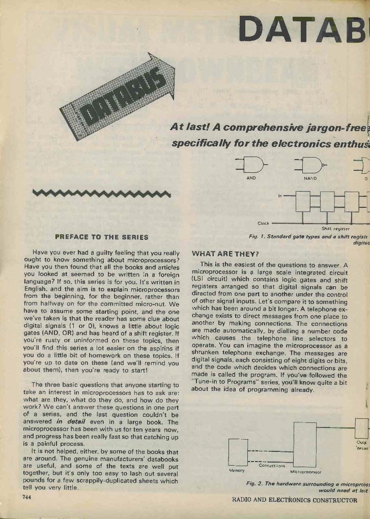
DATABi
At last! A comprehensive jargon-fi'eep specifically for the electronics enthusi
PREFACE TO THE SERIES
Have you ever had a guilty feeling that you really ought to know something about microprocessors? Have you then found that all the books and articles you looked at seemed to be written ;n a foreign language? If so, this series is for you. It's written in English, and the aim is to explain microprocessors from the beginning, for the beginner, rather than from halfway on for the committed micro -nut. We have to assume some starting point, and the one we've taken is that the reader has some clue about digital signals (1 or 0), knows a little about logic gates (AND, OR) and has heard of a shift register. If you're rusty or uninformed on these topics, then you'll find this series a lot easier on the aspirins if you do a little bit of homework on these topics. If you're up to date on these (and we'll remind you about them), then you're ready to start!
The three basic questions that anyone starting to take an interest in microprocessors has to ask are: what are they, what do they do, and how do they work? We can't answer these questions in one part of a series, and the last question couldn't be answered in detail even in a large book. The microprocessor has been with us for ten years now, and progress has been really fast so that catching up is a painful process.
It is not helped, either, by some of the books that are around. The genuine manufacturers' databooks are useful, and some of the texts are well put together, but it's only too easy to lash out several pounds for a few scrappily -duplicated sheets which tell you very little. 744
AND NAND 0:
In
Clock ITT Shift register
Fig. 1. Standard gate types and a shift registe. digitac
WHAT ARE THEY? This is the easiest of the questions to answer. A
microprocessor is a large scale integrated circuit (LSI circuit) which contains logic gates and shift registers arranged so that digital signals can be directed from one part to another under the control of other signal inputs. Let's compare it to something which has been around a bit longer. A telephone ex- change exists to direct messages from one place to another by making connections. The connections are made automatically, by dialling a number code which causes the telephone line selectors to operate. You can imagine the microprocessor as a shrunken telephone exchange. The messages are digital signals, each consisting of eight digits or bits, and the code which decides which connections are made is called the program. If you've followed the "Tune -in to Programs" series, you'll know quite a bit about the idea of programming already.
Memory Connections
Microprocessor
Outpt
.decctr
Fig. 2. The hardware surrounding a micropronss would need at leert
RADIO AND ELECTRONICS CONSTRUCTOR
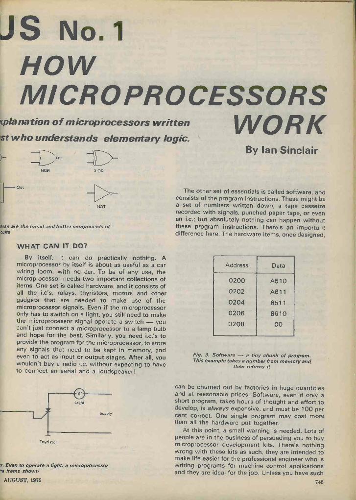
JS No.1 HOW MICRO PR CESSORS
i;planation of microprocessors written WO R K st who understands elementary logic.
NOR X OR
Out
NOT
lese are the bread and butter components of 'cuits
WHAT CAN IT DOT
By itself, it can do practically nothing. A microprocessor by itself is about as useful as a car wiring loom, with no car. To be of any use, the microprocessor needs two important collections of items. One set is called hardware, and it consists of all the i.c's, relays, thyristors, motors and other gadgets that are needed to make use of the microprocessor signals. Even if the microprocessor only has to switch on a light, you still need to make the microprocessor signal operate a switch - you can't just connect a microprocessor to a lamp bulb and hope for the best. Similarly, you need i.c.'s to provide the program for the microprocessor, to store any signals that need to be kept in memory, and even to act as input or output stages. After all, you wouldn't buy a radio i.c. without expecting to have to connect an aerial and a loudspeaker!
Thyristor
n. Even to operate a light, a microprocessor he items shown
By Ian Sinclair
The other set of essentials is called software, and consists of the program instructions. These might be a set of numbers written down, a tape cassette recorded with signals, punched paper tape, or even an i.c.; but absolutely nothing can happen without these program instructions. There's an important difference here. The hardware items, once designed,
Address Data
0200 A510
0202 A611
0204 8511
0206 8610
0208 00
Fig. 3. Software - a tiny chunk of program. This example takes a number from memory and
then returns it
can be churned out by factories in huge quantities and at reasonable prices. Software, even if only a short program, takes hours of thought and effort to develop, is always expensive, and must be 100 per cent correct. One single program may cost more than all the hardware put together.
At this point, a small warning is needed. Lots of people are in the business of persuading you to buy microprocessor development kits. There's nothing wrong with these kits as such, they are intended to make life easier for the professional engineer who is writing programs for machine control applications and they are ideal for the job. Unless you have such
AUGUST, 1979 745

IN OUT HOW DO THEY WORK?
Safety
Temperature
Position
Main On -Off
Timer
Control
circuits
Motor I
Motor 2
Fig. 4. Logic control. In this example various control signals fed into the controller are used
to produce two output signals
a task in mind, though, they aren't so useful unless you really have an interest in programming. The capability of these devices for useful programs isn't a patch on a programmable calculator, and you'll find that even a simple program to add two fairly small numbers together takes a lot of learning.
Of course, many of these kits can be expanded into micro -computers. But do you really need a
computer? If you do, then it'll be cheaper in the long run to consult IBM - at least all the snags will be ironed out, and there will be plenty of software at reasonable prices. What you save on hardware by buying or building a computer (which can still cost £400 upwards when all the necessary "extras" are bought) you lose in lashing out £50 or more for each program, or in countless hours of work writing your own. Of course, if you want to learn program- ming the expensive way, or if you're the only guy in the road without one ...
When we're honest with ourselves, very few peo- ple need a computer, and very few will design con- trol circuits. Nevertheless, we are going to find microprocessors cropping up in useful applications (as distinct from toys and status symbols) and we need to understand them. Just because we couldn't design a TV receiver is no cause for not understan- ding how it goes about its job, and the same is true for the micro. This series, then, will prepare you for the workshop manuals that will come with the next generation of washing machines, control heating systems and car electrics.
A B Q
0 0 0
0 1 0
1 0 0
1' 1 1
A In
B
AND
Q Out
Now we start on the answer to the third question, the one which will take up all the rest of this 12 -part series. To start to understand how a microprocessor works, we really have to go back ten years in time to the events that led to the design of the first microprocessor. Visualise, if you can, the range of control applications for which t.t.l. and CMOS i.c's were being used some ten years ago. These applications included the control of machines like lathes, chemical processing plants, some air- conditioning systems and of course, computers; all large and costly machinery. In each case a large number of inputs was taken to a logic circuit, which produced outputs that turned motors or valves on or off, adjusted settings, changed temperatures. These logic circuits consisted of gates, like the familiar AND and OR gates, along with the very useful com- ponents called shift registers.
Remember what these components do. Gates give an output which is at logic 1 when some com- bination of inputs is correct. The simple AND and OR gates behave in a way which is summed up by the truth tables of Fig. 5, the output is decided entirely by what inputs are present. More elaborate gates can all be made by connecting simple gates like these into logic circuits, so that we can design a cir- cuit to have any truth table we choose. For ex- ample, the truth table of Fig. 6 can be carried out (or implemented) by the circuit of Fig 7; the really complicated truth tables for machine control would, of course, need a large number of logic gates and would take a long time to design.
Shift registers do something quite different - they store a set of binary digits. A binary digit (or bit) is a
0 or a 1, and a set of eight is usually called a byte; these sets of eight are the groups that are used in
microprocessors. When a set of bits, which may be any number but is often an 8 -bit byte, is loaded into a shift register, it can be stored there. The shift register consists of flip-flops, each of which can be set to give a 1 or 0 output, and which can be clock -
A In
B
A B Q
O 0 0
0 1 1
1 0 1
1 1 1
OR
O Out
Fig. 5. Two "standard" gate types, and their truth tables. The truth table shows what the out- put will be for any possible combination of inputs. Two -input gates are shown
746 RADIO AND ELECTRONICS CONSTRUCTOR

A B C Q
0 0 0 0
0 0 1 0
0 1 0 0
0 1 1 1
1 0 0 0
1 0 1 0
1 1 0 1
1 1 1 1
Fig. 6. A truth table which m'ght be needed in a control system. The output is 1 only if at least.
two of the inputs are at logic 1
Fig. 7. An arrangement of gates which can produce the truth table of Fig. 6
Pulse No. Qo Q, Q2 Q3
0 1 0 0 0
1 0 1 0 0
2 0 0 1 0
3 0 0 0 1
4 0 0 0 0
IN R0 Rl
Q l O2
...---..L R2 R3 TTTT
Clock pulses
- Q3
Fig. 8. The action of a shift register. Flip-flop R1 has a 1 at its output, the others have 0's. At each clock pulse, the 1 is shifted right into the next flip-flop. Any pattern of 0's and 1 's stored in the flip-flops of the register would also be
shifted. Left shift is also possible AUGUST, 1979
ed. "Clocked" means that a clock pulse, a brief pulse repeated at intervals, is applied to each flip- flop in the shift register, causing the bits to shift one place from one flip-flop to the next in line. A direc- tion control can decide whether this shift is to the left or to the right by altering the voltage on one pin of the i.c., perhaps 0 for left, 1 for right. Such a shift register can be filled either by sending a bit to an in- put pin for each flip-flop, a system called parallel en- try, or by feeding a bit in at each clock pulse, a
system called serial entry. Similarly, a register can transfer its bits along a set of lines (eight for a byte) in parallel, or one at a time along one line in serial form. If the output of the final flip-flop of the shift register is connected back to the input, then a com- plete set of clock pulses will leave the register just as it was before the clock pulses, even if each pulse has operated a gate on the way. A complete set of clock pulses means one clock pulse per flip-flop, eight for a byte. The bits can be stored unchanged therefore until a new set of inputs is loaded into the register. Now if all this is new to you, you aren't ready for reading about microprocessors yet. The aim of this very brief summary is to refresh the memory, not to teach from scratch, and to indicate where we start from.
Using shift registers along with gates, we can carry out any operation we like, providing that it can be done using binary digits. We can, for example, add binary numbers, subtract, multiply and divide them, decide when one number is equal to, greater than or less than another. We can also load numbers in, store them, and read them out; anything provided that what we operate on must be binary numbers. All of these operations can be carried out by digital circuits using gates and shift -registers.
Now the more elaborate our requirements to control machines become, the bigger the circuits get. The obvious thing to do, considering how many circuits can be built on a chip, is to make a circuit which has a huge number of gates and shift registers, and use the same chip for all control cir- cuits. You can just imagine what a monstrosity this would be, with several inputs for each gate, and an
output, each needing a pin. To use such a chip, we would need to connect the correct pins together to get the logic circuit we wanted. If we then wanted to change what the circuit did, we would need to rewire the connections between the pins.
It's just not on, and the solution to the problem is the device we call the microprocessor CPU (or MPU) chip. It contains gates and registers, but the connections between them are also made by gates under the control of a code of one or two bytes. In addition, operations are carried out one at a time rather than altogether, so that we don't need a huge number of inputs and outputs. To ensure that it can cope with really complex problems, it operates on a
byte of eight bits at a time. The whole system is tim- ed and controlled by clock pulses from a clock generator, usually running at 1 MHz or more, so that a lot of operations can be carried out every second.
What are the advantages? Well, one is that the same component can be put to an incredible variety
747
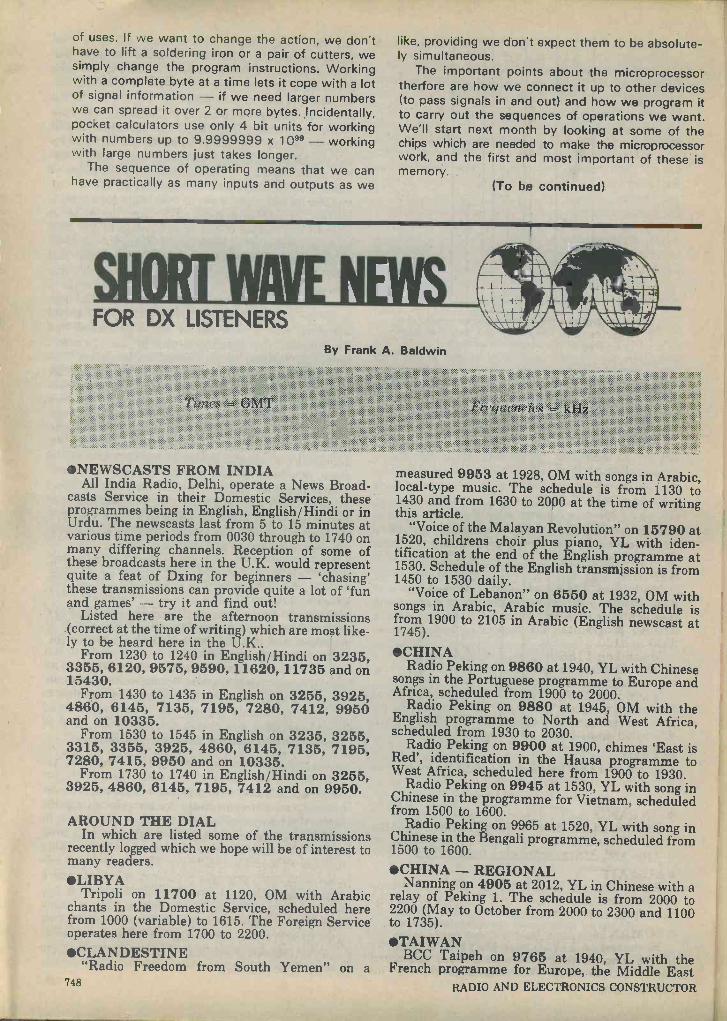
of uses. If we want to change the action, we don't have to lift a soldering iron or a pair of cutters, we simply change the program instructions. Working with a complete byte at a time lets it cope with a lot of signal information - if we need larger numbers we can spread it over 2 or more bytes. Incidentally, pocket calculators use only 4 bit units for working with numbers up to 9.9999999 x 1099 - working with large numbers just takes longer.
The sequence of operating means that we can have practically as many inputs and outputs as we
like, providing we don't expect them to be absolute- ly simultaneous.
The important points about the microprocessor therfore are how we connect it up to other devices (to pass signals in and out) and how we program it to carry out the sequences of operations we want. We'll start next month by looking at some of the chips which are needed to make the microprocessor work, and the first and most important of these is memory.
(To be continued)
FOR DX LISTENERS By Frank A. Baldwin
7`í trt.e4 0MT
NEWSCASTS FROM INDIA All India Radio, Delhi, operate a News Broad-
casts Service in their Domestic Services, these programmes being in English, English/ Hindi or in Urdu. The newscasts last from 5 to 15 minutes at various time periods from 0030 through to 1740 on many differing channels. Reception of some of these broadcasts here in the U.K. would represent quite a feat of Dxing for beginners - ̀ chasing' these transmissions can provide quite a lot of 'fun and games' - try it and find out!
Listed here are the afternoon transmissions (correct at the time of writing) which are most like- ly to be heard here in the U.K..
From 1230 to 1240 in English/ Hindi on 3235, 3355, 6120, 9575, 9590, 11620, 11735 and on 15430.
From 1430 4860, 6145, and on 1033
From 1530 3315, 3355, 7280, 7415,
From 1730 3925, 4860,
to 1435 in English on 3255, 3925, 7135, 7195, 7280, 7412, 9950
5. to 1545 in English on 3235, 3255, 3925, 4860, 6145, 7135, 7195, 9950 and on 10335. to 1740 in English/ Hindi on 3255, 6145, 7195, 7412 and on 9950.
AROUND THE DIAL In which are listed some of the transmissions
recently logged which we hope will be of interest to many readers. LIBYA
Tripoli on 11700 at 1120, OM with Arabic chants in the Domestic Service, scheduled here from 1000 (variable) to 1615. The Foreign Service operates here from 1700 to 2200.
CLANDESTINE "Radio Freedom from South Yemen" on a
748
measured 9953 at 1928, OM with songs in Arabic, local -type music. The schedule is from 1130 to 1430 and from 1630 to 2000 at the time of writing this article.
"Voice of the Malayan Revolution" on 15790 at 1520, childrens choir plus piano, YL with iden- tification at the end of the English programme at 1530. Schedule of the English transmission is from 1450 to 1530 daily.
"Voice of Lebanon" on 6550 at 1932, OM with songs in Arabic, Arabic music. The schedule is from 1900 to 2105 in Arabic (English newscast at 1745).
CHINA Radio Peking on 9860 at 1940, YL with Chinese
songs in the Portuguese programme to Europe and Africa, scheduled from 1900 to 2000.
Radio Peking on 9880 at 1945, OM with the English programme to North and West Africa, scheduled from 1930 to 2030.
Radio Peking on 9900 at 1900, chimes 'East is Red', identification in the Hausa programme to West Africa, scheduled here from 1900 to 1930.
Radio Peking on 9945 at 1530, YL with song in Chinese in the programme for Vietnam, scheduled from 1500 to 1600.
Radio Peking on 9965 at 1520, YL with song in Chinese in the Bengali programme, scheduled from 1500 to 1600.
CHINA - REGIONAL Nanning on 4905 at 2012, YL in Chinese with a
relay of Peking 1. The schedule is from 2000 to 2200 (May to October from 2000 to 2300 and 1100 to 1735).
TAIWAN BCC Taipeh on 9765 at 1940, YL with the French programme for Europe, the Middle East
RADIO AND ELECTRONICS CONSTRUCTOR
and Africa, scheduled from 1930 to 2020. Newscast until 1942 then YL with a song in Chinese. NORTH KOREA
Radio Pyongyang on 6600 at 2054, light music Euro-style, 4 low plus 1 high pitched `pips' time - check at 2100 followed by identification and news in the Korean Domestic Service, also logged in parallel on 11350. The schedule is from 2000 to 0830 and from 1500 to 1800. JAPAN
Tokyo on 9585 at 2104, OM with a newscast in English after station identification, schedule (in English and Japanese) is from 2100 to 2130. VATICAN
Vatican City on 9625 at 2001, YL with Rosary to Europe and Africa, scheduled here from 1945 to 2005 and also in parallel on 9645. ISRAEL
Jerusalem on 9815 at 2018, OM with the English programme to Europe, the Middle East, North America and South West Africa, scheduled from 2000 to 2030.
SEYCHELLES Mahe (FEBA) on 11860 at 1750, OM with the Arabic programme to North East Africa and the Middle East, YL with identification in this Far East Broadcasting Association transmission scheduled from 1700 to 1800.
MADAGASCAR Radio Netherlands Relay on 11730 at 1835, OM with a newscast in the English programme for
Africa, scheduled here from 1830 to 1920. GREECE
Athens on 11730 at 1546, YL with songs, typical Greek music in the Greek programme to North America, scheduled from 1500 to 1550. SPAIN
Madrid on 11840 at 2039, OM with news of local events - including maximum and minimum temperatures at many Spanish resorts - in the English programme for Europe, scheduled from 2030 to 2130.
Madrid on 11880 at 0550, YL with a newscast in the English programme to North America, scheduled from 0515 to 0615. Madrid on 11920 at 1130, YL with identifica- tion and a newscast in the Spanish programme for Latin America, North Africa and the Middle East,
scheduled from 1100 to 1235. ITALY
Rome on 11800 at 1940, YL with the local news in the English programme for the U.K., scheduled here from 1935 to 1955. FINLAND
Helsinki on 11755 at 1930, OM with news of the Nordic Countries in the English programme to Europe and Africa, scheduled from 1930 to 2000. KUWAIT
Radio Kuwait on 11990 at 1917, local -type music in the Arabic Domestic Service, scheduled here from 1830 to 2110. ROMANIA
Bucharest on 11720 at 0540, YL with the news in the English programme to Africa, scheduled from 0530 to 0600. Also logged in parallel on AUGUST, 1979
11830. Bucharest on 15335 at 0650, OM and YL alter- nate with news items in the English programme for the Pacific, scheduled from 0645 to 0715.
BURUNDI Bujumbura on 3300 at 1809, OM with the local news in French. This is the Home Service 1 in French and vernaculars, being scheduled here from
0330 to 0600 (Sundays through to 2100) and from 1500 to 2100 weekdays. The power is 25kW but the channel is anything but a good one! RWAN DA
Kigali on 3330 at 1813, OM with a newscast in French in the Home Service, scheduled here from 0300 to 0600 (Sunday until 0900), 0900 to 1200 (Saturday and Sunday until 2100) and from 1330 to 2100. The power is 5kW. ANGOLA
Luanda (R.Nacional) on 3355 at 1919, OM and YL alternate with announcements in Portuguese. The schedule is from 1530 to 2400 and the power is 10kW.
VENEZUELA Radio Occidente, Tovar, on 3225 at 0220,
religious service in Spanish, extended schedule - which is normally from 1030 to 0200. The power is 1kW.
Radio Universidad, Merida, on 3395 at 0230, OM with identification, jingles, LA music. The schedule is from 1000 to 0400 and the power is 1kW.
COLOMBIA Ecos del Combeima, Ibague, on 4875 at 0653,
OM with identification as "Radio Super" followed by Sambas etc. The schedule is on a 24 -hour basis and the power is 5kW.
Radio Cinco, Villavicencio on 5040 at 0659, OM with a lullaby in Spanish, OM with identification at 0701. The schedule is around the clock and the power is 3kW.
Emisora Nuevo Mundo, Bogata, on 4755 at 0500, OM with full identification followed by a newscast in Spanish. The schedule is around the clock and the power is 1kW.
Ondas del Meta, Villavicencio, on 4885 at 0453, OM with commercials, identification and Sambas etc. The schedule is from 0900 to 0500 and the power is 1kW.
ECUADOR Radio Popular, Cuenca, on a measured 4801 at
0507, OM with identification as "Radio Popular" (sometimes identifies as "Radio Amiga Popular de Cuenca"). The schedule is around the clock and the power is 2kW. This one is best received after Radio Lara, Barquisimeto, Venezuela, on 4800 closes at 0400.
Radio Splendit, Cuenca, on 5025 at 0242, OM with a love song in Spanish, OM with an- nouncements and identification at 0245. The schedule of this one is from 0900 to 0500 (variable 0430-0530) and sometimes around the clock. The power is 5kW.
BRAZIL Radio Aparecida, Aparicida, on 5035 at 0249,
OM with announcements in Portuguese, local -style dance music. The schedule is from 0900 to 0300 and the power is 1kW.
-749
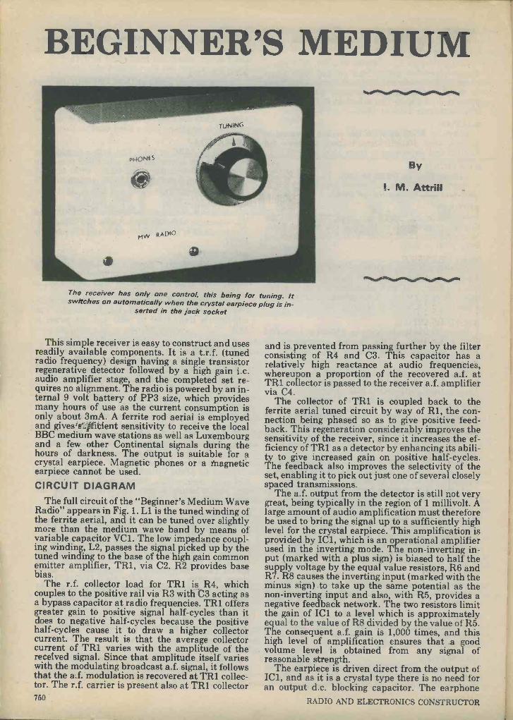
BEGINNER'S MEDIUM
The receiver has only one control, this being for tuning. It switches on automatically when the crystal earpiece plug is in-
serted in the jack socket
This simple receiver is easy to construct and uses readily available components. It is a t.r.f. (tuned radio frequency) design having a single transistor regenerative detector followed by a high gain i.c. audio amplifier stage, and the completed set re- quires no alignment. The radio is powered by an in- ternal 9 volt battery of PP3 size, which provides many hours of use as the current consumption is only about 3mA. A ferrite rod aerial is employed and givessltitient sensitivity to receive the local BBC medium wave stations as well as Luxembourg and a few other Continental signals during the hours of darkness. The output is suitable for a crystal earpiece. Magnetic phones or a iYiagnetic earpiece cannot be used.
CIRCUIT DIAGRAM The full circuit of the "Beginner's Medium Wave
Radio" appears in Fig. 1. Ll is the tuned winding of the ferrite aerial, and it can be tuned over slightly more than the medium wave band by means of variable capacitor VC1. The low impedance coupl- ing winding, L2, passes the signal picked up by the tuned winding to the base of the high gain common emitter amplifier, TR1, via C2. R2 provides base bias.
The r.f. collector load for TR1 is R4, which couples to the positive rail via R3 with C3 acting as a bypass capacitor at radio frequencies. TR1 offers greater gain to positive signal half -cycles than it does to negative half -cycles because the positive half -cycles cause it to draw a higher collector current. The result is that the average collector current of TR1 varies with the amplitude of the received signal. Since that amplitude itself varies with the modulating broadcast a.f. signal, it follows that the a.f. modulation is recovered at TR1 collec- tor. The r.f. carrier is present also at TRI collector 760
By
I. M. Attrill
W,010ftemooto mom
and is prevented from passing further by the filter consisting of R4 and C3. This capacitor has a relatively high reactance at audio frequencies, whereupon a proportion of the recovered a.f. at TR1 collector is passed to the receiver a.f. amplifier via C4.
The collector of TR1 is coupled back to the ferrite aerial tuned circuit by way of R1, the con- nection being phased so as to give positive feed- back. This regeneration considerably improves the sensitivity of the receiver, since it increases the ef- ficiency of TR1 as a detector by enhancing its abili- ty to give increased gain on positive half -cycles. The feedback also improves the selectivity of the set, enabling it to pick out just one of several closely spaced transmissions.
The a.f. output from the detector is still not very great, being typically in the region of 1 millivolt. A large amount of audio amplification must therefore be used to bring the signal up to a sufficiently high level for the crystal earpiece. This amplification is provided by ICI., which is an operational amplifier used in the inverting mode. The non -inverting in- put (marked with a plus sign) is biased to half the supply voltage by the equal value resistors, R6 and R7. R8 causes the inverting input (marked with the minus sign) to take up the same potential as the non -inverting input and also, with R5, provides a negative feedback network. The two resistors limit the gain of IC1 to a level which is approximately equal to the value of R8 divided by the value of R5. The consequent a.f. gain is 1,000 times, and this high level of amplification ensures that a good volume level is obtained from any signal of reasonable strength.
The earpiece is driven direct from the output of IC1, and as it is a crystal type there is no need for an output d.c. blocking capacitor. The earphone
RADIO AND ELECTRONICS CONSTRUCTOR
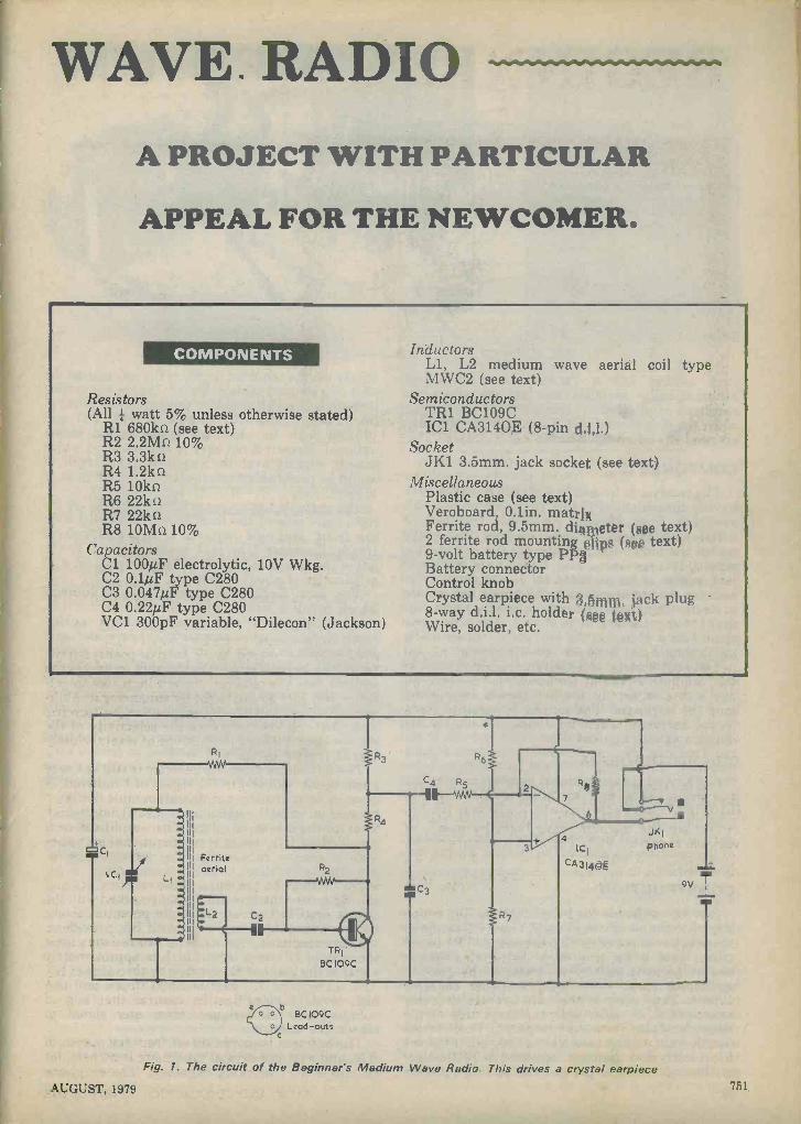
WAVE. RADIO A PROJECT WITH PARTICULAR
APPEAL FOR THE NEWCOMER.
COMPONENTS
Resistors (All ; watt 5% unless otherwise stated)
R1 6801m (see text) R2 2.2M0 10% R3 3.3kû R4 1.2kû R5 10kû R6 22ki R7 22kû R8 10Mû 10%
Capacitors Cl 100uF electrolytic, 10V Wkg. C2 0.l4F type C280 C3 0.047uF type C280 C4 0.22µF type C280 VC1 300pF variable, "Dilecon" (Jackson)
Inductors L1, L2 medium wave aerial coil type MWC2 (see text)
Semiconductors TR1 BC109C IC1 CA3140E (8 -pin dal)
Socket JK1 3.5mm. jack socket (see text)
Miscellaneous Plastic case (see text) Veroboard, 0.1in. matrjx, Ferrite rod, 9.5mm. dieter (see text) 2 ferrite rod mounting @lips (see text) 9 -volt battery type PP; Battery connector Control knob Crystal earpiece with 3,öriìm: jack plug 8 -way d.i.l. i.c. holder (@@@ t@1) Wire, solder, etc.
1=1 CI
c,7- II
Ferrite aerial
L2
C4
i
OM C3
7
4 ICI
CA -2140g
JK1 phone
T 9V 1
b
C
BC109C Lead -outs
Fig. 1. The circuit of the Beginner's Medium Wave Radio. This drives a crystal earpiece
AUGUST, 1979 761

jack socket has a "make" contact which automatically switches the set on when the earphone is plugged in, and switches it off again when the plug is removed. There is in consequence no need for an on -off switch.
COMPONENTS The receiver is housed in a plastic box type PB1,
having dimensions of 114 by 76 by 38mm., which is available from Maplin Electronic Supplies. A metal case cannot be used because this would screen the ferrite rod and prevent the reception of signals. It is necessary, also, for VC1 and the phone jack socket to be mounted on an insulated panel because the modification to the phone jack results in its mounting bush having a different potential to that at the mounting bush of VC1. The phone jack should be a type having an "open" construction, i.e. it should not have an insulated body.
The ferrite aerial coil and the CA3140E used for IC1 are both available from Ambit International, who can also supply the two plastic clips which hold the ferrite rod in place. As is described short- ly, the ferrite rod will in most instances have to be a longer rod which is cut down, and the longer rod required can also be obtained from Ambit Inter- national. (In passing it should be mentioned that the 1978 Ambit International catalogue states that the ferrite aerial coil specified is "not suited to bipolar descrete inputs." However, its characteristics are perfectly satisfactory for the particular circuit described here). The remainder of the components used in the receiver are general- ly available.
CONSTRUCTION The layout inside the plastic case can be seen in
the photograph of its interior. The ferrite rod is mounted at the bottom by the two Ambit plastic clips, these being secured to the front panel by short 6BA bolts with nuts. The ferrite rod requires a diameter of 9.5mm. and a length of about 100mm., and it is probable that difficulty will be experienced in obtaining a rod of this length. Because of this it may be necessary to obtain the length from a longer rod. The procedure here is to file a fairly deep V-shaped groove all round the rod at the point where it is to be broken and to then
lightly tap the required length of the rod against the edge of a wooden table or bench. It does not matter if there is a rough finish to the rod at the point of the break. Rods with lengths of 140, 160 and 175mm. can be obtained from Ambit Inter- national. Since it is not easy to shorten a rod which is only slightly over the required final length, it would be preferable to start off with the 160mm. or 175mm. rod.
The variable tuning capacitor is mounted on the right hand side of the front panel, as viewed from the front, and this requires a mounting hole of 10mm. diameter. The jack socket is fitted to the left of the tuning capacitor and requires a hole with a diameter of about 6.5mm.
The jack socket will normally have contacts which break a circuit when the plug is inserted, these usually being employed to mute a speaker when an earphone is connected. The appearance of the contacts is as shown in Fig. 2(a). It is merely necessary to carefully bend back the thicker fixed contact and then bend it downwards so that it is below the springy moving contact. The fixed con- tact should be finally positioned so that, without a plug inserted, the moving contact does not touch it. At the same time the two contacts should connect together when the plug is inserted in the socket.
Apart from the battery and its connector, the remaining components are assembled on a
Contacts not touching
(a) (b)
Fig. 2(a). The rear ends of the contacts of the jack socket before modification
lb). One of the contacts is bent so that the two contacts only make when the jack plug is in-
serted 752 RADIO AND ELECTRONICS CONSTRUCTOR

q
Battery clip
F
G H
Ferrite aerial
O 0 0 0 0 0
O 0 o R30 0
O 0 0
oc
0
O o R5
O 0 0
C40 O 0 0
R2°
O 0 0 0 0 0 0
O 0 0 0 0 0
O 0 o o
O 0 0
0 0 0 0 0 0
II 13 15 17 19 o 0 0 0 0 0 0 0 0 0 0 0 0 o o o o (o) o o o 0 0 o 0 0
o o o (o)o (o)o o 0 0 0 0 0 0 0 o 0 0 0 o(o)o o 0 0
o o o (o ) o ( o) o o 0 0
o 0 0 0 0(0)0 0 0(o)o 0 0 0 0
0 0 0 0 0 0 0 o ro o 0 0 a O
0 0 0 0 0 0 0 0 0 0 0 0 0 0 0 0 0 0 0
0 0 0 0 0 0 0 0 0 0 0 0 0 0 0 0 0
Fig. 3. Component layout on the Veroboard panel and the general wiring of the receiver
Veroboard of O.lin. matrix having 19 holes by 9 copper strips. Details of this panel are given in Fig. 3, which also illustrates all the point-to-point wir- ing of the receiver.
Start by cutting out the Veroboard to the correct size using a hacksaw, and then make the eight breaks in the copper strips. The breaks can be made with a Vero spot face cutter or a small twist drill held in the hand. The three link wires and the components should then be soldered to the board at the positions indicated in Fig. 3.
IC1 should be the last component to be soldered to the board. This device has a PMOS input stage and it can be damaged by high static voltages if these should appear at the inputs. The i.c. will almost certainly be supplied with its pins imbedd- ed in a piece of metal foil or conductive foam, and it should not be removed from this until it is time for it to be connected into circuit. All soldering should be carried out with an iron having a reliably earthed bit. Chances of accidental damage are much reduced if an 8 -pin i.c. holder is employed. This holder is soldered to the board in place of the i.c., and the latter is then inserted in the holder at a late stage of the construction.
The point-to-point wiring is next carried out, and it should be noted that one lead of R1 is soldered to strip "C" on the copper side of the board. Its other lead connects to the fixed vanes tag of VC1, as shown. The leads to the jack socket, to VC1 and to the aerial coil employ single strand p.v.c. covered wire, and they should be kept short and direct. It AUGUST, 1979
will then be found that they are sufficient to hold the component board in position, making any further mounting unnecessary. The board fits into the space between the jack socket and the ferrite aerial, with the component side towards the aerial and C3 nearest VC1. Its position is clearly shown in the photograph of the inside of the receiver case. The battery is fitted above the phone jack and may be held in place by means of Bostik Blue Tack.
If any difficulty is experienced in identifying the tags of Ll and L2, this should be cleared up by visually inspecting the coil and comparing it with the circuit diagram of Fig. 1. It should then be ap- parent which two tags connect to the negative supp- ly rail and which connect to VC1 and C2.
ADJUSTMENT Provided that the aerial coil is positioned right at the end of the ferrite rod the set should work cor- rectly without any alignment. If it does not, switch off at once and check the wiring thoroughly for errors. It is just possible that the regeneration provided by R1 is too great, causing the detector to oscillate and resulting in a whistle of varying pitch as the set is tuned across a station. This is unlikely but, should it occur, the trouble can be cured by ex- perimentally increasing the value of R1 until satisfactory results are obtained. It is more likely that the level of regeneration will be below optimum, but this will not prevent the
753
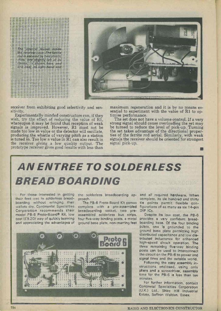
ï&is:ËG
ei fyra irnsde <';
ferrite `: ................. ................. tÏSiiGr::: ..............
8 :WO iix?;is1ï
.1114" ä , . -
receiver from exhibiting good selectivity and sen- sitivity.
Experimentally minded constructors can, if they wish, try the effect of reducing the value of R1, whereupon it may be found that reception of weak signals is improved. However, R1 must not be made too low in value or the detector will oscillate, producing the whistle of varying pitch as a station is tuned in. Too low a value in R1 can also result in the receiver giving a low quality output. The prototype receiver gives good results with less than
maximum regeneration and it is by no means es- sential to experiment with the value of R1 to op- timise performance.
The set does not have a volume control. If a very strong signal should cause overloading the set may be turned to reduce the level of pick-up. Turning the set takes advantage of the directional proper- ties of the ferrite rod aerial. Similarly, with weak signals the receiver should be oriented for strongest signal pick-up.
AN ENTREE TO SOLDERLESS BREAD BOARDING
For those interested in getting their feet wet in solderless bread - hoarding without wringing their wallets dry, Continental Specialties Corporation recommends their model PB -6 Proto -Board® Kit, low cost (£9.20) way of quickly learning and appreciating the advantages of
the solderless breadboarding ap- proach.
The PB -6 Proto -Board Kit comes complete with a pre -assembled breadboarding socket, two pre - assembled solderless bus strips, four five -way binding posts, a metal ground base plate, non -marring feet
and all required hardware. When complete, its six hundred and thirty tie points permit flexible con- figurations of as many as six 14 -pin DIP ICs.
Despite its low cost, the PB -6 provides a very confident bread- boarding base. Of the four binding pò ts, one is grounded to the ground base plate permitting high distributed capacitance and low dis- tributed inductance for enhanced high-speed circuit operation. The three remaining five -way binding posts can be used to interconnect the circuit on the PB -6 to power and signal lines and the outside world.
Following the easy assembly in- structions enclosed, using only pliers and a screwdriver, assembly time for the PB -6 is less than ten minutes.
For further information, contact Continetal Specialties Corporation (U.K.) Ltd., Shire Hill Industrial Estate, Saffron Walden, Essex.
54 RADIO AND ELECTRONICS CONSTRUCTOR

TUNE -IN TO PROGRAMS PART 7
By Ian Sinclair
BUG HUNTING We've all done it - we've written a program,
checked it, entered it into the machine and all we get when we run it is a flashing display or a silly answer. Obviously something's wrong, but what? There are several things we can do, some with the calculator, some without, to debug a program, but before we start we should check the following:
1. Is each store loaded up with the numbers that are to be used in the calculation?
2. Is each [STO], [RCL], [GTO], [Lbl] or ESBR] in- struction followed by the correct reference number?
3. Have we used an [=1 or [)] to complete calculations where these are needed? Some operations, like (11x], do not need [_], others, like [+1 [-] [X] [2.4 do. If in doubt, check out a sum with the calculator used simply as a calculator (not run- ning a program).
PROGRAM CHECK A particularly good way to check a program
before running it on the calculator is to imagine yourself as the calculator, writing down the effect of each instruction and acting on the number you have written down with the next instruction. This way, if we do only what the program dictates, we can often spot omitted [=1 or other signs which make a calculation impossible or incorrect.
If the program seems perfectly correct (and if it has run before then it must be correct), the next step is to check that this is the program that is actually entered. We may quite easily have missed a step or even added one which was not intended. How, then, do we trace through a program?
The answer is that the TI -57, along with the PR - 100, has editing facilities, enabling us to look at each step of a program which is in store. To make use of these facilities load up the memories as re- quired by the program, set up just as you would for running the program, press ERST] so that the program is reset to the beginning, and then press the [LAN] key.
The display then splits off, as in Fig. 1, to show the program step number on the left, along with the code number for the program instruction on the right. Remember your step codings? The code is a
AUGUST, 1979
2tr#
D.M8 LAN
Psuss
SST
Nop BST
Dat
GTO
.:_t SBf2
AST
en H!s
Ti Programmable 57
iop C t INV .
{nx CE GUI
P*+R sEn
xat x ins Exc
STO RGL
E)s1
CE
0
Fix
cue ten t/x
Prd 7{
SUAI Y
In! 11
The keyboard of the Texas Instruments T1=57 programmable calculator. Most keys have a second function, whereupon facilities are needy double the number of keys
provided
two -digit number in which the first digit represents the key row, starting at the display end of the calculator. The second digit represents the key column, starting at the left hand side with number 1, and moving from left to right along the normal func- tions (the ones printed on the keys) then back again at No. 6 to number the upper functions (marked above the keys and again from left to right). Ex- amples of these key codings are shown in Fig. 2. Any number in addition to the two -digit key code is a reference number such as a memory number, a
label number, etc.
Step No. (3)
03 51
Operation (GTO)
4
Ref. No. (label 4)
This is then the fourth step of the program, GTO 4. The first step is 00.
Fig. 1.

[INV] always codes as [-] before the operation code, so that [INV] [SBR] is [-61], [INV] [sin] (or arcsin) is [-28], and so on. Numbers are not coded, but entered normally.
Operation Code Operation Code
Pause 36 yX 35
GTO 51 sin 28
Dsz 56 cos 29
SBR 61 tan 20
x =t 66 43
RST 71 44
R/S 81 - 45
Lbl 86 X 55
STO 32 65
RCL 33 + 75
SUM 34 85
X2 23 +/- 84
.!z 24 log 18
1 Ix 25 antilog -18
Fig. 2. SOME IMPORTANT KEY CODINGS
In this condition, we can check the program step by step, using the [SST] key. Pressing the [SST] key advances the program by one step, showing the step number and the code for the operation that will be carried out. The [BST] key has a similar effect, but runs the program one step back on each press. Take great care not to press any other key uninten- tionally while a program is being checked in this way, because the machine is in the learn mode. This, in plain language, means that the [LRN] key has been pressed once, so that anything that is keyed in will become part of the program, wiping out the step that was present before. If you want to carry out a quick calculation without affecting the program you will have to press [LRN] again, so that the display returns to normal, showing a single zero.
You may not, of course, have to go through the whole program. When an error occurs which results in a flashing display, you can use the [RIS] and [CLR] (or [CE]) keys to freeze everything, then press 756
[LRN]. That should get you to the place where things started to go ape, so you can backstep using [BST] until you find what went wrong. Another possibility is that you may have a hunch that the root of the trouble is around step 25. You can get there by the key sequence [GTO] [2nd] [25] [LRN], which will result in the machine showing step 25. Once there, you can [SST] and [BST] your way around until you find the trouble. Note, by the way, that this [GTO] method needs a two -digit number. If, for example, you are looking for step 7 and you press [GTO] [2nd] [7], the machine will look for label 7. To get program step 7, you must key in [GTO] [2nd] [07] - the use of two digits makes a great difference.
You still can't see where it's gone wrong? There's still hope for you because we can also check what the calculator does to each number. Enter in a nice easy set of numbers, like 1, 2, 3, into the memories that are to be used. Calculate what the result of each step should be. Now load up the program in the usual way, press [RST] when the machine is out of program mode (after the second press of [LRN]) and, instead of pressing [R/S], press [SST]. What will be displayed this time will be the result of the first step of the program. For example, if the program starts with [RCL] [1], and memory 1 is
loaded with the number 1, then pressing [SST] at the start of this program will bring a 1 into the dis- play. The next press of the [SST] key carries out the next instruction. If the next step is 1+], [-], [X] or [-], the display does not change. Instructions like [1/x], [fix] or [x2] will cause the results of such steps to be displayed. This way, we can [SST] our way through the program looking at the results. Note that [BST] does not work in this mode. The results should agree with the old-fashioned artithmetic which you tried earlier. If it doesn't agree somewhere, you've found the fault.
EDITING Both the TI -57 and the PR -100 allow a number
of editing operations to be carried out on programs which are in store. These operations are insertion, replacement and deletion. Of these, the easiest edit is to write over a program step. You may find, for ex- ample, that your written program says [5] [SUM] [2], and the program in the calculator is displayed as
25 32 2, meaning that this is step 25 and that the key strokes programmed were [STO] [2] (since 32 is
the code for [STO]). Note that the PR -100 shows these as separate steps since merged codes are not used.
While the calculator is in the [LRN] mode, this in- correct program step can be written over simply by keying in [SUM] [2] in place of the [STO] [2] which was there. Once this is done, the display will show the next step of the program, so that we have to use the [BST] key to go one step back to check that the program is now as we want it.
Another editing step which is sometimes useful is
the [Nop] step (obtained by pressing [2nd] [BST]). When the program is being checked in the [LRN] mode, any step can be erased by using [Nop] (No-
RAI)IO AND ELECTRONICS CONSTRUCTOR
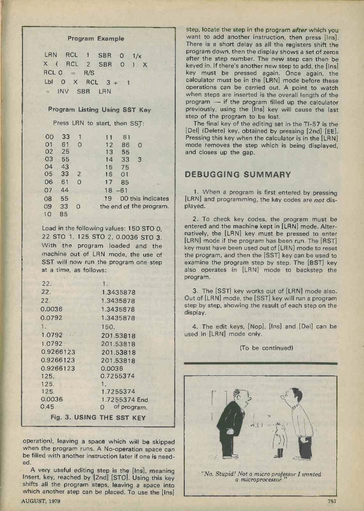
Program Example
LRN RCL 1 SBR 0 1/x X ( RCL 2 SBR 0 ) X RCLO = RIS
Lbl 0 X RCL 3 + 1
= INV SBR LRN
Program Listing Using SST Key
Press LRN to start, then SST:
00 33 1 11 81 01 61 0 12 86 0 02 25 13 55 03 55 14 33 3 04 43 15 75 05 33 2 16 01 06 61 0 17 85 07 44 18 -61 08 55 19 00 this indicates 09 33 0 the end of the program. 10 85
Load in the following values: 150 STO 0, 22 STO 1, 125 STO 2, 0.0036 STO 3. With the program loaded and the machine out of LRN mode, the use of SST will now run the program one step at a time, as follows:
22. 1.
22. 1.3435878 22. 1.3435878 0.0036 1.3435878 0.0792 1.3435878 1. 150. 1.0792 201.53818 1.0792 201.53818 0.9266123 201.53818 0.9266123 201.53818 0.9266123 0.0036 125. 0.7255374 125. 1.
125. 1.7255374 0.0036 1 .7255374 End 0.45 0 of program.
Fig. 3. USING THE SST KEY
operation), leaving a space which will be skipped when the program runs. A No -operation space can be filled with another instruction later if one is need- ed.
A very useful editing step is the [Ins], meaning Insert, key, reached by [2nd] [STO]. Using this key shifts all the program steps, leaving a space into which another step can be placed. To use the [Ins] AUGUST, 1979
step, locate the step in the program after which you want to add another instruction, then press [Ins]. There is a short delay as all the registers shift the program down, then the display shows a set of zeros after the step number. The new step can then be keyed in. If there's another new step to add, the [Ins] key must be pressed again. Once again, the calculator must be in the [LRN] mode before these operations can be carried out. A point to watch when steps are inserted is the overall length of the program if the program filled up the calculator previously, using the [Ins] key will cause the last step of the program to be lost.
The final key of the editing set in the TI -57 is the [Del] (Delete) key, obtained by pressing [2nd] [EE]. Pressing this key when the calculator is in the [LRN] mode removes the step which is being displayed, and closes up the gap.
DEBUGGING SUMMARY
1. When a program is first entered by pressing [LRN] and programming, the key codes are not dis- played.
2. To check key codes, the program must be entered and the machine kept in [LRN] mode. Alter- natively, the [LRN] key must be pressed to enter [LRN] mode if the program has been run. The [RST] key must have been used out of [LRN] mode to reset the program, and then the [SST] key can be used to examine the program step by step. The [BST] key also operates in [LRN] mode to backstep the program.
3. The [SST] key works out of [LRN] mode also. Out of [LRN] mode, the [SST] key will run a program step by step, showing the result of each step on the display.
4. The edit keys, [Nop], [Ins] and [Del] can be used in [LRN] mode only.
(To be continued)
"No, Stupid! Not a micro professor I wanted a microprocessor."
757
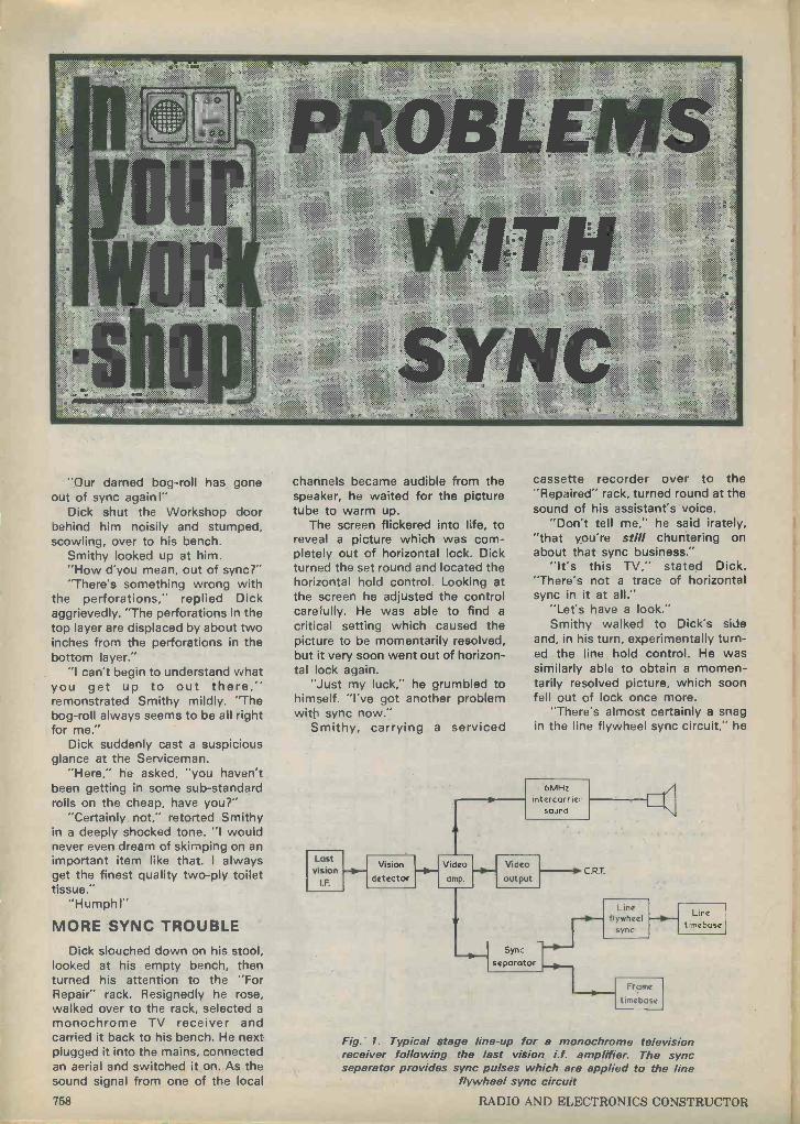
"Our darned bog -roll has gone out of sync again l"
Dick shut the Workshop door behind him noisily and stumped, scowling, over to his bench.
Smithy looked up at him. "How d'you mean, out of sync?" "There's something wrong with
the perforations," replied Dick aggrievedly. "The perforations in the top layer are displaced by about two inches from the perforations in the bottom layer."
"I can't begin to understand what you get up to out there," remonstrated Smithy mildly. "The bog -roll always seems to be all right for me."
Dick suddenly cast a suspicious glance at the Serviceman.
"Here," he asked, "you haven't been getting in some sub -standard rolls on the cheap, have you?"
"Certainly not," retorted Smithy in a deeply shocked tone. "I would never even dream of skimping on an important item like that. I always get the finest quality two-ply toilet tissue."
"Humph!"
MORE SYNC TROUBLE
Dick slouched down on his stool, looked at his empty bench, then turned his attention to the "For Repair" rack. Resignedly he rose, walked over to the rack, selected a
monochrome TV receiver and carried it back to his bench. He next plugged it into the mains, connected an aerial and switched it on. As the sound signal from one of the local
channels became audible from the speaker, he waited for the picture tube to warm up.
The screen flickered into life, to reveal a picture which was com- pletely out of horizontal lock. Dick turned the set round and located the horizontal hold control. Looking at the screen he adjusted the control carefully. He was able to find a
critical setting which caused the picture to be momentarily resolved, but it very soon went out of horizon- tal lock again.
"Just my luck," he grumbled to himself. "I've got another problem with sync now.",
Smithy, carrying a serviced
cassette recorder over to the "Repaired" rack, turned round at the sound of his assistant's voice.
"Don't tell me," he said irately, "that you're still chuntering on about that sync business."
"It's this TV," stated Dick. "There's not a trace of horizontal sync in it at all."
"Let's have a look." Smithy walked to Dick's side
and, in his turn, experimentally turn- ed the line hold control. He was similarly able to obtain a momen- tarily resolved picture, which soon fell out of lock once more.
"There's almost certainly a snag in the line flywheel sync circuit," he
6MHz intercarrier
sound
Last vision
Vision Video Video -- I.F.
detector amp. output - C.RS
Sync
separator
Line flywheel
sync
Frame
timebase
Line timebase
Fig. 1. Typical stage line-up for a monochrome television receiver following the last vision i.f. amplifier. The sync separator provides sync pulses which are applied to the line
flywheel sync circuit
758 RADIO AND ELECTRONICS CONSTRUCTOR

pronounced, as he switched off the set. "We're getting a picture and we can hear the intercarrier sound, So there must be a signal getting through all the way to the video out- put stage. Also, we're getting frame hold, which means that the sync separator circuits are at least pass- ing frame sync pulses to the vertical timebase. Since we're able to get the line timebase on to the correct frequency, even if only momentarily, that timebase can be assumed to be all right. All that's left is the horizon- tal flywheel sync circuit." (Fig. 1).
"How d'you know that this set has got a flywheel sync circuit? Couldn't it have direct line sync, in which the line sync pulses trigger the horizontal timebase oscillator?" (Fig. 2).
"Direct line sync went out of use ages ago," replied Smithy. "You might come across it in some ex- tremely old valve TV sets, but you certainly won't find it in any solid- state sets like the one you've got there. Apart from some of the most recent sets, which have got the line oscillator and sync stages packed away inside an integrated circuit, line flywheel sync arrangements have become standardised with
EAAD
Ikn
IOOkn
Vision detector R.F.0
Flyback
-i r Scan
Sync pulses
1
1
1
1
1
I
1
Fig. 2. Graphical presentation illustrating the action of a direct line sync system. The waveform represents a signal in the line timebase oscillator, and the sync pulse initiates the start of the flyback period before it would naturally occur. If the sync pulse were absent the waveform would continue as shown in broken
line
time as an inexpensive and reliable circuit which uses two silicon diodes connected in series. These two diodes are caused to become conductive when the transmitted line sync pulses are passed to them. Let's get out the service manual for this set and l'll show you."
Quickly forgetting his complaints about the Workshop's ultra -mural
e2Mn
Sync sep
To video output stage
eI OO k
'Phase splitter
470n
0-01}1F
facilities, Dick rose with alacrity and made his way to the filing cabinet. He soon found the appropriate ser- vice manual and brought it back to his bench opening it out at its circuit diagram.
"There you are," said Smithy, pointing to a section of the circuit. "There are the two flywheel sync diodes." (Fig. 3).
Flywheel sync diodes
- I +
470 n
IOkn /1NO-- ._ Line hold fr
V +
10 ....
O-01y1F a -
O
IOkn
0 221F
2-7 Line osc. kn freq. control
voltage
120n
2.2pF
0-047
T NF 2-7kn
300pF
+24V
11
I
LInc
11 output
Il transformer lIl
Ill III
Fig. 3. Slightly simplified circuit representative of monochrome TV practice illustrating how the line sync pulses are fed to the two flywheel sync diodes to turn them on in the presence of the pulses. The components between the line output transformer winding and the sync diodes
provide waveform shaping AUGUST, 1979 759
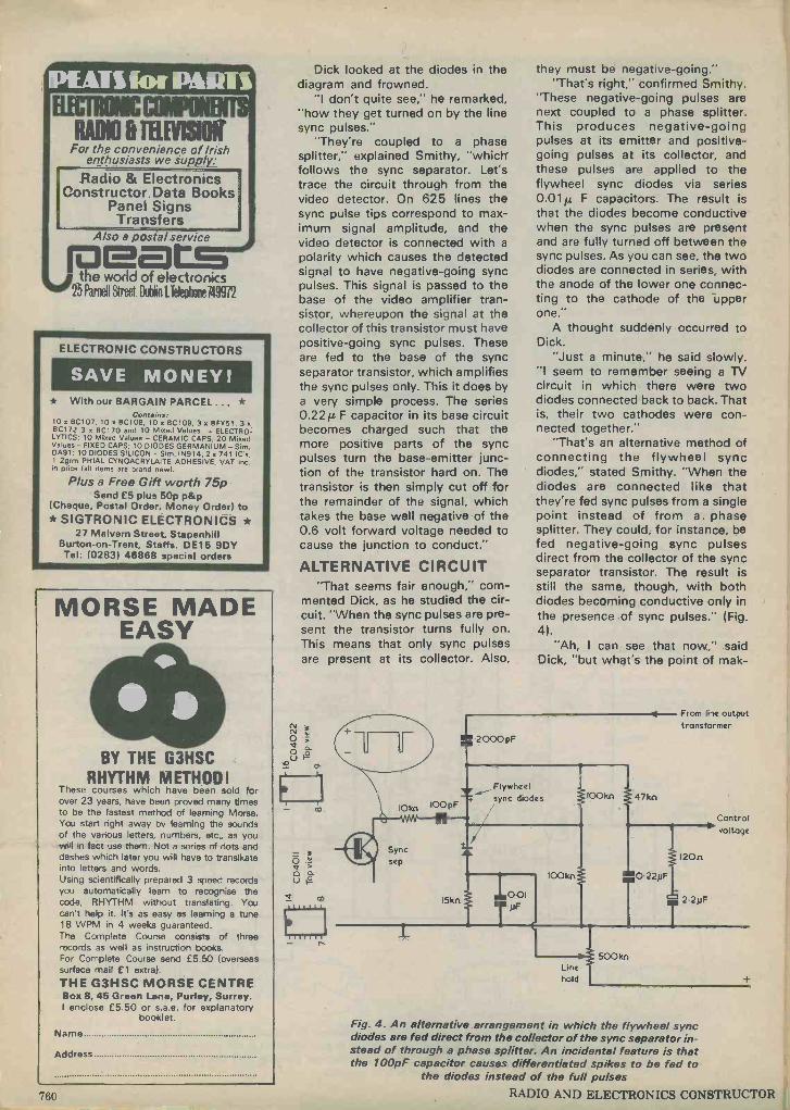
EOM RADIO IRENE)"
For the convenience of Irish enthusiasts we supply:
Radio & Electronics Constructor. Data Books
Panel Signs Transfers
Also a postal service BmtsB#
23
the world of electronics Parnell Street. DuhI IlTelepholleJ49972
ELECTRONIC CONSTRUCTORS
SAVE MONEY! * With our BARGAIN PARCEL ... *
Contains: 10x8C107, 10xBC108, 10x BC109, 3xBFY51. 3x BC1 72 3 r 8C170 and 10 Mixed Values - ELECTRO- LYTICS: 10 Mixed Values - CERAMIC CAPS; 20 Mixed Values - FIXED CAPS; 10 DIODES GERMANIUM -Sim. OA91; 10 DIODES SILICON - Sim, IN914; 2 x 741 IC's,
1 2grm PHIAL CYNOACRYLAITE ADHESIVE, VAT inc. in price (all items are brand new).
Plus a Free Gift worth 75p Send £5 plus 50p p&p
(Cheque, Postal Order, Money Order) to * SIGTRONIC ELECTRONICS *
27 Malvern Street, Stapenhill Burton -on -Trent, Staffs. DE15 9DY Tel: (0283) 46888 special orders
MORSE MADE EASY
(t) BY THE G3HSC
RHYTHM METHOD! These courses which have been sold for over 23 years, have been proved many times to be the fastest method of learning Morse. You start right away by learning the sounds of the various letters, numbers, etc., as you will in fact use them. Not a series of dots and dashes which later you will have to translkate into letters and words. Using scientifically prepared 3 speed records you automatically learn to recognise the code, RHYTHM without translating. You can't help it. It's as easy as learning a tune 18 WPM in 4 weeks guaranteed. The Complete Course consists of three records as well as instruction books. For Complete Course send £5.50 (overseas surface mail £1 extra).
THE G3HSC MORSE CENTRE Box 8, 45 Green Lane, Purley, Surrey. I enclose £5.50 or s.a.e. for explanatory
booklet.
Name
Address
760
Dick looked at the diodes in the diagram and frowned.
"I don't quite see," he remarked, "how they get turned on by the line sync pulses."
"They're coupled to a phase splitter," explained Smithy, "which follows the sync separator. Let's trace the circuit through from the video detector. On 625 lines the sync pulse tips correspond to max- imum signal amplitude, and the video detector is connected with a
polarity which causes the detected signal to have negative -going sync pulses. This signal is passed to the base of the video amplifier tran- sistor, whereupon the signal at the collector of this transistor must have positive -going sync pulses. These are fed to the base of the sync separator transistor, which amplifies the sync pulses only. This it does by a very simple process. The series 0.221£ F capacitor in its base circuit becomes charged such that the more positive parts of the sync pulses turn the base -emitter junc- tion of the transistor hard on. The transistor is then simply cut off for the remainder of the signal, which takes the base well negative of the 0.6 volt forward voltage needed to cause the junction to conduct."
ALTERNATIVE CIRCUIT "That seems fair enough," com-
mented Dick, as he studied the cir- cuit. "When the sync pulses are pre- sent the transistor turns fully on. This means that only sync pulses are present at its collector. Also,
m
15kn
L
they must be negative -going." "That's right," confirmed Smithy.
"These negative -going pulses are next coupled to a phase splitter. This produces negative -going pulses at its emitter and positive - going pulses at its collector, and these pulses are applied to the flywheel sync diodes via series 0.01A F capacitors. The result is that the diodes become conductive when the sync pulses are present and are fully turned off between the sync pulses. As you can see, the two diodes are connected in series, with the anode of the lower one connec- ting to the cathode of the upper one."
A thought suddenly occurred to Dick.
"Just a minute," he said slowly. "I seem to remember seeing a TV circuit in which there were two diodes connected back to back. That is, their two cathodes were con- nected together."
"That's an alternative method of connecting the flywheel sync diodes," stated Smithy. "When the diodes are connected like that they're fed sync pulses from a single point instead of from a. phase splitter. They could, for instance, be fed negative -going sync pulses direct from the collector of the sync separator transistor. The result is still the same, though, with both diodes becoming conductive only in the presence of sync pulses." (Fig. 4).
"Ah, I can see that now," said Dick, "but what's the point of mak-
2000pF
Flywheel sync diodes IO0kn 47kn
001 pF
IO0kn
Line hold
From line output transformer
1
500 kn
0-22}1F
120n
Control I> voltage
Fig. 4. An alternative arrangement in which the flywheel sync diodes are fed direct from the collector of the sync separator in- stead of through a phase splitter. An incidental feature is that the 100pF capacitor causes differentiated spikes to be fed to
the diodes instead of the full pulses RADIO AND ELECTRONICS CONSTRUCTOR
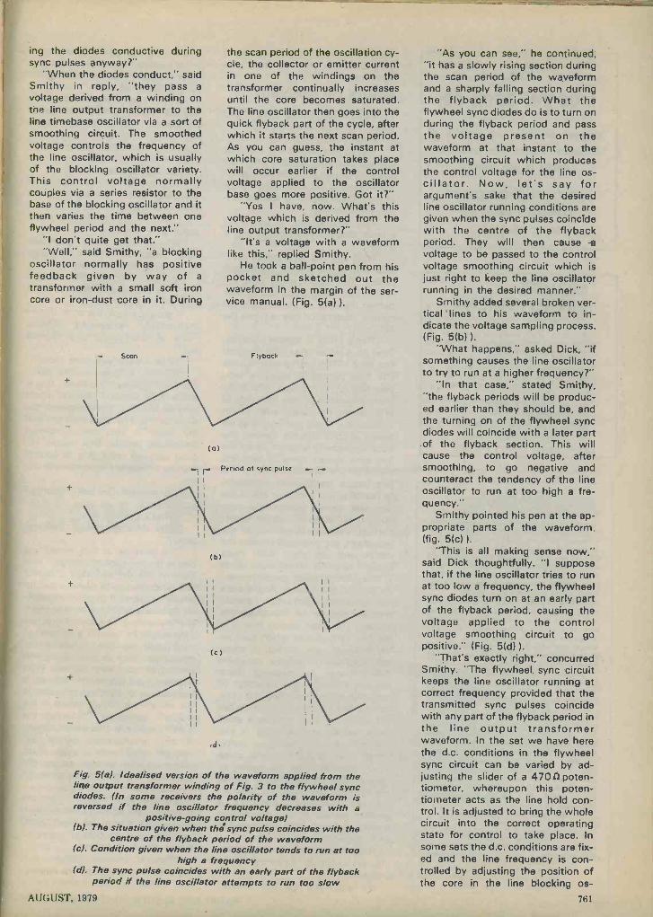
ing the diodes conductive during sync pulses anyway?"
"When the diodes conduct," said Smithy in reply, "they pass a
voltage derived from a winding on the line output transformer to the line timebase oscillator via a sort of smoothing circuit. The smoothed voltage controls the frequency of the line oscillator, which is usually of the blocking oscillator variety. This control voltage normally couples via a series resistor to the base of the blocking oscillator and it then varies the time between one flywheel period and the next."
"I don't quite get that." "Well," said Smithy, "a blocking
oscillator normally has positive feedback given by way of a
transformer with a small soft iron core or iron -dust core in it. During
Scan
(a)
the scan period of the oscillation cy- cle, the collector or emitter current in one of the windings on the transformer continually increases until the core becomes saturated. The line oscillator then goes into the quick flyback part of the cycle, after which it starts the next scan period. As you can guess, the instant at which core saturation takes place will occur earlier if the control voltage applied to the oscillator base goes more positive. Got it?"
"Yes I have, now. What's this voltage which is derived from the line output transformer?"
"It's a voltage with a waveform like this," replied Smithy.
He took a ball-point pen from his pocket and sketched out the waveform in the margin of the ser- vice manual. (Fig. 5(a) ).
Flyback
Period al sync pulsa
il
(b)
(c)
,d,
Fig. 5(a). Idealised version of the waveform applied from the line output transformer winding of Fig. 3 to the flywheel sync diodes. (In some receivers the polarity of the waveform is reversed if the line oscillator frequency decreases with a
positive -going control voltage) (b). The situation given when the sync pulse coincides with the
centre of the flyback period of the waveform (c). Condition given when the line oscillator tends to run at too
high a frequency (d). The sync pulse coincides with an early part of the flyback
period if the line oscillator attempts to run too slow
"As you can see," he continued, "it has a slowly rising section during the scan period of the waveform and a sharply falling section during the flyback period. What the flywheel sync diodes do is to turn on during the flyback period and pass the voltage present on the waveform at that instant to the smoothing circuit which produces the control voltage for the line os- cillator. Now, let's say for argument's sake that the desired line oscillator running conditions are given when the sync pulses coincide with the centre of the flyback period. They will then cause a
voltage to be passed to the control voltage smoothing circuit which is just right to keep the line oscillator running in the desired manner."
Smithy added several broken ver- tical lines to his waveform to in- dicate the voltage sampling process. (Fig. 5(b) ).
"What happens," asked Dick, "if something causes the line oscillator to try to run at a higher frequency?"
"In that case," stated Smithy, "the flyback periods will be produc- ed earlier than they should be, and the turning on of the flywheel sync diodes will coincide with a later part .of the flyback section. This will cause smoothing, to go negative and counteract the tendency of the line oscillator to run at too high a fre- quency."
Smithy pointed his pen at the ap- propriate parts of the waveform. (fig. 5(c) ).
"This is all making sense now," said Dick thoughtfully. "I suppose that, if the line oscillator tries to run at too low a frequency, the flywheel sync diodes turn on at an early part of the flyback period, causing the voltage applied to the control voltage smoothing circuit to go positive." (Fig. 5(d) ).
"That's exactly right," concurred Smithy. "The flywheel sync circuit keeps the line oscillator running at correct frequency provided that the transmitted sync pulses coincide with any part of the flyback period in the line output transformer waveform. In the set we have here the d.c. conditions in the flywheel sync circuit can be varied by ad- justing the slider of a 470f2poten- tiometer, whereupon this poten- tiometer acts as the line hold con- trol. It is adjusted to bring the whole circuit into the correct operating state for control to take place. In some sets the d.c. conditions are fix- ed and the line frequency is con- trolled by adjusting the position of the core in the line blocking os -
AUGUST, 1979 761
THE
MODERN BOOK CO.
Largest selection of English & American radio and technical
books in the country
19-21 PRAED STREET LONDON W2 1NP Tel: 01-402 9176
MORSE IMPROVEMENT C90 Cassettes IA) 1-12 w.p.m. with simple 'exercises. Suitable for R.A.E. preparation. (B) 12-24 w.p.m. computer produced professional level operator material including international symbols. Price each: complete with instruction and exercise booklets £4.50 including postage.
Morse Key and Buzzer Unit suitable for sending practice and DIY tape prepara- tion.
Price £4.50 including postage.
Overseas Airmail £1 extra.
MHEL ELECTRONICS (Dept. R!
12 Longshore Way, Milton, Portsmouth (UK), PO4 8LS
GAR EX V.H.F. Receivers SR -9 for 2 -metres F.M., fully tunable 144-146MHz, 2 -speed slow- motion dial, also 11 xtal controlled channels. Compact, sensitive, ideal for fixed or mobile listening. Built-in L.S., 12v D.C. operation £57.35 inc. VAT. Crystals, if required: £2.50 each. All popular 2m. channels in stock. Marine band version (156-162MHz) £57.35 (xtals £2.79). Mains psu for above £11.25. Credit terms available, s.a.e. details. Amplified Mobile Extn. Speaker boosts audio from small receivers. Single compact unit. 12vDC built-in 6W amplifier, with leads and jack plug, 4-8 (2 input £11.25. Amplifier only from above £2.70. Neons min wire end 55p/10; £4/100 Slide switches min DPDT 18p. ea; 5+: 14p Resistor Kits E12 series, 22n to 1M (2 57 values. 5% carbon film, *W or 1-W Starter pack, 5 each value )285) £2.95 Mixed pack, 5 each pW + .1W (570)£5.40 Standard pack, 10 each (570) £5.40 Giant pack, 25 each (1,425) £13.25 I.C's (new) 7410 25p CD4001AE 25p SN76660 75p NE555 55p 723)T05( 75p 709 (T05). 741 (DIL-8) Op.amps 30p; BNC Cable mtg socket 50 (2 20p; 5+-: 15p PL259 UHF Plug & Reducer 68p; 5+: 60p; S0239 UHF Socket panel mtd. 55p; 5+: 45p Nicad rechargeables phy- sically equiv. to zinc -carbon types: AAA (U16) £1.64; AA(U7) £1.20, C(U11) £3.15; D(U2) £4.94; PP3 £5.20 Any 5+: less 10%. Any 10+ less 20%.
We stock V.H.F. mobile aerials, s.a.e. details.
Distributors for J. H. Associates Ltd. (switches and lamps)
PRICES INCLUDE UK POST. PACKING & VAT Mail order only Sole Address:
GAREX ELECTRONICS 7 NORVIC ROAD, MARSWORTH,
TRING, HERTS HP23 4LS Cheddington (STD 0296) 688684
cillator transformer. This adjustment then becomes the line hold ad- justment."
RANGE OF CONTROL "There's something here," said
Dick, "that's puzzling me a bit." "What's that?" "You've just shown me that you
can get line synchronism when the line sync pulses coincide with either the beginning, the end or the middle of the flyback period of the line out- put waveform."
"Yes," said Smithy, "there's quite a wide range over which control is given."
"Well, say the sync pulses coin- cide with a late part of the flyback period. This could mean that the receiver will have gone into flyback before the end of the transmitted picture information has reached the set."
"That's true," agreed Smithy, "and it's a minor snag with flywheel line sync. When you've adjusted the line hold control to obtain a lock, you find that you can effectively move the whole picture from side to side within the range over which lock occurs. I said just now that we would assume that the desired line hold adjustment is given when the line sync pulses coincide with the centre of the flyback period of the line output transformer waveform. In practice, it is better to adjust the line hold control so that the sync pulses coincide with a rather earlier part of the flyback period in the waveform, say midway between the centre and the start. With most modern sets this will normally result in the picture being properly cen- tralised on the screen. And there's one other little point which i should mention before we finish on this subject. I've been saying that it is the line sync pulses which turn on the flywheel sync diodes. In some sets the sync pulses may be differentiated by passing them through a lowish value capacitor or capacitors before they hit the diodes. The result is that the diodes are turned on each time by a short spike whose leading edge is the leading edge of the sync pulse, rather than by the full sync pulse itself. The result is the same, of course, but the short spike allows the flywheel sync circuit to have in- creased resolution because a
smaller section of the line output transformer waveform is sampled in each cycle."
"Well," said Dick, "that certainly clears up this flywheel sync business."
He scowled as his earlier
grievances rose up in his mind. "It's a pity," he went on dismally,
"that we can't clear up the bog -roll sync problem as easily."
"If you keep on about that," warned Smithy sternly, "I'll get in some of that hard single layer public loo stuff. You won't have any problems with that going out of sync."
Dick was aghast. "You wouldn't," he said in a
trembling voice, "do anything like that, would you, Smithy?"
"I will if you don't stop com- plaining."
"Oh, all right then," grumbled Dick. "I suppose I'd better have a go at repairing this set, then."
He disconnected the receiver from the mains and proceeded to take off its back.
"I should check the sync diodes themselves," suggested Smithy. "One of them may have shorted out."
"What makes you think that?" "It's only a guess on my part,"
admitted Smithy. "However, if one diode has shorted out it would provide a circuit path between the slider of the 470(2line hold pot and the input to the control voltage smoothing circuit. That would ex- plain why we were able to control the line timebase frequency with the pot."
"Fair enough. I've just thought of something."
"What's that?" "Why do they call it 'flywheel
sync'?" "It's because of that smoothing
circuit for the control voltage," said Smithy. "In the old days of direct line sync, the line timebase could be falsely triggered if the receiver pick- ed up interference pulses, and you'd get line tearing. This meant that line sync would be lost for a number of lines until the line timebase os- cillator got back in step again with the transmitted sync pulses. With flywheel sync the control voltage is held steady by the first capacitor in
the smoothing circuit, which is the 0.22itF capacitor following the 2.7k(2 resistor in this particular set. If any interference pulses get through they won't have much effect on the voltage across the capacitor, and that's what gives the flywheel effect." (Fig. 6).
By now, Dick had unhinged the printed board and was examining it closely. He turned his head briefly and looked at the 0.22jiF capacitor in the circuit diagram.
"There's another resistor and capacitor in that circuit," he remark- ed. "There's a 120(2 resistor and a
762 RADIO AND ELECTRONICS CONSTRUCTOR

OOINF
-111
IOkn -WM-6 --- r
O OIpF
Flywheel sync
diodes
10 kn
IOkn
2.7kn
0 22pF
T0 047YF
Control
1120n
voltage
Fig. 6. Detail of the circuit of Fig. 3. The control voltage "smoothing" components are the 0.22pF capacitor, the 12012 resistor and the 2.2pF capacitor. The last two components also
reduce any tendency towards hunting in the sync system
2.2jtF electrolytic in series." "Those are anti -hunt com-
ponents," said Smithy. "If you just had the 0.22/2F capacitor on its own the circuit could have a tendency to hunt around the correct line fre- quency. It would be the same sort of hunting effect that you get in a ser- vomechanism. The resistor and the capacitor modify the time constant of the flywheel sync loop so that any
hunting that takes place is negligibly low. Have you located those two diodes yet?"
"Yes, I've just found them." "I should check them both ways
round with an ohmmeter," said Smithy. "If my hunch is right you'll soon be able to find the short- circuited one."
And, indeed, Smithy's prediction prove) to be correct, and Dick dis-
covered that the lower diode in the circuit diagram was now conducting fully in both directions.
PROBLEM SOLVED Smithy watched his assistant
contentedly as the latter went to the spares cupboard to find a new diode and then soldered it into circuit in place of the faulty one. He waited until Dick had checked the receiver, to find that the horizontal sync cir- cuit was now functioning properly, then quietly made his way out of the Workshop.
Over the years we have followed Smithy into many strange and out of the way places, and modesty would prevent us from accom- panying him on his present mission were it not for the fact that his ac- tions solve a minor little mystery. After he had settled himself comfor- tably, Smithy thoughtfully took the top ply of the paper positioned at his side and passed it once around the roll. The sets of perforations became aligned perfectly. Some time later he just as thoughtfully took the top ply once around the roll again, to give the out -of -sync characteristic which was proving so troublesome to his unsuspecting assistant.
a
New Product Z.I.P. D.I.P. SOCKET
The letters Z.I.P. stand for Zero Insertion Pressure and they are applicable to the dual -in -line i.c. holder shown in the accompanying photograph. The socket has been in- troduced by BFI Electronics Limited, 516 Walton Road, West Molesey, Surrey, KT8 OQF, and is currently available in 16 -pin. 24 -pin and 40 - pin versions will be in production in the near future.
Using the socket is extremely easy. The dual -in -line i.c. is simply dropped into the open socket, after which the small screw at the end is given a quarter turn. This clamps all the i.c. pins inside the socket and ensures excellent mechanical and electrical contact over the life of the i.c. and the socket. The i.c. can be released by turning the screw back to its original position, which will certainly make life easy for service personnel who wish to replace or check the i.c.
Known as the Textool "ECONO
AUGUST, 1979
ZIP" socket, the holder is designed as a low cost item with a limited number of clamping operations, but it still incorporates most of the features found in high quality
"lever -arm" clamping sockets. It is moulded in a UI -approved thermo- plastic and its contacts are plated to high standards for maximum life and minimum contact resistance.
The "ECONO ZIP" Zero Insertion Pressure i.c. socket, introduced by BFI Electronics Limited. The socket, which clamps the pins of in- tegrated circuit packages after insertion, is operated by turning the screw head on its upper
surface 763
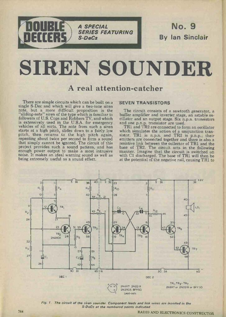
DUEL ECCER
A SPECIAL SERIES FEATURING S-DeCs
No. 9 By Ian Sinclair
SIREN SOUNDER A real attention -catcher
There are simple circuits which can be built on a single S -Dec and which will give a two-tone siren note, but a more difficult proposition is the "sliding -note" siren of the type which is familiar to followers of U.S. Cops and Robbers TV, and which is extensively used in the U.S.A. for emergency vehicles of all sorts. The note from such a siren starts at a high pitch, slides down to a fairly low pitch, then returns. to. the high pitch again, repeating about twice per second to form a sound that simply cannot be ignored. The circuit of this project provides such a sound pattern, and has enough power output to make a most intrusive noise. It makes an ideal warning sound as well as being extremely useful as a sound effect.
30 61
DEC I
65116
1
b
SEVEN TRANSISTORS
The circuit consists of a sawtooth generator, a buffer amplifier and inverter stage, an astable os- cillator and an output stage. Six n.p.n. transistors and one p.n.p. transistor are used.
TR1 and TR2 are connected to form an oscillator which simulates the action of a unijunction tran- sistor. TR1 is n.p.n. and TR2 is p.n.p.; their emitters are connected together and there is also a resistive link between the collector of TR1 and the base of TR2. The circuit acts in the following manner. Imagine that the circuit is switched on with Cl discharged. The base of TR1 will then be at the potential of the negative rail, causing TR1 to
2N697 2N2219 2N2905 BFY5O
Lead -outs
DEC 2
TR6
20 56
40
45
o +6V 39
t LS1
TR1,TR3- TR7
2N697 or 2N2219 or BFY 50
Fig. 1. The circuit of the siren sounder. Component leads and link wires are inserted in the S-DeCs at the numbered points indicated
764 RADIO AND ELECTRONICS CONSTRUCTOR

be cut off. The junction of R2 and R3 will be at about 2 volts positive of the negative rail and TR2 will also be cut off. This is because TR2 is a p.n.p. transistor, which requires the base to be negative of' the emitter if it is to conduct.
Cl charges through R1 at a rate determined by the time constant of these two components. When the voltage at point 12 of DeC 1 reaches a level of about 3.2 volts (the 2 volt bias at the base of TR2 plus two base -emitter voltage drops of 0.6 volt each) both TR1 and TR2 start to conduct. With TR1 con- ducting its collector voltage falls, so that the base voltage of TR2 falls also. The emitter current flow- ing in the transistors then turns them both hard on. Cl discharges very rapidly through the base - emitter junction of TRI and through TR2, the voltage across it falling to about 0.8 volt (the base - emitter voltage of TR1 plus a voltage of about 0.2 volt across TR2). The two transistors then turn off, Cl commences to charge again via R1 and another cycle starts.
The waveform at point 12 of DeC 1 is a sawtooth with a positive -going ramp, but we need a negative - going ramp to generate in a multivibrator a note which descends in pitch. We also need rather more amplitude if we are to provide a realistic sound. TR3 is a buffer amplifier which amplifies and in- verts the sawtooth. At point 43 of DeC 1, therefore, the waveform is a negative -going sawtooth with a peak -to -peak amplitude of about 6 volts.
ASTABLE OSCILLATOR
TR4 and TR5 form an astable oscillator with cross -coupling capacitors C3 and C4, and collector load resistors R10 and R11. This functions in the familiar multivibrator manner with the capacitors charging through R8 and R9. The rate of charging
COMPONENTS
Resistors (All 4 watt 5'-o) R1 150k s2
R2 22k II R3 12k si R4 1.8kiz R5 22kn R6 1.8k iz
R7 4.7k sa
R8 5Gk n R9 5Gk sa
R10 1.8k sZ
R11 1.8ksi R12 SGko
Capacitors Cl 10A F electrolytic, 16V Wkg. ('2 101.£ F electrolytic, 16V Wkg. C3 O.01µ, F polyester or mylar C4 0.01µ F polyester or mylar
Semtrnnductors TR1 2N697 or 2N2219 or BFY50 TR2 2N2905 TR3-TR7 2N697 or 2N2219 or BFY50
Speaker LS1 60s1 to 80n
Miscellaneous 2 -off S-DeC 6V battery
(see text)
AUGUST, 1979
IMn Linear
56kn
3
13
Fig. 2. A variable control of sawtooth frequency can be obtained by replacing R1 with a poten-
tiometer and fixed resistor in series
is faster if the charging resistors are returned to a high voltage, as consequently is the frequency of -os- cillation. R8 and R9 couple to the collector of TR3 and, at the start of each negative -going ramp of the sawtooth at this collector, the astable frequency will be high. The frequency falls as TR3 collector goes negative until, at the end of each sawtooth ramp, the frequency abruptly goes high again.
The square waves generated by the astable at the collector of TR5 are directly coupled to the output stage, which consists of emitter follower TR6 and the common emitter transistor, TR7. R12 ensures that the astable is not excessively loaded by driving the output stage, and the gain provided by TR6 en- sures that TR7 is driven between the fully bot- tomed and cut-off conditions. The loudspeaker should preferably be a high resistance type, with an impedance of 60n to 80n . However, a 15 sz speaker can also be used if your ears can stand it!
Several circuit changes can be made if needed. The range of notes can be shifted down in frequen- cy by replacing C3 and C6 with 0.02 µ F or 0.05i1 F capacitors. The rate of the sawtooth can be in- creased by connecting another 150k n resistor in parallel with R1. The added resistor can be in- serted in holes 4 and 14 of DeCl. The rate can be made variable by removing R1 and connecting a 1Mc potentiometer and a series 56kn resistor in its place, as indicated in Fig. 2. The 56kn resistor ensures that the potentiometer cannot be adjusted to a low resistance setting which would cause the sawtooth generator to "stick", with both TR1 and TR2 conducting heavily.
CONSTRUCTION
Start construction by clipping two S-DeCs together to form one long DeC. Connect the loudspeaker leads using single -core wire. If strand- ed wire must he used twist and tin the ends to en- sure that there are no loose strands. Plug in the wire links, seven in all, and also the two resistors. R8 and R9, which link the two DeCs together. Next plug in the capacitors, remembering that Cl and C2 are electrolytic and must be connected with cor- rect polarity. The transistors can now be plugged into circuit. TR2 is a p.n.p. type, but its lead -out layout is the same as the other transistors. The assembly of the astable follows the "mirror -image" style, with both emitters connected to the central line of the DeC. Finally, plug in all the remaining resistors.
Add the G volt battery leads and prepare to un- leash the siren -sound on an unsuspecting world.
765
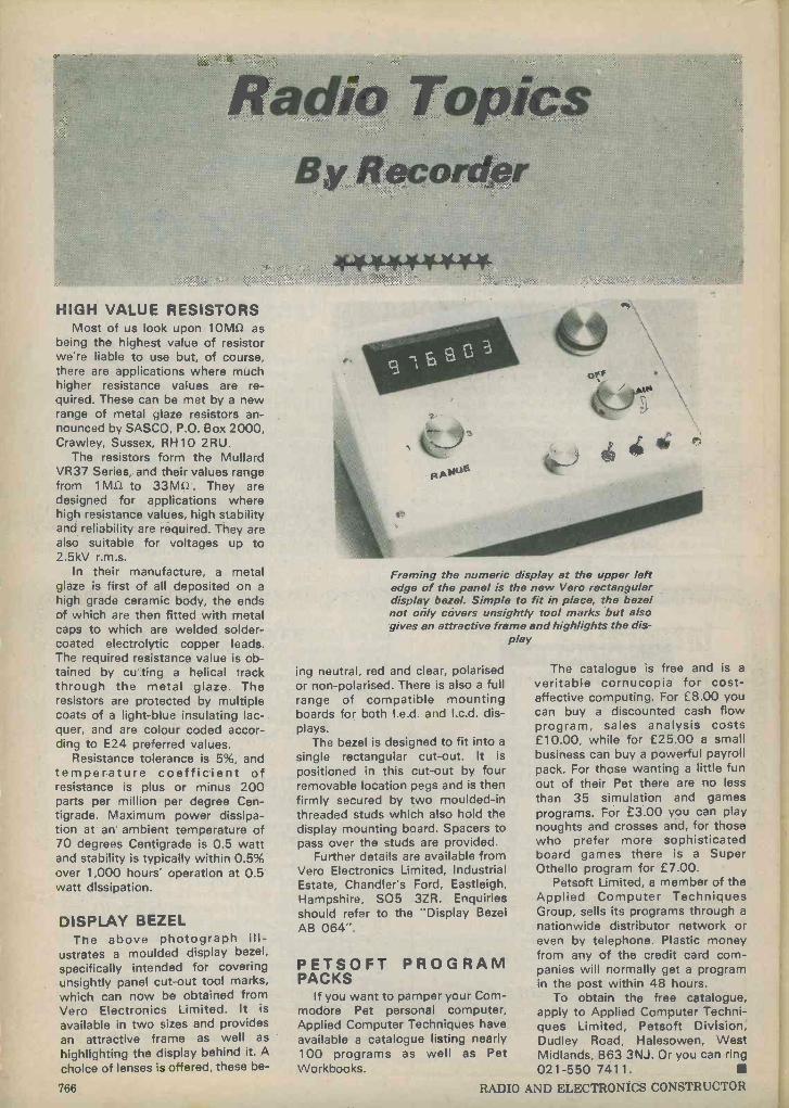
Radio Topics. By Recorder
44-4.44444*
HIGH VALUE RESISTORS Most of us look upon 101/1612 as
being the highest value of resistor we're liable to use but, of course, there are applications where much higher resistance values are re- quired. These can be met by a new range of metal glaze resistors an- nounced by SASCO, P.O. Box 2000, Crawley, Sussex, RH10 2RU.
The resistors form the Mullard VR37 Series, and their values range from 1M12 to 33MQ . They are designed for applications where high resistance values, high stability and reliability are required. They are also suitable for voltages up to 2.5kV r.m.s.
In their manufacture, a metal glaze is first of all deposited on a
high grade ceramic body, the ends of which are then fitted with metal caps to which are welded solder - coated electrolytic copper leads. The required resistance value is ob- tained by cu ting a helical track through the metal glaze. The resistors are protected by multiple coats of a light -blue insulating lac- quer, and are colour coded accor- ding to E24 preferred values.
Resistance tolerance is 5%, and temperature coefficient of resistance is plus or minus 200 parts per million per degree Cen- tigrade. Maximum power dissipa- tion at an ambient temperature of 70 degrees Centigrade is 0.5 watt and stability is typically within 0.5% over 1,000 hours' operation at 0.5 watt dissipation.
DISPLAY BEZEL The above photograph ill-
ustrates a moulded display bezel,
specifically intended for covering unsightly panel cut-out tool marks, which can now be obtained from Vero Electronics Limited. It is
available in two sizes and provides an attractive frame as well as
highlighting the display behind it. A
choice of lenses is offered, these be -
Framing the numeric display at the upper left edge of the panel is the new Vero rectangular display bezel. Simple to fit in place, the bezel not only cóvers unsightly tool marks but also gives an attractive frame and highlights the dis-
play
ing neutral, red and clear, polarised or non -polarised. There is also a full range of compatible mounting boards for both I.e.d. and I.c.d. dis- plays.
The bezel is designed to fit into a
single rectangular cut-out. It is
positioned in this cut-out by four removable location pegs and is then firmly secured by two moulded -in threaded studs which also hold the display mounting board. Spacers to pass over the studs are provided.
Further details are available from Vero Electronics Limited, Industrial Estate, Chandler's Ford, Eastleigh, Hampshire, S05 3ZR. Enquiries should refer to the "Display Bezel AB 064".
PETSOFT PROGRAM PACKS
If you want to pamper your Com- modore Pet personal computer, Applied Computer Techniques have available a catalogue listing nearly 100 programs as well as Pet Workbooks.
The catalogue is free and is a
veritable cornucopia for cost- effective computing. For £8.00 you can buy a discounted cash flow program, sales analysis costs £10.00, while for £25.00 a small business can buy a powerful payroll pack. For those wanting a little fun out of their Pet there are no less than 35 simulation and games programs. For £3.00 you can play noughts and crosses and, for those who prefer more sophisticated board games there is a Super Othello program for £7.00.
Petsoft Limited, a member of the Applied Computer Techniques Group, sells its programs through a
nationwide distributor network or even by telephone. Plastic money from any of the credit card com- panies will normally get a program in the post within 48 hours.
To obtain the free catalogue, apply to Applied Computer Techni- ques Limited, Petsoft Division, Dudley Road, Halesowen, West Midlands, B63 3NJ. Or you can ring 021-550 7411.
766 RADIO AND ELECTRONÍCS CONSTRUCTOR
7400 104 7432 204 7482 764 741-2e-g4 74155. 45p 74181 1304 7401 104 7433 28p 7483 75p 74128 80p 74156 464 74182 60p 7402 10p 7437 20p 7484 70p 74130 1204 74157 45p 74184 1204 7403 104 7438 209 7485 804 74131 74160 664 74185 1004 7404 12p 7440 12p 7486 209 74132 46p 74161 559 74188 3204 7405 7406
12p 269
7441 7442
46p 40p
7489 7490
130p 26p
74135 $04 74136 80p
74162 66p 74163 66p
74190 704 74191 70p.
7407 26p 7443 604 7491 409 74137 909 74164 604 74192 404 7408 12p 7444 60p 7492 359 74138 1004 74165 40p 74193 60p 7409 7410
12p 12p
7445 7446
64 50p
7493 7494
30p 70p
74141 604 74142 1904
74166 7596p 74167 1804
74194 6 74195 60p
7411 164 7447 60p 7495 45p 74143 270p 74170 1804 74198 60p 7412 164 7448 604 7496 45p 74144 270p 74173 604 74197 694 7413 24 7450 12p 7497 120p 74145 66p 74174 404, 74198 1004 7414 46p 7451 12p 74100 804 74147 1004 74175 60p 74199 1004 7416 260 7453 12p 74104 40p 74148 $04 74178 604 74293 604 7417 26p 7454 12p 74105 40p 74150 884 74177 SOP 741500 164 7420 124 7460 12p 74107 26p 74151 48p 74178 76p 7451_1,2 6m 7421 20p 7470 264 74108 100p 74153 454 74179 1204 7423 204 7422 7426 7427 7428
164 22> 22p 264
7472
7473 7474 7475
204 26p 26p 25p
74109 74118 74120 74121
260 760 60p 2611
74154 704 7476 25P 7480 40p 7481 664
74180 :0p 364
74123 444 74125 34
7425 _ 21474122
7430 12p
LINEAR Av38500 4604 CA3039 704 CA3046 804 CA3060 2264 CA3065 200p CA3076 260p CA3080 76p CA3084 260p .CA3085 68P CA3086 604 CA3088 1904 CA3089 1804 CA3090A0 360p CA3123E 1304 CA3130 100p CA3140 60P LF356 804 LF357 80p LM211H 260p 1.M300TRS 1709 LM301AN 30p LM304 24404 LM307N 864 LM308T05 1004 LM308DIL 100p LM3b9K 1009 L8310105 1604 0.1311105 160p LM317K 3264 LM324 704 LM339 404 LM348N 904
LM380 .804 LM381N 110p LM 782 LM391 160p LM555 26p LM709C 40p LM710105 60p LM710DIL 86p LM723705 40p LM7230I1 40p LM733 1209 LM741 204 LM748 40p LM1303N 100p LM1458 100p LM3080 76p LM3900 66p LM3909N 66p MC1310P 140p MC1312P 1404 MC1314P 190p MC1315P 2304 MK50398 8804 MM5314 380p MM5316 4804 NE529K 1804 NE555 254 NE556 409 NE562B 400p SA01024 15004 SL917B /60p 081760039110p SN76013N 1104
SN76013ND 1264
014760239110p SN76023ND
126p 59760339 160p 514762279160p 6N/622814180p SN7866014 76p TAA300 100p TAA350 1110p TAA550 36p TAA570 220p TAA6616 140p TAA700 360p TAA790 3609 TAD100 160p TAD110 130p 7641206 80p 7861207 864 TBA4800 200p T5A5200 200p TBA5300 2004 TBA540 200p T8A5500 260p 786560C 2604 TBA641Al2
2504
TBA700 1604 7067200 2264 T6A7600 2009 154800 604 T8A810 1004 784820 1004 7849200 280p TCA2700 22011 TCA2705 2204 TCA760 800p TCA4500A 4604 TDA1008 3804 TDA1034 4804 TDA2002 3004 TDA2020 3004 TL084 1204 X6320 2604 062206 460p 082207 450p X82206 0004 X62216 8604 062587 250p X04136 1504 004202 1604 064212 150p 064739 1604 ZN414 100p 95990 7004
I 41444.111I.4.711144 IMM WM 1,I11I9tI4141xI4111r1r MIS wale tI It 0441 M SI ro r tiM
6441 Kelolk,4wln 16114 12.111444 1r I1M PM 11I NMI 6tL11E Nlt 14 47 .
SAR AYOM(1 : T. POWELL r; 306 ST. PAUL'S ROAD,
HIGHBURY CORNER, LONDON N.1 Telephone. 01-226 1489
ALL PRICES INCLUDE POST AND V.A.T.
Integrated Circuits How to Make Them Work
R. H. WARRING
TRANSISTORISED INVERTERS
FREQUENCY 12v or 24v DC - 48/52Hz
INPUTS i,I "'; DEPENDING 200/240v AC ON LOAD
OFF LOAD OUT ` 'I!!p ' SILICON POWER SQUARE WAVE TRANSISTORS
DC INPUT FUSED
ECONOMY MODELS 12v DC -inputs: EC1 - 6" x 4" x 4" approx. 20 watts £10.50 EC2 - 6" x 4" x 4" approx. 40 watts £13.80 EC3 - 11" x 74-" x 44-" approx. 150 watts £28.00 EC4 - 11" x 74-" x 4f" approx. 200 watts £36.00 EC5 - 11" x 71" x 5" approx. 300 watts £44.00
24v inputs: ED1 - 11" x 74-" x 44-" approx. 100 watts £22.10 ED2 - 11" x 7-1" x 41" approx. 150 watts £29.00 ED3 - 11" x 74-" x 5" approx. 200 watts £36.00 ED4 - 11" x 7-}" x.5" approx. 300 watts £45.00
Please add £2.00 per unit carriage. All units assembled to order approx. 28 days "subject to availability. Cased sizes are subject to variations.
TEL: ELECTROVANCE 01-736 0685 P.O. Box 191, London SW6 2LS
Eighty four working circuits described and illustrated representing the wide variety of types readily available. A basic and practical book which is an essential introduction to the subject for anyone in- terested in, or in any way concerned with, modern electronic prac- tice.
PRACTICAL HANDBOOK SERIES From leading bookshops
, . iii:v . :ç.`i..4 w? k..'
462
£3.95 net
JL LUTTERWORTH PRESS Luke House, Guildford.
q113
N CS
RT11
F
MEATS MiMi'S:
UC
AUGUST, 1979
ht'
767

DIRECT READER SERVICE
RADIO & ELECTRONICS BOOKS
1. 50 PROJECTS USING RELAYS, SCR's & TRIACS by F. G. Rayer £1.25
2. FUN & GAMES WITH YOUR ELECTRONIC CALCULATOR by J. Vine 90p
3. 50 (FET) FIELD EFFECT TRANSISTOR PROJECTS by F. G. Rayer £1.40
4. DIGITAL IC EQUIVALENTS AND PIN CONNECTIONS by Adrian Michaels £2.70
5. 50 SIMPLE L.E.D. CIRCUITS by R. N. Soar 90p
7. THE COMPLETE CAR RADIO MANUAL by F. C. Palmer 90p
8. SOLID STATE NOVELTY PROJECTS by M. H. Babani £1.00
9. 28 TESTED TRANSISTOR PROJECTS by R. Torrens £1.10
10. SOLID STATE SHORT WAVE RECEIVERS FOR BEGINNERS by R. A. Penfold £1.10
11. 50 PROJECTS USING IC CA3130 by R. A. Penfold £1.10
12. 50 CMOS IC PROJECTS by R. A. Penfold £1.10
13. HOW TO BUILD ADVANCED SHORT WAVE RECEIVERS by R. A. Penfold £1.35
14. BEGINNERS GUIDE TO BUILDING ELECTRONIC PROJECTS by R. A. Penfold £1.40
'15. 50 CIRCUITS USING GERMANIUM SILICON & ZENER DIODES by R. N. Soar 90p
16. LINEAR I.C. EQUIVALENTS AND PIN CONNECTIONS by Adrian Michaels £3.00
all prices include postage & packing
To: Data Publications Ltd., 57 Maida Vale, London W9 1 SN
Please send me within 21 days copy/copies of
No.
I enclose Postal Order/Cheque for £
(Name
Address
(Block Letters Please)
(We regret this offer is only available to readers in the U.K.)
"Tt,K RADIO ANI) ELECTRONICS CONSTRUCTOR

SMALL ADVERTISEMENTS Rate: lop per word. Minimum charge £1.50
Box No. 25p extra
Advertisements must be prepaid and all copy must' be received by the 4th of the month for insertion in the following month's issue. The Publishers can- not be held liable in any way for printing errors or omissions, nor can they accept responsibility for the bona fides of Advertisers. Where adver- tisements offer any equipment of a transmitting nature, readers are reminded that a licence is nor- mally required. (Replies to Box Numbers should be addressed to: Box No. -, Radio and Elec- tronics Constructor, 57 Maida Vale, London, W9 1SN.
SOLAR CELLS: Bits, books and bargains. Send 95p foi Solar Cell booklet and Data Sheets or stamp for list. - Edencombe Ltd., 34 Nathans Road, North Wembley, Middlesex HAO 3RX.
COMPLETE REPAIR INSTRUCTIONS for any re- quested TV, £5 (with diagrams £5.50). Any requested ser- vice sheet £1 plus s.a.e. S.a.e. brings free newsletter, details unique publications, vouchers and service sheets from 50p. AUSREC, 76 Church Street, Larkhall, Lanarkshire.
SIGNAL INJECTORS (AF/RF) £2.50 with full instruc- tions. Pin points faults in radios/amps. quickly. Or send s.a.e. for list of low priced test equipment. Bobker, 29 Chadderton Drive, Unsworth, Bury, Lancs.
FOR SALE: Inverter, 12V d.c. to 240V a.c. Suitable running electric shaver, camping, boating, etc. £5.50. Box No. G355.
'WANTED: Large and small quantities of transistors, displays, etc., etc. Call any Saturday to: 306 St. Paul's Road, London N.1. Telephone: 01-359 4224.
PARCELS: 200 mixed components £4. 100 £2.75. 10 red LED's 125 90p. 10() mixed branded transistors, new, £2.50. 50 mixed untested i.c.'s 65p. Lists 15p. Sole, 37 Stanley Street, Ormskirk, Lancs., L39 2DH.
2 METRE FM MONITOR RECEIVER MODULE. PCB size 5 in. x 2; in. 6 channel. Complete kit including prewound coils/transformers and ceramic filters £24.30. Matching scanner, 2 mode kit £7.90 inc. LED's. Receiver crystals £2.50 per channel. Details s.a.e. A. Bailey, G3WPO, 9 Alberta Walk, Worthing, Sussex.
TIRRO'S NEW MAIL ORDER price list of electronic components now available on receipt of S.A.E. - TIRRO Electronics, Grenfell Place, Maidenhead, Berkshire.
'l'HE RADIO AMATEUR INVALID & BEDFAST CLUB is a well established Society providing facilities for the physically handicapped to enjoy the hobby of Amateur Radio. Please become a supporter of this worthy cause. Details from the Hon: Secretary, Mr. H. R. Boutle, 14 Queens Drive, Bedford.
SOLID STATE INTERCOMS. Call button each end, volume control, and 50 ft. lead. Only £8.95. Refund guarantee. J. Harmsworth, (RE1), 34 Victoria Street, Eccles, Maidstone, Kent.
RADIO, ELECTRONICS, TELEVISION BOOKS. Largest variety. Lowest prices. Write for list. Business Promotion Bureau, 376 Lajpat Rai Market, Delhi 110006, India.
(Continued on page 771)
DO YOUR PROJECTS LACK THE PROFESSIONAL
LOOK?
i
IF SO, TRY OUR HB RANGE Instrument cases to give any project a professional look. The four separate top, bottom and end panels are made of black p.v.c. coated steel. Front panel and top and bot- tom trim are satin anodised aluminium for a neat finish; back panel is in plain aluminium. The whole case, in- cluding screws, comes in a flat package and may be
assembled in minutes.
Model HB1 HB2 H83 HB4 HB5 HB6
DIMENSIONS IN Width Depth
9 6 9 9
12 12 12
6 6 8 8 8
INCHES Height
3 4} 6 3 4} 6
Price £4.87 £5.27 £5.63 £5.98 £6.80 £7.26
All prices include V.A.T. and post and packing. Send for free pamphlet on all our instrument cases, boxes and components. Discount on all orders over £10 5%, over £20 10%, over £30 15%.
HARRISON BROS. P.O. Box 55, Westcliff-on-Sea, Essex. SSO 71Q.
Telephone: Southend-on-Sea (0702) 32338.
A CAREER IN RADIO Start training today and make sure you are qualified to take
advantage of the many opportunities open to the trained
person. ICS can further your technical knowledge and
provide the specialist training so essential to success. ICS, the world's most experienced home study college,
has helped thousands of ambitious men to move up into
higher paid jobs -- they can do the same for you.
Fill in the coupon below and find out how! There is a wide range of courses to choose from, in-
cluding: CITY & GUILDS CERTIFICATES TECHNICAL TRAINING
Telecommunications Technicians' Radio TV Electronics Technicians' Electrical Installations Technicians' electrical Installation Work Radio Amateurs' MPT Radio Communications Cert.
EXAMINATION STUDENTS - GUARANTEED COACHING UNTIL. SUCCESSFUL
ICS offer a wide choice of non -exam courses designed to equip you for a
better job in your particular branch of electronics. including: Electronic Engineering &
Maintenance Computer Engineering/Programming Radio. TV & Audio Engineering
& Servicing Electrical Engineering, 'Installations
& Contracting
COLOUR TV SERVICING technicians teamed in TV Servicing are in constant demand. Learn all the
techniques yornnced to service Colour and Mono TV sets through new home
study course approved by leading manufacturer.
POST THIS COUPON OR TELEPHONE 'FOR FREE PROSPECTUS
.I am interested in
Name Age
Address
'Cs Accredited by CACC
Member of ABCC
OMNI EMU MIMI Min
Occupation To International Correspondence Schools Dept K278. Intertext House, LONDON SW8 4UJ or phone 01-622 9911 (anytime)
1
AUGUST, 1979 769

REVOR OPTICAL & TECHNICAL
6 SICILIAN AVENUE LONDON W.C.1
Tel. 01-836 4536
4" dia. lens
FLEXIBLE MAGNIFIER
WITH CAST IRON BASE,
PRECISION GROUND AND
POLISHED LENS, CHROME PLATED FRAME AND FLEXIBLE TUBE.
IDEAL FOR HOBBIES, AND
DETAILED WORK WHICH REQUIRES
BOTH HANDS FREE.
CALLERS WELCOME (Subject to price ruling at the time of issue)
£14.91 POST FREE
PRINTED CIRCUITS AND HARDWARE
Comprehensive range Constructors' hardware and acces- sories. Selected range of popular components. Printed circuit boards for individual designs. Drawing materials for printed circuits. Resist coated laminate, epoxy glass for the d.i.y. man. Full processing instructions, no unusual chemicals
required.
Send 15p for catalogue
Ramar Constructor Services Masons Road Stratford -on -Avon Warwks CV37 9NF,
BUILD YOUR OWN PA., GROUP & DISCO SPEAKERS by R. F. C. Stephens
Save money with this practical guise. riens for 17 different. 'designs, Line source, I.B., Horn and Reflex types, for 8"-18" drivel ;units. £3.95 post free SR overseas).
THE INFRA -BASS LOUIDSPEAKER by G. Holliman (full constructional details for versions using 15", 12" and 10"' drive units.) £2.95 post free 1$b overseas/.
,THE DALESFORD SPEAKER BOOK by R. F. C. Stephens This book is a must for the keen home constructor. Latest tech- nology DIY designs. Plans for I.B., and Reflex designs for 10-100 watts. Also unusual centre -bass system. £2.20 post free ($5 over- seas).
VAN KAREN PUBLISHING 5 Swan Street, Wilmslow, Cheshire
Self -Binder for "Radio & Electronics
Constructor
The "CORDEX" Patent Self -Binding Case will keep your issues in mint condition. Copies can be inserted or removed with the greatest of ease. Rich maroon finish, gold lettering on spine. Specially constructed Binding Cords are made from Super Linen of great strength, very hard twisted and twice doubled. They are attached
to strong RUSTLESS Springs under tension, and the method adopted ensures PERMANENT RESILIENCE of the Cords. Any slack that may develop is immediately compensated for and the Cords will always remain taut and strOng. It is impossible to overstretch the springs, as a safety check device is fitted to each.
PRICE £1.95 including V.A.T.
P.&P. 40p
Available only from:-
Data Publications Ltd.
57 Maida Yale London W9 ISN
770 RADIO AND ELECTRONICS CONSTRUCTOR

SMALL ADVERTISEMENTS
(Continued from page 769)
FOR SALE: Single issues of Radio & Electronics Construc- tor covering the period 1955, 1956, 1958, 1959, 1960, 1961, 1967, 1968 and 1976. Not complete years. Cover price asked, plus postage. WANTED: Issues for com- plete years 1947 to 1955, plus December 1972. Marcel Volery, 27 Rue du Grand -Pre, CH -1202 Geneva, Switzerland. Teleit 212.
FOR SALE: Fundamentals of Radio Servicing by S. W Hicks, published by Hutchinsons Educational, £2.20 post paid. Handbook of Satellites and Space Vehicles by b,. P. Haviland, £3.50 post paid. - Box No. G366.
WANTED: FAX equipment, manuals, service sheets, etc. G2UK, 21 Romany Road, Oulton Broad, Lowestoft, Suf- folk. NR32 3PJ.
INTERCOM/BABY ALARM. 50 ft. lead, volume control. Only £7.95. Refund guarantee. J. Harmsworth (RE2), 34 Victoria Street, Eccles, Maidstone, Kent.
JOIN THE INTERNATIONAL S.W. LEAGUE. Free services to members including Q.S.L. Bureau, Amateur and Broadcast Translation, Technical and Identification Dept. - both Broadcast and Fixed Stations, DX Cer- tificates, contests and activities for the SWL and transmit- ting members. Monthly magazine, Monitor, containing ar- ticles of general interest to Broadcast and Amateur SWLs, Transmitter Section and League affairs, etc. League supplies such as badges, headed notepaper and envelopes, QSL cards, etc., are available at reasonable cost. Send for League particulars. Membership including monthly magazines, etc., £6.00 per annum. (U.K. and British Com- monwealth), overseas $12.00. Secretary ISWL, 1 Grove Road, Lydney, Glos., GL15 5JE.
FOR SALE: Bush cassette tape recorder, battery driven. Microphone, etc. Excellent condition. £10 plus postage. Box No. G375.
INTERESTED IN OSCAR? Then join AMSAT-UK. Newsletters, OSCAR NEWS Journal, prediction charts, etc. Details of membership from: Ron Broadbent, G3AAj, 94 Herongate Road, Wanstead Park, London, E12 5EQ.
FOR SALE: "Challenge of the Stars" b% Patrick Moore and David A. Hardy £2.00. "Destroyers' by Antony Preston £4.00. Box No. G376.
88-108MHz TRANSMITTERS, built-in battery, mere 25 x 49 x 70mm. £13. 15 x 18 x 40mm. £25. Range up to 500 yards. Transmitter modules £6. Unlicensable U.K. Mail Order. Micro Electronics, 15 New Oxford Street, London W.C.I.
FOR SALE: Radio & Electronics Constructor. Seven bound volumes. 1958-1961, 1969-1970, 1971-1972 (Two copies), 1972-1973. Offers? Merseyside. Telephone: 051-426 6767.
COLLECTORS' ITEMS. Nearly 50 copies of Radio Socie- ty of Great Britain's Bulletins covering period 1945 to 1949. In reasonable condition. Offers to: Box No. G377.
VHF -FM Micro -transmitter. I.C. design. Range 100 yds. 88-110MHz. Built £3.95. Kit £2.95. Both P.&P. 25p. P. Faherty, 4 Angus Drive, South Ruislip, Middlesex.
POSTAL ADVERTISING? This is the Holborn Service. Mailing lists, addressing, enclosing, wrapping, facsimile letters, automatic typing, copy service, campaign plan- ning, design and artwork, printing and stationery. Please ask for price list. - The Holborn Direct Mail Company, Capacity House, 2-6 Rothsay Street, Tower Bridge Road, London, S.E.1. Telephone: 01-407 6444.
(Continued on page 772)
COMPONENT SEMICONDUCTORS PACKS BC107 12p 7400 12p PU1: 50 untested, un- BC108 12p 7402 12p marked t.t.l. i.c.'s (mostly BC109 12p 7408 12p
7400 series) 66 p BC182 12p 741 26p BC183 13p ZN414 100p PU2: Untested, unmarked Bc184 13p BY127 15p
silicon diodes, some ger- BC212 10p 0A200 20p manium. Pack of 200 (ap- prox.). 65p
BC214 10p M6800 740p
PT1: Tested,. marked selec- tion of popular diodes. Con- tains: 25 x 1N914, 10 x OPTO -ELECTRONICS 1 N4002, 5 x BY127 125p PT2: Tested selection of 0.125" L.E.D.'s popular electrolytic TIL209 - Red 15p capacitors. Contains: 5 x TIL211 - Yellow 22p 19F, 5 x 4.7/íF, 5 x 10pF, 3 TIL213 - Green 24p x 1009F 150p Clips, extra: 2p PT3: Five +W 5% resistors Special offer on orders of each value from 10 f2 to received during July and 1 M. Total o f 305. August. Seven -segment dis - Tested. 325p play type DL707. Normal PT4: Stranded connecting wire. Five colours each 5 metres. 85p
price 90p. Offer price 70p, Two for 130p.
PT5: As pack PT4 but solid conductor. 85p
CAPACITORS POTENTIOMETERS Wide range of polystyrene, polyester, electrolytic etc., too numerous to mention. Prices range from 8p to 40p
4.7k - 1M single 28p 100 Q. - 1M horizontal or vertical preset 8p
Mail order only. All prices include VAT. Please add 20p for postage (except component packs). Full list available on receipt of large s.a.e.
T. & J. ELECTRONIC COMPONENTS 98 Burrow Road, Chigwell, Essex IG7 4HB
Understand electronics Step by step, we take you through all the fundamentals of electrowics and show you how easily the subject can be mastered using our unique Learna-Kit Course.
(1) ( 2)
( 3)
Build an oscilloscope Read, draw and understand circuit diagrams. Carry out over 40 experi- ments on basic electronic circuits and see how they work.
IMO IM > - Brochure without obligation to REF 8/79
BRITISH NATIONAL RADIO & ELECTRONICS SCHOOL: P.O. Box 156, Jersey, Channel Islands.
' NAME ADDRESS
1
I 1
AUGUST, 1979
BM. OMNIs 771

PLAIN -BACKED SELF -BINDERS for your other magazines
(Maximum Format 1 1+" x 8+"")
The "CO RDEX" Patent Self -Binding Case will keep your copies in mint condition. Issues can be inserted or removed with the greatest of ease. Specially constructed Binding cords are made from Super Linen of great strength, very hard twisted and twice doubled. They are attached to strong RUSTLESS Springs under tension, and the method adopted ensures PERMANENT RESILI- ENCE of the Cords. Any slack that may develop is immediately compensated for, and the Cords will always remain taut and strong. It is impossible to over- stretch the springs, as a safety check device is fitted to each.
COLOURS: MAROON OR GREEN (If choice not stated, colour available will be sent)
PRICE £1.95 p. & p. 40p including V.A.T.
Available only from:-
Data Publications Ltd, 57 Maida Vale London W9 1SN
SMALL ADVERTISEMENTS
(Continued from page 771)
RECORDS FOR THE RADIO ENTHUSIAST. S.a.e. for details. Atlantis Productions, 13 Clay Road, Caister-on- Sea, Norfolk.
FOR SALE: Telford Communications TC10 "Multiwade" 2
metre transmitter. CW, SSB and FM. S.a.e. for details, price, etc. Box No. G378.
FOR SALE: Eddystone E.C.10 receiver, together with 2
metre converter plus power supply unit. E.C.10 modified for F.M. £90. Box No. G379.
FOR SALE: 5 bound volumes of Radio & Electronics Constructor. 1969 to 1972. Offers? Telephone: 01-969 4957.
FOR SALE: 25 mixed voltage 2W zeners 50p. Switch cleaner 50p. P/r cassette mechanisms £10 and £15. S.a.e. for details. Incomplete video tape recorders £50. Closed circuit TV cameras £50. Hearing aid amplifiers £1. Red l.e.d.'s 5p and 10p. 1N914 -100 - 50p. 10 fuseholders £1. 6 power transistors £1. Miniature relays 25p. Box No. G381.
A FAST INTRODUCTION TO COMPUTING £3.95. Introduction to Microprocessors and Computing £2.75. Both ordered together £6.20. S.A.E. for list of computing books. Dept. RC, Industrial Training Press, 3 Ringwood Way, Winchmore Hill, London N21 2RA.
FOR SALE: Commodore PET Computer £65.00. S.A.E. for booklet. J. Fulton, Derrynaseer, Dromore, Co. Tyrone, N. Ireland.
NEW SHOP IN EAST KENT. Vast range of electronic components equipment, hardware. Technocraft, 143 Tankerton Road, Whitstable, Kent. Telephone: 265097. Open Tuesday to Saturday. Easy parking.
PERSONAL JANE SCOTT FOR GENUINE FRIENDS. Introduc-
tions to opposite sex with sincerity and thoughtfulness. Details free. Stamp to: Jane Scott, 3/Con North St. Quadrant, Brighton, Sussex, BN1.3GJ.
BROADLANDS RESIDENTIAL CLUB for elderly people. Are you recently retired and looking for a home? We have a delightful top floor room overlooking Oulton Broad, facing south. Write to: The Warden, Broadlands Residential Club, Borrow Road, Oulton Broad, Lowestoft, Suffolk.
FOR HELP with (elementary) Computer, statistical or technical mathematics, send query, s.a.e., paper, P.O. for 50p to: Box No. G380.
SPONSORS required for exciting scientific project' Norwich Astronomical Society are building a 30" telescope to be housed in a 20' dome of novel design. All labour being given by volunteers. Already supported by Industry and Commerce in Norfolk. Recreational. Educational. You can be involved. Write to: NAS, Secretary, 195 White Woman Lane, Old Catton, Norwich, Norfolk.
CHI -KUNG for mental/physical health. Discover "Chi" - the life-force/bio-electricity in your body. Send stamp for your Free Literature. The Chi -Kung Society (REC39), 64 Cecil Road, London E13 OLR.
IF YOU HAVE ENJOYED A HOLIDAY on the Norfolk Broads, why not help to preserve these beautiful waterways. Join the Broads Society and play your part in determining Broadlands future. Further details from: - The Hon. Membership Secretary, The Broads Society, "Icknield," Hilly Plantation, Thorpe St. Andrew,, Norwich, NOR 85S.
772 RADIO AND ELECTRONICS CONSTRUCTOR

RADIO & ELECTRONICS CONSTRUCTOR Single Copies
Price 50p each, p&p 13p Issue(s) required
Annual Subscription Price £7.50 inland, £8.50 overseas
post free, commence with Bound Volumes:
issue
Vol`. 27. August 1973 to July 1974 Price £3.00, post & pkg 90p Vol. 28. August 1974 to July 1975 Price £3.20, post & pkg 90p Vol. 29. August 1975 to July 1976 Price £3.50, post & pkg 90p Vol. 30. August 1976 to July 1977 Price £3.70, post & pkg 90p Vol. 31. August 1977 to July 1978 Price £5.20, post & pkg 90p
CORDEX SELF -BINDERS With title, 'RADIO & ELECTRONICS CONSTRUCTOR' on spine,
maroon only Price £1.95, post & pkg 40p With no title on spine, maroon Price £1.95, post & pkg 40p With no title on spine, green Price £1.95, post & pkg 40p
Prices include V.A.T.
DATA BOOK SERIES DB5 TV Fault Finding, 132 pages Price £1.20, P. & P. 20p DB6 Radio Amateur Operator's Handbook,
New edition in course of preparation DB17 Understanding Television, 504 pages Price £3.95, P. & P. 70p DB19 Simple Short Wave Receivers Price 80p, P. & P. 20p
140 pages
STRIP -FIX PLASTIC PANEL SIGNS Set 3: Wording White Set 4: Wording Black Set 5: Dials
- 6 sheets - 6 sheets - 6 sheets
Price £1.00, P. & P. 8p Price £1.00, P. & P. 8p Price £1.00, P. & P. 8p
Prices include V.A.T. I enclose Postal Order/Cheque for in payment for
NAME
ADDRESS
(BLOCK LETTERS PLEASE)
Postal Orders should be crossed and made payable to Data Publications Ltd.
Overseas customers please pay by International Moneÿ Order. All publications are obtainable through your local bookseller
Data Publications Ltd., 57 Maida Vale, London W9 1SN
PLEASE MENTION THIS MAGAZINE WHEN WRITING TO ADVERTISERS
AUGUST, 1979 773

INDEX TO VOLUME THIRTY-TWO
September 1978 -August 1979
AMPLIFIERS
High Power Amplifier Modules, by A. P. Roberts ... 90 Oct. '78 Noise Reduction Amplifier by P. R. Arthur ... 96 Oct. '78 Testbench Amplifier, by M V. Hastings 470 Apl. . '79 2 Watt Class A Amplifier, by John Baker ... 690 July '79
AMPLIFIER ANCILLARIES
Audio Mixer, by Ian Sinclair ... 366 Feb. '79 The ZN424E Operational Amplifier, by P. R. Arthur ... 25 Sept. '78
ELECTRONICS
Alternating Voltage Measurements, by F. Bowden 154 Nov. '78 Bilateral Switch, by F. Bowden ... ... ... ... 282 Jan. '79 Car Voltage Monitor, by G. A. French 670 July '79 CD4017 Musical Box, by G. A. French 152 Nov. '78 Cunning Light Alarm, by Ian Sinclair ... 214 Dec. '78 Digital Dice, by R. A. Penfold ... .. ... 14 Sept. '78 Discrete Nand Gates, by G. A. French 218 Dec. '78 Doppler Shift Add-on Unit, by R. A. Penfold 444 Mar. '79 Electronic "Hangman", by G. A. French 286 Jan. '79 Enlarger Meter, byM. V. Hastings 558 May '79 Gas and Smoke Detector - Part 1, by R. A. Penfold 144 Nov. '78 Gas and Smoke Detector - Part 2, by R. A. Penfold 238 Dec. '78 Getting Rid of R.F., by R. Webber ... ... ... ... 372 Feb. '79 I.C. Morse Practice Oscillator, by I. M. Attrill ... 424 Mar. '79 Illuminated Dice, by G. A. French ... ... ... ... 475 Apl. '79 Light Change Alarm Unit, by P. R. Arthur ... ... 228 Dec. '78 Logic Level Audible Alarm ... ... ... ... ... 677 July '79 Mains Touch Switch, by A. P. Roberts ... ... ... 672 July '79 Minimising A.M. Interference, by Ivor N. Nathan 245 Dec. '78 Multiple 555 Circuits, by G. A. French 734 Aug. '79 0 to -Isolator A.C. Switch, by John Baker ... ... 573 May '79 Photo Night Light, by Ian Sinclair ... ... ... ... 156 Nov. '78 Pinging Bell Circuits, by G. A. French ... ... ... 86 Oct. '78 Remote Control Garage Light, by G. A. French ... 606 June '79 Remote Read -Out Thermometer, by R. A. Penfold 78 Oct. '78 Scale -of -Two Counter, by Ian Sinclair ... ... ... ... ... 304 Jan. '79 Silicon Controlled Switch Circuits - Part 1, by John Baker 220 Dec. '78 Silicon Controlled Switch Circuits - Part 2, by John Baker 310 Jan. '79 Siren Sounder, by Ian Sinclair ... ... ... 764 Aug. '79 Sleeper -Bleeper, by Ian Sinclair 678 July '79 Sound -Operated Light Switch, by Ian Sinclair 627 June '79 Sure -Fire CMOS Latches, by G. A. French 348 Feb. '79 Sustained Alarm Unit, by Vincent S. Evans 545 May '79 The Decision Maker, by Ian Sinclair ... 428 Mar. '79 The Finger Pinger, by G. A. French ... ... 417 Mar. '79 The Sniper - Part 1, by E. A. Parr ... ... 550 May '79 The Sniper - Part 2, by E. A. Parr ... ... 629 June '79 The Swinging Metronome, by R. J. Caborn ... 172 Nov. '78 Thyristor Sensitivity Booster, by P. D. Southern 44 Sept. '78 2 -Tone Door Buzzer, by A. P. Roberts ... 342 Feb. '79 Touch -Light Circuit, by Ian Sinclair 493 Apl. '79 Transformer Radio Matching by D. Snaith 240 Dec. '78 Tunnel Diode Oscillators, by P. R. Arthur ... ... ... ... 422 Mar. '79 Ultrasensitive Ultrasonic Remote Control, by R. A. Penfold 360 Feb. '79 Visual Metronome With Downbeat, by Paul M. Jessop ... 742 Aug. '79 Workshop Power Supply - Part 1, by R. A. Penfold ... 534 May '79 Workshop Power Supply - Part 2, by R. A. Penfold ... 622 June '79
774 RADIO AND ELECTRONICS CONSTRUCTOR
GENERAL
A Drill For Printed Boards, by% B. Brodribb An Entree To Solderless Breadboarding, A Portable Workshop ... Breadboard '78 Exhibition ... ... ... Engineer's Hardware Kit ... Fourier Signal Analyzer, by Michael Lorant IBA Developments ... Multi Purpose Guillotine ... New Cases For Test Equipment New L.F. Signal Analyzer, by Michael Lorant Old Timers From The by Ron Ham P.C.B. Wiring Jigs, by T. F.
G.E.C.Weatherley
R.S.G.B. National Amateur Radio Exhibition Russian Amateur Radio Satellites Launched Solid State Telephone Exchanges One Step Nearer Sunspots, by Arthur C. Gee The 58 Set, by Ron Ham ... The MCR1 Receiver, by Ron Ham ... Waveguide Gas Lasers, by Michael Lorant World's Smallest I.F.T.'s
Door Bell Monitor Cassette Recorder Fault Exclusive -Or Gate Computer Subtraction Simple Combination Locks Video Output Stage Fault .. Stereo Record Player Trouble April Fool Circuits Valve Hi-Fi Amplifiers ... The "Slow Picture" Preventing A.M. Image Interference Problems With Sync ...
Databus No. 1, by Ian Sinclair
IN YOUR WORKSHOP
MICROPROCESSORS
RECEIVERS
448 Mar. '79 754 Aug. '79
39 Sept. '78 183 Nov. '78 302 Jan. '79 184 Nov. '78 246 Dec. '78 500 Apl. '79 421 Mar. '79 382 Feb. '79 351 Feb. '79 704 July '79 666 July '79 350 Feb. '79 166 Nov. '78 252 Dec. '78
24 Sept '78 175 Nov. '78
19 Sept. '78 314 Jan. '79
50 Sept. '78 114 Oct. '78 178 Nov. '78 248 Dee. '78 316 Jan. '79 375 Feb. '79 438 Mar. '79 501 Apl. '79 563 May '79 632 June '79 696 July '79 758 Aug. '79
744 Aug. '79.
Band II Portable - Part 1, by Sir Douglas Hall, Bt., K. C.M.G. 432 Mar. '79 Band II Portable - Part 2, by Sir Douglas Hall, Bt., K. C.M.G. 506 Apl. '79 3 Band Short Wave Superhet - Part 1, by R. A. Penfold ... 32 Sept. '78 3 Band Short Wave Superhet - Part 2, by R. A. Penfold ... 109 Oct. '78_ 3 Band Short Wave Superhet - Part 3, by R. A. Penfold 168 Nov. '78 3 Band Short Wave Superhet - Conclusion, by R. A. Penfold 242 Dec. '78 Basic Short Wave Radio, by R. A. Penfold ... ... ... ... ... ... 616 June '79 Beginner's Medium Wave Radio, by I. M. Attrill ... ... ... ... ... 750 Aug. '79 Designing Reflex Circuits - Part 1, by Sir Douglas Hall, Bt., K. C.M. G. 547 May '79 Designing Reflex Circuits - Part 2, by Sir Douglas Hall, Bt., K. C.M. G. 608 June '79 Phase Locked A.M. Receiver - Part 1, by M. V. Hastings ... ... ... 296 Jan. '79 Phase Locked A.M. Receiver - Part 2, by M. V. Hastings ... ... ... ... ... 374 Feb. '79 The "6S3T" Short Wave Receiver, by Sir Douglas Hall, Bt., K.C.M. . ... ... 234 Dec. '78 The "Doric" 9 Waveband Portable - Part 1, by Sir Douglas Hall , K. CM G. ... ... 726 Aug. '79 The "Hybrid" All Wave Radio - Conclusion, by Sir Douglas Hall,. Bt., K.C.M.G. 46 Sept. '78 V.H.F. Mains Table Radio - Part 1, by R. A. Penfold ... ... ... ... ... ... 487 Apl. '79 V.H.F. Mains Table Radio - Part 2, by R. A. Penfold ... ... ... ... ... ... ... ... 570 May '79
RECEIVER ANCILLARIES
3 Band Short Wave Preselector, by John Baker Car Radio Trim, by R. D. Smith "Easi-Build" 100kHz Calibrator, by M. V. Hastings F.M. Tuning Indicator, by John Baker Phase Locked 200kHz Calibrator, by R. A. Penfold PP9 Eliminator Unit, by M. V. Hastings ... ... ... Radio 4 Converter, by R. A. Penfold 9 Volt Eliminator -Speaker Unit - Part 1, by R. A. Penfold 9 Volt Eliminator -Speaker Unit - Part 2, by R. A. Penfold
AUGUST, 1979
355 Feb. '79 290 Jan. '79 208 Dec. '78 482 Apl. '79 662 July '79 600 June '79 291 Jan. '79 307 Jan. '79 370 Feb. '79
775

TEST EQUIPMENT
Audio Continuity Tester, by I. M. Attrill .
CMOS Resistance Evaluator, by Bruce Woodland Constant Current Transistor Tester, by John Baker Electrolytic Capacitance Meter, by G. A. French Integrated Circuit Wobbulator, by A. P. Roberts Musical Voltmeter, by G. A. French Square Wave Transistor Tester, by R. A. Penfold Ultra -Sensitive OP -AMP Meter, by J. B. Dance Variable-C.A.F. Generator - Conclusion, by P. R. Arthur
352 Feb. '79 554 May '79
TUNE -IN TO PROGRAMS
419 Mar. '79 610 June '79 755 Aug. '79
680 July '79 278 Jan. '79 408 Mar. '79 542 May '79 160 Nov. '78 22 Sept. '78
737 Aug. '79 106 Oct. '78 40 Sept. '78
497 Apl. '79 686 July '79
NEWS AND COMMENT
20 Sept. '78 84 Oct. '78 150 Nov. '78 212 Dec. '78 284 Jan. '79 346 Feb. '79 414 Mar. '79 480 Apl. '79 540 May '79 604 June '79 668 July '79 732 Aug. '79
237 Dec. '78 544 May '79
55 Sept. '78
113 Oct. '78
30 Sept. '78 315 Jan. '79 568 May '79
45 Sept. '78
NEW PRODUCTS
384 Feb. '79 626 June '79
RADIO TOPICS
119 Oct. '78 638 June '79
254 Dec. '78 702 July '79
495 Apl. '79 763 Aug. '79
511 Apl. '79 766 Aug. '79
RECENT PUBLICATIONS AND BOOK REVIEWS
416 Mar. '79 667 July '79
SHORT WAVE NEWS
103 Oct. '78 176 Nov. '78 226 Dec. '78 380 Feb. '79 430 Mar. '79 485 Apl. '79 614 June '79 684 July '79 748 Aug. '79
No. 37 The Long -Tailed Pair No. 38 The Schmitt Trigger No. 39 The Multivibrator No. 40 Dry Reed Switches ... No. 41 Relays No. 42 The Moving -Coil Speaker No. 43 Logic Inverters No. 44 Nand Gates No. 45 Nor Gates ... No. 46 The Triac No. 47 Ferrite Rod Aerials No. 48 Bootstrapping ...
TRADE NEWS
83 Oct. '78
ELECTRONICS DATA
217 Dec. '78
iii Sept. '78 iii Oct. '78 iii Nov. '78 iii Dec. '78 iii Jan. '79 iii Feb. '79 iii Mar. '79 iii Apl. '79 iii May '79 iii June '79 iii July '79 iii Aug. '79
776 RADIO ANI) ELECTRONICS CONSTRUCTOR

ELE
CT
RO
NIC
S D
AT
A
48
FOR
TH
E
BE
GIN
NE
R
BO
OT
ST
RA
PP
ING
A
typi
cal
emitt
er f
ollo
wer
aud
io o
utpu
t sta
ge is
sho
wn
in
(a).
In
seri
es w
ith t
he o
utpu
t em
itter
s ar
e tw
o lo
w
valu
e re
sist
ors
whi
ch
prev
ent
ther
mal
ru
naw
ay.
A
furt
her
low
val
ue r
esis
tor
(or
resi
stiv
e de
vice
) be
twee
n th
e ou
tput
bas
es p
reve
nts
cros
sove
r di
stor
tion.
All
thre
e re
sist
ors
may
be
igno
red
in t
he p
rese
nt d
iscu
ssio
n.
The
ou
tput
em
itter
s no
rmal
ly
sit
at
half
su
pply
vo
ltage
. R1
is T
R1
colle
ctor
load
res
isto
r. W
hen
an in
put
sign
al c
ause
s T
R1
colle
ctor
to
go n
egat
ive,
so
also
doe
s th
e ba
se,
and
cons
eque
ntly
the
em
itter
, of
TR
3. W
hen
TR
1 co
llect
or
goes
po
sitiv
e so
, si
mila
rly,
do
es
the
emitt
er o
f T
R2.
A
s T
R1
colle
ctor
go
es
mor
e an
d m
ore
posi
tive
the
volta
ge a
cros
s R
1 re
duce
s un
til a
leve
l is
reac
hed
whe
re
the
curr
ent
this
res
isto
r pa
sses
to t
he b
ase
of T
R2
is i
n-
suff
icie
nt to
dri
ve t
he s
peak
er. T
his
cons
trai
ns t
he m
ax-
imum
po
sitiv
e ex
curs
ion
of T
R1
colle
ctor
be
fore
th
e on
set
of d
isto
rtio
n.
Boo
tstr
ap c
ompo
nent
s C
2 an
d R
2 ar
e ad
ded
in (
b).
C2
caus
es t
he u
pper
end
of
R1
to "
follo
w"
the
audi
o ou
tput
si
gnal
so
that
, if T
R1
colle
ctor
and
TR
2 em
itter
go
high
ly
posi
tive
so a
lso
does
the
uppe
r en
d of
R1.
Am
ple
curr
ent
is
now
av
aila
ble
for
TR
2 ba
se a
nd
the
only
lim
it to
po
sitiv
e ex
curs
ion
at T
R1
colle
ctor
is t
he p
ositi
ve s
uppl
y ra
il. S
ince
the
vol
tage
acr
oss
R1
rem
ains
vir
tual
ly u
n-
alte
red
at a
udio
fre
quen
cies
the
res
isto
r of
fers
a v
ery
high
a.f
. re
sist
ance
and
con
sum
es n
eglig
ible
a.f
. po
wer
, ca
usin
g th
e ci
rcui
t to
be
mor
e ef
fici
ent.
A ne
at v
ersi
on o
f th
e bo
otst
rap
circ
uit
whi
ch s
aves
a
capa
cito
r an
d a
resi
stor
is
show
n in
(c)
. If
the
uppe
r su
pply
rai
l is
ne
gativ
e al
l po
lari
ties
are
reve
rsed
, as
in
(d)
.
2.21
(n
(typ
ical
)
Driv
er
tran
sist
or
Inpu
t
TR
I
(a)
(c)
Out
put
tran
sist
ors
200N
F
(typ
.)
+
TR
2
IOO
n R
2 B
oots
trap
com
pone
nts
(typ
.)
R1
TR
'
TR
3
C2
200N
F
(typ
.)
ma
(b)
L
(d)-
1

A genuine 150W per channel stereo disco to Our catalogue even includes some popular car build yourself. Full specification in our accessories at marvellous prices. catalogue.
Our catalogue describes a wide range of plugs and sockets, all at marvellous prices. See cat. pages 114 to 129 for details.
A digitally controlled stereo synthesiser the 5600S with more facilities than almost anything up to £3,000. Build it yourself for less than £700. Full specification in our catalogue.
61 -note touch -sensitive piano to build yourself. Full specification in our catalogue.
A very high quality 40W per channel stereo amplifier with a superb specification and lots of extras. Full construction details in our catalogue.
Speakers from 1+ inch to 15 inch, megaphone, PA horns, crossovers, etc. They're all in our catalogue. Send the coupon now!
Multimeteres, analogue and digital, frequency counter, oscilloscopes, and lots, lots more at excellent prices. See cat. pages 106 and 183 to 188 for details.
These are just some of the metal cases we stock. These are dozens of plastic ones to choose from as well. See pages 52 to 57 of our catalogue.
mown ELECTRONIC SUPPLIES LTD All mail to:- P.O. Box 3, Rayleigh, Essex SS6 8LR. Telephone: Southend (0702) 554155. Shop: 284 London Road, Westcliff-on-Sea, Essex. (Closed on Monday). Telephone: Southend (0702) 554000
A massive new catalogue from Maplin that's even bigger and better than before. If you ever buy electronic components. this is the one catalogue you must not be without. Over 280 pages - some in full colour - it's a comprehensive guide toenic componentsnts with hundreds of photographs and illustrations and page after page of invaluable data.
Our bi -monthly newsletter contains guaranteed prices, special offers and all the latest news from Maplin.
A hi-fi stereo tuner with medium and long wave, FM stereo and UHF TV sound! Full con- struction details in our catalogue.
A superb range of microphones and accessories at really low prices. Take a look in our catalogue send the coupon now!
I
A 10 -channel stereo graphic equaliser with a quality specification at an unbeatable price when you build it yourself. Full specifiation in our catalogue. MMI-t_ ---BM MOM MM - Post this coupon now for your copy of our 1979-80 catalogue price 75p.
Please send me a copy of your 280 page catalogue. I enclose 75p but understand that if I am not completely satisfied I may return the catalogue to you within 14 days and have my 75p refunded immediately. If you live outside U.K. send £1 or ten International Reply Coupons.
NAME
ADDRESS
REC;'8 - ...... Mal _MMI---


