40
Anybus ® Wireless Bridge II ™ USER MANUAL SCM-1202-032-EN 1.5 ENGLISH
Anybus® Wireless Bridge II™
USER MANUALSCM-1202-032-EN 1.5 ENGLISH
Important User InformationLiabilityEvery care has been taken in the preparation of this document. Please inform HMS Industrial Networks AB of anyinaccuracies or omissions. The data and illustrations found in this document are not binding. We, HMS IndustrialNetworks AB, reserve the right to modify our products in line with our policy of continuous product development.The information in this document is subject to change without notice and should not be considered as acommitment by HMS Industrial Networks AB. HMS Industrial Networks AB assumes no responsibility for any errorsthat may appear in this document.
There are many applications of this product. Those responsible for the use of this device must ensure that all thenecessary steps have been taken to verify that the applications meet all performance and safety requirementsincluding any applicable laws, regulations, codes, and standards.
HMS Industrial Networks AB will under no circumstances assume liability or responsibility for any problems thatmay arise as a result from the use of undocumented features, timing, or functional side effects found outside thedocumented scope of this product. The effects caused by any direct or indirect use of such aspects of the productare undefined, and may include e.g. compatibility issues and stability issues.
The examples and illustrations in this document are included solely for illustrative purposes. Because of the manyvariables and requirements associated with any particular implementation, HMS Industrial Networks AB cannotassume responsibility for actual use based on these examples and illustrations.
Intellectual Property RightsHMS Industrial Networks AB has intellectual property rights relating to technology embodied in the productdescribed in this document. These intellectual property rights may include patents and pending patent applicationsin the USA and other countries.
Anybus® is a registered trademark and Wireless Bridge II™ is a trademark of HMS Industrial Networks AB. All othertrademarks mentioned in this document are the property of their respective holders.
Anybus® Wireless Bridge II™ User Manual SCM-1202-032-EN 1.5
Anybus® Wireless Bridge II™ User Manual SCM-1202-032-EN 1.5
Table of Contents Page
1 Preface ............................................................................................................................... 31.1 About This Document.....................................................................................................31.2 Document History ..........................................................................................................31.3 Document Conventions ..................................................................................................4
2 Description ....................................................................................................................... 52.1 Product Description........................................................................................................52.2 Bluetooth or WLAN? ......................................................................................................52.3 Model Name – Certification Identifier ...............................................................................6
3 Installation ........................................................................................................................ 73.1 Safety ...........................................................................................................................73.2 General Information .......................................................................................................73.3 Mechanical Installation ...................................................................................................83.4 Connectors....................................................................................................................93.5 LED Indicators .............................................................................................................10
4 Configuration ................................................................................................................. 114.1 General....................................................................................................................... 114.2 Easy Config................................................................................................................. 114.3 Web Interface ..............................................................................................................124.4 Factory Restore ...........................................................................................................244.5 MODE Button ..............................................................................................................25
A Configuration Examples.............................................................................................. 27A.1 Ethernet Bridge via WLAN or Bluetooth® ........................................................................27A.2 PROFINET networking via Bluetooth®............................................................................28A.3 EtherNet/IP™ Networking via Bluetooth®.........................................................................29A.4 Ethernet network to existing WLAN ...............................................................................30A.5 Adding single Ethernet node to WLAN...........................................................................31A.6 Accessing PLC via WLAN from Handheld Device ...........................................................32
B Wireless Technology Basics...................................................................................... 34
C Technical Data................................................................................................................ 35C.1 Technical Specifications ...............................................................................................35C.2 Internal Antenna Characteristics ...................................................................................36

This page intentionally left blank

Preface 3 (38)
1 Preface1.1 About This Document
This document describes how to install and configure Anybus Wireless Bridge II.
For additional related documentation and file downloads, please visit the Anybus supportwebsite at www.anybus.com/support.
Included Additional FilesSCM-1202-064 UL Ord.Loc. compliance informationSCM-1202-065 UL Haz.Loc. compliance informationSCM-1202-066 ATEX compliance information
1.2 Document HistoryVersion Date Description1.0 2017-03-31 First public release1.1 2017-04-19 Minor update1.2 2017-07-14 Added Bluetooth bridge mode1.3 2017-10-04 Update for SP21.4 2017-12-21 Updated for FW 1.3.91.5 2018-02-02 Minor update
Anybus® Wireless Bridge II™ User Manual SCM-1202-032-EN 1.5
Preface 4 (38)
1.3 Document ConventionsOrdered lists are used for instructions that must be carried out in sequence:
1. First do this
2. Then do this
Unordered (bulleted) lists are used for:
• Itemized information
• Instructions that can be carried out in any order
...and for action-result type instructions:
► This action...
➨ leads to this result
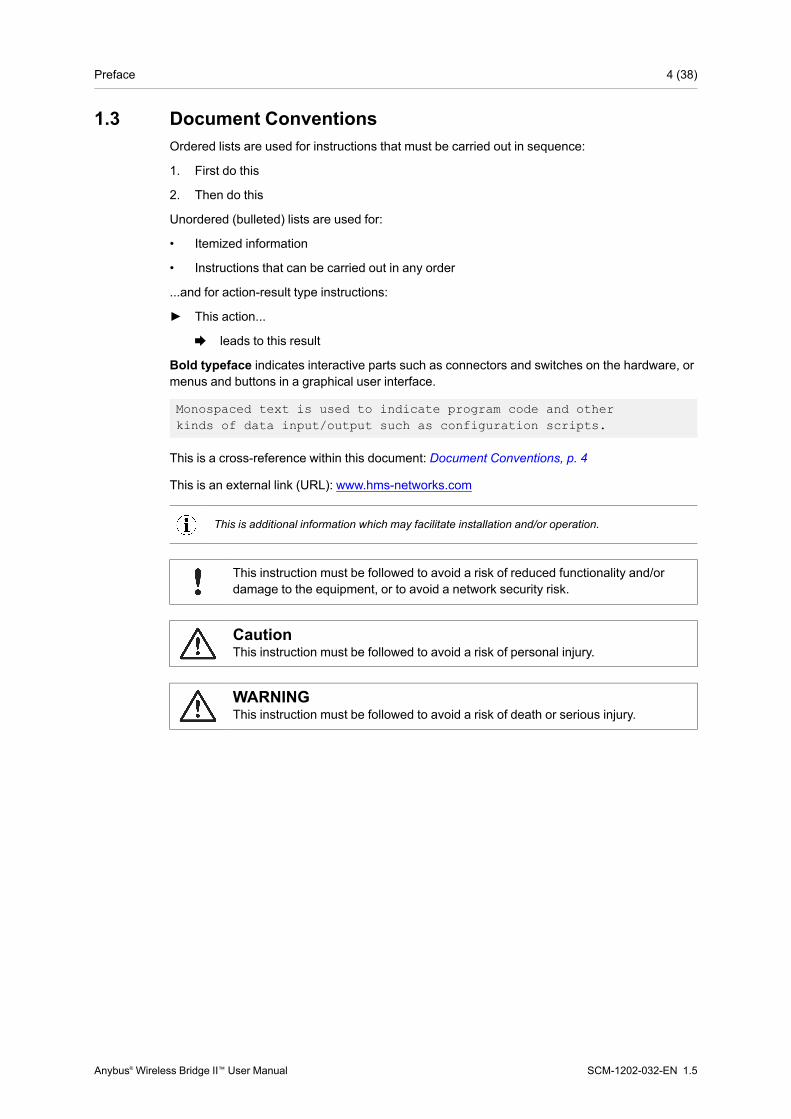
Bold typeface indicates interactive parts such as connectors and switches on the hardware, ormenus and buttons in a graphical user interface.
Monospaced text is used to indicate program code and otherkinds of data input/output such as configuration scripts.
This is a cross-reference within this document: Document Conventions, p. 4
This is an external link (URL): www.hms-networks.com
This is additional information which may facilitate installation and/or operation.
This instruction must be followed to avoid a risk of reduced functionality and/ordamage to the equipment, or to avoid a network security risk.
CautionThis instruction must be followed to avoid a risk of personal injury.
WARNINGThis instruction must be followed to avoid a risk of death or serious injury.
Anybus® Wireless Bridge II™ User Manual SCM-1202-032-EN 1.5
Description 5 (38)
2 Description2.1 Product Description
Anybus Wireless Bridge II provides wireless communication over WLAN and/or Bluetooth® towired networks.
Typical applications for Anybus Wireless Bridge II include:
• Adding wireless cloud connectivity to industrial devices
• Accessing devices from a laptop, smartphone or tablet
• Ethernet cable replacement between devices
Limitations:Bluetooth PAN (Personal Area Network) may not work with some devices due to differentimplementations of Bluetooth by different manufacturers.
WLAN 5 GHz cannot be used at the same time as WLAN 2.4 GHz or Bluetooth.
2.2 Bluetooth or WLAN?Use Bluetooth when...
• ...the wireless link has an Anybus Wireless Bridge II or Anybus Wireless Bolt at both ends.
• ...an interruption-free connection is more important than data throughput speed.
• ...interference robustness is important – e.g. in an industrial environment.
• ...a Profinet I/O cycle time or EtherNet/IP RPI of 64 ms or more is acceptable.
Use WLAN when...
• ...connecting to other types of wireless devices or a WLAN infrastructure.
• ...high data throughput speed is more important than connection reliability.
• ...large file transfers are expected.
• ...WLAN channel frequency planning is possible.
• ...a low Profinet I/O cycle time or EtherNet/IP RPI is desired.
Anybus® Wireless Bridge II™ User Manual SCM-1202-032-EN 1.5

Description 6 (38)
2.3 Model Name – Certification IdentifierThe model name is used to identify the product for various certifications. It consists of a modelprefix followed by two designators for the specific interface configuration and functionality.
Prefix AWB3 Anybus Wireless Bridge IIInterface configuration A
BInternal antenna (Closed Type), interfaces: Dual M12External antenna (Open Type), interfaces: Dual M12, RP-SMA
Functionality AB
Ethernet with digital inputEthernet w/o digital input
Example: AWB3AA = Anybus Wireless Bridge II with internal antenna, Ethernet networkingand digital input.
Anybus® Wireless Bridge II™ User Manual SCM-1202-032-EN 1.5
Installation 7 (38)
3 Installation3.1 Safety
CautionThis equipment emits RF energy in the ISM (Industrial, Scientific, Medical) band.Make sure that all medical devices used in proximity to this device meetappropriate susceptibility specifications for this type of RF energy.
This product is recommended for use in both industrial and domestic environments.For industrial environments it is mandatory to use the functional earth connectionto comply with immunity requirements. For domestic environments the functionalearth must be omitted if a shielded Ethernet cable is used, in order to meetemission requirements.
This product contains parts that can be damaged by electrostatic discharge (ESD).Use ESD prevention measures to avoid damage.
See also additional safety instructions in the included compliance information.
3.2 General InformationMake sure that you have all the necessary information about the capabilities and restrictions ofyour local network environment before installation.
The characteristics of the internal antenna should be considered when choosing the placementand orientation of the unit (unless an external antenna is used).
See Technical Data, p. 35 for details about the antenna characteristics.
For optimal reception, wireless devices require a zone between them clear of objects that couldotherwise obstruct or reflect the signal. A minimum distance of 50 cm between the devicesshould also be observed to avoid interference.
See alsoWireless Technology Basics, p. 34.
Anybus® Wireless Bridge II™ User Manual SCM-1202-032-EN 1.5
Installation 8 (38)
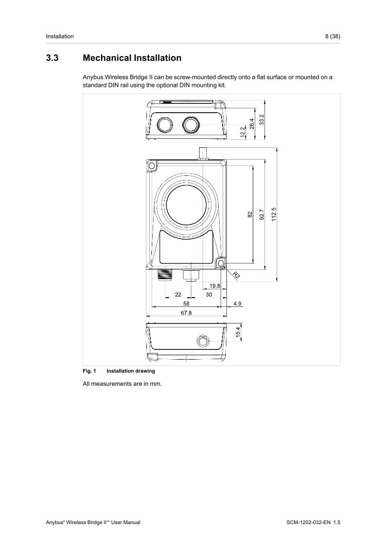
3.3 Mechanical Installation
Anybus Wireless Bridge II can be screw-mounted directly onto a flat surface or mounted on astandard DIN rail using the optional DIN mounting kit.
Fig. 1 Installation drawing
All measurements are in mm.
Anybus® Wireless Bridge II™ User Manual SCM-1202-032-EN 1.5

Installation 9 (38)
3.4 Connectors
Fig. 2 M12 connectors
Power Connector (A-coded male M12)Pin Function1 Power + (9–30 V)2 Digital Input Ground3 Power Ground4 Digital Input + (9–30 V)5 Functional Earth
Signal wiring for the digital input must be carried in the same cable as power andfunctional earth if wiring length exceeds 3 meters.
LAN Connector (D-coded female M12)Pin Function Color coding (T568B)1 Transmit + Orange/White2 Receive + Green/White3 Transmit - Orange4 Receive - Green
Anybus® Wireless Bridge II™ User Manual SCM-1202-032-EN 1.5

Installation 10 (38)
3.5 LED Indicators
Fig. 3 LED indicators
PWR Off No powerGreen Normal operation
WLAN
Off WLAN disabled or no powerBlue, blinking Access Point: No clients, awaiting connections
BlueAccess Point: Connected to at least one clientClient: Connected to access point
Blue, flickering WLAN data activity (when connected)Purple, blinking Client: Scanning for access pointsPurple Client: Connecting to a detected access pointRed Unrecoverable error
LANOff No Ethernet connectionYellow Ethernet link presentYellow, flickering Ethernet data activity (when connected)
BT
Off Bluetooth disabled or no powerBlue, blinking NAP: No clients, awaiting connections
Blue NAP: Connected to at least one PANU clientPANU: Connected to NAP
Blue, flickering Bluetooth data activity (when connected)Purple PANU: Trying to connect to NAPRed Unrecoverable error
RSSI (WLAN Client) / Link Quality (Bluetooth PANU)No connection
A RSSI/Link Quality < 25 %A B RSSI/Link Quality 25–50 %A B C RSSI/Link Quality 50–75 %A B C D RSSI/Link Quality > 75 %
Additional LED indications are used when the unit is in Recovery Mode.See Recovery Mode LED Indications, p. 25.
Anybus® Wireless Bridge II™ User Manual SCM-1202-032-EN 1.5

Configuration 11 (38)
4 Configuration4.1 General
Anybus Wireless Bridge II can be configured via the web interface or using one of the pre-configured Easy Configmodes.
Advanced configuration can be carried out by issuing AT (modem) commands through the webinterface or over a Telnet or RAW TCP connection to port 8080.
4.2 Easy Config1. Power on the unit and wait for the Link Quality LEDs to light up and go out again, then
immediately press and release the MODE button.
2. PressMODE repeatedly to cycle through the Easy Config modes until the desired mode isindicated by the A-B-C-D LEDs.
3. Within 20 seconds of step 2, press and holdMODE for 2 seconds. When the button isreleased the unit will restart in the selected mode.
Easy Config ModesMode Role Description LED2 — Reset configuration to factory defaults. B3 — Reset IP settings to factory defaults. A B4 Client Wait for automatic configuration. C5 WLAN AP Configure units in mode 4 as clients.
Restart as access point and connect clients.A C
6 Bluetooth NAP B C
7 WLAN AP Configure units in mode 4 as clients.Restart as access point and connect clients.Apply PROFINEToptimizations to all units.
A B C
8 Bluetooth NAP D
10 — Apply PROFINEToptimizations and restart. B D
Modes 5 – 8 will scan for units in mode 4. Detected units will be reconfigured as clients, and thescanning unit will restart as an access point. The clients will then restart and connect to theaccess point.
Modes 7 and 8 will additionally apply PROFINEToptimization to all the units. PROFINETmessages will then have priority over TCP/IP frames.
Mode Timeout• Modes 5 – 8 will time out after 120 seconds. Apply the mode again to repeat the scan.
• Mode 4 will listen for 120 seconds or until receiving a configuration.
The IP address of a client may be changed by the configuration from the accesspoint. Active browser sessions could therefore be lost.
Anybus® Wireless Bridge II™ User Manual SCM-1202-032-EN 1.5
Configuration 12 (38)
4.3 Web InterfaceThe web interface is accessed by pointing a web browser to the IP address of the WirelessBridge. The default IP address is 192.168.0.99. The computer accessing the web interfacemust be in the same IP subnet as the Wireless Bridge.
The web interface is designed for the current stable versions of Internet Explorer,Chrome, Firefox and Safari. Other browsers may not support the full functionalityof the web interface.
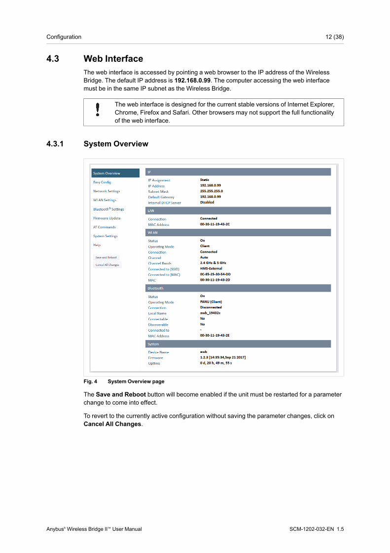
4.3.1 System Overview
Fig. 4 System Overview page
The Save and Reboot button will become enabled if the unit must be restarted for a parameterchange to come into effect.
To revert to the currently active configuration without saving the parameter changes, click onCancel All Changes.
Anybus® Wireless Bridge II™ User Manual SCM-1202-032-EN 1.5

Configuration 13 (38)
4.3.2 Easy Config
Fig. 5 Easy Config page
To activate an Easy Config mode, select it from the dropdown menu and click on Set.
Easy Config ModesMode Role Description LED2 — Reset configuration to factory defaults. B3 — Reset IP settings to factory defaults. A B4 Client Wait for automatic configuration. C5 WLAN AP Configure units in mode 4 as clients.
Restart as access point and connect clients.A C
6 Bluetooth NAP B C
7 WLAN AP Configure units in mode 4 as clients.Restart as access point and connect clients.Apply PROFINEToptimizations to all units.
A B C
8 Bluetooth NAP D
10 — Apply PROFINEToptimizations and restart. B D
Modes 5 – 8 will scan for units in mode 4. Detected units will be reconfigured as clients, and thescanning unit will restart as an access point. The clients will then restart and connect to theaccess point.
Modes 7 and 8 will additionally apply PROFINEToptimization to all the units. PROFINETmessages will then have priority over TCP/IP frames.
Mode Timeout• Modes 5 – 8 will time out after 120 seconds. Apply the mode again to repeat the scan.
• Mode 4 will listen for 120 seconds or until receiving a configuration.
The IP address of a client may be changed by the configuration from the accesspoint. Active browser sessions could therefore be lost.
Anybus® Wireless Bridge II™ User Manual SCM-1202-032-EN 1.5
Configuration 14 (38)
4.3.3 Network Settings
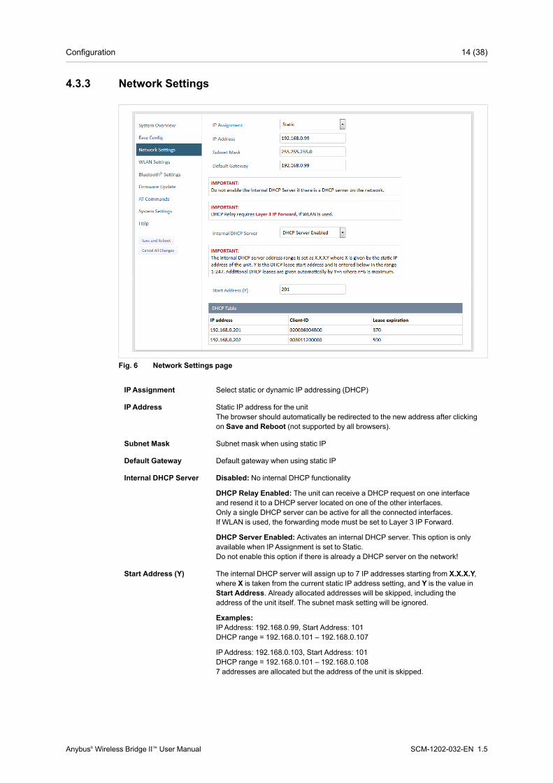
Fig. 6 Network Settings page
IPAssignment Select static or dynamic IP addressing (DHCP)
IPAddress Static IP address for the unitThe browser should automatically be redirected to the new address after clickingon Save and Reboot (not supported by all browsers).
Subnet Mask Subnet mask when using static IP
Default Gateway Default gateway when using static IP
Internal DHCP Server Disabled: No internal DHCP functionality
DHCP Relay Enabled: The unit can receive a DHCP request on one interfaceand resend it to a DHCP server located on one of the other interfaces.Only a single DHCP server can be active for all the connected interfaces.If WLAN is used, the forwarding mode must be set to Layer 3 IP Forward.
DHCP Server Enabled: Activates an internal DHCP server. This option is onlyavailable when IPAssignment is set to Static.Do not enable this option if there is already a DHCP server on the network!
Start Address (Y) The internal DHCP server will assign up to 7 IP addresses starting from X.X.X.Y,where X is taken from the current static IP address setting, and Y is the value inStart Address. Already allocated addresses will be skipped, including theaddress of the unit itself. The subnet mask setting will be ignored.
Examples:IP Address: 192.168.0.99, Start Address: 101DHCP range = 192.168.0.101 – 192.168.0.107
IPAddress: 192.168.0.103, Start Address: 101DHCP range = 192.168.0.101 – 192.168.0.1087 addresses are allocated but the address of the unit is skipped.
Anybus® Wireless Bridge II™ User Manual SCM-1202-032-EN 1.5
Configuration 15 (38)
4.3.4 WLAN Settings – Client Mode
Fig. 7 WLAN Settings – Client
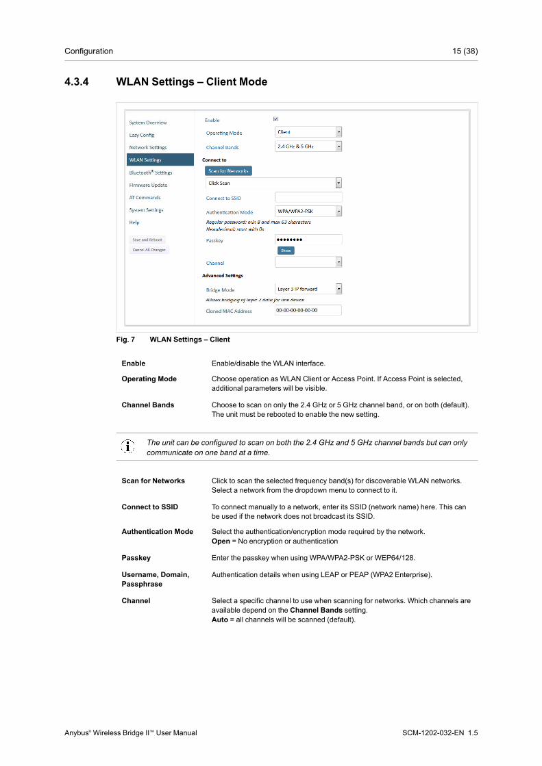
Enable Enable/disable the WLAN interface.
Operating Mode Choose operation as WLAN Client or Access Point. If Access Point is selected,additional parameters will be visible.
Channel Bands Choose to scan on only the 2.4 GHz or 5 GHz channel band, or on both (default).The unit must be rebooted to enable the new setting.
The unit can be configured to scan on both the 2.4 GHz and 5 GHz channel bands but can onlycommunicate on one band at a time.
Scan for Networks Click to scan the selected frequency band(s) for discoverable WLAN networks.Select a network from the dropdown menu to connect to it.
Connect to SSID To connect manually to a network, enter its SSID (network name) here. This canbe used if the network does not broadcast its SSID.
Authentication Mode Select the authentication/encryption mode required by the network.Open = No encryption or authentication
Passkey Enter the passkey when using WPA/WPA2-PSK or WEP64/128.
Username, Domain,Passphrase
Authentication details when using LEAP or PEAP (WPA2 Enterprise).
Channel Select a specific channel to use when scanning for networks. Which channels areavailable depend on the Channel Bands setting.Auto = all channels will be scanned (default).
Anybus® Wireless Bridge II™ User Manual SCM-1202-032-EN 1.5

Configuration 16 (38)
Fig. 8 WLAN Client – Advanced Settings
Advanced Settings
Bridge Mode Layer 2 tunnel = All layer 2 data will be bridged over WLAN.
Use when multiple devices on both sides of an Ethernet network bridge must beable to communicate via WLAN (many-to-many).
Only works between Anybus Wireless Bolt or Wireless Bridge II devices.
Layer 2 cloned MAC only = Layer 2 data from only a single MAC address(specified below) will be bridged over WLAN (many-to-one).
Layer 3 IP forward (default) = IP data from all devices will be bridged over WLAN.
This mode must be used when using the DHCP Relay function.
Cloned MAC Address The MAC address to use with Layer 2 cloned MAC only (see above).
Anybus® Wireless Bridge II™ User Manual SCM-1202-032-EN 1.5
Configuration 17 (38)
4.3.5 WLAN Settings – Access Point Mode
Fig. 9 WLAN Settings – Access Point
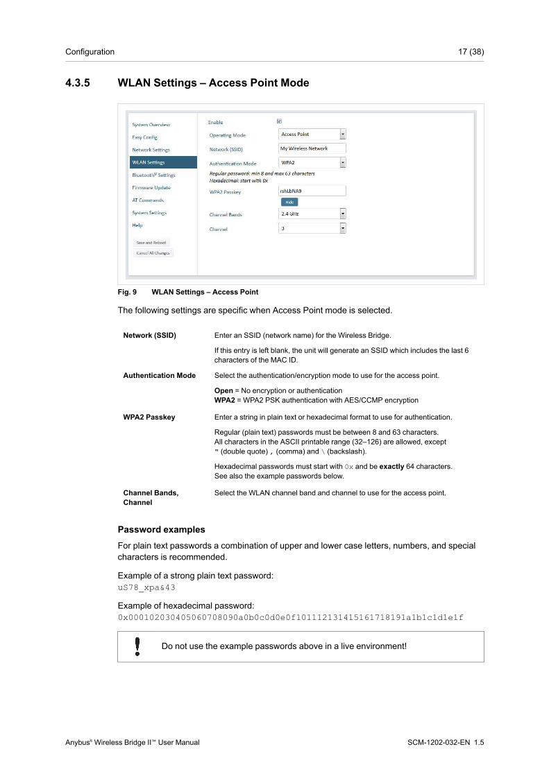
The following settings are specific when Access Point mode is selected.
Network (SSID) Enter an SSID (network name) for the Wireless Bridge.
If this entry is left blank, the unit will generate an SSID which includes the last 6characters of the MAC ID.
Authentication Mode Select the authentication/encryption mode to use for the access point.
Open = No encryption or authenticationWPA2 = WPA2 PSK authentication with AES/CCMP encryption
WPA2 Passkey Enter a string in plain text or hexadecimal format to use for authentication.
Regular (plain text) passwords must be between 8 and 63 characters.All characters in the ASCII printable range (32–126) are allowed, except" (double quote) , (comma) and \ (backslash).
Hexadecimal passwords must start with 0x and be exactly 64 characters.See also the example passwords below.
Channel Bands,Channel
Select the WLAN channel band and channel to use for the access point.
Password examplesFor plain text passwords a combination of upper and lower case letters, numbers, and specialcharacters is recommended.
Example of a strong plain text password:uS78_xpa&43
Example of hexadecimal password:0x000102030405060708090a0b0c0d0e0f101112131415161718191a1b1c1d1e1f
Do not use the example passwords above in a live environment!
Anybus® Wireless Bridge II™ User Manual SCM-1202-032-EN 1.5

Configuration 18 (38)
4.3.6 Bluetooth Settings – General
Fig. 10 Bluetooth Settings
Enable Enable/disable the Bluetooth interface.
Operating Mode PANU (Client) = The unit will operate as a Bluetooth PAN (Personal AreaNetwork) User device. It can connect to another single Bluetooth PANU device orto a Bluetooth Network Access Point.
NAP (Access Point) = The unit will operate as a Bluetooth Network Access Point.It can connect to up to 7 Bluetooth PANU devices.
Local Name Identifies the unit to other Bluetooth devices. If left blank, the unit will use a defaultname including the last 6 characters of the MAC ID.
Connectable Enable to make the unit accept connections initiated by other Bluetooth devices.
Discoverable Enable to make the unit visible to other Bluetooth devices.
Security Mode Disabled = No encryption or authentication.
PIN = Encrypted connection with PIN code security. This mode only worksbetween two units of this type and brand (not with third-party devices). PIN codesmust consist of 4 to 6 digits.
Just Works = Encrypted connection without PIN code.
Paired Devices Lists the currently connected Bluetooth devices.
Anybus® Wireless Bridge II™ User Manual SCM-1202-032-EN 1.5
Configuration 19 (38)
4.3.7 Bluetooth Settings – PANU Mode
Fig. 11 Bluetooth Settings – PANU
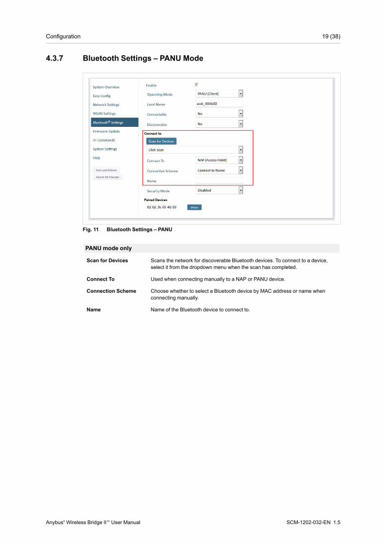
PANU mode only
Scan for Devices Scans the network for discoverable Bluetooth devices. To connect to a device,select it from the dropdown menu when the scan has completed.
Connect To Used when connecting manually to a NAP or PANU device.
Connection Scheme Choose whether to select a Bluetooth device by MAC address or name whenconnecting manually.
Name Name of the Bluetooth device to connect to.
Anybus® Wireless Bridge II™ User Manual SCM-1202-032-EN 1.5
Configuration 20 (38)
4.3.8 Bluetooth Settings – NAP Mode
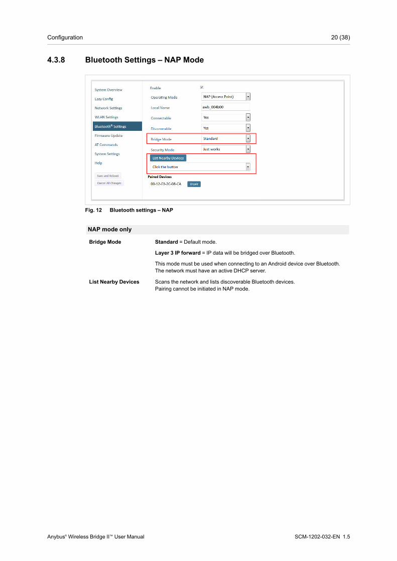
Fig. 12 Bluetooth settings – NAP
NAP mode only
Bridge Mode Standard = Default mode.
Layer 3 IP forward = IP data will be bridged over Bluetooth.
This mode must be used when connecting to an Android device over Bluetooth.The network must have an active DHCP server.
List Nearby Devices Scans the network and lists discoverable Bluetooth devices.Pairing cannot be initiated in NAP mode.
Anybus® Wireless Bridge II™ User Manual SCM-1202-032-EN 1.5

Configuration 21 (38)
4.3.9 Firmware Update
Fig. 13 Firmware Update
Click on Browse to select a firmware file, then click on Send to download it to the unit.
Both progress bars will turn green when the firmware update has been completed. The unit willthen reboot automatically.
Anybus® Wireless Bridge II™ User Manual SCM-1202-032-EN 1.5
Configuration 22 (38)
4.3.10 AT Commands
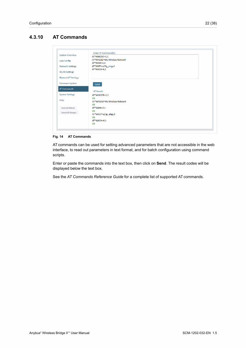
Fig. 14 AT Commands
ATcommands can be used for setting advanced parameters that are not accessible in the webinterface, to read out parameters in text format, and for batch configuration using commandscripts.
Enter or paste the commands into the text box, then click on Send. The result codes will bedisplayed below the text box.
See the AT Commands Reference Guide for a complete list of supported ATcommands.
Anybus® Wireless Bridge II™ User Manual SCM-1202-032-EN 1.5
Configuration 23 (38)
4.3.11 System Settings
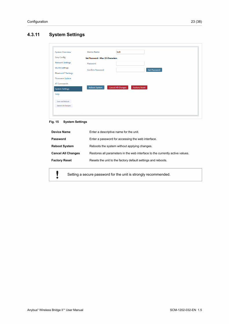
Fig. 15 System Settings
Device Name Enter a descriptive name for the unit.
Password Enter a password for accessing the web interface.
Reboot System Reboots the system without applying changes.
Cancel All Changes Restores all parameters in the web interface to the currently active values.
Factory Reset Resets the unit to the factory default settings and reboots.
Setting a secure password for the unit is strongly recommended.
Anybus® Wireless Bridge II™ User Manual SCM-1202-032-EN 1.5

Configuration 24 (38)
4.4 Factory RestoreAny one of these actions will restore the factory default settings:
• Holding MODE pressed for >10 seconds and then releasing it
• Executing Easy Config Mode 2
• Clicking on Factory Restore on the System Settings page
• Issuing the ATcommand AT&F and then restarting the unit
Default Network SettingsIPAssignment StaticIPAddress 192.168.0.99Subnet Mask 255.255.255.0Default Gateway 192.168.0.99
Default WLAN SettingsOperating Mode ClientChannel Bands 2.4 GHz & 5 GHzAuthentication Mode WPA/WPA2–PSKChannel AutoBridge Mode Layer 3 IP forward
Default Bluetooth SettingsOperating Mode PANU (Client)Local Name [generated from MAC address]Security Mode Just works
Default System SettingsPassword [empty]
Setting a secure password for the unit is strongly recommended.
Anybus® Wireless Bridge II™ User Manual SCM-1202-032-EN 1.5
Configuration 25 (38)
4.5 MODE Button
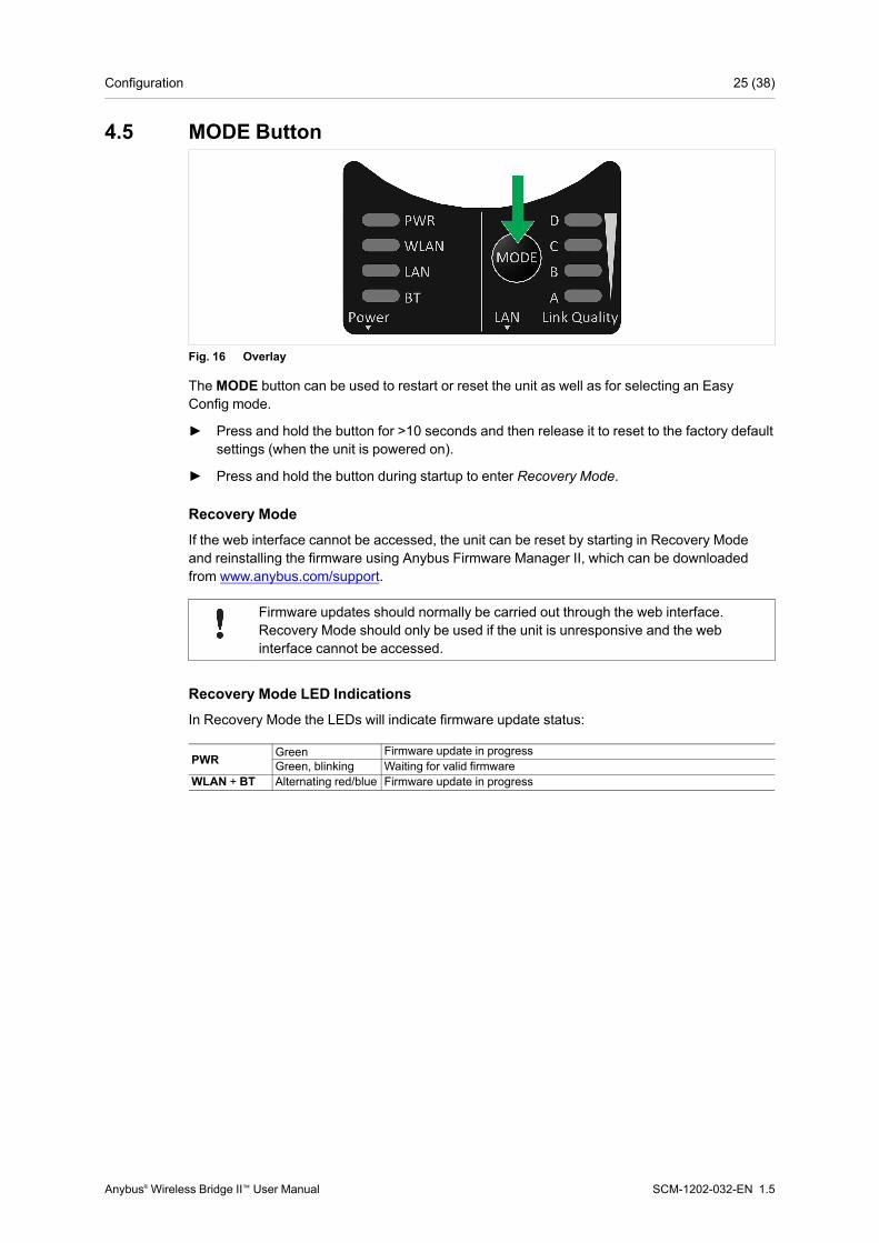
Fig. 16 Overlay
TheMODE button can be used to restart or reset the unit as well as for selecting an EasyConfig mode.
► Press and hold the button for >10 seconds and then release it to reset to the factory defaultsettings (when the unit is powered on).
► Press and hold the button during startup to enter Recovery Mode.
Recovery ModeIf the web interface cannot be accessed, the unit can be reset by starting in Recovery Modeand reinstalling the firmware using Anybus Firmware Manager II, which can be downloadedfrom www.anybus.com/support.
Firmware updates should normally be carried out through the web interface.Recovery Mode should only be used if the unit is unresponsive and the webinterface cannot be accessed.
Recovery Mode LED IndicationsIn Recovery Mode the LEDs will indicate firmware update status:
PWR Green Firmware update in progressGreen, blinking Waiting for valid firmware
WLAN + BT Alternating red/blue Firmware update in progress
Anybus® Wireless Bridge II™ User Manual SCM-1202-032-EN 1.5

This page intentionally left blank
Appendix A: Configuration Examples 27 (38)
A Configuration ExamplesA.1 Ethernet Bridge via WLAN or Bluetooth®
Configuration with Easy Config
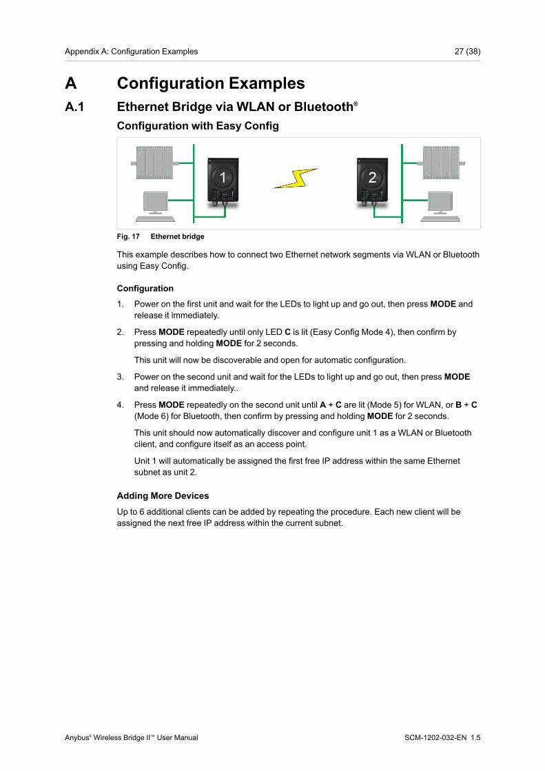
Fig. 17 Ethernet bridge
This example describes how to connect two Ethernet network segments via WLAN or Bluetoothusing Easy Config.
Configuration
1. Power on the first unit and wait for the LEDs to light up and go out, then press MODE andrelease it immediately.
2. PressMODE repeatedly until only LED C is lit (Easy Config Mode 4), then confirm bypressing and holding MODE for 2 seconds.
This unit will now be discoverable and open for automatic configuration.
3. Power on the second unit and wait for the LEDs to light up and go out, then press MODEand release it immediately..
4. PressMODE repeatedly on the second unit until A + C are lit (Mode 5) for WLAN, or B + C(Mode 6) for Bluetooth, then confirm by pressing and holding MODE for 2 seconds.
This unit should now automatically discover and configure unit 1 as a WLAN or Bluetoothclient, and configure itself as an access point.
Unit 1 will automatically be assigned the first free IP address within the same Ethernetsubnet as unit 2.
Adding More DevicesUp to 6 additional clients can be added by repeating the procedure. Each new client will beassigned the next free IP address within the current subnet.
Anybus® Wireless Bridge II™ User Manual SCM-1202-032-EN 1.5

Appendix A: Configuration Examples 28 (38)
A.2 PROFINET networking via Bluetooth®
Configuration with Easy Config
Fig. 18 PROFINETwireless network
This example describes how to connect a PROFINET IO device and a PROFINET PLC overBluetooth using two Wireless Bridges and Easy Config.
The Wireless Bridges will be configured with PROFINEToptimization, which means thatPROFINET messages will have priority over TCP/IP frames.
See the respective documentation for the IO device and PLC on how to configure them forPROFINETcommunication.
Configuration
1. Reset both Wireless Bridges to the factory default settings.
2. Connect Wireless Bridge 1 to the IO device and Wireless Bridge 2 to the PLC.
3. Set Wireless Bridge 1 to Easy ConfigMode 4.
This unit will now be discoverable and open for automatic configuration.
4. Set Wireless Bridge 2 to Easy ConfigMode 8
This unit should now automatically discover and configure unit 1 as a Bluetooth client, andconfigure itself as an access point. Both units will be optimized for PROFINET.
The IO device should now be able to communicate with the PLC as if using a wired connection.
Adding More DevicesUp to 6 additional clients can be added by repeating the procedure. Each new client will beassigned the next free IP address within the current subnet.
The IO cycle update time for each IO device must be set to ≥ 64 ms.
Anybus® Wireless Bridge II™ User Manual SCM-1202-032-EN 1.5
Appendix A: Configuration Examples 29 (38)
A.3 EtherNet/IP™ Networking via Bluetooth®
Configuration with Easy Config
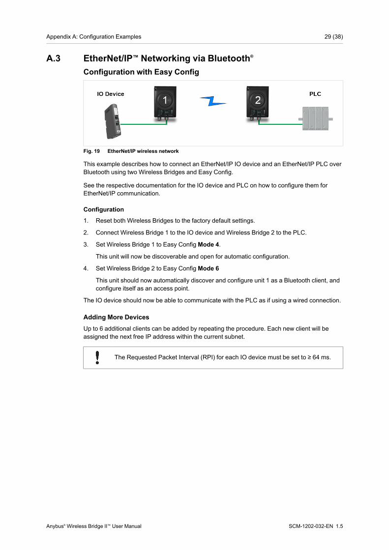
Fig. 19 EtherNet/IP wireless network
This example describes how to connect an EtherNet/IP IO device and an EtherNet/IP PLC overBluetooth using two Wireless Bridges and Easy Config.
See the respective documentation for the IO device and PLC on how to configure them forEtherNet/IP communication.
Configuration
1. Reset both Wireless Bridges to the factory default settings.
2. Connect Wireless Bridge 1 to the IO device and Wireless Bridge 2 to the PLC.
3. Set Wireless Bridge 1 to Easy ConfigMode 4.
This unit will now be discoverable and open for automatic configuration.
4. Set Wireless Bridge 2 to Easy ConfigMode 6
This unit should now automatically discover and configure unit 1 as a Bluetooth client, andconfigure itself as an access point.
The IO device should now be able to communicate with the PLC as if using a wired connection.
Adding More DevicesUp to 6 additional clients can be added by repeating the procedure. Each new client will beassigned the next free IP address within the current subnet.
The Requested Packet Interval (RPI) for each IO device must be set to ≥ 64 ms.
Anybus® Wireless Bridge II™ User Manual SCM-1202-032-EN 1.5
Appendix A: Configuration Examples 30 (38)
A.4 Ethernet network to existing WLAN
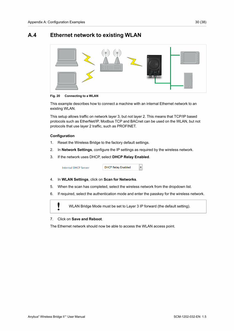
Fig. 20 Connecting to a WLAN
This example describes how to connect a machine with an internal Ethernet network to anexisting WLAN.
This setup allows traffic on network layer 3, but not layer 2. This means that TCP/IP basedprotocols such as EtherNet/IP, Modbus TCP and BACnet can be used on the WLAN, but notprotocols that use layer 2 traffic, such as PROFINET.
Configuration
1. Reset the Wireless Bridge to the factory default settings.
2. In Network Settings, configure the IP settings as required by the wireless network.
3. If the network uses DHCP, select DHCP Relay Enabled.
4. InWLAN Settings, click on Scan for Networks.
5. When the scan has completed, select the wireless network from the dropdown list.
6. If required, select the authentication mode and enter the passkey for the wireless network.
WLAN Bridge Mode must be set to Layer 3 IP forward (the default setting).
7. Click on Save and Reboot.
The Ethernet network should now be able to access the WLAN access point.
Anybus® Wireless Bridge II™ User Manual SCM-1202-032-EN 1.5
Appendix A: Configuration Examples 31 (38)
A.5 Adding single Ethernet node to WLAN
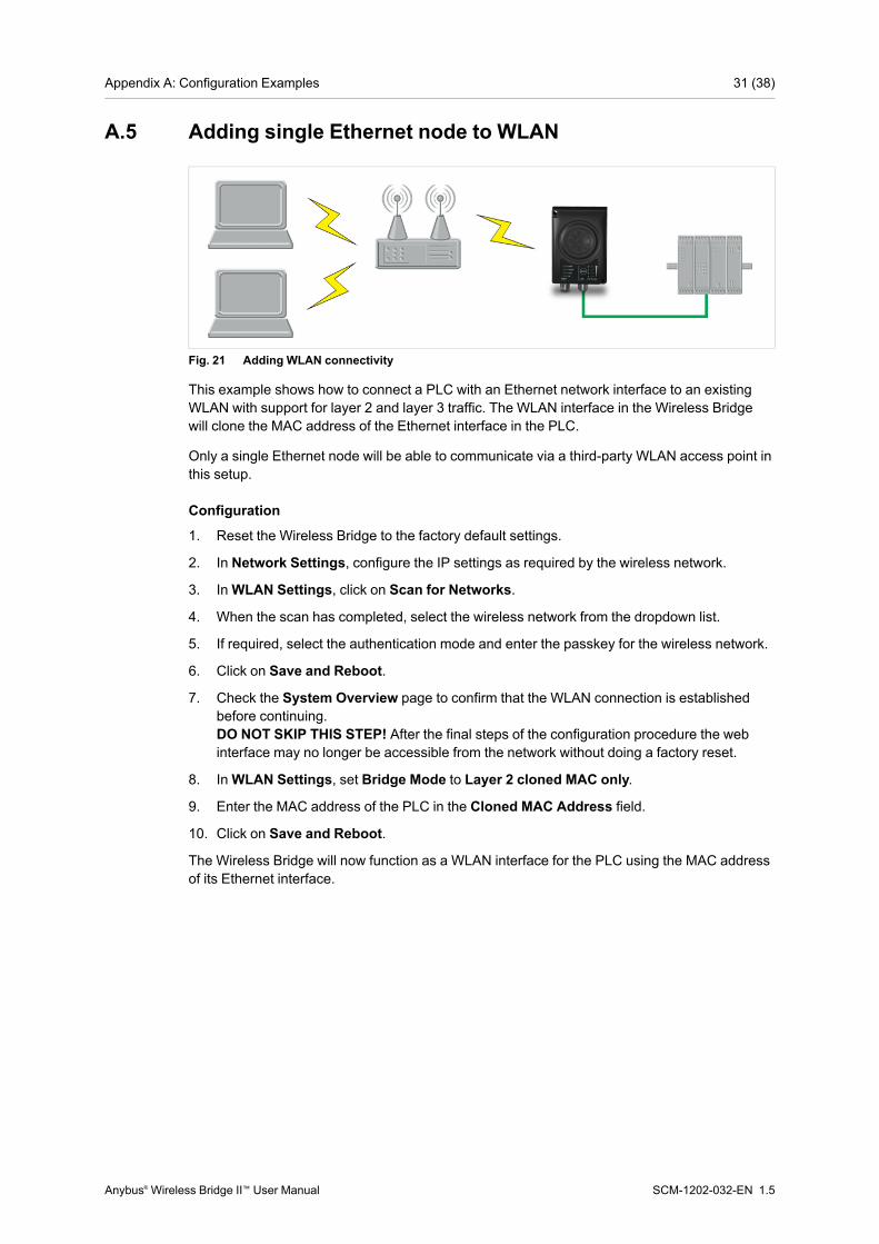
Fig. 21 Adding WLAN connectivity
This example shows how to connect a PLC with an Ethernet network interface to an existingWLAN with support for layer 2 and layer 3 traffic. The WLAN interface in the Wireless Bridgewill clone the MAC address of the Ethernet interface in the PLC.
Only a single Ethernet node will be able to communicate via a third-party WLAN access point inthis setup.
Configuration
1. Reset the Wireless Bridge to the factory default settings.
2. In Network Settings, configure the IP settings as required by the wireless network.
3. InWLAN Settings, click on Scan for Networks.
4. When the scan has completed, select the wireless network from the dropdown list.
5. If required, select the authentication mode and enter the passkey for the wireless network.
6. Click on Save and Reboot.
7. Check the System Overview page to confirm that the WLAN connection is establishedbefore continuing.DO NOT SKIP THIS STEP! After the final steps of the configuration procedure the webinterface may no longer be accessible from the network without doing a factory reset.
8. InWLAN Settings, set Bridge Mode to Layer 2 cloned MAC only.
9. Enter the MAC address of the PLC in the Cloned MAC Address field.
10. Click on Save and Reboot.
The Wireless Bridge will now function as a WLAN interface for the PLC using the MAC addressof its Ethernet interface.
Anybus® Wireless Bridge II™ User Manual SCM-1202-032-EN 1.5

Appendix A: Configuration Examples 32 (38)
A.6 Accessing PLC via WLAN from Handheld Device
Fig. 22 Accessing a PLC from a handheld device using WLAN
This example describes how to use a Wireless Bridge to access the web interface of a PLC ona wired network from a tablet or smartphone which uses DHCP. The Wireless Bridge willfunction as a WLAN access point.
Please refer to the documentation for the handheld device and PLC on how to configure theirrespective network settings.
Configuration
1. Reset the Wireless Bridge to the factory default settings.
2. In Network Settings, configure the IP settings as required.
a. If the wired network uses DHCP, select DHCP Relay Enabled. The DHCP server onthe network will now be able to allocate an IP address to the handheld device.
b. If the wired network uses static IP, select DHCP Server Enabled and set a StartAddress for DHCP addressing. Make sure that the address range does not containany existing addresses on the network.
The Wireless Bridge will now function as a DHCP server and allocate an IP address tothe handheld device over WLAN.
Do not enable the internal DHCP Server if there is already a DHCP server on thenetwork, as this may cause IP address conflicts.
Anybus® Wireless Bridge II™ User Manual SCM-1202-032-EN 1.5
Appendix A: Configuration Examples 33 (38)
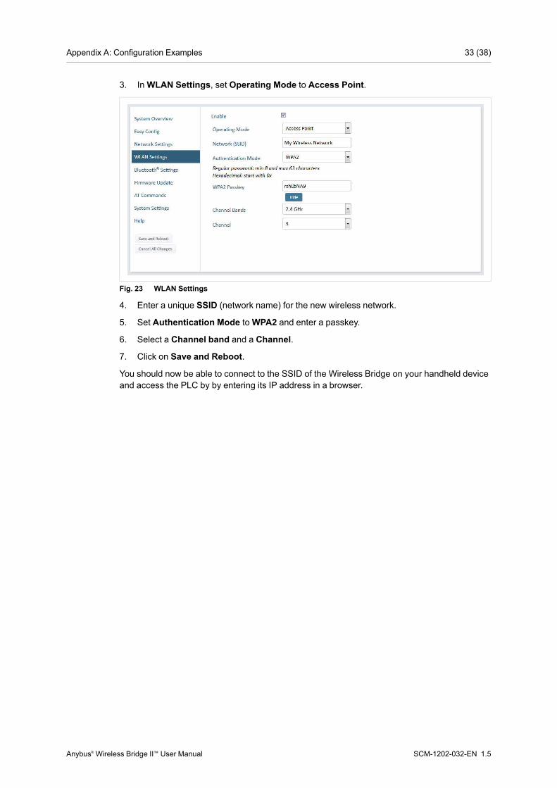
3. InWLAN Settings, set Operating Mode to Access Point.
Fig. 23 WLAN Settings
4. Enter a unique SSID (network name) for the new wireless network.
5. Set Authentication Mode toWPA2 and enter a passkey.
6. Select a Channel band and a Channel.
7. Click on Save and Reboot.
You should now be able to connect to the SSID of the Wireless Bridge on your handheld deviceand access the PLC by by entering its IP address in a browser.
Anybus® Wireless Bridge II™ User Manual SCM-1202-032-EN 1.5

Appendix B: Wireless Technology Basics 34 (38)
B Wireless Technology BasicsWireless technology is based on the propagation and reception of electromagnetic waves.These waves respond in different ways in terms of propagation, dispersion, diffraction andreflection depending on their frequency and the medium in which they are travelling.
To enable communication there should optimally be an unobstructed line of sight between theantennas of the devices. However, the so called Fresnel Zones should also be kept clear fromobstacles, as radio waves reflected from objects within these zones may reach the receiver outof phase, reducing the strength of the original signal (also known as phase cancelling).
Fresnel zones can be thought of as ellipsoid three-dimensional shapes between two wirelessdevices. The size and shape of the zones depend on the distance between the devices and onthe signal wave length. As a rule of thumb, at least 60 % of the first (innermost) Fresnel zonemust be free of obstacles to maintain good reception.
Fig. 24 Fresnel zones
Area to keep clear of obstacles (first Fresnel zone)
Distance (d)Fresnel zone radius (r)
2.4 GHz (WLAN or Bluetooth) 5 GHz (WLAN)100 m 1.7 m 1.2 m200 m 2.5 m 1.7 m300 m 3.0 m 2.1 m400 m 3.5 m 2.4 m
The wireless signal may be adequate even if there are obstacles within the Fresnel zones, as italways depends on the number and size of the obstacles and where they are located. This isespecially true indoors, where reflections on metal objects may actually help the propagation ofradio waves. To reduce interference and phase cancelling, the range may also need to belimited by reducing the transmission power. For determining the optimal configuration andplacement of wireless devices it is therefore recommended to use a wireless signal analysistool.
Anybus® Wireless Bridge II™ User Manual SCM-1202-032-EN 1.5
Appendix C: Technical Data 35 (38)
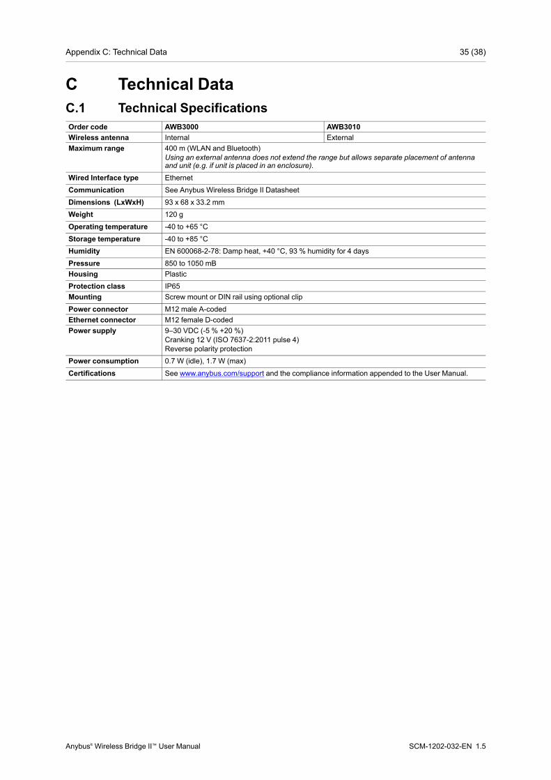
C Technical DataC.1 Technical SpecificationsOrder code AWB3000 AWB3010Wireless antenna Internal ExternalMaximum range 400 m (WLAN and Bluetooth)
Using an external antenna does not extend the range but allows separate placement of antennaand unit (e.g. if unit is placed in an enclosure).
Wired Interface type EthernetCommunication See Anybus Wireless Bridge II DatasheetDimensions (LxWxH) 93 x 68 x 33.2 mmWeight 120 g
Operating temperature -40 to +65 °CStorage temperature -40 to +85 °CHumidity EN 600068-2-78: Damp heat, +40 °C, 93 % humidity for 4 daysPressure 850 to 1050 mBHousing PlasticProtection class IP65Mounting Screw mount or DIN rail using optional clipPower connector M12 male A-codedEthernet connector M12 female D-codedPower supply 9–30 VDC (-5 % +20 %)
Cranking 12 V (ISO 7637-2:2011 pulse 4)Reverse polarity protection
Power consumption 0.7 W (idle), 1.7 W (max)
Certifications See www.anybus.com/support and the compliance information appended to the User Manual.
Anybus® Wireless Bridge II™ User Manual SCM-1202-032-EN 1.5

Appendix C: Technical Data 36 (38)
C.2 Internal Antenna CharacteristicsAnybus Wireless Bridge II has 3 independent quarter wave monopole antennas. The followingradiation diagrams and tables show the characteristics of the different antennas as measuredunder laboratory test conditions. The diagrams can be used as a general guide for finding theoptimal placement and orientation of the units.
The diagrams use a color spectrum from violet to red to indicate signal gain. The closer to thered end of the spectrum, the stronger the signal.
2.4 GHz Section of Dual Band Antenna
Fig. 25 2.4 GHz antenna gain and directivity in horizontal and vertical planes
Test Antenna Section F Avg Gain Peak Gain Dir Comment# Dual band 2.4GHz MHz dBi % dBi dB In Plastic Box148 2400 -2.78 52.7 +1.61 4.3149 2440 -2.24 60.5 +1.80 3.9150 2485 -1.89 64.7 +2.00 3.9
5 GHz Section of Dual Band Antenna
Fig. 26 5 GHz antenna gain and directivity in horizontal and vertical planes
Test Antenna Section F Avg Gain Peak Gain Dir Comment# Dual band 5GHz MHz dBi % dBi dB In Plastic Box151 5150 -4.80 33.1 -2.48 2.3152 5250 -3.42 45.5 -0.75 2.7153 5400 -3.13 48.6 -0.14 3.0154 5600 -1.96 63.7 +0.48 2.4
Anybus® Wireless Bridge II™ User Manual SCM-1202-032-EN 1.5
Appendix C: Technical Data 37 (38)
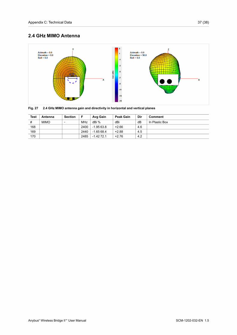
2.4 GHz MIMO Antenna
Fig. 27 2.4 GHz MIMO antenna gain and directivity in horizontal and vertical planes
Test Antenna Section F Avg Gain Peak Gain Dir Comment# MIMO - MHz dBi % dBi dB In Plastic Box168 2400 -1.95 63.8 +2.66 4.6169 2440 -1.65 68.4 +2.88 4.5170 2485 -1.42 72.1 +2.76 4.2
Anybus® Wireless Bridge II™ User Manual SCM-1202-032-EN 1.5

last page
© 2018 HMS Industrial Networks ABBox 4126300 04 Halmstad, Sweden
[email protected] SCM-1202-032-EN 1.5.7275 / 2018-02-02


