56
Siemens Energy & Automation, Inc. Installation and Service Instruction SD39IFI-1 Rev. 1 March 2001 APACS+ ® /QUADLOG ® IOBUS Fiber-optic Interface (IFI) Installation and Service Instruction

Siemens Energy & Automation, Inc.
Installation and Service Instruction
SD39IFI-1 Rev. 1 March 2001
APACS+®/QUADLOG®
IOBUS Fiber-optic Interface (IFI)
Installation and Service Instruction


SD39IFI-1 Contents
March 2001 i
Table of Contents Section Title Page 1.0 Introduction...............................................................................................................1-1 1.1 Product Description ..................................................................................................1-1 1.2 Product Support........................................................................................................1-8 1.3 International Standards Organization (ISO) Symbols .............................................1-11 1.4 Related Literature ...................................................................................................1-12 2.0 Installation .................................................................................................................2-1 2.1 Pre-Installation Preparation.......................................................................................2-1 2.2 Environmental Considerations ..................................................................................2-2 2.3 Equipment Delivery and Handling............................................................................2-3 2.3.1 Predelivery Test .................................................................................................2-3 2.3.2 Factory Shipment ...............................................................................................2-3 2.3.3 Receipt of Shipment ...........................................................................................2-4 2.3.4 Return of Shipment ............................................................................................2-4 2.3.5 Equipment Handling ..........................................................................................2-5 2.3.6 Equipment Storage .............................................................................................2-5 2.4 Fiber-optic Cable Installation....................................................................................2-5 2.4.1 Site Survey.........................................................................................................2-5 2.4.2 Fiber-optic Cable Routing Design.......................................................................2-6 2.4.3 Cable Pulling and Installation.............................................................................2-6 2.5 IFI Mechanical Installation .......................................................................................2-8 2.5.1 IFI Assembly Installation ...................................................................................2-8 2.5.1.1 Electrical Interface Module Installation ..........................................................2-8 2.5.1.2 Optical Interface Module Installation..............................................................2-9 2.5.1.3 Hand Shake Module Installation .....................................................................2-9 2.6 Electrical Installation ..............................................................................................2-10 2.6.1 IOBUS IN/OUT-to-IFI Cable Connection ........................................................2-10 2.6.2 Jumper Settings................................................................................................2-13 2.6.2.1 Optical Interface Jumper Setting...................................................................2-13 2.6.2.2 Hand Shake Jumper Setting ..........................................................................2-14 3.0 Maintenance...............................................................................................................3-1 3.1 Tool Requirements ...................................................................................................3-1 3.2 Preventive Maintenance............................................................................................3-1 3.2.1 Visual Inspection................................................................................................3-1 3.2.2 Cleaning ............................................................................................................3-1 3.3 Troubleshooting .......................................................................................................3-1 3.3.1 IFI Troubleshooting ............................................................................................3-2 3.3.2 IFI-to-IOBUS Cable Continuity Check................................................................3-4
Contents SD39IFI-1
ii March 2001
Table Of Contents (Continued)
Section Title Page 3.4 Module Replacement................................................................................................3-5 3.4.1 EIM (Electrical Interface Module) Removal/Replacement ..................................3-5 3.4.2 OIM (Optical Interface Module) Removal/Replacement .....................................3-5 3.4.3 HSM (Hand Shake Module)Removal/Replacement ............................................3-6 3.5 Spare and Replacement Parts ....................................................................................3-7 3.6 Maintenance Records................................................................................................3-7 4.0 Circuit Description ....................................................................................................4-1 4.1 IFI Components........................................................................................................4-1 4.2 IFI Operation............................................................................................................4-1 4.2.1 Optical Transmitter ............................................................................................4-2 4.2.2 Optical Receiver.................................................................................................4-3 4.2.3 Repeater Operation.............................................................................................4-3 4.3 Basic Fiber-optics .....................................................................................................4-3 5.0 IFI Components and IOBUS Cables .........................................................................5-1 5.1 IFI Components........................................................................................................5-1 5.2 IFI IOBUS Cables ....................................................................................................5-1 6.0 Specifications .............................................................................................................6-1 6.1 IFI Component Specifications...................................................................................6-1 6.2 Environmental Specifications ...................................................................................6-3 6.3 Electrical Classification.............................................................................................6-3 6.3.1 Approvals ..........................................................................................................6-3 6.3.2 CSA Hazardous Location Precautions ................................................................6-4 6.3.3 Special Conditions for Safe Use .........................................................................6-5 Declaration of Conformity Warranty

SD39IFI-1 Contents
March 2001 iii
List of Figures Figure Title Page Figure 1-1 Basic APACS+ IOBUS Fiber-optic Interface (IFI) Assembly..............................................1-2 Figure 1-2 Basic QUADLOG IFI Assembly.........................................................................................1-3 Figure 1-3 Point-to-Point Fiber-optic Topology Using Basic APACS+ IFI Assemblies ........................1-4 Figure 1-4 Point-to-Point Fiber-optic Topology Using Basic QUADLOG IFI Assemblies ....................1-5 Figure 1-5 Daisy-chain Fiber-optic Topology Using Basic APACS+ IFI Assemblies...........................1-6 Figure 1-6 Star Fiber-optic Topology Using Basic APACS+ IFI and Optional APACS+ Star Assemblies ....................................................................................1-7 Figure 2–1 Module Fully Mounted onto DIN Rail................................................................................2-9 Figure 2–2 IOBUS-to-IFI and IFI-to-IOBUS Cables ..........................................................................2-12 Figure 2–3 Setting Star Address Jumper Positions..............................................................................2-14 Figure 3-1 IFI-to-IOBUS Cable Wiring Diagram .................................................................................3-4 Figure 4-1 IFI Block Diagram..............................................................................................................4-2 Figure 4-2 Graded and Step Index Multimode Fibers ...........................................................................4-5 Figure 4-3 Numerical Aperture ............................................................................................................4-6
List of Tables
Table Title Page Table 1–1 TIC Contact Information .................................................................................................1-10 Table 1–2 ISO/IEC Symbols............................................................................................................1-11 Table 2-1 IOBUS-to-IFI Cable Connection Data ..............................................................................2-11 Table 2-2 Fiber-optic Cable Connection...........................................................................................2-13 Table 3-1 Status LED Indications.......................................................................................................3-2 Table 5-1 IFI Components .................................................................................................................5-1 Table 5-2 IFI IOBUS Cables..............................................................................................................5-1 Table 6–1 IFI Specifications ...............................................................................................................6-1 Table 6-2 IFI Environmental Specifications .......................................................................................6-3 Table 6-3 Agency Approvals for IFI ..................................................................................................6-4

Contents SD39IFI-1
iv March 2001
Siemens Energy & Automation, Inc. assumes no liability for errors or omissions in this document or for the application and use of information included in this document. The information herein is subject to change without notice.
Procedures included in this document have been reviewed for compliance with applicable approval agency requirements and are considered sound practice. Neither Siemens Energy & Automation, Inc. nor these agencies are responsible for repairs made by the user.
APACS+, QUADLOG, ProcessSuite, and 4-mation are trademarks of Siemens Energy & Automation, Inc. All other trademarks are the property of their respective owners.
© Copyright 2001 Siemens Energy & Automation, Inc. All rights reserved.
SD39IFI-1 Introduction
March 2001 1-1
1.0 Introduction This document provides installation and service information for the IOBUS Fiber-optic Interface (IFI), which is compatible for both APACS+ and QUADLOG hardware: This document is divided into six major sections: • Section 1, Introduction - Provides product description and related literature sections. • Section 2, Installation - Describes mechanical and electrical installation. • Section 3, Maintenance - Provides preventive maintenance, troubleshooting, module replacement
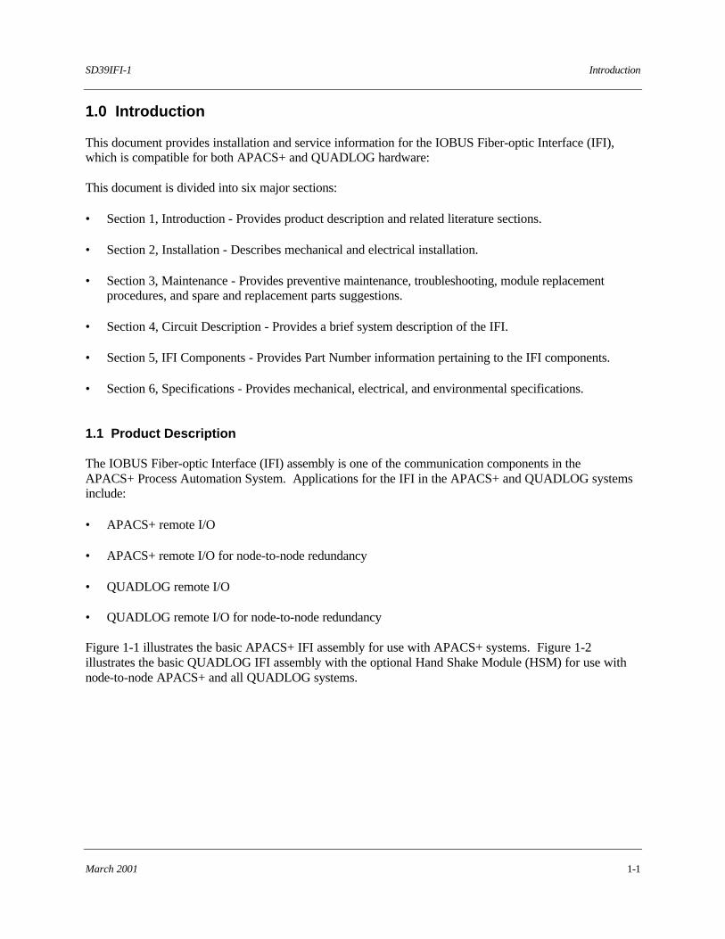
procedures, and spare and replacement parts suggestions. • Section 4, Circuit Description - Provides a brief system description of the IFI. • Section 5, IFI Components - Provides Part Number information pertaining to the IFI components. • Section 6, Specifications - Provides mechanical, electrical, and environmental specifications. 1.1 Product Description The IOBUS Fiber-optic Interface (IFI) assembly is one of the communication components in the APACS+ Process Automation System. Applications for the IFI in the APACS+ and QUADLOG systems include: • APACS+ remote I/O • APACS+ remote I/O for node-to-node redundancy • QUADLOG remote I/O • QUADLOG remote I/O for node-to-node redundancy Figure 1-1 illustrates the basic APACS+ IFI assembly for use with APACS+ systems. Figure 1-2 illustrates the basic QUADLOG IFI assembly with the optional Hand Shake Module (HSM) for use with node-to-node APACS+ and all QUADLOG systems.
Introduction SD39IFI-1
1-2 March 2001
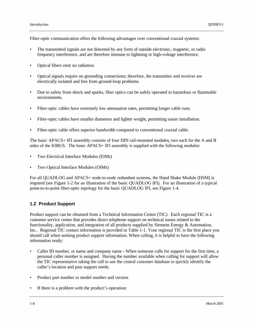
Figure 1-1 Basic APACS+ IOBUS Fiber-optic Interface (IFI) Assembly
A
A
EIM
PWR
COM
View A-A
IOBUS "1" O/WIOBUS "2" W/O
SHIELDN/C
B 24VDC -B 24VDC +A 24VDC -A 24VDC +

SD39IFI-1 Introduction
March 2001 1-3
Figure 1-2 Basic QUADLOG IFI Assembly
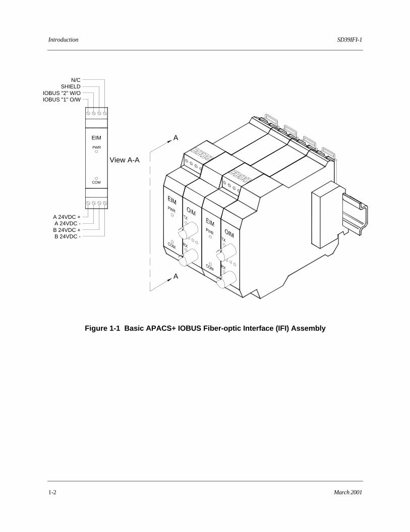
The IFI permits the APACS+ IOBUS to be extended from a local module rack (MODULRAC, SIXRAC, 4-slot Remote I/O Rack, or UNIRAC) to remote I/O module racks. Each fiber-optic segment can be up to 7,500 feet (2.3 km) in length. The IFI provides the additional benefit of permitting a star-type arrangement for non-redundant and peer-to-peer redundant APACS+ and QUADLOG systems by extending the IOBUS to as many as three separate remote I/O locations. The IFI repeats both the A and B sides of the IOBUS. The basic QUADLOG IFI can be used for all QUADLOG and node-to-node redundant APACS+ systems. Refer to Figures 1-3, 1-4, 1-5, and 1-6 for typical fiber-optic IOBUS topologies.
B
A
A
B
EIM
PWR
COM
View A-A
A 24VDC +A 24VDC -B 24VDC +B 24VDC -
N/CSHIELD
IOBUS "2" W/OIOBUS "1" O/W
HSM
TX
RX
LOC REM
MASTER OK W/GOK (IN/OUT) G/W
MASTER ENABLE RET W/BMASTER ENABLE B/W
View B-B
I/O A
I/O B
LEGENDW/G= White wire with Green stripeG/W= Green wire with White stripeW/B= White wire with Blue stripeB/W= Blue wire with White stripe

Introduction SD39IFI-1
1-4 March 2001
Figure 1-3 Point-to-Point Fiber-optic Topology Using Basic APACS+ IFI Assemblies
MODULRAC 1A
A B
B
A
A B
B
IOBUS Out-to-IFI Cables
A
B
A B
A
B
A B
IFI-to-IOBUS Cables
MODULRAC 3A
B
A B
A
B
A B
A
B
B
A
B
B
A
A
IOBUS Terminate
IOBUS Terminate
Standard IOBUS Cables
Local IFI
IOBUS In
MODULRAC 4
SIDE A SIDE B
Remote IFI
MODULRAC 2
IFI-to-IOBUS IN Cables
Standard IOBUS Cables
IOBUS In
IOBUS In
SIDE BSIDE A
I/O I/O I/O I/O I/O I/O I/O I/O I/OACM
I/O I/O I/O I/O I/O I/O I/O I/OI/O I/O I/O I/O I/O I/O I/O I/O I/O I/OI/O I/O
I/O I/O I/O I/O I/O I/O I/O I/OI/O I/O

SD39IFI-1 Introduction
March 2001 1-5
Figure 1-4 Point-to-Point Fiber-optic Topology Using Basic QUADLOG IFI Assemblies
MODULRAC 1A
A B
B
A
A B
B
IOBUS Out-to-IFI Cables
A
B
A B
A
B
A B
IOBUS Terminate
Local IFISIDE A SIDE B
MODULRAC 2
SIDE A SIDE BRemote IFI
IOBUS Terminate
IFI-to-IOBUS IN Cables
IOBUS In
IOBUS In
IFI-to-IOBUS Cables
I/O I/O I/O I/O I/O I/O I/O I/O I/OACM
I/O I/O I/O I/O I/O I/O I/O I/OI/O I/O

Introduction SD39IFI-1
1-6 March 2001
Figure 1-5 Daisy-chain Fiber-optic Topology Using Basic APACS+ IFI Assemblies
MODULRAC 2A
A B
B
A
A B
B
A
B
A B
A
B
A B
Remote MODULRAC 3
Standard IOBUS Cables
B
A
A B
B
A
A B
MODULRAC 1
SIDE BSIDE ALocal IFI
SIDE A SIDE BRemote IFI
A
B
B
A
Remote MODULRAC 4
A
B
B
A
IOBUS Out-to-IFICables
IOBUS Terminate
IOBUS Terminate
IOBUS In
IOBUS In
IOBUS In
IOBUS In
SIDE BSIDE ALocal IFI
IOBUS Out-to-IFICables
IFI-to-IOBUSCables
IFI-to-IOBUSCablesRemote IFI
SIDE BSIDE A
I/O I/O I/O I/O I/O I/O I/O I/O I/OACM I/O I/O I/O I/O I/O I/O I/O I/OI/O I/O
I/O I/O I/O I/O I/O I/O I/O I/OI/O I/O
I/O I/O I/O I/O I/O I/O I/O I/OI/O I/O
SD39IFI-1 Introduction
March 2001 1-7
Figure 1-6 Star Fiber-optic Topology Using Basic APACS+ IFI and Optional APACS+ Star Assemblies
NOTE
Star configurations are not permitted for any node-to-node APACS+ or QUADLOG systems.
A
B
A B
A
B
A B
Remote MODULRAC 1
B
A
A B
B
A
A B
MODULRAC 1
SIDE BSIDE A
Local IFI
IOBUS Out-to-IFICables
Remote MODULRAC 2
B
B
A
A
B
B
A
A
SIDE B
IFI-to-IOBUS Cables
Remote IFISIDE A
B
B
A
A
Remote MODULRAC 3
B
B
A
A
IOBUS Terminate
IOBUS In
SIDE BRemote IFISIDE A
SIDE BRemote IFISIDE A
IOBUS Terminate
IOBUS Terminate
IOBUS In
IFI-to-IOBUS Cables
IFI-to-IOBUS Cables
IOBUS Terminate
IOBUS In
I/O I/O I/O I/O I/O I/O I/O I/O I/OACM
I/O I/O I/O I/O I/O I/O I/O I/OI/O I/O
I/O I/O I/O I/O I/O I/O I/O I/OI/O I/O
I/O I/O I/O I/O I/O I/O I/O I/OI/O I/O
Introduction SD39IFI-1
1-8 March 2001
Fiber-optic communication offers the following advantages over conventional coaxial systems: • The transmitted signals are not distorted by any form of outside electronic, magnetic, or radio
frequency interference, and are therefore immune to lightning or high-voltage interference. • Optical fibers emit no radiation. • Optical signals require no grounding connections; therefore, the transmitter and receiver are
electrically isolated and free from ground-loop problems. • Due to safety from shock and sparks, fiber optics can be safely operated in hazardous or flammable
environments. • Fiber-optic cables have extremely low attenuation rates, permitting longer cable runs. • Fiber-optic cables have smaller diameters and lighter weight, permitting easier installation. • Fiber-optic cable offers superior bandwidth compared to conventional coaxial cable. The basic APACS+ IFI assembly consists of four DIN rail-mounted modules, two each for the A and B sides of the IOBUS. The basic APACS+ IFI assembly is supplied with the following modules: • Two Electrical Interface Modules (EIMs) • Two Optical Interface Modules (OIMs) For all QUADLOG and APACS+ node-to-node redundant systems, the Hand Shake Module (HSM) is required (see Figure 1-2 for an illustration of the basic QUADLOG IFI). For an illustration of a typical point-to-to-point fiber-optic topology for the basic QUADLOG IFI, see Figure 1-4. 1.2 Product Support Product support can be obtained from a Technical Information Center (TIC). Each regional TIC is a customer service center that provides direct telephone support on technical issues related to the functionality, application, and integration of all products supplied by Siemens Energy & Automation, Inc.. Regional TIC contact information is provided in Table 1-1. Your regional TIC is the first place you should call when seeking product support information. When calling, it is helpful to have the following information ready:
• Caller ID number, or name and company name - When someone calls for support for the first time, a personal caller number is assigned. Having the number available when calling for support will allow the TIC representative taking the call to use the central customer database to quickly identify the caller’s location and past support needs.
• Product part number or model number and version
• If there is a problem with the product’s operation:
SD39IFI-1 Introduction
March 2001 1-9
• Whether or not the problem is intermittent
• The steps performed before the problem occurred
• Any error messages or LED indications displayed
• Installation environment Customers that have a service agreement (ServiceSuite or Field Service Agreement) are granted access to the secure area of our Web site (www.sea.siemens.com/techservices). This area contains a variety of product support information. To log on, you will be prompted to enter your username and password.

Introduction SD39IFI-1
1-10 March 2001
Table 1-1 TIC Contact Information
Tel: +1 215 646 7400, extension 4842
Fax: +1 215 283 6343
E-mail: [email protected]
Hours of Operation: 8 a.m. to 6 p.m. eastern time Monday – Friday (except holidays)
TIC NORTH AMERICA
Secure Web Site: www.sea.siemens.com/techservices
Tel: +65 299 6051
Fax: +65 299 6053
E-mail: [email protected]
Hours of Operation: 9 a.m. to 6 p.m. Singapore time Monday – Friday (except holidays)
TIC ASIA
Secure Web Site: www.sea.siemens.com/techservices
Tel: +44 1935 470172
Fax: +44 1935 706969
E-mail: [email protected]
Hours of Operation: 8:30 a.m. to 5:15 p.m. GMT/BST Monday – Thursday (except holidays)
8:30 a.m. to 4:00 p.m. GMT/BST Friday (except holidays)
TIC EUROPE
Secure Web Site: www.sea.siemens.com/techservices

SD39IFI-1 Introduction
March 2001 1-11
1.3 International Standards Organization (ISO) Symbols Refer to Table 1-2 for an explanation of ISO (International Standards Organization) and IEC (International Electrotechnical Commision) symbols that, when appropriate, are prominently displayed on the surfaces of hardware. The symbols are also used in instructions to denote CAUTION and WARNING notes.
TABLE 1-2 ISO/IEC Symbols
SYMBOL PUBLICATION DESCRIPTION
Background Color = Yellow Symbol Color = Black Outline Color = Black
ISO 3864, No. B.3.6
WARNING: Risk of Electric Shock. The symbol is prominently displayed on the surfaces of hardware. When used in an instruction, text accompanies the symbol that identifies something that can be dangerous and possibly life threatening to personnel. For example:
WARNING Risk of electric shock. Remove power from all involved wires before making connections to the Marshalled Termination Assembly.
Background Color = Yellow Symbol Color = Black Outline Color = Black
ISO 3864, No. B.3.1
CAUTION: Refer to accompanying Installation and Service Instruction. The symbol is prominently displayed on the surfaces of hardware. When used in an instruction, text accompanies the symbol that identifies something that can damage equipment or cause a control problem with a process. For example:
CAUTION The safety system should not be operated with forced I/O.
Background Color = White Symbol Color = Black Outline Color = Black
IEC 417, No. 5019
PROTECTIVE CONDUCTOR TERMINAL Symbol is prominently displayed on the surfaces of hardware.

Introduction SD39IFI-1
1-12 March 2001
1.4 Related Literature The following Siemens Energy & Automation, Inc. literature should be available when installing the IFI module. • APACS+/QUADLOG MODULRAC Installation and Service Instruction (SD39MODULRAC-1) • APACS+/QUADLOG SIXRAC Installation and Service Instruction (SD39SIXRAC-1) • QUADLOG I/O Module Configuration for QUADLOG Version 3.30 or Higher (CGQL-4) • QUADLOG Safety Manual (CGQLSAFETY-1) • APACS+ Remote I/O Rack Installation and Service Instruction (document SD39REMIORAC-1) • APACS+/QUADLOG UNIRAC Installation and Service Instruction (document SD39UNIRAC-1) • APACS+ Bus Diverter Module Installation and Service Instruction (document SD39BDM-1)
n
SD39IFI-1 Installation
March 2001 2-1
2.0 Installation This section describes the installation of the IOBUS Fiber-optic Interface (IFI), fiber-optic cable, and associated IOBUS Input/Output (I/O) cables. Read this entire section before starting an installation.
IMPORTANT
An IFI installation should be performed according to the National Electrical Code (NEC) and other applicable construction and electrical codes.
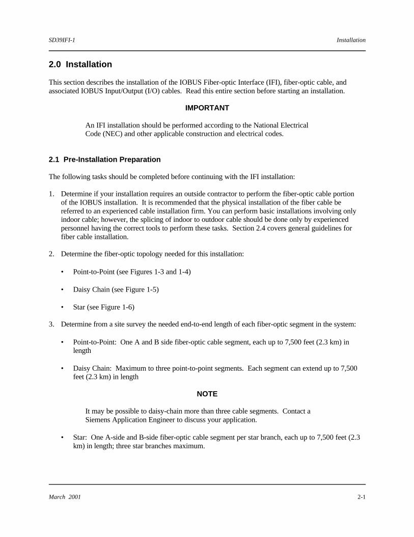
2.1 Pre-Installation Preparation The following tasks should be completed before continuing with the IFI installation: 1. Determine if your installation requires an outside contractor to perform the fiber-optic cable portion
of the IOBUS installation. It is recommended that the physical installation of the fiber cable be referred to an experienced cable installation firm. You can perform basic installations involving only indoor cable; however, the splicing of indoor to outdoor cable should be done only by experienced personnel having the correct tools to perform these tasks. Section 2.4 covers general guidelines for fiber cable installation.
2. Determine the fiber-optic topology needed for this installation:
• Point-to-Point (see Figures 1-3 and 1-4)
• Daisy Chain (see Figure 1-5)
• Star (see Figure 1-6) 3. Determine from a site survey the needed end-to-end length of each fiber-optic segment in the system:
• Point-to-Point: One A and B side fiber-optic cable segment, each up to 7,500 feet (2.3 km) in length
• Daisy Chain: Maximum to three point-to-point segments. Each segment can extend up to 7,500
feet (2.3 km) in length
NOTE
It may be possible to daisy-chain more than three cable segments. Contact a Siemens Application Engineer to discuss your application.
• Star: One A-side and B-side fiber-optic cable segment per star branch, each up to 7,500 feet (2.3
km) in length; three star branches maximum.

Installation SD39IFI-1
March 2001 2-2
4. Determine additional OIMs needed for star topology. (Additional OIMs are only required at local racks; remote racks do not require additional OIMs.)
5. Determine additional HSMs needed for Star topology (Additional HSMs are only required at local
racks; remote racks do not require additional HSMs.) 6. Determine the size and type (indoor or outdoor) of fiber-optic cable to be used in the selected
topology. The IFI assembly has been optimized for use with 62.5/125 graded index micron cable. 7. Determine the number of module racks (MODULRAC, SIXRAC, Remote I/O Rack, or UNIRAC)
needed to house the selected I/O modules. IOBUS capacity is 40 nodes (i.e. one ACM or CCM can communicate with up to 39 I/O modules).
8. Determine the number of IFI-to-IOBUS In cables and IOBUS Out-to-IFI cables needed per IOBus
side. 9. Determine if any I/O module racks in the system will be connected by standard IOBUS cables. The
following lengths of pre-fabricated standard IOBUS cables are available: • IOBUS A and B Cable - 6.6 ft. (2 m)
• IOBUS A and B Cable - 13.1 ft. (4 m)
• IOBUS A and B Cable - 49.2 ft. (15 m)
• IOBUS A and B Cable - 98.4 ft. (30 m)
10. Install all module racks to be connected to an IFI (via IOBUS I/O cables) in their respective
enclosures. Modules need not be installed in the module racks at this time. Refer to the APACS+MODULRAC Installation and Service Instruction (SD39MODULRAC-1)(provided in section 1.4 of this document).
2.2 Environmental Considerations Many industrial environments create severe operating conditions. The conditions at each IFI location must be within the specifications stated in Table 6-2.
CAUTION
Exceeding the specified operating temperature limits can adversely affect performance of an IFI assembly and possibly cause permanent damage to the assembly. Air temperature should be checked periodically to ensure that this specification is not being exceeded.

SD39IFI-1 Installation
March 2001 2-3
To ensure reliable data communications, locate the IFI assembly and APACS+ modules (enclosures) as far as possible from sources of interference, such as high-current electrical equipment that emits strong electromagnetic fields and switching transients. Industrial environments often contain particulate, liquid, and gaseous contaminants. Particulate matter, such as dust and dirt, is abrasive and can cause intermittent contact in connectors associated with card assemblies. Liquid and gaseous contaminants can deteriorate metal, rubber, plastic, card assemblies, and the contacts of cable connectors. Extended exposure to this environment may result in equipment malfunction. To reduce contaminant-related equipment malfunctions, do the following: • Identify contaminants and implement methods to reduce their presence. • Clean equipment and area surrounding the equipment, particularly the floor, by either vacuuming or
wiping with a dampened rag or mop to remove dust and dirt. • Clean or replace regularly all air-conditioning filters, room air filters, and equipment filters. • Inform personnel with access to IFI assemblies of the need for equipment cleanliness. 2.3 Equipment Delivery and Handling The following subsections provide information of interest to shipping, receiving, and warehouse personnel. 2.3.1 Predelivery Test An IFI module for installation is fully tested and inspected by the OEM to ensure proper operation. If the IFI module is ordered factory-installed in a MODULPAC or other enclosure and is included in a factory staging program, the IFI is tested as part of the APACS+ system and inspected to ensure proper operation. 2.3.2 Factory Shipment IFI modules for installation by the user have the individual modules plugged together, and the entire unit placed in protective material and packaged for shipment. Accessories and small attachments (i.e. connectors and cables) are packaged separately. If the IFI module is ordered factory-installed in a MODULPAC or other enclosure, the enclosure is bolted to a pallet and wrapped for protection during shipment.
Installation SD39IFI-1
March 2001 2-4
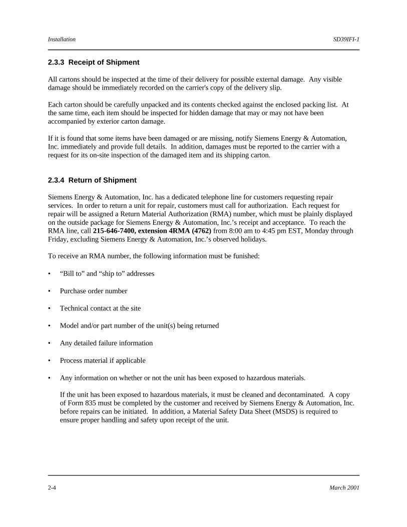
2.3.3 Receipt of Shipment All cartons should be inspected at the time of their delivery for possible external damage. Any visible damage should be immediately recorded on the carrier's copy of the delivery slip. Each carton should be carefully unpacked and its contents checked against the enclosed packing list. At the same time, each item should be inspected for hidden damage that may or may not have been accompanied by exterior carton damage. If it is found that some items have been damaged or are missing, notify Siemens Energy & Automation, Inc. immediately and provide full details. In addition, damages must be reported to the carrier with a request for its on-site inspection of the damaged item and its shipping carton. 2.3.4 Return of Shipment Siemens Energy & Automation, Inc. has a dedicated telephone line for customers requesting repair services. In order to return a unit for repair, customers must call for authorization. Each request for repair will be assigned a Return Material Authorization (RMA) number, which must be plainly displayed on the outside package for Siemens Energy & Automation, Inc.’s receipt and acceptance. To reach the RMA line, call 215-646-7400, extension 4RMA (4762) from 8:00 am to 4:45 pm EST, Monday through Friday, excluding Siemens Energy & Automation, Inc.’s observed holidays. To receive an RMA number, the following information must be funished: • “Bill to” and “ship to” addresses • Purchase order number • Technical contact at the site • Model and/or part number of the unit(s) being returned • Any detailed failure information • Process material if applicable • Any information on whether or not the unit has been exposed to hazardous materials. If the unit has been exposed to hazardous materials, it must be cleaned and decontaminated. A copy
of Form 835 must be completed by the customer and received by Siemens Energy & Automation, Inc. before repairs can be initiated. In addition, a Material Safety Data Sheet (MSDS) is required to ensure proper handling and safety upon receipt of the unit.
SD39IFI-1 Installation
March 2001 2-5
2.3.5 Equipment Handling Special handling procedures are required when an IFI assembly is removed or installed. These procedures are required to prevent component damage from the electrostatic discharge (ESD) hazard to which most semiconductors are vulnerable. When handling a module, use the Siemens Energy & Automation, Inc. Maintenance Kit (P/N 15545-110), which contains a wrist strap and conductive mat. 2.3.6 Equipment Storage The environmental storage temperature and humidity parameters provided in Table 6-2 must be met for storage of an IFI assembly. 2.4 Fiber-optic Cable Installation This section contains basic guidelines for the installation of fiber-optic cables in an indoor and outdoor environment. Fiber-optic cable can be installed using many of the techniques employed for coaxial cable. 2.4.1 Site Survey Conduct a site survey to identify areas that need to be avoided in your routing plan for the fiber cable. The site survey results should be documented and distributed to the cable installation personnel. Note the following conditions: • Physical hazards, such as high-temperature machinery • Physical hazards such as an industrial process that spills or sprays a very hot or corrosive substance
• Physical hazards, such as operating machinery having rotating or sliding attachments • Environmental hazards affecting outdoor cable, such as freezing water, ground disruption from
construction, and rodents
• Limitations imposed by local building codes or regulations
• Limitations imposed by the National Electric Code (NEC)
• Most favorable locations for the placement and set up of the cable let-off/pulling equipment
• Recommended splice locations, where a cable exits or enters a building
Installation SD39IFI-1
March 2001 2-6
2.4.2 Fiber-optic Cable Routing Design Create routing documentation as follows and provide to cable system installers to route the fiber-optic cable:
1. Consult the system drawings and note the network topology required and the locations of all
enclosures to which the fiber-optic cables are to be routed.
2. Using the information noted in step 1, and that gathered from the site survey, design the layout of the fiber-optic cable network.
3. A permanent record of the network's topology should include the following:
• Fiber-optic cable routes
• Length of each fiber-optic cable segment
• Fiber-optic cable segment identifier identification
- If applicable, identify points where fiber-optic cable is to be aerially suspended
- Identify points where fiber-optic cable is to be laid in tray or trough or secured to polls, walls, or building structural members.
- Splice locations (if any)
2.4.3 Cable Pulling and Installation
IMPORTANT
The cable installation must be in accordance with the National Electric Code (NEC) and all local regulations and building codes.
Cable installation consists of routing and installing cable segments between pairs of IFI assemblies to which the cable segment is to be connected until all cable segments comprising the cable system are installed. General installation guidelines applicable to both the A and B sides of the optical IOBUS are listed as follows:
• Refer to your site survey and cable routing design (see sections 2.4.1 and 2.4.2 of this document) for
cable routing, cable lengths, and other information.
• Fibers are sensitive to moisture. The pulling end should be covered with tape or an end cap at all times.
• Never leave the let-off reel unattended, as any binding in the reel may cause a difficult pull that can overstress the cable.

SD39IFI-1 Installation
March 2001 2-7
• Do not exceed cable minimum bend radius. It is permissible to coil fiber cable as long as the minimum bend radius is not violated.
• Do not exceed cable maximum recommended load (tension) when pulling.
• Route the cable ends into their respective destination enclosures. Leave extra cable at the beginning and ends of the cable run.
• Leave extra cable at the designated splice points.
• Consult cable specifications and identify the strength material. If the strength material can be knotted, it can be tied directly to a pulling device.
• If the cable cannot be pulled directly, consider using a "Kellems Grip."
• Pull the cable prior to connector attachment.
• To lower cable-pulling friction, use a cable lubricant. Lubricate conduits prior to pulling the cable. • Installation procedures for open placement of fiber cables are the same as for electrical cables. Lay
cable in cable tray or trough, or secure a cable to posts, walls, or other building structural members. Do not crush the trunk cable with attachment devices.
• If a section of the cable run is going to be suspended, do not stretch the cable between posts without
adequate support. The types of support that can be used to suspend the cable include helical lashing, clamping, or tied mounting.
• After cable segments that require splicing have been installed, splice the cables. Only experienced personnel should perform cable splicing, as the power loss at the splice is critical. Consider the following when selecting a splicing method:
- Fusion splicing is recommended. Fusion splices are made by positioning cleaned, cleaved (cut)
fiber ends between two electrodes and applying an electric current to fuse the ends together. Splices with losses less than 0.2 dB per splice are possible by experienced operators.
- Mechanical splicing, such as in-line connector-to-connector splicing, is not recommended. This method typically produces losses of 1.5 dB per splice.
• After the cables have been routed to their enclosure destinations, the cable connectors can be attached. The 62.5/125 micron fiber cable that is recommended for installation requires ST style connectors for connection to the IFI’s OIM (Optical Interface Modules) and HSM (Hand Shake Modules).
• When all the optical cables have been installed, splices made, and connectors attached, measure the
optical power to ensure that the system is capable of delivering the required power. Use the following procedures to measure the optical power:

Installation SD39IFI-1
March 2001 2-8
- Measure and record the output power from the optical interface’s transmitter at the IFI on one end of the cable segment. Refer to specifications in section 6 of this document for an acceptable value.
- Connect the transmitter fiber of the duplex cable to the transmitter. At the other end of the cable, directly read and record the transmitted power with an optical power meter. The minimum acceptable power to the receiver is 4ìW. Repeat the test for the second (receiver) fiber.
- Since fiber losses over a length of cable can be calculated from the cable specifications, a transmission loss greater than 1.0 to 1.5 dB above fiber losses may indicate that an inferior attached connector requires replacement.
2.5 IFI Mechanical Installation Installation of the IFI onto DIN rails is described in this section. 2.5.1 IFI Assembly Installation IFI assemblies are typically shipped plugged together. Modules not plugged together will be shipped individually packaged in protective, sealed, static shielding bags. Refer to section 2.3.5 for module handling considerations and sections 2.5.1.1, 2.5.1.2, and 2.5.1.3 for module installation. 2.5.1.1 Electrical Interface Module Installation
1. Place the wrist strap from the Siemens Kit P/N 15545-110 on your wrist. 2. Remove the module from its protective bag. Firmly install the module onto the DIN rail by inserting
the bottom notch onto the DIN rail. Then rotate the module upwards, until the spring-loaded latch engages the back of the top edge of the DIN rail (see Figure 2-1).

SD39IFI-1 Installation
March 2001 2-9
Figure 2-1 Module Fully Mounted onto DIN Rail
2.5.1.2 Optical Interface Module Installation 1. Place the wrist strap from Siemens Energy & Automation, Inc. Kit P/N 15545-110 on your wrist.
2. Remove the module from its protective bag. Ensure the address jumper on the module's PC board is
set to the correct position (refer to Figure 2-3). Firmly install the module onto the DIN rail by inserting the bottom notch onto the DIN rail. Then rotate the module upwards, until the spring-loaded latch engages the back of the top edge of the DIN rail.
2.5.1.3 Hand Shake Module Installation 1. Place the wrist strap from Siemens Energy & Automation, Inc. Kit P/N 15545-110 on your wrist. 2. Remove the module from its protective bag. Ensure the LOCAL/REMOTE jumper on the module’s
PC board is set to the correct position. Firmly install the module onto the DIN rail by inserting the bottom notch onto the DIN rail. Then rotate the module upwards, until the spring-loaded latch engages the back of the top edge of the DIN rail.
Installation SD39IFI-1
March 2001 2-10
2.6 Electrical Installation This section describes power supply DC cable connection, IOBUS In/Out cable connection, fiber-optic cable connection, and module switch settings.
NOTE
Do not apply power to the unit until all connections are completed.
CAUTION
Do not apply more than 7-inch-pounds torque when tightening electrical connectors.
2.6.1 IOBUS IN/OUT-to-IFI Cable Connection The four IOBUS-to-IFI copper wire cables listed in Table 2-1 connect the IFI assemblies' A-side and B-side electrical interface modules to the module rack’s A and B IOBUS. Connect the IOBUS A and B cables as follows: 1. Connect the IOBUS A and B OUT cables. Consult user cable drawings and identify the location and rack number of the module rack where the controller resides for this APACS+ I/O system.
NOTE
If a Bus Diverter Module (BDM) is associated with the controller, refer to the APACS+ Bus Diverter Module Installation and Service Instruction (SD39BDM-1).
An IOBUS can exit the module rack by way of IOBUS A OUT J19 Connector and IOBUS B OUT P24 Connector on the module rack’s backplane or, if a BDM is involved, the IOBUS cable connectors on the BDM Transition Board. As shown in Figure 2-2, the "OUT" ends of the A and B cables are marked with a graphical symbol of the same design that appears next to the connectors on the module rack’s backplane. This provides additional assurance that the cables will be connected to the correct connector. Refer to Figure 2-2 and Table 2-1 and make the appropriate cable connections.

SD39IFI-1 Installation
March 2001 2-11
2. Connect the IOBUS A and B IN Cables. Consult user cable drawings and identify the location and rack numbers of all the remote I/O module
racks to be connected by fiber-optic cable in this APACS+ I/O System. An IOBUS can enter the module rack only by way of the IOBUS A IN and IOBUS B IN connectors located on the module rack’s backplane. As shown in Figure 2-2, the "IN" ends of the A and B cables are marked with a graphical symbol of the same design that appears next to the OUT connectors on the module rack’s backplane. This provides additional assurance that the cables will be connected to the correct connector. Refer to Table 2-1 and Figure 2-2 and make the appropriate cable connections.
NOTE
Only one A-side and one B-side cable can be used with one IFI assembly. Both cables connect to the IOBUS In or the IOBUS Out connectors, depending on the location of the IFI.
Table 2-1 IOBUS-to-IFI Cable Connection Data
Cable P/N
Cable Designation
Connects From
Connects To
16137-232 IOBUS A OUT Module rack or BDM Transition Board connector A OUT
A-side Electrical Interface Module
16137-233 IOBUS B OUT Module rack or BDM Transition Board connector B OUT
B-side Electrical Interface Module
16137-230 IOBUS A IN Module rack A-side Electrical Interface Module 16137-231 IOBUS B IN Module rack B-side Electrical Interface Module
Installation SD39IFI-1
March 2001 2-12
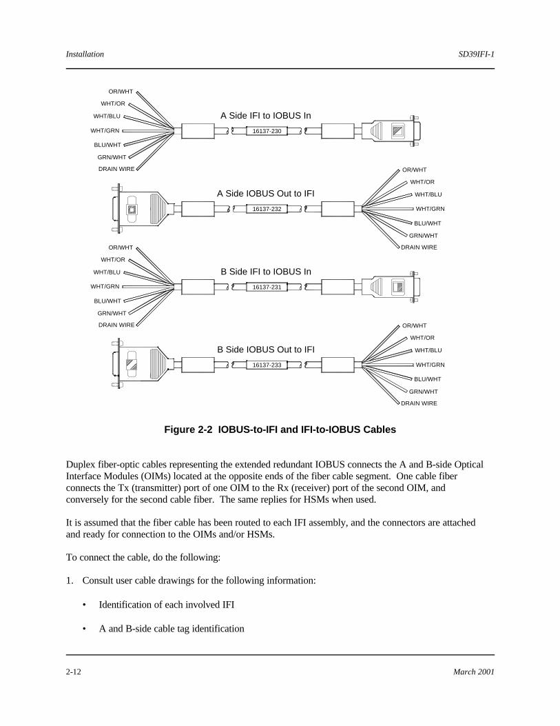
Figure 2-2 IOBUS-to-IFI and IFI-to-IOBUS Cables
Duplex fiber-optic cables representing the extended redundant IOBUS connects the A and B-side Optical Interface Modules (OIMs) located at the opposite ends of the fiber cable segment. One cable fiber connects the Tx (transmitter) port of one OIM to the Rx (receiver) port of the second OIM, and conversely for the second cable fiber. The same replies for HSMs when used.
It is assumed that the fiber cable has been routed to each IFI assembly, and the connectors are attached and ready for connection to the OIMs and/or HSMs. To connect the cable, do the following: 1. Consult user cable drawings for the following information:
• Identification of each involved IFI • A and B-side cable tag identification
16137-230
16137-232
16137-231
16137-233
OR/WHT
WHT/OR
WHT/BLU
WHT/GRN
BLU/WHT
GRN/WHT
DRAIN WIRE OR/WHT
WHT/OR
WHT/BLU
WHT/GRN
BLU/WHT
GRN/WHT
DRAIN WIRE
OR/WHT
WHT/OR
WHT/BLU
WHT/GRN
BLU/WHT
GRN/WHT
DRAIN WIRE
OR/WHT
WHT/OR
WHT/BLU
WHT/GRN
BLU/WHT
GRN/WHT
DRAIN WIRE
A Side IFI to IOBUS In
A Side IOBUS Out to IFI
B Side IFI to IOBUS In
B Side IOBUS Out to IFI

SD39IFI-1 Installation
March 2001 2-13
• Color and tag identification assigned to A-side Rx fiber and Tx fiber connections to each involved IFI assembly
• Color and tag identification assigned to B-side Rx fiber and Tx fiber connections to each involved
IFI assembly
2. Remove the protective caps from the Rx and Tx ports of each involved OIM. 3. Refer to Table 2-2 and connect the cables to their respective ports. Be very careful that the connector
(identified by color and tag) connected to a Tx port on one OIM and HSM connects to the Rx port on the opposite end OIM and HSM and conversely.
Table 2-2 Fiber-optic Cable Connection
Cable Designation
Connects from Local
Connects to Remote
A-Side IOBUS OIM A-Side Tx Port A-Side Rx Port
A-Side IOBUS OIM A-Side Rx Port A-Side Tx Port
B-Side IOBUS OIM B-Side Tx Port B-Side Rx Port
B-Side IOBUS OIM B-Side Rx Port B-Side Tx Port A/B Side OK Loop HSM Tx Port HSM Rx Port
A/B Side Master Enable HSM Rx Port HSM Tx Port
2.6.2 Jumper Settings The Optical Interface and the Hand Shake Modules each contain a jumper located on the component side of their PC boards that must be set to ensure correct system operation. The jumpers must be checked, and, if necessary, reset prior to system power-up. Replacement modules should be checked to ensure that the jumper is set to the same position as the jumper in the module being replaced. 2.6.2.1 Optical Interface Jumper Setting The setting of the Star Address jumper is dependent upon the local OIM’s position in the Star configuration.
NOTE
The remote OIM’s jumper settings do not require adjustment. ESD protection is required when handling this module. Refer to section 3.4.2 for the removal/replacement procedures. Refer to Figure 2-3 to set the jumper.

Installation SD39IFI-1
March 2001 2-14
Figure 2-3 Setting Star Address Jumper Positions 2.6.2.2 Hand Shake Jumper Setting The Hand Shake Module (HSM) contains a Local/Remote jumper, which is dependent upon the location of the IFI assembly. If the IFI assembly is located near the remote I/O, the jumper should be set to REMOTE.
nn

SD39IFI-1 Maintenance
March 2001 3-1
3.0 Maintenance The IFI assembly requires minimal maintenance. Some routine maintenance is recommended in the form of a visual inspection and possible cleaning. 3.1 Tool Requirements Common electronic servicing hand tools are necessary for maintenance. 3.2 Preventive Maintenance The following subsections contain the recommended preventive maintenance procedures. 3.2.1 Visual Inspection Perform periodic visual inspections of the IFI for excessive accumulation of dust, dirt, or other foreign material adhering to a module's circuit board. Accumulation of dirt and dust or corrosive material may cause the mini-rack connector contacts to become intermittent or fail. The frequency of inspection depends on the severity of the operating environment. An IFI installed in a cabinet complying with the NEMA 12/IP55 specification need not be inspected for cleanliness if the cabinet doors are kept closed at all times. 3.2.2 Cleaning Cleaning a module involves brushing or vacuuming the faceplate and circuit card to remove dust and restore cooling efficiency. 3.3 Troubleshooting Error codes are displayed by the operator interface. If the interface's alarm blocks have been configured, IOBUS errors are reported. Error code descriptions and corrective actions are presented in the 4-mation help file and in the APACS+ Module Diagnostic Error Codes Configuration Guide (CG39-19). Failed IFI modules should be replaced with a known good module and the failed module returned to one of the addresses in the warranty statement for repair.

Maintenance SD39IFI-1
March 2001 3-2
3.3.1 IFI Troubleshooting An LED located on the faceplate of an IFI module indicates the module's status (as listed in Table 3-1).
CAUTION
Safety procedures required by corporate procedures or regulations must be followed when maintaining safety instrumental systems.
Table 3-1 Status LED Indications
Module
LED Label
LED Indication
Module Status/Remedy
PWR Steady Green
Black (off)
IFI 24 Vdc power is OK. No 24 Vdc power: • Check that 24 Vdc power is present (redundant
power). • Check for defective module.
Electrical Interface
Module (EIM)
COM Flickering Yellow Black (off)
Electrical communications are performing properly. No electrical communications: • Check associated controller. • Check for defective module.
Optical Interface
Module (OIM)
RX Flickering Yellow
Black (off)
Receiving IOBUS data via fiber Not receiving IOBUS data via fiber: • Check associated controller. • Check that OIM is properly plugged in to EIM. • Check that opposing OIM is transmitting. • Check if fiber-optic cable damaged. • Check if fiber-optic cable is not cross-coupled. • Check for loose or disconnected fiber connectors. • Check TX signal strength at TX port. • Check for defective module.

SD39IFI-1 Maintenance
March 2001 3-3
Table 3-1 (Cont)
Module
LED Label
LED Indication
Module Status/Remedy
Optical
Interface Module (OIM)
TX Flickering Green
Black (off)
Module is transmitting IOBUS data. Module not transmitting: • Check that OIM is properly plugged in to EIM. • Check associated controller. • Check associated EIM module. • Check for loose or disconnected IOBUS
connectors. • Check that fiber-optic cable is not cross-coupled. • Check for loose or disconnected fiber connectors. • Check for defective module.
LOCAL Steady Red Black (off)
Module is in Local mode. Module is not in Local mode.
REMOTE Steady Red Black (off)
Module is in Remote mode. Module is not in Remote mode.
RX Yellow (on) Black (off)
Module is receiving: • Master OK – Local mode • Master Enable – Remote mode Module not receiving: • Check that Master OK electrical signal is in Local
mode. • Check that Master Enable electrical signal is in
Remote mode. • Check for defective module
Hand Shake Module (HSM)
TX Green (on) Black (off)
Module is transmitting: • Master Enable – Local mode • Master OK – Remote mode Module not transmitting: • Check Master Enable voltage signal (Local mode) • Check Master OK current signal (Remote mode) • Check for defective module

Maintenance SD39IFI-1
March 2001 3-4
3.3.2 IFI-to-IOBUS Cable Continuity Check A defective IFI-to-IOBUS cable can cause an IOBUS communication failure that will be reported and logged by APACS+ 4-mation. Refer to Figure 3-1 for the pin-to-pin cable wiring diagrams for the IFI with and without the HSM in order to perform a continuity check of a suspected defective cable.
Figure 3-1 IFI-to-IOBUS Cable Wiring Diagram
OR/WHTWHT/ORWHT/BLUWHT/GRNBLU/WHTGRN/WHT
OR/WHTWHT/OR
DRAIN WIRE
WHT/GRNBLU/WHTGRN/WHT
WHT/BLU
P/N 16137-230 A Side IFI to IOBUS A P/N 16137-231 B Side IFI to IOBUS B
P/N 16137-232 A Side IOBUS Out to IFIP/N 16137-231 B Side IOBUS Out to IFI
DRAIN WIREWHT/OROR/WHT
GRN/WHTBLU/WHT
WHT/BLUWHT/GRN
OR/WHTWHT/ORWHT/BLUWHT/GRNBLU/WHTGRN/WHT
1
6
1
6

SD39IFI-1 Maintenance
March 2001 3-5
3.4 Module Replacement The following subsections provide assembly removal and replacement procedures.
IMPORTANT
Do not restore DC power until protective cover is installed and all electrical and optical modules have been plugged together.
3.4.1 EIM (Electrical Interface Module) Removal/Replacement The module can be removed and inserted in a redundantly powered IFI.
Remove the module as follows: 1. Removal of an EIM from either the A or B side of the IFI interrupts communications to the associated
module rack on that side of the IOBUS. Ensure that the remaining side of the IOBUS is operational so that the process is not disturbed. If all IOBUS communications are to be halted, determine if it is advisable to idle or shut down the process.
2. Disconnect the appropriate IOBUS A or B cable and the 24 Vdc cable from the module by prying off
the connector or by loosening the screws and removing the wires. 3. Place the wrist strap from Siemens Energy & Automation, Inc. Kit P/N 15545-110 on your wrist.
Separate the EIM from the other modules. Slide the release mechanism upwards while pivoting the module downwards. Place the module in a bag for protection and return to the factory.
Replace the module as follows: 1. Reconnect the IOBUS A or B cable and the 24 Vdc cable to the new module. 2. Refer to section 2.5.2.1 for the installation of the new module. 3. If appropriate, restore the process to operational status. 3.4.2 OIM (Optical Interface Module) Removal/Replacement The module can be removed and inserted in a redundant powered IFI. Remove the module as follows: 1. Removal of an OIM from either the A or B side of the IFI interrupts received and transmitted
communications to and from the associated module rack on that side of the IOBUS. Ensure that the remaining side of the IOBUS is operational so that the process is not disturbed. If all IOBUS communications are to be halted, determine if it is advisable to idle or shut down the process.

Maintenance SD39IFI-1
March 2001 3-6
2. Disconnect the fiber-optic Rx and Tx cables from the module. Tag the cables to ensure correct re-connection.
3. Place the wrist strap from Siemens Energy & Automation, Inc. Kit P/N 15545-110 on your wrist.
Separate the OIM from the other modules. Slide the release mechanism upwards while pivoting the module downwards. Note the position of the Address jumper on the module's PC board. The replacement module's Address jumper must be set to the same position. Place the module in a bag for protection and package it for return to the factory.
Replace the module as follows: 1. Ensure that the Address jumper on the module's PC board is set to the same position as the module
being replaced. 2. Reconnect the fiber-optic Rx and Tx cables to the module. Disconnect the wrist strap ground wire
from the IFI. 3. Refer to section 2.5.2.2 for the installation of the new module. 4. If appropriate, restore the process to operational status.
CAUTION
Do not use magnification (such as a microscope or other focusing equipment) when viewing the optical output of the device.
3.4.3 HSM (Hand Shake Module) Removal/Replacement Only a redundant HSM can be removed and inserted in a redundant powered IFI. Remove the module as follows: 1. Removal of an HSM from either the A or B side of the IFI will interrupt received and transmitted
communications to and from the associated module rack on that side of the IOBUS. Ensure that the remaining side of the IOBUS is operational so that the process is not disturbed. If all IOBUS communications will be halted, determine if it is required to idle or shut down the process.
2. Disconnect the fiber-optic Rx and Tx cables from the module. Tag the cables to ensure correct re-
connection. 3. Remove the four wires from the cable connector (four wires for A side and four wires for B side).
SD39IFI-1 Maintenance
March 2001 3-7
4. Place the wrist strap from Siemens Energy & Automation, Inc. Kit P/N 15545-110 on your wrist. Separate the HSM from the other modules. Slide the release mechanism upwards while pivoting the module downwards. Note the position of the LOCAL/REMOTE jumper on the module's PC board. The replacement module's LOCAL/REMOTE jumper must be set to the same position. Place the module in a bag for protection and package it for return to the factory.
Replace the module as follows: 1. Replace the four wires connecting to the cable connector. 2. Reconnect the fiber-optic Rx and Tx cables to the module. Disconnect the wrist strap ground wire
from the IFI. 3. Refer to section 2.5.1.3 for the installation of the new module. 4. If appropriate, restore the process to operational status. 3.5 Spare and Replacement Parts One spare Electrical Interface Module, one spare Optical Interface Module, and one spare Hand Shake Module, if used, should be stocked. Spares can be ordered from one of the addresses in the Warranty statement or through a local Siemens Energy & Automation, Inc. representative. When ordering, provide the part number from the module's nameplate and a purchase order number. Assembly part numbers are stated in Section 5.0 and printed on most modules. 3.6 Maintenance Records An accurate record-keeping system for tracking maintenance operations should be established and updated. Data extracted from the record may serve as a base for ordering maintenance supplies, including spare parts. The record may also be useful as a troubleshooting tool. In addition, maintenance records may be required to provide documentary information in association with a service contract. It is suggested that the following information be recorded:
• Date of service incident
• Name or initials of service person
• Brief description of incident symptoms and repairs performed
• Replacement part or assembly number
• Software compatibility code of original part (if applicable)
• Software code of replacement part (if applicable)

Maintenance SD39IFI-1
March 2001 3-8
• Serial number of original part
• Serial number of replacement part
• Issue number of original circuit module.
• Issue number of replacement circuit module. • Date of completion
n

SD39IFI-1 Circuit Description
March 2001 4-1
4.0 Circuit Description
This section provides a brief component description and block diagram-level description of the IOBUS Fiber-Optic Interface (IFI) and an introduction to basic fiber-optics. 4.1 IFI Components The IFI is a dual (IOBUS A and B) fiber-optic interface modem with a modular format with the following three basic components: • Electrical Interface Module (EIM): The EIM, one per IOBUS side, is installed on the left side of
the IFI assembly. A copper wire IOBUS cable connects the EIM to the APACS+/QUADLOG I/O modules and controller (ACM/CCM) via the module rack’s A or B IOBUS. The EIM conditions signals supplied to and from the IFI for transmission over the fiber-optic network.
• Optical Interface Module (OIM): The OIM connects the IFI (modem) with the fiber-optic network
permitting the optical signal to be transmitted to and received from a remote IFI. Up to three OIMs can be installed in an assembly to form a 3-port hub, from which a star network architecture can be configured. Use 62.5/125-micron fiber cables with ST connectors.
•• Hand Shake Module (HSM): The HSM for APACS+ node-to-node redundant systems or any
QUADLOG system, including peer-to-peer, node-to-node, and stand-alone, is installed between two EIM/OIM pairs. The HSM extends the master enable and master OK signals in APACS+ rack-to-rack redundant and QUADLOG systems. Use 62.5/125-micron fiber cables with ST connectors.
4.2 IFI Operation The IFI allows the APACS+ IOBUS to be extended from a local module rack (MODULRAC, SIXRAC, 4-slot Remote I/O Rack, or UNIRAC) to remote I/O module racks over a fiber-optic network. Because fiber- optic cable has an extremely low attenuation rate compared to conventional copper wire IOBUS cable used by the APACS+ system, a considerably longer cable run (7,500ft. per cable segment) to remote I/O is possible. The block diagram shown in Figure 4-1 illustrates the operation of an IFI in a point-to-point fiber-optic communication network. A Star network (refer to Figure 1-6) can also be configured with the IFI where transmissions from the master controller (ACM or CCM) fan out via three optical interfaces in the IFI to remote I/O.
NOTE
The IFI assembly cannot be used for any APACS+ or QUADLOG node-to-
node redundant architectures in a Star fiber-optic topology.
Circuit Description SD39IFI-1
March 2001 4-2
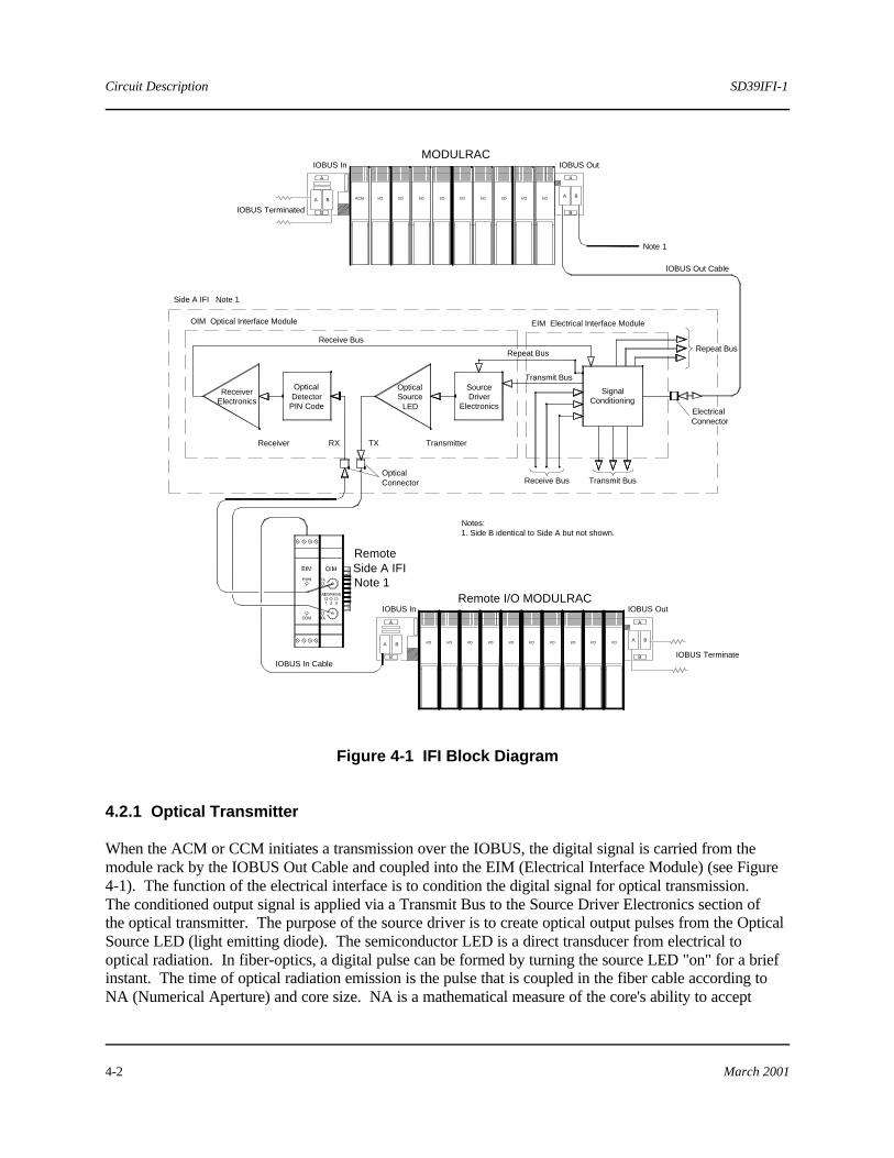
Figure 4-1 IFI Block Diagram 4.2.1 Optical Transmitter When the ACM or CCM initiates a transmission over the IOBUS, the digital signal is carried from the module rack by the IOBUS Out Cable and coupled into the EIM (Electrical Interface Module) (see Figure 4-1). The function of the electrical interface is to condition the digital signal for optical transmission. The conditioned output signal is applied via a Transmit Bus to the Source Driver Electronics section of the optical transmitter. The purpose of the source driver is to create optical output pulses from the Optical Source LED (light emitting diode). The semiconductor LED is a direct transducer from electrical to optical radiation. In fiber-optics, a digital pulse can be formed by turning the source LED "on" for a brief instant. The time of optical radiation emission is the pulse that is coupled in the fiber cable according to NA (Numerical Aperture) and core size. NA is a mathematical measure of the core's ability to accept
A
A
B
B
A
B
A B
IOBUS InMODULRAC
IOBUS Terminated
IOBUS Out
Note 1
Side A IFI Note 1
ReceiverElectronics
OpticalDetector
PIN Code
OpticalSource
LED
SourceDriver
Electronics
SignalConditioning
Receiver TransmitterTXRX
OpticalConnector
Receive Bus
Repeat Bus
Transmit Bus
Receive Bus Transmit Bus
ElectricalConnector
Repeat Bus
OIM Optical Interface Module EIM Electrical Interface Module
IOBUS Out Cable
Remote I/O MODULRACIOBUS Out
IOBUS Terminate
B
B
A
A
BA
B
A
IOBUS In
IOBUS In Cable
Notes:1. Side B identical to Side A but not shown.
RemoteSide A IFINote 1
I/O I/O I/O I/O I/O I/O I/O I/O I/OACM
I/O I/O I/O I/O I/O I/O I/O I/OI/O I/O

SD39IFI-1 Circuit Description
March 2001 4-3
lightwaves from various angles and to transmit them down to the core. Using a light source not matched to a particular fiber's NA and core causes less than optimum light coupling for the system. The fiber-optic cable that is connected to the Tx port of the optical interface is connected to the Rx port of the optical interface in the remote IFI. The maximum allowable cable length between IFIs is 7,500 ft. Because the IFI's transmitter emits sufficient power, and its receiver is sensitive enough, limiting fiber cable segments to this distance ensures that the system operates without requiring power budget calculations. The leading causes of optical attenuation in a fiber cable are the following: • Coupling loss - dependent upon the fiber's NA and core size and the source emitter (LED or laser) • Optical fiber loss (see section 4.3.1) • Connector loss - a function of the physical alignment of one fiber core to another 4.2.2 Optical Receiver The ACM or the CCM’s transmission is coupled into the Rx port of the optical interface in the remote IFI and applied to the Optical Detector PIN Diode section of the optical receiver. The PIN (positive-intrinsic-negative) photodiode captures the lightwave pulses for conversion back into electrical current. The photons of light (lightwave pulses) generate photoelectrons within the PIN diode that are amplified by the receiver electronics and applied via the Receive Bus to the electrical interface for conditioning. The conditioned output signal from the electrical interface is carried by the IOBUS In Cable to the remote I/O module rack and distributed across the IOBUS to all I/O modules. 4.2.3 Repeater Operation An IFI transmission received by a particular optical interface module in a remote IFI is repeated by other optical interface modules that are installed in the remote IFI. As shown in Figure 4-1, separate Repeat Buses connect the Signal Conditioner to the Source Driver Electronics in the transmitters of the Optical Interface Modules. If a second optical interface were installed in the remote IFI shown in Figure 4-1, the incoming transmission from the ACM (after processing by the receiver and conditioning by the electrical interface) would be routed by the electrical interface via the Repeat Bus to the transmitter in the second OIM and re-transmitted a maximum 7,500 ft. to other remote I/O. 4.3 Basic Fiber-optics An introduction to fiber-optic technology is provided in this section. The structural elements of an optical fiber are as follows: • Fiber Structure
ñ Core - The core is the light transmission area of the fiber, either glass or plastic. A large core
allows more light to be transmitted into the fiber as the light collection efficiency is proportional to the relative area of the fiber.
Circuit Description SD39IFI-1
March 2001 4-4
ñ Cladding - Applied over the outer surface of the fiber, cladding provides a lower refractive index at the core surface in order to cause reflection within the core to improve lightwave transmission through the fiber.
ñ Coating - Applied over the cladding, coatings are typically multi-layers of plastic applied to preserve fiber strength, absorb shock, and provide additional fiber protection.
•• Fiber Size - The size of an optical fiber is defined by its structural elements; the outer diameter of its
core and cladding. For example: 62.5/125 refers to a fiber with a core of 62.5 microns and a cladding of 125 microns. However, literature typically refers to fiber size by its core. For example: "200" fiber means its core is 200 microns. A micron (ìm) is equal to 1/1,000,000 of a meter.
• Fiber Types - Fiber is identified by the type of paths the lightwaves travel within the fiber core.
There are two basic types of fiber: multimode (graded index and step index; see Figure 4-2) and single mode.
ñ Graded Index Multimode - The graded index multimode core contains multiple layers of glass
that guide the light rays down the fiber in multiple pathways. Each layer of glass has a lower index of refraction proceeding outward from the axis. This speeds up the light rays in the outer layers to match those rays traveling the shorter pathway directly down the axis. The gradual redirection of lightwaves back toward the core's axis results in equalized propagation times of the various modes. This allows data to be sent over longer distances and higher rates before modal dispersion (overlapping of light pulses) becomes a factor.
ñ Step Index Multimode - The step index multimode fiber features a sharp steplike difference in
the refractive index of the core and cladding. The index of refraction of the core is a constant until it reaches the cladding, where it steps sharply to a lower value. The lightwaves reflecting from the boundary of the core and cladding travel at different angles as they zigzag down the fiber and arrive at the receiver end at different times. This variance in arrival time causes modal dispersion, the overlapping of pulses. Because dispersion is greater in a step index multimode fiber than in a graded index multimode fiber, it is used for shorter runs and lower operating frequencies (e.g. 20 MHz-km).

SD39IFI-1 Circuit Description
March 2001 4-5
Figure 4-2 Graded and Step Index Multimode Fibers
ñ Single Mode - A single mode fiber only allows a single light ray or mode to be transmitted down the core. This eliminates the distortion due to the overlapping of light pulses. The core of a single-mode fiber is extremely small, approximately 5 to 10 microns. A single-mode fiber has a very high capacity and capability compared to multimode fiber. A single-mode fiber can easily transmit 40 channels of video for 15 miles without a repeater. Single-mode fiber is used typically with laser light sources because of their spectral purity.
• Numerical Aperture - In addition to core size, the ability of fiber to collect optical power (light) is
called numerical aperture (NA). This is a mathematical measure of the fiber core's ability to accept lightwaves from various angles (acceptance cone) and transmit them down to the core. A large difference between the refractive indices of the core and cladding means a larger NA. For equal core sizes, a fiber with a larger NA accepts more light. A power increase by a factor of two is realized by going from an NA of 0.20 to one of 0.29. Figure 4-3 illustrates numerical aperture.
Optical modems use a Light Emitting Diode (LED) to illuminate the fiber. The light from the LED is
radiated from a spot approximately 100 microns in diameter and disperses at a 45-degree angle. The end of the fiber is anchored approximately 50 microns from the LED's spot. Advantages of 200-micron cable are as follows:
ñ The core is approximately as large as the LED's radiation spot.
ñ A large NA permits the capture of lightwaves that are 20 degrees from the axis of the core (shown
as "è" in Figure 4-3). The acceptance cone for 200-micron fiber is approximately 40 degrees.

Circuit Description SD39IFI-1
March 2001 4-6
Figure 4-3 Numerical Aperture • Optical Performance Factors – The following two optical fiber factors affect transmission
performance:
ñ Bandwidth - Bandwidth is a measure of the data-carrying capacity of the fiber. Bandwidth is expressed in a frequency-distance format (MHZ-km). Because of their large comparative bandwidth, fibers can carry large amounts of information. A fiber cable listed as “100 MHZ cable” can move 100 MHz of data one kilometer. Spectral dispersion provides the principle bandwidth limitation for LED source systems of 850 nm (nanometers). Spectral dispersion is caused by different wavelengths of light traveling at different velocities through the fiber. When an LED is the spectral source, as opposed to a laser source, the LED emits a spectral range 20 times that of the laser.
ñ Attenuation - Attenuation is the reduction of optical power as it travels to and through the fiber.
Attenuation is expressed in dB/km (decibels per kilometer) at a specified wavelength for each fiber type. The most favorable transmission regions within the optical spectrum for a fiber fall in the infrared region. The 800 to 900 nm and 1,100 to 1,300 nm regions have the lowest attenuation. Wavelength is measured in nanometers (nm), the distance between two cycles of the same wave. Fibers are optimized for operation at the most often specified wavelengths of 850 and 1,300 nm. Losses at different wavelengths occur in the fiber due to absorption, reflection, and scattering. The amount of loss depends on the specific fiber, its size, purity, and refraction indexes.
n

SD39IFI-1 IFI Components and IOBUS Cables
March 2001 5-1
5.0 IFI Components and IOBUS Cables 5.1 IFI Components The IFI is a configurable assembly and may contain other components (see those listed in Table 5-1).
Table 5-1 IFI Components
Component Description
Siemens
Part Number
Electrical Interface Module (EIM) 16804-42 Optical Interface Model (OIM) 16804-43 Hand Shake Module (HSM) 16804-44
5.2 IFI IOBUS Cables For optical segments of the IOBUS cable installation, a 62.5/125 multimode-graded index micron cable can be used alternatively. Recommended cables are available for the IFI configurations with and without the optional Hand Shake Module. Tables 5-2 lists the cable part numbers that apply to both configurations.
Table 5-2 IFI IOBUS Cables
Cable Description
Siemens
Part Number
IOBUS A OUT to IFI Cable, 6.6 ft. (2 m) 16137-232 IOBUS B OUT to IFI Cable, 6.6 ft. (2 m) 16137- 233 IFI to IOBUS A IN Cable, 6.6 ft. (2 m) 16137- 230 IFI to IOBUS B IN Cable, 6.6 ft. (2 m) 16137- 231
n

IFI Components and IOBUS Cables SD39IFI-1
March 2001 5-2
SD39IFI-1 Specifications
March 2001 6-1
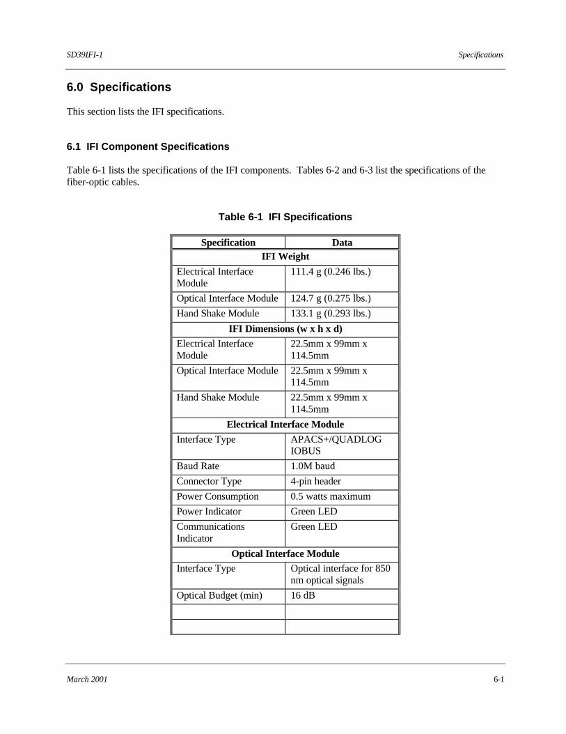
6.0 Specifications This section lists the IFI specifications. 6.1 IFI Component Specifications Table 6-1 lists the specifications of the IFI components. Tables 6-2 and 6-3 list the specifications of the fiber-optic cables.
Table 6-1 IFI Specifications
Specification Data IFI Weight
Electrical Interface Module
111.4 g (0.246 lbs.)
Optical Interface Module 124.7 g (0.275 lbs.)
Hand Shake Module 133.1 g (0.293 lbs.)
IFI Dimensions (w x h x d)
Electrical Interface Module
22.5mm x 99mm x 114.5mm
Optical Interface Module 22.5mm x 99mm x 114.5mm
Hand Shake Module 22.5mm x 99mm x 114.5mm
Electrical Interface Module
Interface Type
APACS+/QUADLOG IOBUS
Baud Rate 1.0M baud
Connector Type 4-pin header
Power Consumption 0.5 watts maximum
Power Indicator Green LED
Communications Indicator
Green LED
Optical Interface Module Interface Type Optical interface for 850
nm optical signals
Optical Budget (min) 16 dB
Specifications SD39IFI-1
6-2 March 2001
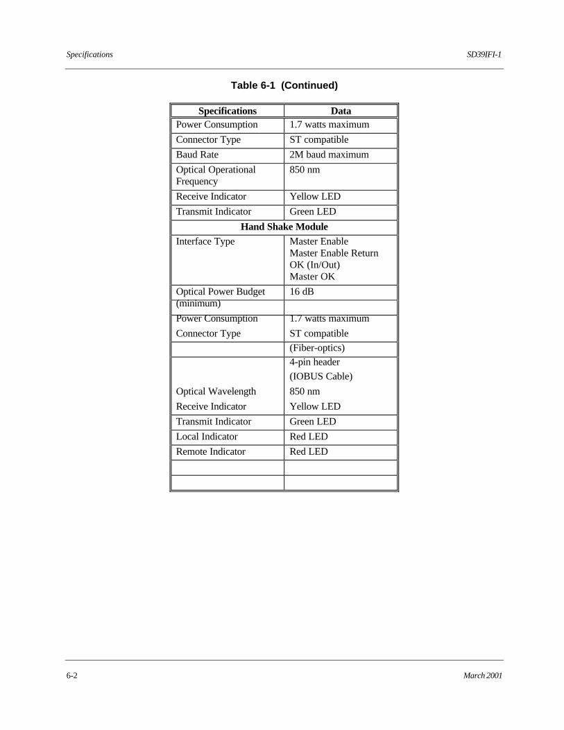
Table 6-1 (Continued)
Specifications Data Power Consumption 1.7 watts maximum
Connector Type ST compatible
Baud Rate 2M baud maximum
Optical Operational Frequency
850 nm
Receive Indicator Yellow LED
Transmit Indicator Green LED
Hand Shake Module Interface Type
Master Enable Master Enable Return OK (In/Out) Master OK
Optical Power Budget (minimum)
16 dB
Power Consumption 1.7 watts maximum
Connector Type
ST compatible
(Fiber-optics) 4-pin header
(IOBUS Cable)
Optical Wavelength 850 nm
Receive Indicator Yellow LED
Transmit Indicator Green LED
Local Indicator Red LED
Remote Indicator Red LED
SD39IFI-1 Specifications
March 2001 6-3
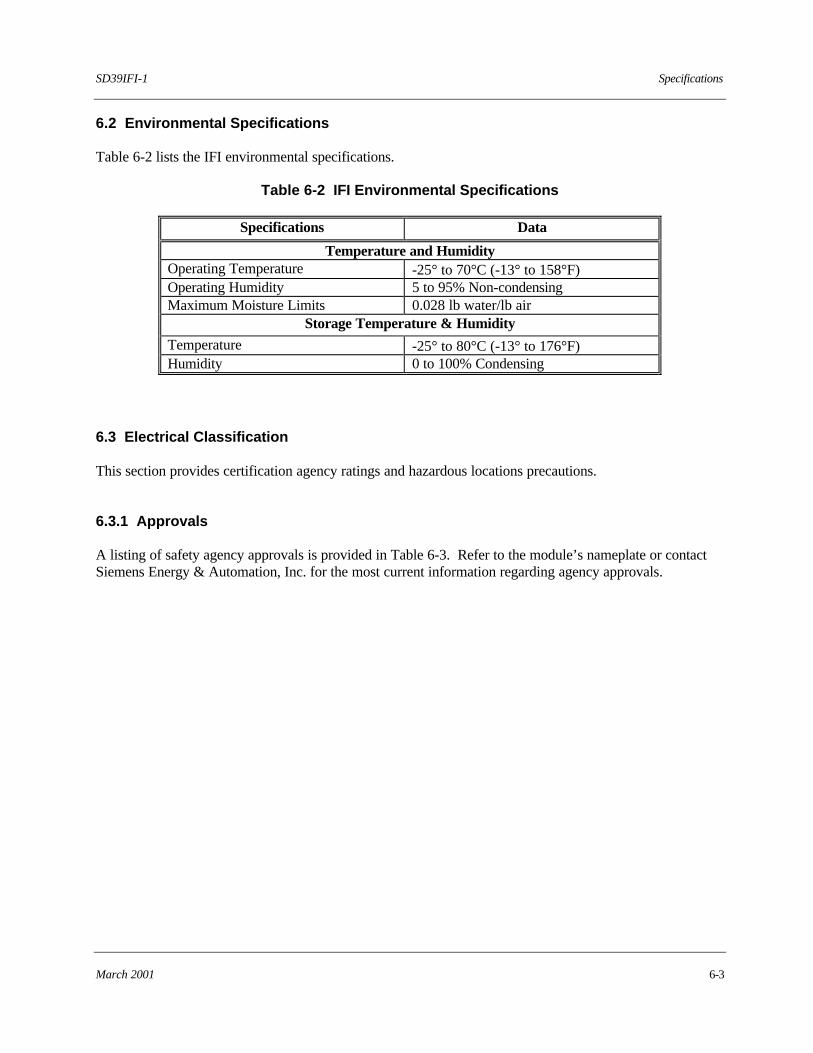
6.2 Environmental Specifications Table 6-2 lists the IFI environmental specifications.
Table 6-2 IFI Environmental Specifications
Specifications Data
Temperature and Humidity Operating Temperature -25° to 70°C (-13° to 158°F) Operating Humidity 5 to 95% Non-condensing Maximum Moisture Limits 0.028 lb water/lb air
Storage Temperature & Humidity
Temperature -25° to 80°C (-13° to 176°F) Humidity 0 to 100% Condensing
6.3 Electrical Classification This section provides certification agency ratings and hazardous locations precautions. 6.3.1 Approvals A listing of safety agency approvals is provided in Table 6-3. Refer to the module’s nameplate or contact Siemens Energy & Automation, Inc. for the most current information regarding agency approvals.
Specifications SD39IFI-1
6-4 March 2001
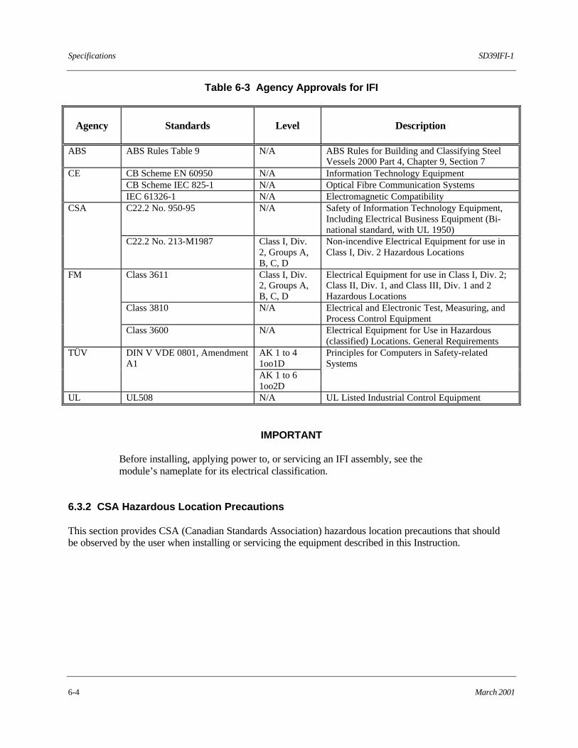
Table 6-3 Agency Approvals for IFI
Agency
Standards
Level
Description
ABS ABS Rules Table 9 N/A ABS Rules for Building and Classifying Steel
Vessels 2000 Part 4, Chapter 9, Section 7 CB Scheme EN 60950 N/A Information Technology Equipment CB Scheme IEC 825-1 N/A Optical Fibre Communication Systems
CE
IEC 61326-1 N/A Electromagnetic Compatibility C22.2 No. 950-95 N/A Safety of Information Technology Equipment,
Including Electrical Business Equipment (Bi-national standard, with UL 1950)
CSA
C22.2 No. 213-M1987 Class I, Div. 2, Groups A, B, C, D
Non-incendive Electrical Equipment for use in Class I, Div. 2 Hazardous Locations
Class 3611 Class I, Div. 2, Groups A, B, C, D
Electrical Equipment for use in Class I, Div. 2; Class II, Div. 1, and Class III, Div. 1 and 2 Hazardous Locations
Class 3810 N/A Electrical and Electronic Test, Measuring, and Process Control Equipment
FM
Class 3600 N/A Electrical Equipment for Use in Hazardous (classified) Locations. General Requirements
AK 1 to 4 1oo1D
TÜV DIN V VDE 0801, Amendment A1
AK 1 to 6 1oo2D
Principles for Computers in Safety-related Systems
UL UL508 N/A UL Listed Industrial Control Equipment
IMPORTANT
Before installing, applying power to, or servicing an IFI assembly, see the module’s nameplate for its electrical classification.
6.3.2 CSA Hazardous Location Precautions This section provides CSA (Canadian Standards Association) hazardous location precautions that should be observed by the user when installing or servicing the equipment described in this Instruction.

SD39IFI-1 Specifications
March 2001 6-5
WARNING
Failure to observe the following precautions could result in an explosion hazard.
• For Class I, Division 2 hazardous locations: Use only factory-authorized replacement parts. Substitution of components can impair the suitability of this equipment for hazardous locations. • For Division 2 hazardous locations: When the equipment described in this Instruction is installed without safety barriers, the following precautions should be observed. Switch off electrical power at its source (in non-hazardous location) before connecting or disconnecting power, signal, or other wiring.
6.3.3 Special Conditions for Safe Use • Use of the equipment in a manner not specified by the manufacturer may impair the protection
provided by the equipment. • End clamps (Part Number 7418-516), included with base assemblies, must be installed at both ends of
assembly if Class I, Division 2, hazardous location. • Route electrical power to the equipment through a clearly labeled circuit breaker or on-off switch that
is located near the station and is accessible by the operator. The breaker or switch should be located in a non-explosive atmosphere unless suitable for use in an explosive atmosphere.
• A Declaration of Conformity with the standards or other normative documents stated on the certificate
is provided at the back of this document.
n

Specifications SD39IFI-1
6-6 March 2001

Declaration of Conformity

Warranty The Company warrants all equipment manufactured by it and bearing its nameplate, and all repairs made by it, to be free from defects in material and workmanship under normal use and service. If any part of the equipment herein described, and sold by the Company, proves to be defective in material or workmanship and if such part is within twelve months from date of shipment from the Company's factory, returned to such factory, transportation charges prepaid, and if the same is found by the Company to be defective in material or workmanship, it will be replaced or repaired, free of charge, f.o.b. Company's factory. The Company assumes no liability for the consequence of its use or misuse by Purchaser, his employees or others. A defect in the meaning of this warranty in any part of said equipment shall not, when such part is capable of being renewed, repaired or replaced, operate to condemn such equipment. This warranty is expressly in lieu of all other warranties, guaranties, obligations, or liabilities, expressed or implied by the Company or its representatives. All statutory or implied warranties other than title are hereby expressly negated and excluded. Warranty repair or replacement requires the equipment to be returned to one of the following addresses. Equipment manufactured or sold by Siemens Energy & Automation, Inc.:
Siemens Energy & Automation, Inc. 1201 Sumneytown Pike Spring House, PA 19477-0900 USA Tel: +1 215 646 7400 Fax: +1 215 283 6358
Equipment manufactured or sold by Siemens Energy & Automation, Inc. (Canada)
Siemens Energy & Automation, Inc. (Canada, Ltd.) P.O. Box 370 Brampton, Ontario L6V 2L3, Canada Tel: +1 905 457 9638 Fax: +1 905 457 4182
Equipment manufactured or sold by Siemens Energy & Automation, Inc. (UK):
Siemens Energy & Automation, Inc. (UK, Ltd.). Copse Road Lufton Industrial Estate Yeovil, Somerset BA22 8RN, England Tel: +44 1935 706262 Fax: +44 1935 706969
The warranty will be null and void if repair is attempted without authorization by a member of the Siemens Energy & Automation, Inc. Service Department. #


