PM; Reviewed:
SPOC: 2/21/2014
Solution & Interoperability Test Lab Application Notes
©2014 Avaya Inc. All Rights Reserved.
1 of 42
DV2000CS1K
Avaya Solution & Interoperability Test Lab
Application Notes for DuVoice DV2000 with Avaya
Communication Server 1000 Release 7.6 and Avaya Aura®
Session Manager 6.3 – Issue 1.0
Abstract
These Application Notes describe the configuration steps required for the DuVoice DV2000
Hospitality Voice Messaging System to operate with Avaya SIP enabled enterprise solution.
The Avaya SIP enabled enterprise solution consists of Avaya Communication Server 1000,
Avaya Aura® Session Manager, and various Avaya endpoints. In the compliance testing SIP
trunks were used in between the DuVoice DV2000 Messaging System and Avaya Aura®
Session Manager. DuVoice DV2000 uses rlogin through ELAN to access Avaya
Communication Server 1000 to provide Property Management System features such as check
in/out, room clean status, do not disturb, guest name change, and move room.
Information in these Application Notes has been obtained through DevConnect compliance
testing and additional technical discussions. Testing was conducted via the DevConnect
Program at the Avaya Solution and Interoperability Test Lab.
PM; Reviewed:
SPOC: 2/21/2014
Solution & Interoperability Test Lab Application Notes
©2014 Avaya Inc. All Rights Reserved.
2 of 42
DV2000CS1K
1. Introduction These Application Notes describe the configuration steps required for the DuVoice DV2000 to
operate with Avaya SIP enabled enterprise solution. The Avaya SIP enabled enterprise solution
consists of Avaya Aura® Communication Manager, Avaya Aura® Session Manager, and various
Avaya endpoints.
DuVoice DV2000 is a hospitality application that provides voicemail, automated attendant,
wake-up call features. And DV2000 provides Property Management System (PMS) features such
as check in/out, room clean status, do not disturb, guest name change, and move room.
In the compliance testing SIP trunks were used in between the DuVoice DV2000 server and
Avaya Aura® Session Manager, Avaya Communication Server 1000, the DuVoice server with a
physical connection to the Local Area Network (LAN).
For the voicemail coverage scenarios, voicemail messages were recorded and saved on the
DuVoice server. Standard SIP messaging was used to activate/deactivate the MWI, to transfer
the call via automated attendant or to schedule wakeup calls when requested manually by the
guests.
InnDesk is a Web based used by the hotel staff to manage wakeup calls. InnDesk was used to
schedule wakeup call, to view failed wakeup call. Not all capabilities of InnDesk were tested,
only capabilities related to wake up services.
Hospitality Tester is Window base application, used to check in/out room, update guest name,
move room, set/clear DND. The Hospitality features are enabled by a PMS data link to Avaya
Communication Server 1000. The data link used between Avaya CS1000 and DV2000 is Rlogin
via ELAN of Communication Server 1000.
Please note that DuVoice DV2000 will be referred as DV2000 for rest of the document.
2. General Test Approach and Test Results Feature functionality testing was performed manually. Inbound calls were made to the Avaya IP
Telephones (i.e. the guest telephones) over PRI and SIP trunks, as well as from other local
extensions (analog, digital, and IP Telephone). A Hospitality Tester was used to launch changes
to telephone message waiting lamps and phone privileges during room check in / checkout /
move requests, receive room status updates, and activate/deactivate DND.
DevConnect Compliance Testing is conducted jointly by Avaya and DevConnect members. The
jointly-defined test plan focuses on exercising APIs and standards-based interfaces pertinent to
the interoperability of the tested products and their functionalities. DevConnect Compliance
Testing is not intended to substitute a full product performance or feature testing performed by
third party vendors, nor is it to be construed as an endorsement by Avaya of the suitability or
completeness of a third party solution.
PM; Reviewed:
SPOC: 2/21/2014
Solution & Interoperability Test Lab Application Notes
©2014 Avaya Inc. All Rights Reserved.
3 of 42
DV2000CS1K
2.1. Interoperability Compliance Testing
To verify SIP trunk interoperability, and PMS interface the following areas were tested for
compliance:
Automated Attendant
Incoming trunk calls to DV2000 Voice Messaging System answered by Auto Attendant
Incoming trunk calls to DV2000 Voice Messaging System answered by Auto Attendant,
originated from a PSTN extensions
Transfers to Staff Extensions
Transfers to Guest Extensions
Remote Disconnects
Invalid Options
Voice Mail
Incoming trunk calls to DuVoice Voice Messaging System for voicemails. Verifying
message waiting indicator (light on/off) on different types of end-point (Analog,
UNSTim, Digital and SIP phones).
Guest to Guest Voice Messaging
Staff Voice Messaging
Voicemail retrieval
Voicemail retrieval from a simulated PSTN extension
Call Blocking
Wake-up call
Schedule wake-up calls from guest extensions
Schedule wake-up calls from InnDesk
Wake-up calls retries
Wake-up call failed coverage (routes to front desk after expiration of 4 retries)
PMS
Check in/out with guest name.
Verify MWI light
Verify Controlled Class of Service On/Off
Room change
Guest info update
DND On/Off
Update room status.
PM; Reviewed:
SPOC: 2/21/2014
Solution & Interoperability Test Lab Application Notes
©2014 Avaya Inc. All Rights Reserved.
4 of 42
DV2000CS1K
2.2. Test Results
All executed test cases were completed successfully. Here is a list of observation:
1. Make an incoming trunk call, unplug the cable for 30 or 60 second, the call will not be
disconnected.
2. Perform feature move the guest whom has the new message in their mailbox. The new
message is successfully moved to the new mailbox but there is no MWI light lit on the
phone of the new room.
3. If a guest requests their phone to have Do Not Disturb ON, they will not able to receive
the wakeup call, as DV2000 will received a busy signal when trying to make a call to
guest.
2.3. Support
Avaya: For technical support on the Avaya products described in these Application Notes visit
http://support.avaya.com.
DuVoice: For technical support on DuVoice products visit the online support site at
http://www.duvoice.com/
PM; Reviewed:
SPOC: 2/21/2014
Solution & Interoperability Test Lab Application Notes
©2014 Avaya Inc. All Rights Reserved.
5 of 42
DV2000CS1K
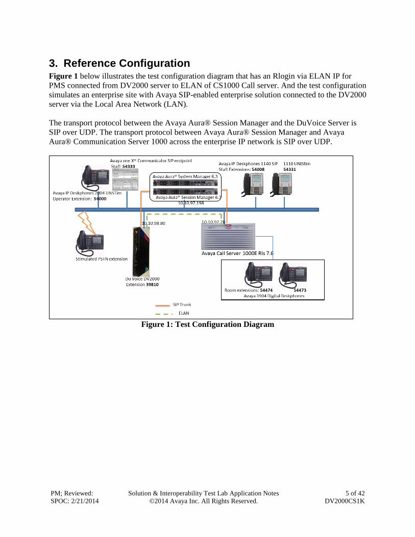
3. Reference Configuration Figure 1 below illustrates the test configuration diagram that has an Rlogin via ELAN IP for
PMS connected from DV2000 server to ELAN of CS1000 Call server. And the test configuration
simulates an enterprise site with Avaya SIP-enabled enterprise solution connected to the DV2000
server via the Local Area Network (LAN).
The transport protocol between the Avaya Aura® Session Manager and the DuVoice Server is
SIP over UDP. The transport protocol between Avaya Aura® Session Manager and Avaya
Aura® Communication Server 1000 across the enterprise IP network is SIP over UDP.
Figure 1: Test Configuration Diagram
PM; Reviewed:
SPOC: 2/21/2014
Solution & Interoperability Test Lab Application Notes
©2014 Avaya Inc. All Rights Reserved.
6 of 42
DV2000CS1K
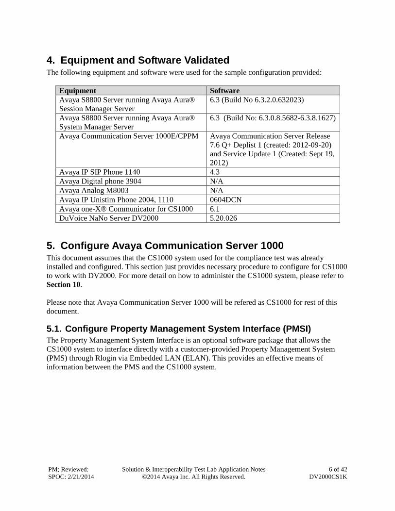
4. Equipment and Software Validated The following equipment and software were used for the sample configuration provided:
Equipment Software
Avaya S8800 Server running Avaya Aura®
Session Manager Server
6.3 (Build No 6.3.2.0.632023)
Avaya S8800 Server running Avaya Aura®
System Manager Server
6.3 (Build No: 6.3.0.8.5682-6.3.8.1627)
Avaya Communication Server 1000E/CPPM Avaya Communication Server Release
7.6 Q+ Deplist 1 (created: 2012-09-20)
and Service Update 1 (Created: Sept 19,
2012)
Avaya IP SIP Phone 1140 4.3
Avaya Digital phone 3904 N/A
Avaya Analog M8003 N/A
Avaya IP Unistim Phone 2004, 1110 0604DCN
Avaya one-X® Communicator for CS1000 6.1
DuVoice NaNo Server DV2000 5.20.026
5. Configure Avaya Communication Server 1000 This document assumes that the CS1000 system used for the compliance test was already
installed and configured. This section just provides necessary procedure to configure for CS1000
to work with DV2000. For more detail on how to administer the CS1000 system, please refer to
Section 10.
Please note that Avaya Communication Server 1000 will be refered as CS1000 for rest of this
document.
5.1. Configure Property Management System Interface (PMSI)
The Property Management System Interface is an optional software package that allows the
CS1000 system to interface directly with a customer-provided Property Management System
(PMS) through Rlogin via Embedded LAN (ELAN). This provides an effective means of
information between the PMS and the CS1000 system.
PM; Reviewed:
SPOC: 2/21/2014
Solution & Interoperability Test Lab Application Notes
©2014 Avaya Inc. All Rights Reserved.
7 of 42
DV2000CS1K
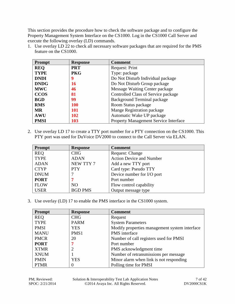
This section provides the procedure how to check the software package and to configure the
Property Management System Interface on the CS1000. Log in the CS1000 Call Server and
execute the following overlay (LD) commands.
1. Use overlay LD 22 to check all necessary software packages that are required for the PMS
feature on the CS1000.
Prompt Response Comment
REQ
TYPE
DNDI
DNDG
MWC
CCOS
BGD
RMS
MR
AWU
PMSI
PRT
PKG
9
16
46
81
99
100
101
102
103
Request: Print
Type: package
Do Not Disturb Individual package
Do Not Disturb Group package
Message Waiting Center package
Controlled Class of Service package
Background Terminal package
Room Status package
Mange Registration package
Automatic Wake UP package
Property Management Service Interface
2. Use overlay LD 17 to create a TTY port number for a PTY connection on the CS1000. This
PTY port was used for DuVoice DV2000 to connect to the Call Server via ELAN.
Prompt Response Comment
REQ
TYPE
ADAN
CTYP
DNUM
PORT
FLOW
USER
CHG
ADAN
NEW TTY 7
PTY
7
7
NO
BGD PMS
Request: Change
Action Device and Number
Add a new TTY port
Card type: Pseudo TTY
Device number for I/O port
Port number
Flow control capability
Output message type
3. Use overlay (LD) 17 to enable the PMS interface in the CS1000 system.
Prompt Response Comment
REQ
TYPE
PMSI
MANU
PMCR
PORT
XTMR
XNUM
PMIN
PTMR
CHG
PARM
YES
PMS1
20
7
2
1
YES
0
Request
System Parameters
Modify properties management system interface
PMS interface
Number of call registers used for PMSI
Port number
PMS acknowledgment time
Number of retransmissions per message
Minor alarm when link is not responding
Polling time for PMSI
PM; Reviewed:
SPOC: 2/21/2014
Solution & Interoperability Test Lab Application Notes
©2014 Avaya Inc. All Rights Reserved.
8 of 42
DV2000CS1K
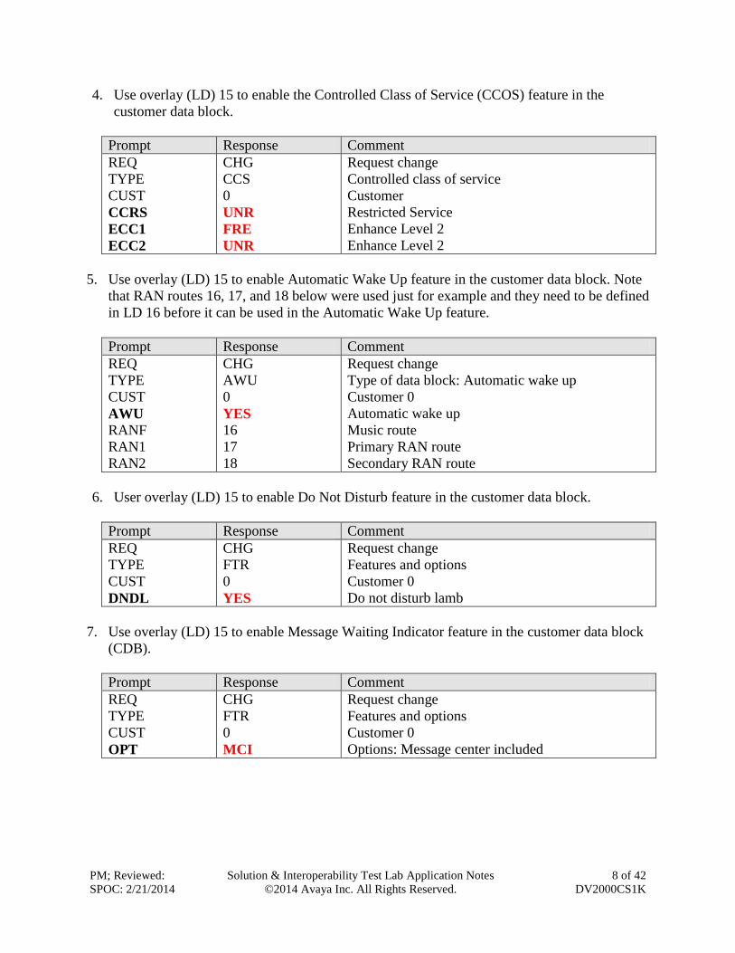
4. Use overlay (LD) 15 to enable the Controlled Class of Service (CCOS) feature in the
customer data block.
Prompt Response Comment
REQ
TYPE
CUST
CCRS
ECC1
ECC2
CHG
CCS
0
UNR
FRE
UNR
Request change
Controlled class of service
Customer
Restricted Service
Enhance Level 2
Enhance Level 2
5. Use overlay (LD) 15 to enable Automatic Wake Up feature in the customer data block. Note
that RAN routes 16, 17, and 18 below were used just for example and they need to be defined
in LD 16 before it can be used in the Automatic Wake Up feature.
Prompt Response Comment
REQ
TYPE
CUST
AWU
RANF
RAN1
RAN2
CHG
AWU
0
YES
16
17
18
Request change
Type of data block: Automatic wake up
Customer 0
Automatic wake up
Music route
Primary RAN route
Secondary RAN route
6. User overlay (LD) 15 to enable Do Not Disturb feature in the customer data block.
Prompt Response Comment
REQ
TYPE
CUST
DNDL
CHG
FTR
0
YES
Request change
Features and options
Customer 0
Do not disturb lamb
7. Use overlay (LD) 15 to enable Message Waiting Indicator feature in the customer data block
(CDB).
Prompt Response Comment
REQ
TYPE
CUST
OPT
CHG
FTR
0
MCI
Request change
Features and options
Customer 0
Options: Message center included
PM; Reviewed:
SPOC: 2/21/2014
Solution & Interoperability Test Lab Application Notes
©2014 Avaya Inc. All Rights Reserved.
9 of 42
DV2000CS1K
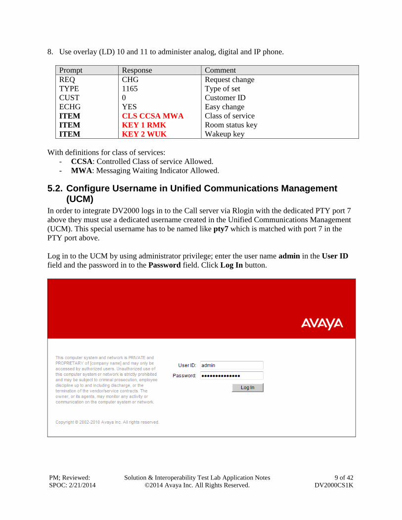
8. Use overlay (LD) 10 and 11 to administer analog, digital and IP phone.
Prompt Response Comment
REQ
TYPE
CUST
ECHG
ITEM
ITEM
ITEM
CHG
1165
0
YES
CLS CCSA MWA
KEY 1 RMK
KEY 2 WUK
Request change
Type of set
Customer ID
Easy change
Class of service
Room status key
Wakeup key
With definitions for class of services:
- CCSA: Controlled Class of service Allowed.
- MWA: Messaging Waiting Indicator Allowed.
5.2. Configure Username in Unified Communications Management (UCM)
In order to integrate DV2000 logs in to the Call server via Rlogin with the dedicated PTY port 7
above they must use a dedicated username created in the Unified Communications Management
(UCM). This special username has to be named like pty7 which is matched with port 7 in the
PTY port above.
Log in to the UCM by using administrator privilege; enter the user name admin in the User ID
field and the password in to the Password field. Click Log In button.
PM; Reviewed:
SPOC: 2/21/2014
Solution & Interoperability Test Lab Application Notes
©2014 Avaya Inc. All Rights Reserved.
10 of 42
DV2000CS1K
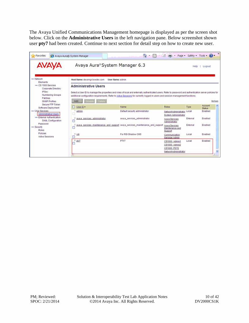
The Avaya Unified Communications Management homepage is displayed as per the screen shot
below. Click on the Administrative Users in the left navigation pane. Below screenshot shown
user pty7 had been created. Continue to next section for detail step on how to create new user.
PM; Reviewed:
SPOC: 2/21/2014
Solution & Interoperability Test Lab Application Notes
©2014 Avaya Inc. All Rights Reserved.
11 of 42
DV2000CS1K
The Administrative Users page is displayed in the right. Click on Add button to add a new user
name (not shown). The Add New Administrative User page is displayed. Enter pty7 in the
User ID field and select Local radio option. Enter a descriptive name in the Full Name field and
a password in the Temporary password and Re-enter password fields. Click on Save and
Continue button to go to next page.
PM; Reviewed:
SPOC: 2/21/2014
Solution & Interoperability Test Lab Application Notes
©2014 Avaya Inc. All Rights Reserved.
12 of 42
DV2000CS1K
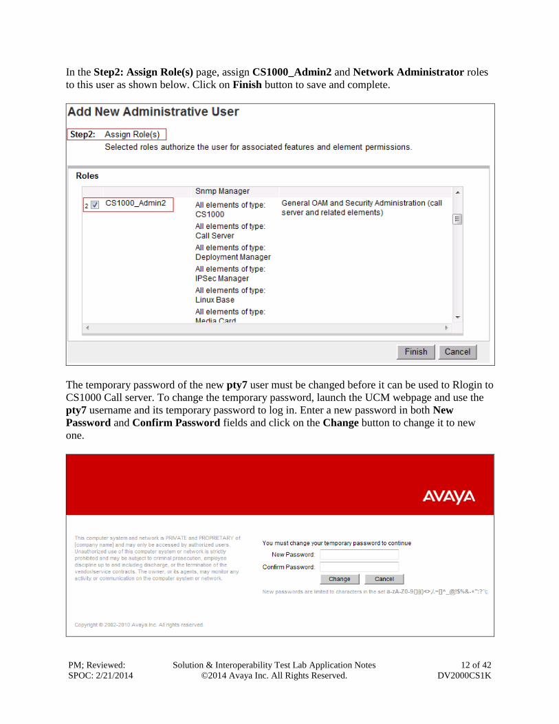
In the Step2: Assign Role(s) page, assign CS1000_Admin2 and Network Administrator roles
to this user as shown below. Click on Finish button to save and complete.
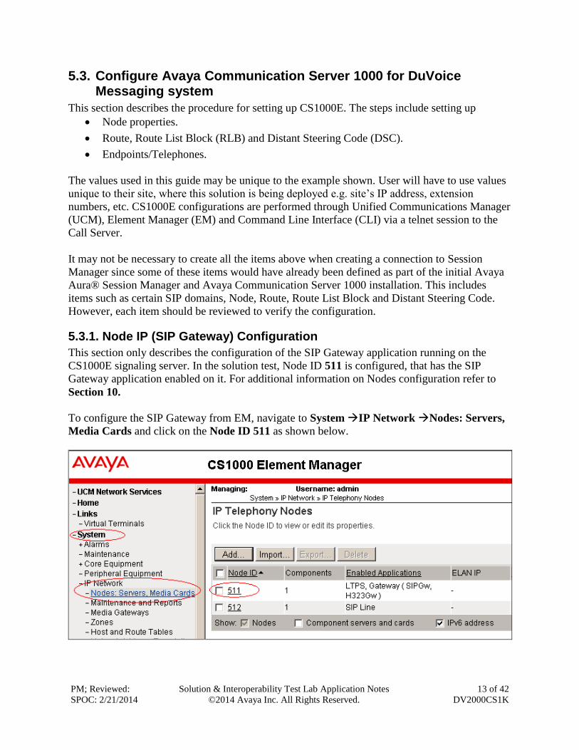
The temporary password of the new pty7 user must be changed before it can be used to Rlogin to
CS1000 Call server. To change the temporary password, launch the UCM webpage and use the
pty7 username and its temporary password to log in. Enter a new password in both New
Password and Confirm Password fields and click on the Change button to change it to new
one.
PM; Reviewed:
SPOC: 2/21/2014
Solution & Interoperability Test Lab Application Notes
©2014 Avaya Inc. All Rights Reserved.
13 of 42
DV2000CS1K
5.3. Configure Avaya Communication Server 1000 for DuVoice Messaging system
This section describes the procedure for setting up CS1000E. The steps include setting up
Node properties.
Route, Route List Block (RLB) and Distant Steering Code (DSC).
Endpoints/Telephones.
The values used in this guide may be unique to the example shown. User will have to use values
unique to their site, where this solution is being deployed e.g. site’s IP address, extension
numbers, etc. CS1000E configurations are performed through Unified Communications Manager
(UCM), Element Manager (EM) and Command Line Interface (CLI) via a telnet session to the
Call Server.
It may not be necessary to create all the items above when creating a connection to Session
Manager since some of these items would have already been defined as part of the initial Avaya
Aura® Session Manager and Avaya Communication Server 1000 installation. This includes
items such as certain SIP domains, Node, Route, Route List Block and Distant Steering Code.
However, each item should be reviewed to verify the configuration.
5.3.1. Node IP (SIP Gateway) Configuration
This section only describes the configuration of the SIP Gateway application running on the
CS1000E signaling server. In the solution test, Node ID 511 is configured, that has the SIP
Gateway application enabled on it. For additional information on Nodes configuration refer to
Section 10.
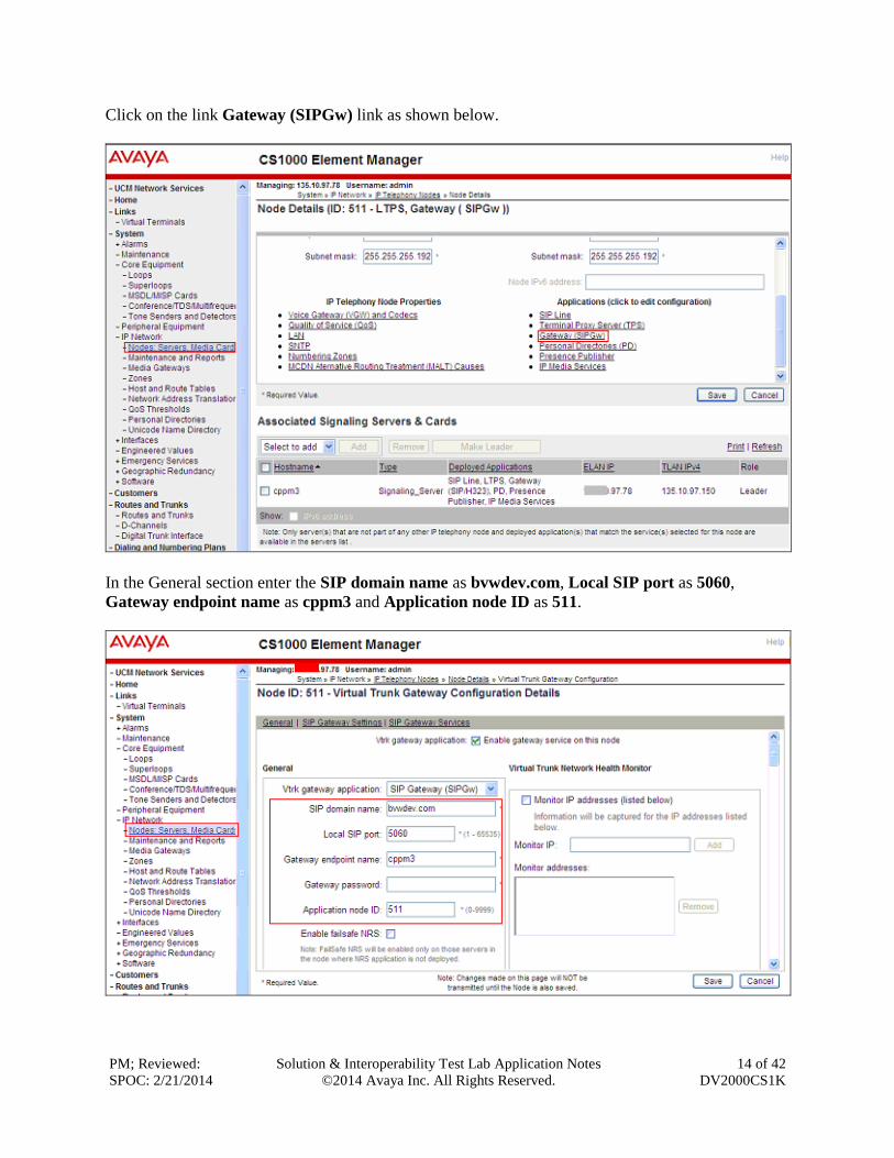
To configure the SIP Gateway from EM, navigate to System IP Network Nodes: Servers,
Media Cards and click on the Node ID 511 as shown below.
PM; Reviewed:
SPOC: 2/21/2014
Solution & Interoperability Test Lab Application Notes
©2014 Avaya Inc. All Rights Reserved.
14 of 42
DV2000CS1K
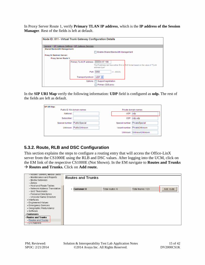
Click on the link Gateway (SIPGw) link as shown below.
In the General section enter the SIP domain name as bvwdev.com, Local SIP port as 5060,
Gateway endpoint name as cppm3 and Application node ID as 511.
PM; Reviewed:
SPOC: 2/21/2014
Solution & Interoperability Test Lab Application Notes
©2014 Avaya Inc. All Rights Reserved.
15 of 42
DV2000CS1K
In Proxy Server Route 1, verify Primary TLAN IP address, which is the IP address of the Session
Manager. Rest of the fields is left at default.
In the SIP URI Map verify the following information: UDP field is configured as udp. The rest of
the fields are left as default.
5.3.2. Route, RLB and DSC Configuration
This section explains the steps to configure a routing entry that will access the Office-LinX
server from the CS1000E using the RLB and DSC values. After logging into the UCM, click on
the EM link of the respective CS1000E (Not Shown). In the EM navigate to Routes and Trunks
Routes and Trunks. Click on Add route.
PM; Reviewed:
SPOC: 2/21/2014
Solution & Interoperability Test Lab Application Notes
©2014 Avaya Inc. All Rights Reserved.
16 of 42
DV2000CS1K
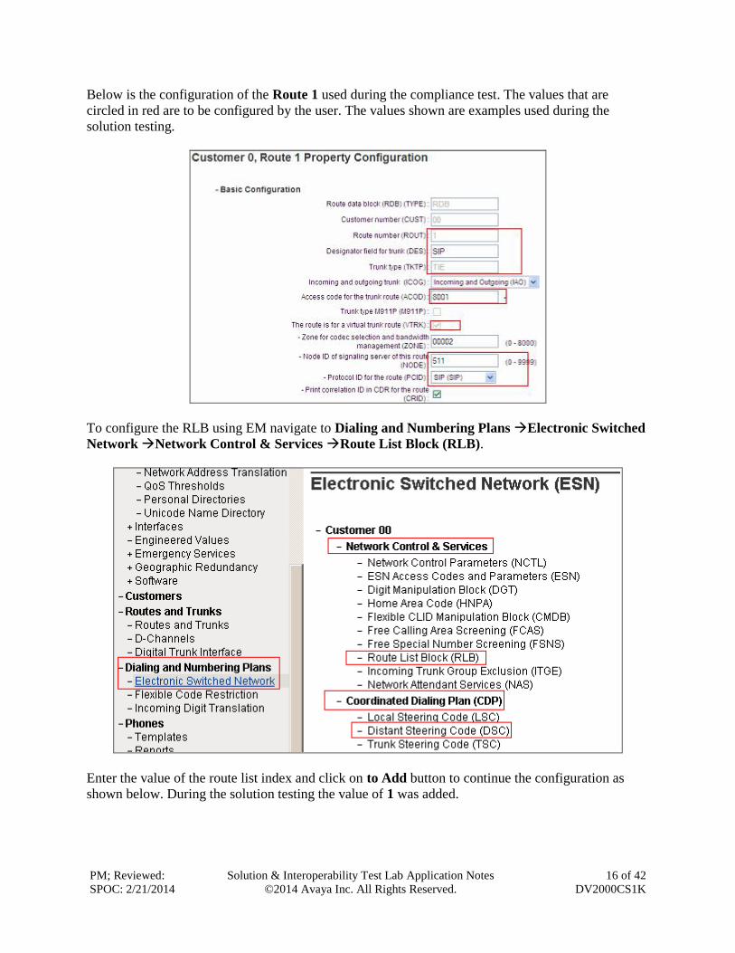
Below is the configuration of the Route 1 used during the compliance test. The values that are
circled in red are to be configured by the user. The values shown are examples used during the
solution testing.
To configure the RLB using EM navigate to Dialing and Numbering Plans Electronic Switched
Network Network Control & Services Route List Block (RLB).
Enter the value of the route list index and click on to Add button to continue the configuration as
shown below. During the solution testing the value of 1 was added.
PM; Reviewed:
SPOC: 2/21/2014
Solution & Interoperability Test Lab Application Notes
©2014 Avaya Inc. All Rights Reserved.
17 of 42
DV2000CS1K
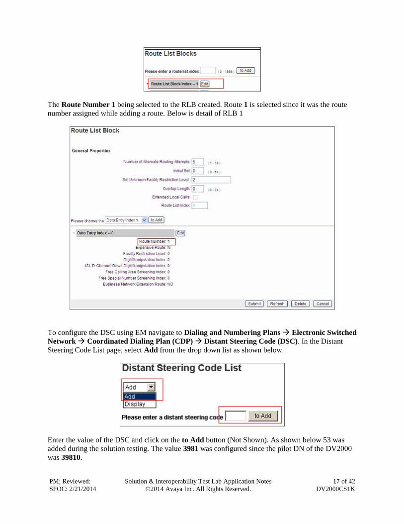
The Route Number 1 being selected to the RLB created. Route 1 is selected since it was the route
number assigned while adding a route. Below is detail of RLB 1
To configure the DSC using EM navigate to Dialing and Numbering Plans Electronic Switched
Network Coordinated Dialing Plan (CDP) Distant Steering Code (DSC). In the Distant
Steering Code List page, select Add from the drop down list as shown below.
Enter the value of the DSC and click on the to Add button (Not Shown). As shown below 53 was
added during the solution testing. The value 3981 was configured since the pilot DN of the DV2000
was 39810.
PM; Reviewed:
SPOC: 2/21/2014
Solution & Interoperability Test Lab Application Notes
©2014 Avaya Inc. All Rights Reserved.
18 of 42
DV2000CS1K
Flexible Length number of digits indentifies length of the directory number (DN). During solution
testing value of 5 was configured.
Route List to be accessed for trunk steering code is selected as 1 from the drop down list. This
value is selected based on the RLB created in above step.
For additional information on Route, RLB and DSC configuration, refer to Section 10 of these
Application Notes.
5.3.3. Endpoint/Telephone Configuration
This section explains the provisioning of an endpoint/telephone for Guest or Staff that was
configured for the solution testing. Endpoint/Telephone can be configured using the CLI of the
CS1000E from overlay LD 11/20. Refer to Section 10 for further information regarding
add/configuration of endpoints/telephones.
Below are values that are shown in red are to be configured by the user. The FDN and HUNT
value of 39810 was used during the solution testing as the pilot DN of the DV2000.
Ld 11
REQ: prt
TYPE: 1165
TN 096 0 00 17
FDN 39810
…
CLS UNR FBA WTA LPR MTD FNA HTA TDD HFA CRPD
MWA LMPN RMMD SMWD AAD IMD XHD IRD NID OLD VCE DRG1
POD SLKD CCSA SWD LNA CNDA
CFTD SFA MRD DDV CNID CDCA MSID DAPA BFED RCBD
ICDD CDMD LLCN MCTD CLBD AUTU
GPUD DPUD DNDA CFXA ARHD CLTD ASCD
CPFA CPTA ABDD CFHD FICD NAID BUZZ AGRD MOAD
UDI RCC HBTD AHD IPND DDGA NAMA MIND PRSD NRWD NRCD NROD
RCO 0
HUNT 39810
…
KEY 00 SCR 54312 0 MARP
CPND
CPND_LANG ROMAN
NAME DN 54312
XPLN 13
DISPLAY_FMT FIRST,LAST
PM; Reviewed:
SPOC: 2/21/2014
Solution & Interoperability Test Lab Application Notes
©2014 Avaya Inc. All Rights Reserved.
19 of 42
DV2000CS1K
6. Configure Session Manager This section provides the procedures for configuring Session Manager as provisioned in the
reference configuration. Session Manager is comprised of two functional components: the
Session Manager server and the System Manager server. All SIP call provisioning for Session
Manager is performed through the System Manager Web interface and is then downloaded into
Session Manager.
The following sections assume that Session Manager and System Manager have been installed
and that network connectivity exists between the two platforms.
In this section, the following topics are discussed:
SIP Domains
Locations: Logical/physical location that can be occupied by SIP Entities.
SIP Entities corresponding to Communication Server 1000 and Session Manager.
Entity Links, which define the SIP trunk parameters used by Session Manager when routing
calls to/from SIP Entities.
Routing Policy, which control call routing between the SIP Entities.
Dial Patterns, which govern to which SIP Entity a call is routed.
It may not be necessary to create all the items above since some of these items would have already
been defined as part of the initial Session Manager installation. This includes items such as certain
SIP domains, locations, SIP entities and Session Manager itself. However, each item should be
reviewed to verify the configuration.
PM; Reviewed:
SPOC: 2/21/2014
Solution & Interoperability Test Lab Application Notes
©2014 Avaya Inc. All Rights Reserved.
20 of 42
DV2000CS1K
6.1. Configure SIP Domain
Launch a web browser, enter “https://<IP address of System Manager>/SMGR” in the URL,
and log in with the appropriate credentials.
Create a SIP domain for each domain for which Avaya Aura® Session Manager will need to be
aware in order to route calls. For the compliance test, this includes the enterprise domain.
Add a domain, navigate to Routing Domains, and click on the New button (not shown) to
create a new SIP Domain. Enter the following values and use default values for remaining
fields: Name: Enter the Authoritative Domain Name, which is bvwdev.com.
Type : Select SIP
Click Commit to save. The following screen shows the Domains page used during the
compliance test.
PM; Reviewed:
SPOC: 2/21/2014
Solution & Interoperability Test Lab Application Notes
©2014 Avaya Inc. All Rights Reserved.
21 of 42
DV2000CS1K
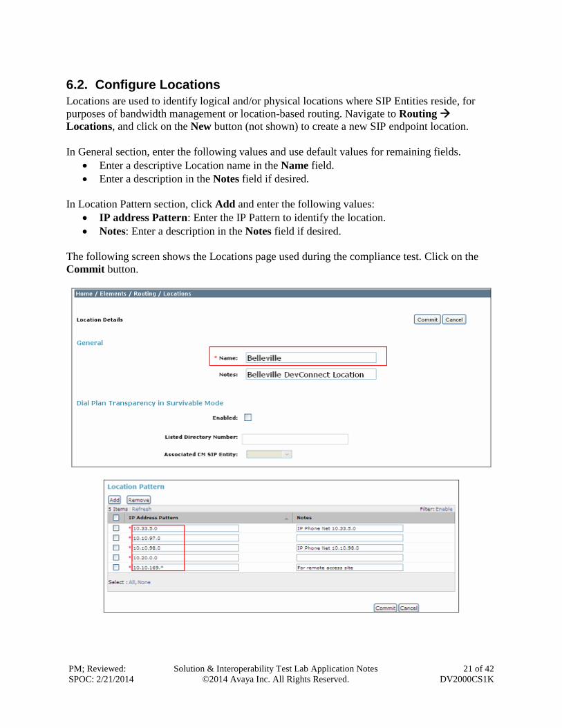
6.2. Configure Locations
Locations are used to identify logical and/or physical locations where SIP Entities reside, for
purposes of bandwidth management or location-based routing. Navigate to Routing
Locations, and click on the New button (not shown) to create a new SIP endpoint location.
In General section, enter the following values and use default values for remaining fields.
Enter a descriptive Location name in the Name field.
Enter a description in the Notes field if desired.
In Location Pattern section, click Add and enter the following values: IP address Pattern: Enter the IP Pattern to identify the location.
Notes: Enter a description in the Notes field if desired.
The following screen shows the Locations page used during the compliance test. Click on the
Commit button.
PM; Reviewed:
SPOC: 2/21/2014
Solution & Interoperability Test Lab Application Notes
©2014 Avaya Inc. All Rights Reserved.
22 of 42
DV2000CS1K
6.3. Configure Adaptation module
Session Manager can be configured with adaptation modules that can modify SIP messages
before or after routing decisions have been made. A generic adaptation module
DigitConversionAdapter supports digit conversion of telephone numbers in specific headers of
SIP messages. Other adaptation modules are built on this generic, and can modify other headers
to permit interoperability with third party SIP products.
To view or change adaptations, select Routing Adaptations. Click on the checkbox
corresponding to the name of an adaptation and Edit to edit an existing adaptation, or the New
button to add an adaptation. Click the Commit button after changes are completed. The
following screen shows a portion of the list of adaptations in the sample configuration. The
adaptations named CS1000 and DuVoice Outgoing Adaptations were configured and used in the
compliance test.
PM; Reviewed:
SPOC: 2/21/2014
Solution & Interoperability Test Lab Application Notes
©2014 Avaya Inc. All Rights Reserved.
23 of 42
DV2000CS1K
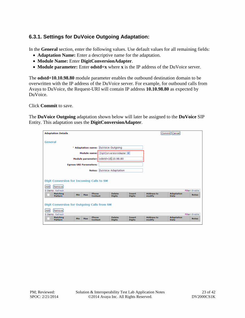
6.3.1. Settings for DuVoice Outgoing Adaptation:
In the General section, enter the following values. Use default values for all remaining fields:
Adaptation Name: Enter a descriptive name for the adaptation.
Module Name: Enter DigitConversionAdapter.
Module parameter: Enter odstd=x where x is the IP address of the DuVoice server.
The odstd=10.10.98.80 module parameter enables the outbound destination domain to be
overwritten with the IP address of the DuVoice server. For example, for outbound calls from
Avaya to DuVoice, the Request-URI will contain IP address 10.10.98.80 as expected by
DuVoice.
Click Commit to save.
The DuVoice Outgoing adaptation shown below will later be assigned to the DuVoice SIP
Entity. This adaptation uses the DigitConversionAdapter.
PM; Reviewed:
SPOC: 2/21/2014
Solution & Interoperability Test Lab Application Notes
©2014 Avaya Inc. All Rights Reserved.
24 of 42
DV2000CS1K
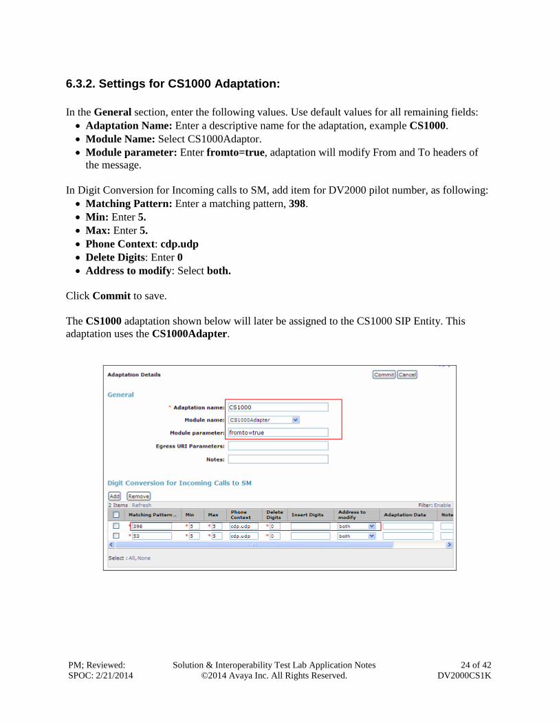
6.3.2. Settings for CS1000 Adaptation:
In the General section, enter the following values. Use default values for all remaining fields:
Adaptation Name: Enter a descriptive name for the adaptation, example CS1000.
Module Name: Select CS1000Adaptor.
Module parameter: Enter fromto=true, adaptation will modify From and To headers of
the message.
In Digit Conversion for Incoming calls to SM, add item for DV2000 pilot number, as following:
Matching Pattern: Enter a matching pattern, 398.
Min: Enter 5.
Max: Enter 5.
Phone Context: cdp.udp
Delete Digits: Enter 0
Address to modify: Select both.
Click Commit to save.
The CS1000 adaptation shown below will later be assigned to the CS1000 SIP Entity. This
adaptation uses the CS1000Adapter.
PM; Reviewed:
SPOC: 2/21/2014
Solution & Interoperability Test Lab Application Notes
©2014 Avaya Inc. All Rights Reserved.
25 of 42
DV2000CS1K
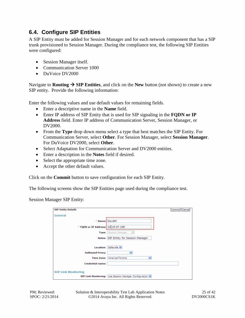
6.4. Configure SIP Entities
A SIP Entity must be added for Session Manager and for each network component that has a SIP
trunk provisioned to Session Manager. During the compliance test, the following SIP Entities
were configured:
Session Manager itself.
Communication Server 1000
DuVoice DV2000
Navigate to Routing SIP Entities, and click on the New button (not shown) to create a new
SIP entity. Provide the following information:
Enter the following values and use default values for remaining fields.
Enter a descriptive name in the Name field.
Enter IP address of SIP Entity that is used for SIP signaling in the FQDN or IP
Address field. Enter IP address of Communication Server, Session Manager, or
DV2000.
From the Type drop down menu select a type that best matches the SIP Entity. For
Communication Server, select Other. For Session Manager, select Session Manager.
For DuVoice DV2000, select Other.
Select Adaptation for Communication Server and DV2000 entities.
Enter a description in the Notes field if desired.
Select the appropriate time zone.
Accept the other default values.
Click on the Commit button to save configuration for each SIP Entity.
The following screens show the SIP Entities page used during the compliance test.
Session Manager SIP Entity:
PM; Reviewed:
SPOC: 2/21/2014
Solution & Interoperability Test Lab Application Notes
©2014 Avaya Inc. All Rights Reserved.
26 of 42
DV2000CS1K
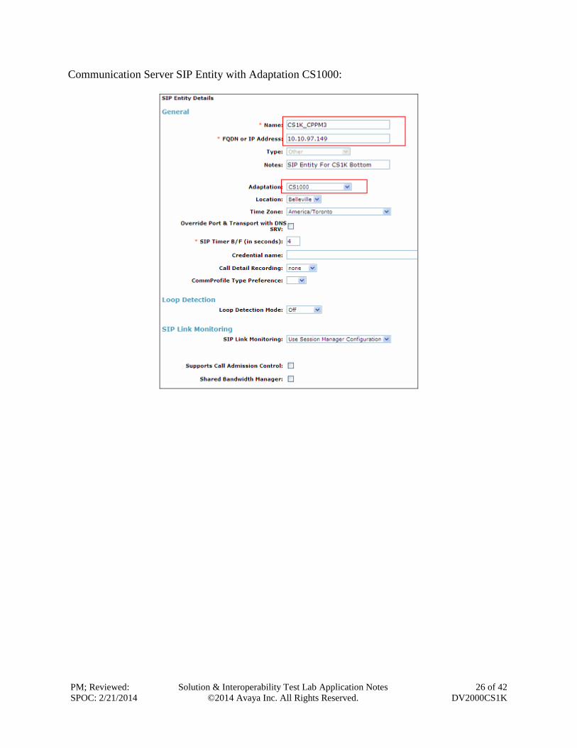
Communication Server SIP Entity with Adaptation CS1000:
PM; Reviewed:
SPOC: 2/21/2014
Solution & Interoperability Test Lab Application Notes
©2014 Avaya Inc. All Rights Reserved.
27 of 42
DV2000CS1K
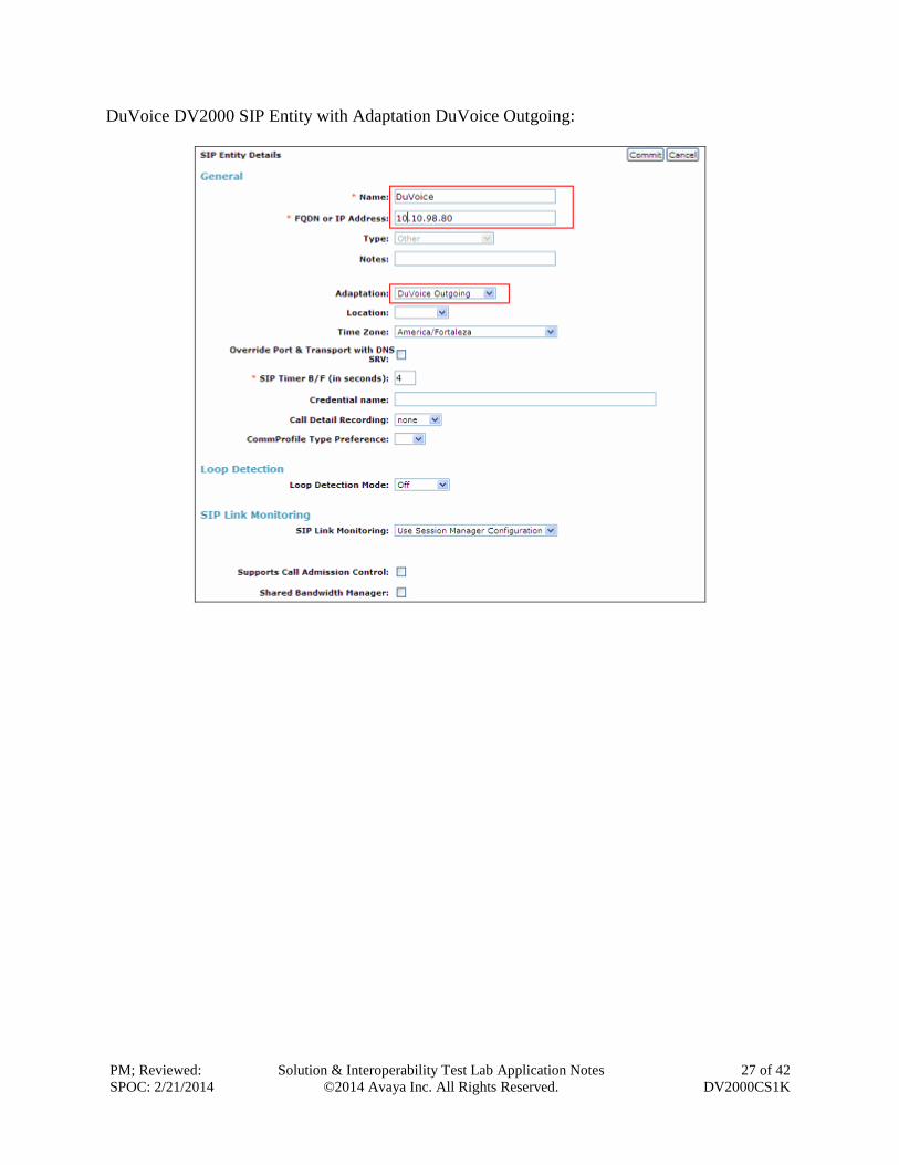
DuVoice DV2000 SIP Entity with Adaptation DuVoice Outgoing:
PM; Reviewed:
SPOC: 2/21/2014
Solution & Interoperability Test Lab Application Notes
©2014 Avaya Inc. All Rights Reserved.
28 of 42
DV2000CS1K
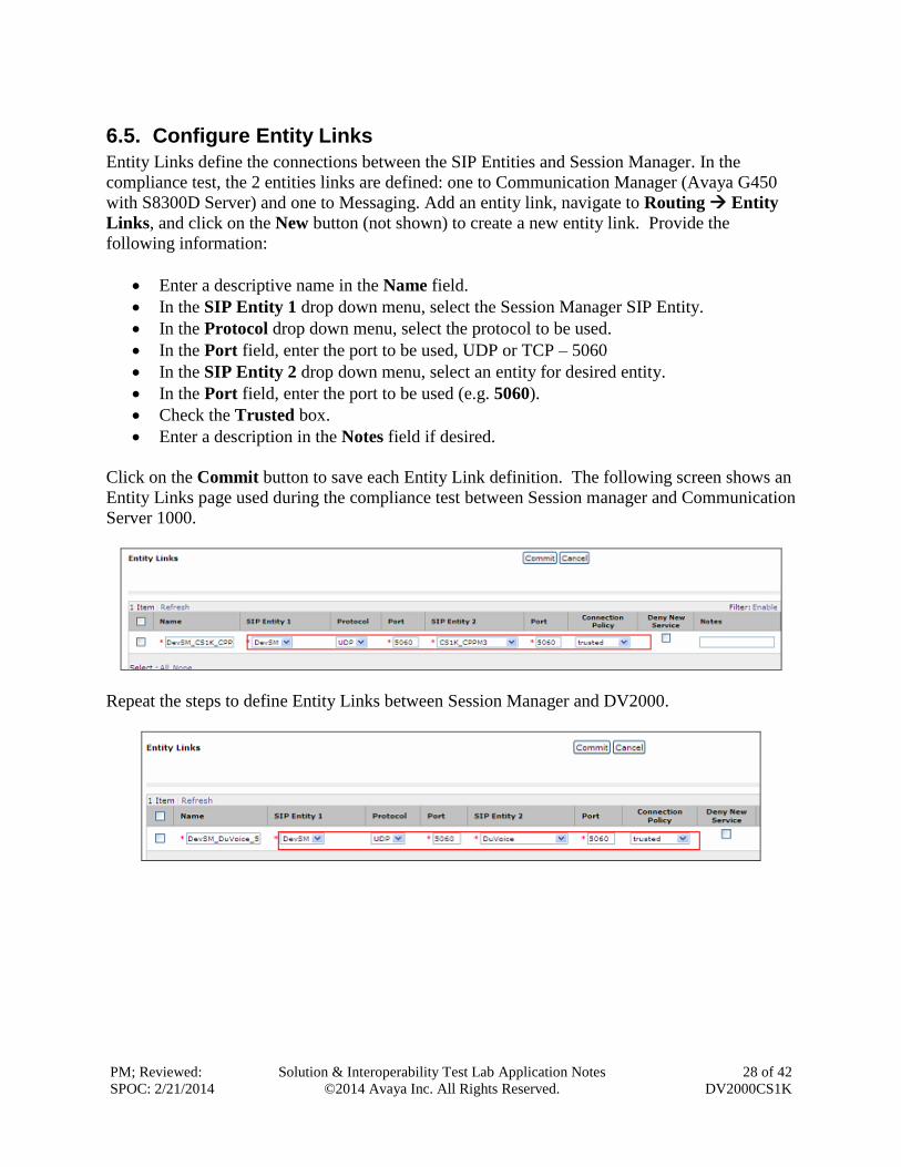
6.5. Configure Entity Links
Entity Links define the connections between the SIP Entities and Session Manager. In the
compliance test, the 2 entities links are defined: one to Communication Manager (Avaya G450
with S8300D Server) and one to Messaging. Add an entity link, navigate to Routing Entity
Links, and click on the New button (not shown) to create a new entity link. Provide the
following information:
Enter a descriptive name in the Name field.
In the SIP Entity 1 drop down menu, select the Session Manager SIP Entity.
In the Protocol drop down menu, select the protocol to be used.
In the Port field, enter the port to be used, UDP or TCP – 5060
In the SIP Entity 2 drop down menu, select an entity for desired entity.
In the Port field, enter the port to be used (e.g. 5060).
Check the Trusted box.
Enter a description in the Notes field if desired.
Click on the Commit button to save each Entity Link definition. The following screen shows an
Entity Links page used during the compliance test between Session manager and Communication
Server 1000.
Repeat the steps to define Entity Links between Session Manager and DV2000.
PM; Reviewed:
SPOC: 2/21/2014
Solution & Interoperability Test Lab Application Notes
©2014 Avaya Inc. All Rights Reserved.
29 of 42
DV2000CS1K
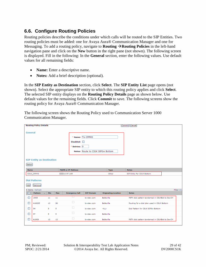
6.6. Configure Routing Policies
Routing policies describe the conditions under which calls will be routed to the SIP Entities. Two
routing policies must be added: one for Avaya Aura® Communication Manager and one for
Messaging. To add a routing policy, navigate to Routing Routing Policies in the left-hand
navigation pane and click on the New button in the right pane (not shown). The following screen
is displayed. Fill in the following: In the General section, enter the following values. Use default
values for all remaining fields:
Name: Enter a descriptive name.
Notes: Add a brief description (optional).
In the SIP Entity as Destination section, click Select. The SIP Entity List page opens (not
shown). Select the appropriate SIP entity to which this routing policy applies and click Select.
The selected SIP entity displays on the Routing Policy Details page as shown below. Use
default values for the remaining fields. Click Commit to save. The following screens show the
routing policy for Avaya Aura® Communication Manager.
The following screen shows the Routing Policy used to Communication Server 1000
Communication Manager.
PM; Reviewed:
SPOC: 2/21/2014
Solution & Interoperability Test Lab Application Notes
©2014 Avaya Inc. All Rights Reserved.
30 of 42
DV2000CS1K
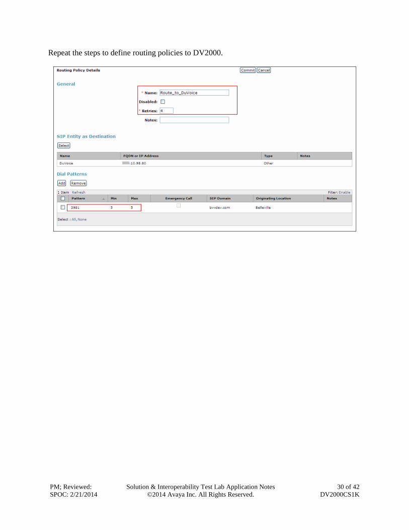
Repeat the steps to define routing policies to DV2000.
PM; Reviewed:
SPOC: 2/21/2014
Solution & Interoperability Test Lab Application Notes
©2014 Avaya Inc. All Rights Reserved.
31 of 42
DV2000CS1K
6.7. Configure Dial Patterns
Dial Patterns define digit strings to be matched for inbound and outbound calls. In addition, the
domain in the request URI is also examined. In the compliance test, the following dial patterns
are defined from Session Manager.
54xxx – SIP endpoints in Avaya CS1000
39810 –DV2000 Pilot Number.
To add a Dial Pattern, select Routing Dial Patterns, and click on the New button (not shown)
on the right. During the compliance test, 5 digit dial plan was utilized. Provide the following
information:
In the General section, enter the following values. Use default values for all remaining fields:
Pattern: Enter a dial string that will be matched against the Request-URI of the call.
Min: Enter a minimum length used in the match criteria.
Max: Enter a maximum length used in the match criteria.
SIP Domain: Enter the destination domain used in the match criteria.
Notes: Add a brief description (optional).
In the Originating Locations and Routing Policies section, click Add. From the Originating
Locations and Routing Policy List that appears (not shown), select the appropriate originating
location for use in the match criteria. Lastly, select the routing policy from the list that will be
used to route calls that match the specified criteria. Click Select.
Default values can be used for the remaining fields. Click Commit to save. See screenshot in
Section 6.6 for detail of dial pattern for each SIP entity.
PM; Reviewed:
SPOC: 2/21/2014
Solution & Interoperability Test Lab Application Notes
©2014 Avaya Inc. All Rights Reserved.
32 of 42
DV2000CS1K
7. Configure DuVoice DV2000 Application This section describes details the essential portion of the DuVoice DV2000 configuration to
interoperate with Avaya Session Manager and Avaya Communication Server 1000. These
Application Notes assume that the DuVoice DV2000 has already been properly installed by
DuVoice services personnel.
At the time of taking the screenshot all setup has been in place. This section will capture the detail of
the configuration had been in place on DV20000 for review.
PM; Reviewed:
SPOC: 2/21/2014
Solution & Interoperability Test Lab Application Notes
©2014 Avaya Inc. All Rights Reserved.
33 of 42
DV2000CS1K
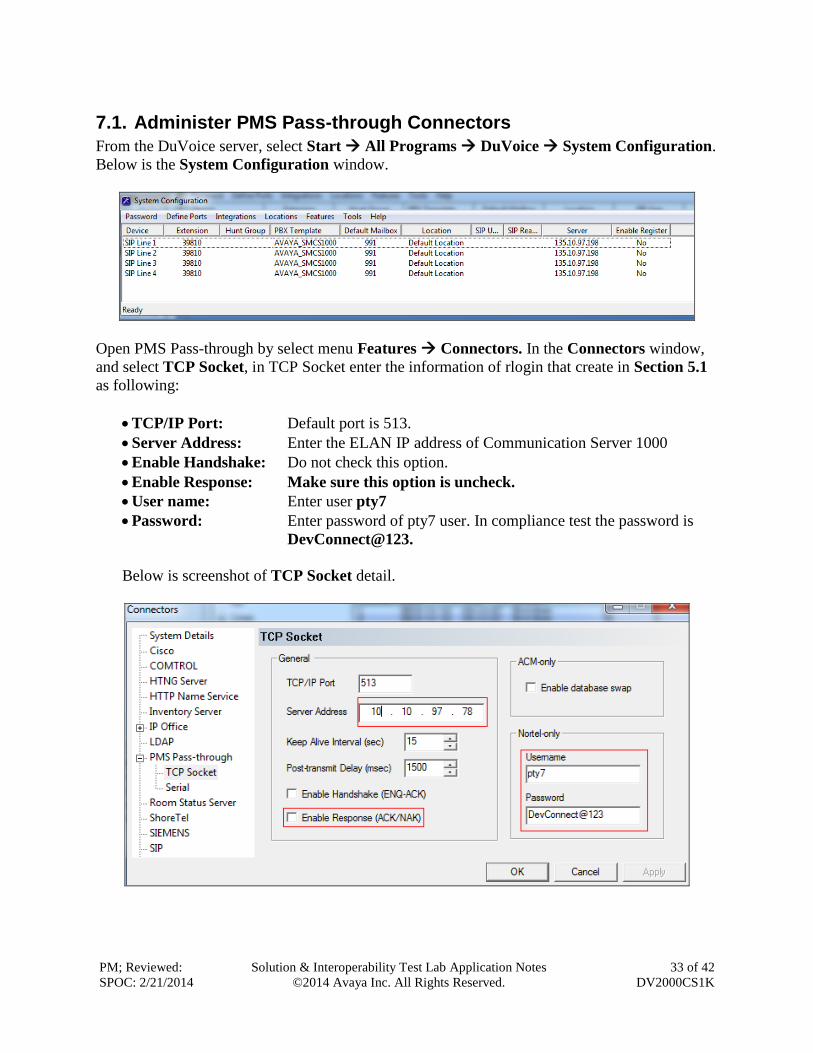
7.1. Administer PMS Pass-through Connectors
From the DuVoice server, select Start All Programs DuVoice System Configuration.
Below is the System Configuration window.
Open PMS Pass-through by select menu Features Connectors. In the Connectors window,
and select TCP Socket, in TCP Socket enter the information of rlogin that create in Section 5.1
as following:
TCP/IP Port: Default port is 513.
Server Address: Enter the ELAN IP address of Communication Server 1000
Enable Handshake: Do not check this option.
Enable Response: Make sure this option is uncheck.
User name: Enter user pty7
Password: Enter password of pty7 user. In compliance test the password is
DevConnect@123.
Below is screenshot of TCP Socket detail.
PM; Reviewed:
SPOC: 2/21/2014
Solution & Interoperability Test Lab Application Notes
©2014 Avaya Inc. All Rights Reserved.
34 of 42
DV2000CS1K
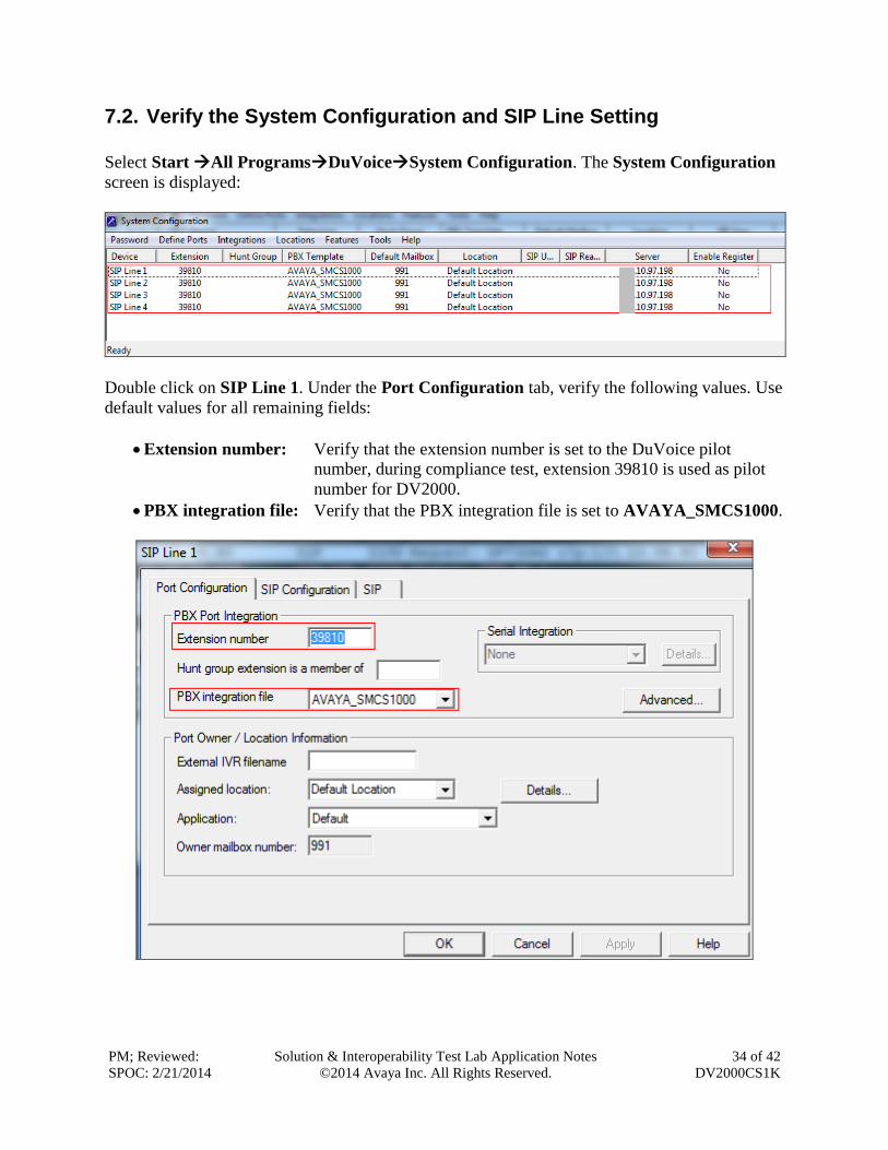
7.2. Verify the System Configuration and SIP Line Setting
Select Start All ProgramsDuVoiceSystem Configuration. The System Configuration
screen is displayed:
Double click on SIP Line 1. Under the Port Configuration tab, verify the following values. Use
default values for all remaining fields:
Extension number: Verify that the extension number is set to the DuVoice pilot
number, during compliance test, extension 39810 is used as pilot
number for DV2000.
PBX integration file: Verify that the PBX integration file is set to AVAYA_SMCS1000.
PM; Reviewed:
SPOC: 2/21/2014
Solution & Interoperability Test Lab Application Notes
©2014 Avaya Inc. All Rights Reserved.
35 of 42
DV2000CS1K
Under the SIP tab verify SIP setting:
Server address: Verify that the Registrar address is set to the IP address of Session
Manager.
Port: 5060
Dialogic IP Address: Verify it set to IP address of DuVoice device.
SIP trunk: Verify that SIP Trunk is not checked.
Leave other fields as default.
Repeat this section for each remaining Voice Port Number 2-4 for the sample configuration.
PM; Reviewed:
SPOC: 2/21/2014
Solution & Interoperability Test Lab Application Notes
©2014 Avaya Inc. All Rights Reserved.
36 of 42
DV2000CS1K
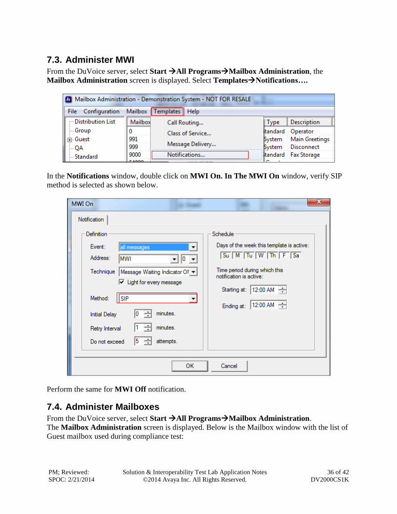
7.3. Administer MWI
From the DuVoice server, select Start All ProgramsMailbox Administration, the
Mailbox Administration screen is displayed. Select TemplatesNotifications….
In the Notifications window, double click on MWI On. In The MWI On window, verify SIP
method is selected as shown below.
Perform the same for MWI Off notification.
7.4. Administer Mailboxes
From the DuVoice server, select Start All ProgramsMailbox Administration.
The Mailbox Administration screen is displayed. Below is the Mailbox window with the list of
Guest mailbox used during compliance test:
PM; Reviewed:
SPOC: 2/21/2014
Solution & Interoperability Test Lab Application Notes
©2014 Avaya Inc. All Rights Reserved.
37 of 42
DV2000CS1K
To add new mailbox, right click on the Mailbox window, the Create Mailbox screen is
displayed next. For Mailbox Number, enter the first voicemail user extension, in this case
“54333” was created. For Mailbox Type, select “Guest” for guest users and “Standard” for front
desk and staff users.
PM; Reviewed:
SPOC: 2/21/2014
Solution & Interoperability Test Lab Application Notes
©2014 Avaya Inc. All Rights Reserved.
38 of 42
DV2000CS1K
The Mailbox 54333 screen is displayed next. Enter desired values for Password, First Name,
and Last Name, and retain the default values in the remaining fields.
Repeat this section for all voicemail users.
7.5. Verify Port Activity
From the DuVoice server, select Start All Programs Activity Monitor. The Activity
Monitor screen is displayed. Verify that all configured ports are IDLE and ready to accept calls.
PM; Reviewed:
SPOC: 2/21/2014
Solution & Interoperability Test Lab Application Notes
©2014 Avaya Inc. All Rights Reserved.
39 of 42
DV2000CS1K
8. Verification Steps
8.1. Verify Property Management System Interface
The following steps might be used to verify the connection between Avaya CS1000 switch and
DuVoice DV2000.
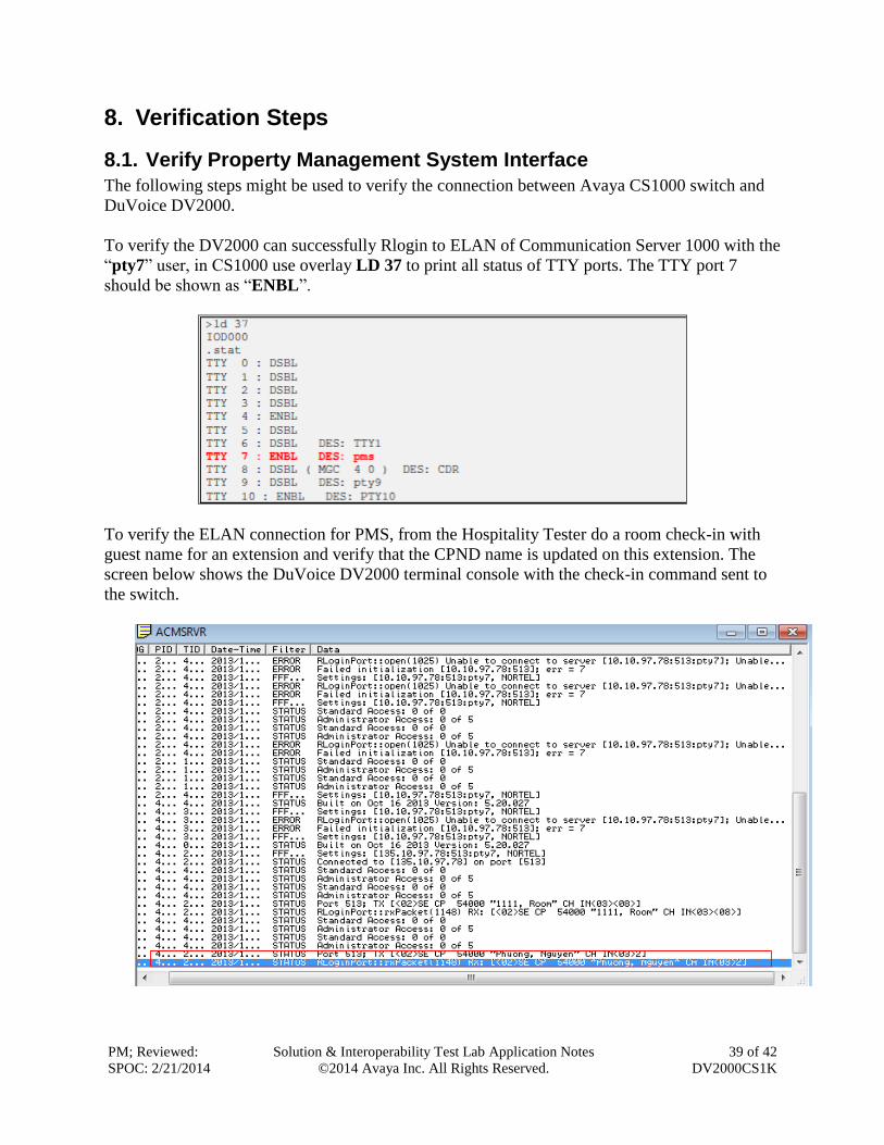
To verify the DV2000 can successfully Rlogin to ELAN of Communication Server 1000 with the
“pty7” user, in CS1000 use overlay LD 37 to print all status of TTY ports. The TTY port 7
should be shown as “ENBL”.
To verify the ELAN connection for PMS, from the Hospitality Tester do a room check-in with
guest name for an extension and verify that the CPND name is updated on this extension. The
screen below shows the DuVoice DV2000 terminal console with the check-in command sent to
the switch.
PM; Reviewed:
SPOC: 2/21/2014
Solution & Interoperability Test Lab Application Notes
©2014 Avaya Inc. All Rights Reserved.
40 of 42
DV2000CS1K
Verify Automated Attendant features: Place an incoming trunk call to the DV2000 pilot number, when asked enter a valid guest
extension (defined in the DuVoice server) to be transferred to. Verify that the transfer
takes place, ring back and speech path in both directions.
Verify Voice Mail features:
Place a call to reach a guest, do not answer the call. Verify the caller hears the system
greeting, leave a voice message. Verify the MWI is turned on at the guest telephone.
Make a call from the guest extension to the hunt group pilot number, Verify the greeting
is played and that the message can be retrieved. Verify the MWI is turned off.
Verify Wakeup call feature:
From a guest extension call the DV2000 pilot number to schedule a wakeup call. Verify
that the wakeup call takes place at the scheduled time.
8.2. Verify SIP Entity Links
Navigate to Elements Session Manager System Status SIP Entity Monitoring (not
shown) to view more detailed status information for one of the SIP Entity Links.
Select the SIP Entity for DevACEsrv from the All Monitored SIP Entities table (not shown) to
open the SIP Entity, Entity Link Connection Status page.
In the All Entity Links to SIP Entity: DuVoice table, verify the Conn. Status for the link is
“Up” as shown below.
9. Conclusion These Application Notes describe the procedures for configuring DuVoice DV2000 to
interoperate with Session Manager and Communication Server 1000. All interoperability
compliance test cases executed against such a configuration were completed successfully.
10. Additional References Product documentation for Avaya products may be found at http://support.avaya.com
PM; Reviewed:
SPOC: 2/21/2014
Solution & Interoperability Test Lab Application Notes
©2014 Avaya Inc. All Rights Reserved.
41 of 42
DV2000CS1K
[1] Hospitality Features Fundamentals, Release 7.0, Issue 04.01, Date June 2010.
[3] Software Input Output Reference — Administration Avaya Communication Server 1000,
Release 7.6, Issue 04.02, Date Apr 04, 2013.
Product documentation for DuVoice DV2000 products may be found at
PM; Reviewed:
SPOC: 2/21/2014
Solution & Interoperability Test Lab Application Notes
©2014 Avaya Inc. All Rights Reserved.
42 of 42
DV2000CS1K
©2014 Avaya Inc. All Rights Reserved.
Avaya and the Avaya Logo are trademarks of Avaya Inc. All trademarks identified by ® and
™ are registered trademarks or trademarks, respectively, of Avaya Inc. All other trademarks
are the property of their respective owners. The information provided in these Application
Notes is subject to change without notice. The configurations, technical data, and
recommendations provided in these Application Notes are believed to be accurate and
dependable, but are presented without express or implied warranty. Users are responsible for
their application of any products specified in these Application Notes.
Please e-mail any questions or comments pertaining to these Application Notes along with the
full title name and filename, located in the lower right corner, directly to the Avaya
DevConnect Program at [email protected].