John-Paul Latham and Jiansheng Xiang 1 Application of the finite-discrete element method to dynamic stress development in armour units and armour layers John-Paul Latham and Jiansheng Xiang Applied Modelling and Computation Group, Department of Earth Science and Engineering, Imperial College London. Introduction Policy makers formulating adaptation strategies in response to climate change will increasingly turn to coastal engineers for practical solutions to ‘hold the line’ where it is deemed necessary to protect communities and infrastructure. A popular design approach is protection with “rubble mound” armour layers consisting of thousands of quarried rocks and/or concrete units. They are placed by crane or excavator in a manner to encourage interlocking with neighbouring units. This has proven to be a very adaptable design approach. However, further design optimisation remains hampered by a lack of understanding of forces and stresses especially those during disturbance by storm waves. In exposed oceans, rock pieces above 10-20 tonnes are often needed but are difficult to source locally as nearby quarries are unlikely to produce such large blocks in the abundance needed. Concrete units most commonly used instead of rock armour have masses of tens of tonnes. Many different specially-shaped units have been invented such as Tetrapod, Dolos, Accropode™, Coreloc®, X-bloc® and a recent addition, the Cubipod (Fig. 1). When cast in concrete, such units have been shown to interlock well but may be prone to breakage with movements and impacts during construction, storms or by fatigue mechanisms. Thousands of such units may be cast and placed in one breakwater. The relatively low tensile strength of concrete has been a concern when using slender interlocking type units with concave corners or legs. Unit designs have therefore evolved to chunkier forms with less severe concave corners hence reducing the probability of significant tensile stress development. Concerns over durability of reinforced concrete in marine environments are clearly well founded and experts cannot agree on the cost effectiveness of the multi-million pound investment needed to boost tensile strengths and reinforce the thousands of units typically involved in deep water structures. In extreme cases where > 50- 100 tonne units are required, cube-like blocks have been a favoured option (as they greatly limit tensile stresses e.g. associated with bending moments). They have been applied widely on Spain’s Atlantic coast breakwaters in deeper waters (Guillén, 2009). It has sometimes been claimed that cube-like blocks tend to self-organise into block-work arrays giving lower porosity, high material costs and high overtopping locally. This concern was the motivation behind the invention of perhaps the most recent new shaped unit – the Cubipod (see Gomez-Martin and Medina 2007). How the various shaped units fulfil their function in terms of mechanics is an intriguing question. Towards more fundamental design approaches for rubble mounds Modern civil engineering is founded on determining imposed design loads and deriving robust solutions where the optimised structure has the necessary resistance to withstand the
Transcript
John-Paul Latham and Jiansheng Xiang 1
Application of the finite-discrete element method to dynamic stress development in armour units and armour layers John-Paul Latham and Jiansheng Xiang Applied Modelling and Computation Group, Department of Earth Science and Engineering, Imperial College London. Introduction Policy makers formulating adaptation strategies in response to climate change will increasingly turn to coastal engineers for practical solutions to ‘hold the line’ where it is deemed necessary to protect communities and infrastructure. A popular design approach is protection with “rubble mound” armour layers consisting of thousands of quarried rocks and/or concrete units. They are placed by crane or excavator in a manner to encourage interlocking with neighbouring units. This has proven to be a very adaptable design approach. However, further design optimisation remains hampered by a lack of understanding of forces and stresses especially those during disturbance by storm waves. In exposed oceans, rock pieces above 10-20 tonnes are often needed but are difficult to source locally as nearby quarries are unlikely to produce such large blocks in the abundance needed. Concrete units most commonly used instead of rock armour have masses of tens of tonnes. Many different specially-shaped units have been invented such as Tetrapod, Dolos, Accropode™, Coreloc®, X-bloc® and a recent addition, the Cubipod (Fig. 1). When cast in concrete, such units have been shown to interlock well but may be prone to breakage with movements and impacts during construction, storms or by fatigue mechanisms. Thousands of such units may be cast and placed in one breakwater. The relatively low tensile strength of concrete has been a concern when using slender interlocking type units with concave corners or legs. Unit designs have therefore evolved to chunkier forms with less severe concave corners hence reducing the probability of significant tensile stress development. Concerns over durability of reinforced concrete in marine environments are clearly well founded and experts cannot agree on the cost effectiveness of the multi-million pound investment needed to boost tensile strengths and reinforce the thousands of units typically involved in deep water structures. In extreme cases where > 50-100 tonne units are required, cube-like blocks have been a favoured option (as they greatly limit tensile stresses e.g. associated with bending moments). They have been applied widely on Spain’s Atlantic coast breakwaters in deeper waters (Guillén, 2009). It has sometimes been claimed that cube-like blocks tend to self-organise into block-work arrays giving lower porosity, high material costs and high overtopping locally. This concern was the motivation behind the invention of perhaps the most recent new shaped unit – the Cubipod (see Gomez-Martin and Medina 2007). How the various shaped units fulfil their function in terms of mechanics is an intriguing question. Towards more fundamental design approaches for rubble mounds Modern civil engineering is founded on determining imposed design loads and deriving robust solutions where the optimised structure has the necessary resistance to withstand the
John-Paul Latham and Jiansheng Xiang 2
stresses generated. By contrast, the design of “rubble mound” structures is based on empirical methods little advanced since the 1980’s. The problem has been one of determining prototype stresses and potential breakages in gigantic unit packs, a problem which has remained unsolved, in spite of considerable research efforts e.g. see the monograph by Hans Burcharth (1993). Rubble mound designs are built with minimal understanding of contact forces active during wave loading. The structure’s intended resistance to disturbing loads is not even an explicit part of the design calculation. This is in stark contrast to, for example, bridge design and civil engineering as a whole. With global warming, the growing problem is that existing and future coastal structures may continue to be significantly under-optimized for the site conditions they are designed for. At the under-designed extreme, units either fail to stay well-interlocked before (e.g. toe and foundation problems) and during storm action, leading to dramatic breakwater failures at vast expense e.g. see the well-documented failure of Sines, (Baird et al 1984; Lillevang et al. 1984; Edge, et al. 1982) but also Crescent City, Richard’s Bay, Port Arzew El Djedid Breakwaters and more recent examples cited by Maddrell (2005) where armour units may become broken in pieces with the potential to act as battering rams. Alternatively, armour layers may be substantially over-designed with excessively massive bulky or cube-like units deployed in double layers, unnecessary cement consumption, carbon footprint and cost.
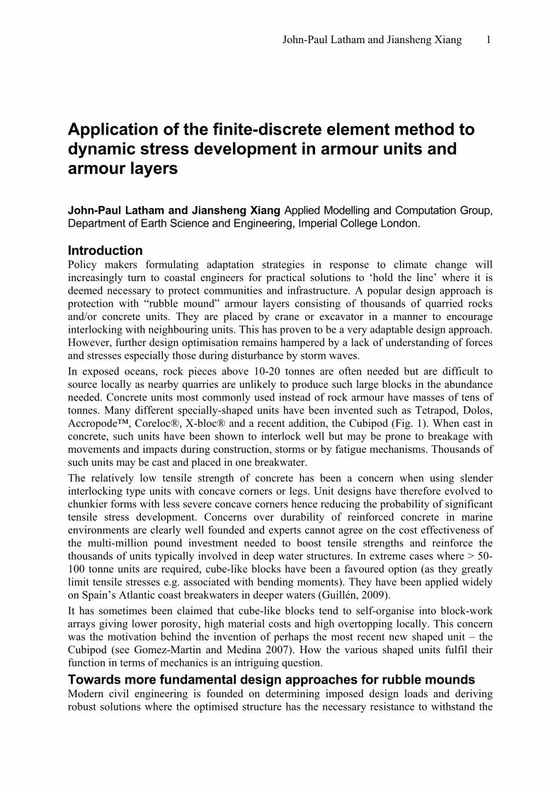
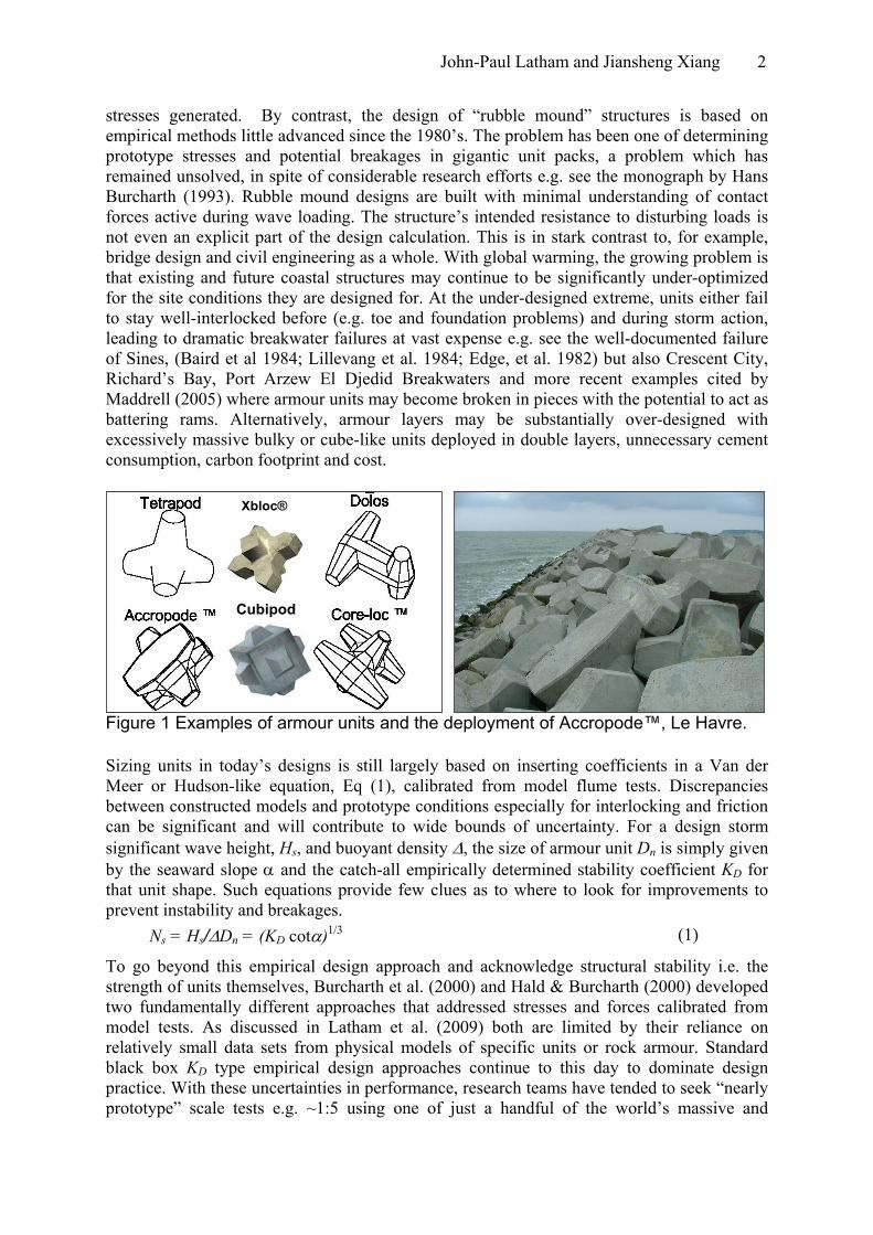
Figure 1 Examples of armour units and the deployment of Accropode™, Le Havre.
Cubipod
Xbloc®
Sizing units in today’s designs is still largely based on inserting coefficients in a Van der Meer or Hudson-like equation, Eq (1), calibrated from model flume tests. Discrepancies between constructed models and prototype conditions especially for interlocking and friction can be significant and will contribute to wide bounds of uncertainty. For a design storm significant wave height, Hs, and buoyant density Δ, the size of armour unit Dn is simply given by the seaward slope α and the catch-all empirically determined stability coefficient KD for that unit shape. Such equations provide few clues as to where to look for improvements to prevent instability and breakages.
Ns = Hs/ΔDn = (KD cotα)1/3 (1)
To go beyond this empirical design approach and acknowledge structural stability i.e. the strength of units themselves, Burcharth et al. (2000) and Hald & Burcharth (2000) developed two fundamentally different approaches that addressed stresses and forces calibrated from model tests. As discussed in Latham et al. (2009) both are limited by their reliance on relatively small data sets from physical models of specific units or rock armour. Standard black box KD type empirical design approaches continue to this day to dominate design practice. With these uncertainties in performance, research teams have tended to seek “nearly prototype” scale tests e.g. ~1:5 using one of just a handful of the world’s massive and
John-Paul Latham and Jiansheng Xiang 3
expensive-to-operate wave flumes to validate research results based on standard small scale (~1:40) laboratory tests. Through anecdotal experience of breakages and back analysis of damage in storms, designers have built up confidence in design methods. They have also sought evidence from monitoring of built structures. Observations of in-service performance has been achieved by placing instrumented concrete armour units on breakwaters and observing long-term movement and performance (Mayrick and Melby 2005) and conducting drop and pendulum breakage tests at full-scale Burcharth (1981), Melby and Turk, (1997), Muttray et al. (2005), but in spite of Burcharth’s (1993) treatise on the subject, convincing the designer of a large breakwater that the chosen armour unit system has sufficient strength remains problematic. Zwamborn and Phelp (1988) by-passed stress determination and performed calibration experiments to measured the degree of cushioning (by measuring deceleration). Test units were experimentally toppled and impacted against the neighbouring units in the surrounding armour pack at full scale on site. Full-scale fall-tests where blocks topple onto a deformable ‘metal frame cushioning device’ which they had calibrated to reproduce the cushioning deformation equivalent to breakwater conditions could then be presented to designers. It is probably reasonable to say these ingenious tests, restricted to Dolos units, were still not entirely convincing. Whereas quite a lot is known about stresses in Dolos, new unit designs where their effectiveness is hard to prove beforehand, are continually being invented. Their design involves many considerations; experience, understanding of structural form, wave/armour processes, constructability all playing a large part. Understanding why a unit should be especially successful in terms of interlocking and resisting breakage under hydraulic and structural loads is hard to pin down. The combination of Hudson-type empirical testing for hydraulic stability backed up by dramatic images of drop and impact tests (typically with poorly controlled and un-quantified anvil absorption) is often the main available evidence the designer of a new unit has to offer the coastal engineer. When in addition, results for a new concrete unit include experimental model pull-out tests, quasi-static and rapid loading FEM stress analysis for a range of relevant severe boundary constraints, a better impression of likely performance can be presented (Muttray et al. 2005). However, amplified static and dynamic tensile stresses involved in an armour layer system with disturbance and impacts should concern the designer even more and this cannot be presented in most available FEM modelling codes.
Given this picture, it is not surprising that coupled numerical models that handle the key hydraulic, structural and geotechnical interactions are now considered urgent technologies for the early 21st century, to reduce reliance on physical tests and provide a more detailed understanding of hydraulic loads, unit stresses, potential breakages and underlying coastal processes. This is an active research area for wave-structure modelling groups in Denmark, France, Japan, Netherlands, Norway, Spain, USA, and UK. For all of them, a critically important task in building this technology is to develop and validate numerical models of the structural integrity of the 3D multi-body solid skeleton of units. Many of these coastal groups are focusing on modelling the fluids problems while few are addressing the solids problem. The Applied Modelling and Computational Group (AMCG) at Imperial College London, is one of the UK groups with expertise in CFD suitable to create wave-structure modelling capability, and while wave loading is outside the scope of this paper, it is envisaged that it is only a matter of a few years before the fluids-modelling and the solids-modelling technologies (described in this paper) are brought together along lines outlined in Latham et al. (2009). Scientists have long been able to “see stresses” in photo-elastically deformed grain pack experiments using thin discs or indeed any 2D grain shapes, but have had nothing similar to
John-Paul Latham and Jiansheng Xiang 4
photo-elasticity with which to interrogate our real-world 3D armour unit rubble mound systems. This is all about to change following Xiang and Munjiza’s development of the generic 3D computer model based on the combined finite-discrete element method, FEMDEM, (Xiang et al. 2009a). The model handles multi-body dynamics of complex-shaped deformable particles with greater accuracy than can be afforded by other methods, capturing the stress components everywhere in time and space. In principle therefore, the all-important contact forces, internal stresses and deformations can now be rigorously studied for the first time using the model summarised below, albeit on relatively small proof-of-concept systems. In the paper to follow, we will first introduce the basis of discrete element modelling and FEMDEM. We will then present results which illustrate the effect of armour unit shape on the transient stresses developed in a ‘drop-test’ collision involving concrete armour units. Finally, results of stress generation in a granular pack of dumped armourstone will be shown. Numerical Modelling and FEMDEM The discrete element method (DEM), sometimes called the distinct element method, is becoming widely used in simulating granular flows: mining, pharmaceutical, oil and gas, agriculture and food handling, and chemical engineering. Pioneering work in the application of the method to rock mechanics was carried out by Cundall and Strack (1979). Many researchers further developed and modified this method in particular, the searching algorithm Williams et al. (2004), Feng et al. (2006) , the algorithm for calculating contact forces (Tsuji et al. 1993) and the time integration scheme (Munjiza 2004, Feng 2005) etc. DEM is now considered one of the fastest growing “must have” technologies by many groups of research scientists and engineers. Problems still encountered with these DEM methods that reduce the accuracy of physical behaviour they attempt to model, namely deformability, fracture and shape representation, have long been recognised. Thus, as early as 1989, work began on merging two methods: finite element and discrete element methods. During the early 1990s the key algorithmic solutions in both 2D and 3D for what have become known as the combined finite-discrete element method (FEMDEM, FEM-DEM or FEM/DEM) were published by Wiley as a text book-monograph entitled “The Combined Finite-Discrete Element Method” (Munjiza 2004). The textbook was accompanied with an extensive code for 2D FEMDEM. Important advantages of FEMDEM over DEM models based on spheres, ellipsoids or even superquadrics (Williams and Pentland 1992) are that complex particle shapes can be introduced. Furthermore, a vast range of alternative e.g. non-linear constitutive or internally fracturing properties can in principle be introduced for the individual particles. Thus, if stresses are sufficient to propagate cracks and initiate failure in the particles, they will fragment and the DEM formulations will continue to track the fragment motions. Such FEMDEM approaches have been successfully applied to modelling the key processes of stress wave propagation and expanding gas-driven fragmentation in Rock Blasting (Munjiza et al. 2000). Recently, Coulomb friction was also implemented in 2D by Xiang and Guises (Xiang et al. 2009b). The FEMDEM method has already proven its efficiency and reliability as a computational tool to solve problems involving simulations with motion and collisional dynamics of systems in which deformation and fracturing play an important role. In principle, each individual body is of general shape and size and is modelled by a single discrete element. Each discrete element is in turn discretized into finite elements in order to analyse deformability, fracture and fragmentation. In the past, the combined finite-discrete element method was mostly based on linear tetrahedron finite elements (i.e. four-noded tetrahedron elements) (Munjiza 2004). For a
John-Paul Latham and Jiansheng Xiang 5
variety of reasons, this, the simplest possible 3D finite element, has been used for decades. These first-order elements have both the advantages and disadvantages of the corresponding theoretical formulation. Although in many cases they are capable of producing good results, there is a well known numerical problem with such simple elements sometimes termed “the volumetric locking problem”. In simple terms, the locking problem means that simulations with materials that have Poissons ratio (ratio of lateral to axial strain) approaching the incompressible end of the range, e.g. from ν ≈ 0.30 to ν = 0.5 will not give accurate results. In Xiang et al. (2009) an efficient 10-noded quadratic element was developed in a format suitable for the combined finite-discrete element method (FEMDEM). The so called F-bar approach is used to relax the volumetric locking referred to above so that a range of Poisson’s ratios typical of rock, concrete and most relatively incompressible solids can be represented. An explicit finite element analysis is employed. At the time of writing, there is no fracture model implemented in our 3D FEMDEM code. In the next section of this paper, the mathematical model is briefly described.
Mathematical model The key components of the mathematical model of FEMDEM are summarized in this section. For details of the FEMDEM approach to multi-body simulation, see Munjiza (2004) and the paper describing the most recent implementation and validation tests (Xiang et al. 2009).
Governing equations The motions of elements are influenced by the forces acting on elemental nodes, internal nodal force, f , external nodal force, f . The constitutive equation influences the deformation of the material through the Cauchy stress tensor in the linear momentum equation given by,
int ext
cextn intT fffvM +=+& (1)
Internal nodal forces are given by
(2)
( )∫ ∂∂
=nv
dvTxNfint
External nodal forces are given by
(3)( ) ( )∫∫ +=
ee vvdv NtNbext daf
[ ]Where b is body force, defined by zyx bbb=b , t is surface traction force.
Nodal mass matrix is given by, (4)∫=
00V
T dVNNM ρ
Since mass is conserved, the mass is calculated based on the initial configuration. ρ is the density of material.
John-Paul Latham and Jiansheng Xiang 6
Contact force In FEMDEM, a penalty function method is employed to calculate the normal contact force when two particles are in contact. The penalty function method in its classical form assumes that two particles penetrate each other. The elemental contact force is directly related to the overlapping area of finite element in contact. The distributed contact force approach takes into account the shape and the size of the overlap area in order to be distributed among the surrounding nodes. Munjiza (2004) showed that integration over finite elements was equivalent to integration over finite element boundaries; the contact force is given by,
( ) Γ−= ∑∑∫= =
Γ Γ∩
∩d
n
i
m
jtcc
jticjijtic
1 1 ββββ
ϕϕnf (5)
Where βc and βt are the contactor and target discrete elements, respectively, n is the outward unit normal to the boundary of the overlapping area, the integration over finite element boundaries can be written as summation of integration over the edges of finite elements.
Munjiza (2004) implemented discretised contact force by using the simplest possible finite element in 2D, i.e. a linear 3-noded triangle. The total contact force exerted by the target triangle onto an edge of the element is given by the area of the diagram of potential over the edge,
(6)( )∫=
L
02 puu
f dvvedgec ϕ1,
Where p is the penalty term, the term u2 comes from the fact that vector u is not the unit vector. Then, the calculated elemental contact force is distributed around the nodes surrounding the contact in order to preserve the system from artificial stress concentration.
Cauchy stress The compressible Neo-Hookean material is used here for the material response. The Neo-Hookean material model is an extension of the isotropic linear law (Hooke’s law) to large deformations. If the material is further assumed to dissipate energy with a viscoelastic response given by the viscosity η, the Cauchy stress T can be obtained using the equation below
(7)( ) ( ) DI ηλIBT μ 2+Jln+−=
JJ
TFFwhere B is the left Cauchy-Green tensor B = , F the deformation gradient tensor, D the deformation rate tensor, μ and λ are Lamé constants.
( )νμ+
=12E
( )( )ν (8) and
ννλ
211 −+=
E (9)
where E is Young modulus, ν is Poisson’s ratio
F-bar implementation The F-bar approach is used to relax volumetric locking. According to the concept of multiplicative split of deformation gradient, the deformation gradient is decomposed into a
John-Paul Latham and Jiansheng Xiang 7
volumetric Fdev and a deviatoric Fvol component. The basic idea of the F-bar method is to treat as constant over the element, (see de Souza Neto et al., 1996), volF
( )( ) FFFF
3/10
detdet
⎟⎟⎠
⎞⎜⎜⎝
⎛=
(10)
where F0 is the current deformation gradient at the centroid of the element. After this has been calculated, the modified deformation gradient is used to calculate the Cauchy stress.
Application: Collision of Vcross and VRcross armour units in 3D This first example application is designed to show the internal stress waves that compress and stretch the material immediately following an armour unit impact. It is these dynamic stresses that can obtain high magnitudes that are extremely difficult to predict. These may be in the form of reflected tensile stress waves or tensile stresses caused by rapidly applied bending moments or torques. The latter will be especially important for the concave or legged type armour unit shapes designed to have high interlocking. Depending on the type of impact conditions the tensile stresses may exceed the tensile strength of concrete (which will be some 10 times lower than the compressive strength) and so the ability to inspect tensile stress magnitude is very useful in predicting where failure is most likely to occur. For example, the typical concrete tensile strengths in units are 3.5-4.5 MPa (Franco et al. 2000). The simulations can, in principle, show the development of all stress components in time and space throughout the unit and its impacted target during the collision. We may choose to examine the least principal stress from which it is possible to deduce that significant tensile cracking (i.e. Mode 1 cracks) will develop when and where this first exceeds a tensile value of 3.5 MPa. The results discussed below and illustrated in Figs. 3 and 4 have no plastic, brittle or viscous dissipation and are for purely elastic deformations (i.e. infinite strength). In reality, the concrete material will dissipate significant kinetic energy through non-elastic deformation so our model will tend to suggest somewhat higher dynamic stress development than if the unit collisions were actually carried out with concrete. In future, inelastic behaviour will be added to the range of material properties implemented in the FEMDEM model. The problem addressed in the example is however of direct relevance to the design and application of concrete armour units in so far as it will show the ability to capture stress and how the shape of the unit can make a difference. We have chosen an example where the fact that we cannot at present model the inelastic behaviour realistically does not detract from the significance of the results. We prefer not to model an oblique collision with corner contact, as in such a case, representation of the energy absorbed by the crushing deformation would be very important in obtaining realistic amplification of tensile stresses and the duration of impact would be much greater. The stresses generated when a unit is dropped flat-against-flat onto a massive anvil using the contact detection and contact interaction features of FEMDEM provide an informative test case for the numerical methods and a sense of how the unit’s geometry can affect stress development and why it is that we believe the new tools will have such an influence on the future of armour unit system design. Figures 2, 3 and 4 illustrate two hypothetical cruciform units which only exist in a virtual sense for the purpose of providing a non-commercial test case. They are termed the Vcross and VRcross units, with masses of 33 and 42 tonnes respectively. The VRcross has the concave corners substantially reinforced (like fillets used to reduce stress concentration in Dolosse), and a greater mass but the same square cross section for the base of the cross arms. The model parameters used are given in Table 1. Figure 2 shows the shape and mesh of the
John-Paul Latham and Jiansheng Xiang 8
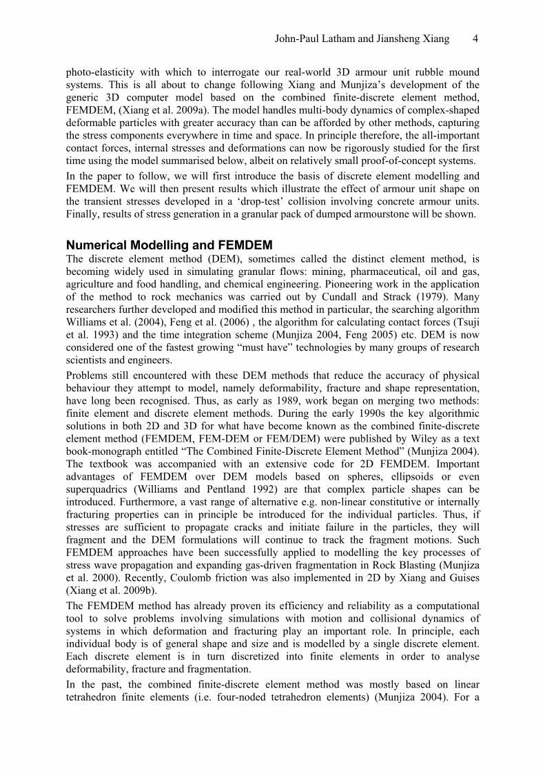
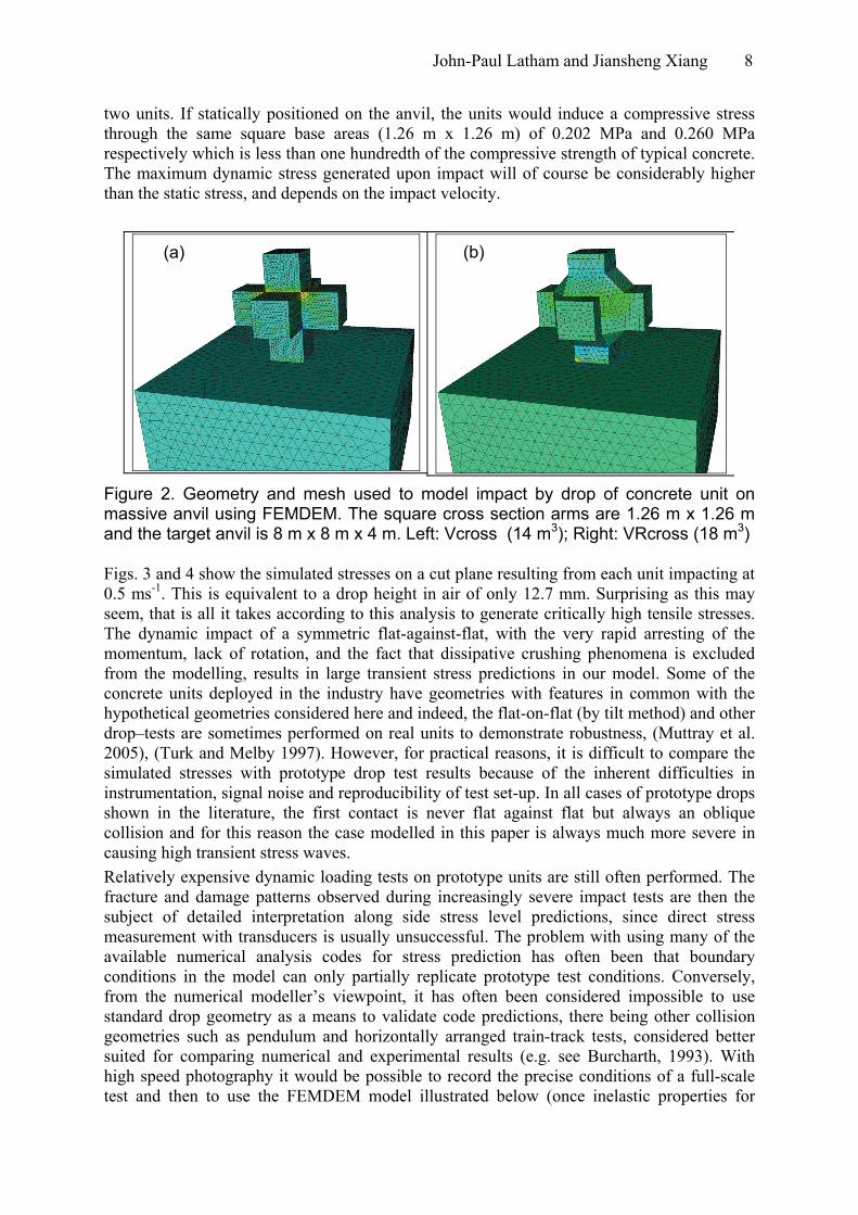
two units. If statically positioned on the anvil, the units would induce a compressive stress through the same square base areas (1.26 m x 1.26 m) of 0.202 MPa and 0.260 MPa respectively which is less than one hundredth of the compressive strength of typical concrete. The maximum dynamic stress generated upon impact will of course be considerably higher than the static stress, and depends on the impact velocity.
(b)(a)
Figure 2. Geometry and mesh used to model impact by drop of concrete unit on massive anvil using FEMDEM. The square cross section arms are 1.26 m x 1.26 m and the target anvil is 8 m x 8 m x 4 m. Left: Vcross (14 m3); Right: VRcross (18 m3) Figs. 3 and 4 show the simulated stresses on a cut plane resulting from each unit impacting at 0.5 ms-1. This is equivalent to a drop height in air of only 12.7 mm. Surprising as this may seem, that is all it takes according to this analysis to generate critically high tensile stresses. The dynamic impact of a symmetric flat-against-flat, with the very rapid arresting of the momentum, lack of rotation, and the fact that dissipative crushing phenomena is excluded from the modelling, results in large transient stress predictions in our model. Some of the concrete units deployed in the industry have geometries with features in common with the hypothetical geometries considered here and indeed, the flat-on-flat (by tilt method) and other drop–tests are sometimes performed on real units to demonstrate robustness, (Muttray et al. 2005), (Turk and Melby 1997). However, for practical reasons, it is difficult to compare the simulated stresses with prototype drop test results because of the inherent difficulties in instrumentation, signal noise and reproducibility of test set-up. In all cases of prototype drops shown in the literature, the first contact is never flat against flat but always an oblique collision and for this reason the case modelled in this paper is always much more severe in causing high transient stress waves. Relatively expensive dynamic loading tests on prototype units are still often performed. The fracture and damage patterns observed during increasingly severe impact tests are then the subject of detailed interpretation along side stress level predictions, since direct stress measurement with transducers is usually unsuccessful. The problem with using many of the available numerical analysis codes for stress prediction has often been that boundary conditions in the model can only partially replicate prototype test conditions. Conversely, from the numerical modeller’s viewpoint, it has often been considered impossible to use standard drop geometry as a means to validate code predictions, there being other collision geometries such as pendulum and horizontally arranged train-track tests, considered better suited for comparing numerical and experimental results (e.g. see Burcharth, 1993). With high speed photography it would be possible to record the precise conditions of a full-scale test and then to use the FEMDEM model illustrated below (once inelastic properties for
John-Paul Latham and Jiansheng Xiang 9
concrete have been implemented) and set up the boundary conditions of impact and the structure and properties of the anvil relatively accurately. With these provisos (elasticity and flat-on-flat collision), the FEMDEM stress analyses of Figs. 3 and 4 are briefly discussed below. They indicate what is widely known already about tensile stress generation and designs to reduce it which, from the modelling viewpoint, is reassuring.
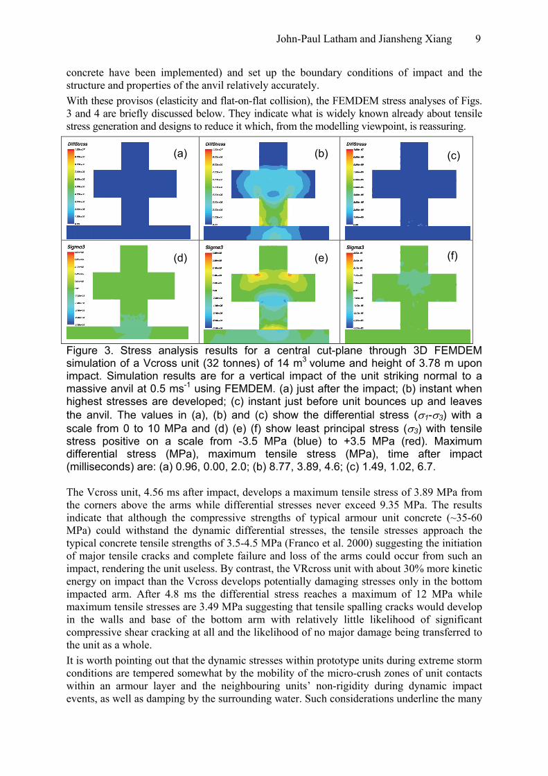
Figure 3. Stress analysis results for a central cut-plane through 3D FEMDEM simulation of a Vcross unit (32 tonnes) of 14 m3 volume and height of 3.78 m upon impact. Simulation results are for a vertical impact of the unit striking normal to a massive anvil at 0.5 ms-1 using FEMDEM. (a) just after the impact; (b) instant when highest stresses are developed; (c) instant just before unit bounces up and leaves the anvil. The values in (a), (b) and (c) show the differential stress (σ1-σ3) with a scale from 0 to 10 MPa and (d) (e) (f) show least principal stress (σ3) with tensile stress positive on a scale from -3.5 MPa (blue) to +3.5 MPa (red). Maximum differential stress (MPa), maximum tensile stress (MPa), time after impact (milliseconds) are: (a) 0.96, 0.00, 2.0; (b) 8.77, 3.89, 4.6; (c) 1.49, 1.02, 6.7.
(f) (e)(d)
(c)(b)(a)
The Vcross unit, 4.56 ms after impact, develops a maximum tensile stress of 3.89 MPa from the corners above the arms while differential stresses never exceed 9.35 MPa. The results indicate that although the compressive strengths of typical armour unit concrete (~35-60 MPa) could withstand the dynamic differential stresses, the tensile stresses approach the typical concrete tensile strengths of 3.5-4.5 MPa (Franco et al. 2000) suggesting the initiation of major tensile cracks and complete failure and loss of the arms could occur from such an impact, rendering the unit useless. By contrast, the VRcross unit with about 30% more kinetic energy on impact than the Vcross develops potentially damaging stresses only in the bottom impacted arm. After 4.8 ms the differential stress reaches a maximum of 12 MPa while maximum tensile stresses are 3.49 MPa suggesting that tensile spalling cracks would develop in the walls and base of the bottom arm with relatively little likelihood of significant compressive shear cracking at all and the likelihood of no major damage being transferred to the unit as a whole. It is worth pointing out that the dynamic stresses within prototype units during extreme storm conditions are tempered somewhat by the mobility of the micro-crush zones of unit contacts within an armour layer and the neighbouring units’ non-rigidity during dynamic impact events, as well as damping by the surrounding water. Such considerations underline the many
John-Paul Latham and Jiansheng Xiang 10
means by which collision energy will be more benignly absorbed than by the collision of a flat face against relatively immovable flat base as modelled in Figs. 3 and 4. These together constitute the degree of cushioning that Zwamborn and Phelp (1988) attempted to calibrate, as described above. Further improvements to these purely elastic stress development predictions will be possible in the future within the FEMDEM framework by introducing all the neighbouring units in the pack as separate discrete bodies and implementing energy dissipating constitutive behaviour such as an elastic-plastic relation and ultimately a fracture model, as was implemented in the 2D case. In summary, the results of this test case provide confidence that the FEMDEM method has the capability to tackle the dynamics of complex-shaped geometries and massive granular systems typical of concrete armour and rock armour layers.
Figure 4. VRcross unit of 18 m3 volume and height of 3.78 m. See Fig. 3 caption for key to stress contours. Maximum differential stress (MPa), maximum tensile stress (MPa), time after impact (milliseconds) are: (a) 0.88, 1.47, 2.4; (b) 12.0, 3.49, 4.8; (c) 2.0, 0.65, 6.8.
(a) (b) (c)
(d) (e) (f)
Table 2. Numerical model parameters for 3D FEMDEM simulation of Vcross and VRcross unit collisions (see Figs. 3, 4)
Parameter Units Value Height m 3.78 Square cross section area of arms
m2 1.59
Mass Mg 32.8, 42.1 Impact velocity ms-1 0.5 Young’s Modulus GPa 26.6 Poisons Ratio - 0.205 Density Mg/m3 2.34
Application: dumping of rock armour in a rectangular bin In this example, the potential ability to capture the entire system of units during dumping/placement is illustrated with an irregular shape obtained from a library of shapes
John-Paul Latham and Jiansheng Xiang 11
captured by laser scan from aggregate pieces, (Latham et al. 2008). The shape chosen here is not dissimilar to a possible armourstone shape and is represented at quite low resolution in order to run a simulation with ~300 blocks. To simplify the simulation of the coalescence of the particles, we have simply created a space-filling array of particles and switched gravity on. In Fig. 5, part of the motion history is captured and stress development in time and space has been contoured with a colour contour scale indicating the Von Mises stress (a component of stress often used to capture the intensity of stress that governs the magnitude of the inelastic deformation of plastically deforming solid materials). The model does not capture the friction between units. Development of an appropriate friction formulation is also work in progress. However, this multi-body example capturing all velocities and showing the ability to examine the stress components through any slice in time and space throughout a dynamic process or when the particles are at rest is an indication of the potential of these methods to examine flowing granular systems as well as pseudo-static responses to loaded systems.
(a) (b) (c)
(d) (e)
Figure 5. (a) – (d) Deposition sequence showing motion and stresses of 288 monosized angular rock-like boulders (bodies of about 40 kg) during dumping in a 5.26m × 5.3m × 3.87m bin (front face not shown). (e) two cut planes from Fig 5d.
Concluding remarks Practically any particle shape can be captured by laser scanner or alternative device and converted to surface and volumetric computational meshes for further mechanical modelling with DEM or FEMDEM. For faceted and angular concrete units and rock blocks used in armour layers, FEMDEM provides excellent shape representation and potential to model motion and fragility for static and dynamic problems. It also provides a powerful tool for examining stress chains within granular packs of armour units, e.g. showing where units in
John-Paul Latham and Jiansheng Xiang 12
the toe of a structure are carrying excessively high stresses while other units are carrying very little. Much research has contributed to FEMDEM to get to this point of proof-of-concept. The remaining challenges for modelling armour unit and armour layer behaviour are to include more realistic e.g. elastic-plastic constitutive and contact friction models together with improvements in computational efficiency. We anticipate this solids technology will be operational in 3 to 5 years time. The hope is that worldwide effort to create suitable wave tank simulators and coupled models to handle wave-structure interactions will have similarly progressed. Achieving this would herald the beginning of a shift from empirical towards more fundamental design processes for rubble mound structures which will no doubt play an important part in adapting to climate change and sea-level rise.
ACKNOWLEDGMENTS The authors are grateful for funding from EPSRC under grant GR/S42699/01 GR/S42705/01 and industrial support from Sogreah, CLI and Baird & Associates. We wish to thank ICT-HPC at Imperial College for computer resources and support.
REFERENCES Baird, W.F., Caldwell, J.M., Edge, B.L., Magoon O.T. & Treadwell D. 1984. Report on the damage to the Sines breakwater, Portugal, Proc ICCE, pp 1454-1470, ASCE, New York. Burcharth, H. F. 1981. Full-scale dynamic testing of dolosse to destruction, Coastal Engineering 4, 229-252. Burcharth, H. F. 1993. Structural integrity and hydraulic stability of dolos armour layers. Hydraulics and Coastal Engineering Laboratory, Department of Civil Engineering Aalborg University, Series Paper No 9. ISSN 0909-4296. Burcharth, H. F. d'Angremond, K. et al. 2000. Empirical formula for breakage of dolosse and tetrapods. Coastal Engineering 40, 183-206. Cundall, P.A. and Strack, O.D.L., 1979. Discrete numerical model for granular assemblies. Geotechnique. 29(1) 47-65. de Souza Neto, E.A., et al., 1996. Design of simple low order finite elements for large strain analysis of nearly incompressible solids. International Journal of Solids and Structures. 33(20-22) 3277-3296. Edge, B. L., Baird W. F., Caldwell, J. M., Fairweather, V., Magoon, O. T. & Treadwell, D., 1982. Failure of the breakwater at Port Sines, Portugal, ASCE, New York, 278 pp. Feng, Y.T., Li, C.F. and Owen, D.R.J. 2006. SMB: Collision detection based on temporal coherence. Computer Methods in Applied Mechanics and Engineering, 195(19-22) 2252-69. Feng, Y.T., 2005. On the central difference algorithm in discrete element modelling of impact. International Journal for Numerical Methods in Engineering,. 64(14) 1959-80. Franco, L, Noli, A., De Girolamo, P. and Ercolani, M 2000. Concrete strength and durability of prototype tetrapods and dolosse: results of field and laboratory tests. Coastal Engineering, 40, Issue 3, June 2000, 207-219. Gomez-Martin, M. E. and Medina, J. R. 2009. Cubipod concrete armour unit and heterogeneous packing. In: Proceedings of International Conference on Coastal Structures, Venice, July 4-7 2007. Guillén, M. 2008 Large breakwaters in deep water in northern Spain. Proceedings of the Institution of Civil Engineers, Maritime Engineering 161, December 2008 Issue MA4. p175-186 doi: 10.1680/mean.2008.161.4.177.
Hald, T and Burcharth, H. F. 2000. An alternative stability equation for rock armoured rubble mound breakwaters. Proceedings of the 27th International Conference on Coastal Engineering (ICCE 2000), Sydney, Australia. 1921-1934. Latham, J.P. Munjiza, A. Garcia, X. Xiang, J. Guises, R. 2008. Three-dimensional particle shape acquisition and use of shape library for DEM and FEM/DEM simulation. Minerals Engineering, 21 (11), p.797-805, Oct 2008. doi:10.1016/j.mineng.2008.05.015. Latham, J.-P., Mindel, J., Xiang, J., Guises, R., Garcia, X., Pain. C.,Gorman, G., Piggott, M., Munjiza, A., 2009. Coupled FEMDEM/Fluids for coastal engineers with special reference to armour stability and breakage. Geomechanics and Geoengineering Volume 4, Issue 1, 797-805. dx.doi.org/10.1080/17486020902767362. Lillevang, O.J., Raichlen, F., Cox, J.C. & Behnke, D.L., 1984. A detailed model study of damage to a large breakwater and model verification of concepts for repair and upgraded strength, Proc. 19th ICCE, Houston, publn. ASCE, New York Maddrell, R. 2006. Lessons re-learnt from the failure of marine structures. In: Int. Conf. on Coastlines, Structures and Breakwaters 2005, Institution of Civil Engineers. London. 139-152. Melby, J. A. and Turk, G. F. 1997. Core-loc concrete armour units: Technical guidelines. USACE, WES, Rep CHL-97-4. Munjiza, A., 2004. The Combined Finite-Discrete Element Method.: John Wiley & Sons. Munjiza, A., Latham, J.P., and K.R.F. Andrews, 2000 Detonation gas model for combined finite-discrete element simulation of fracture and fragmentation. International Journal for Numerical Methods in Engineering, 49(12): p. 1495-1520. Muttray, M., et al. 2005. In: Int. Conf. on Coastlines, Structures and Breakwaters 2005, Institution of Civil Engineers. London. 556-567. Myrick, G. B. and Melby, J. A. 2005. Monitoring of Dolos Armor Units at Crescent City, California, USACE,WES ERDC/CHL TR-05-10. Tsuji, Y., Kawaguchi, T. and Tanaka, T. 1993. Discrete particle simulation of two-dimensional fluidized bed. Powder Technology. 77(1): p. 79-87. Williams, J.R. and Pentland, A.P. 1992. Superquadrics and modal dynamics for discrete elements in interactive design. Engineering Computations (Swansea, Wales). 9(2): 115-127. Williams, J.R., Perkins, E. and Cook, B. 2004. A contact algorithm for partitioning N arbitrary sized objects. Engineering Computations 21(2): 235-48. Xiang, J., Munjiza, A, Latham, J.-P., 2009a. Finite strain, finite rotation quadratic tetrahedral element for the combined finite-discrete element method, International Journal for Numerical Methods in Engineering DOI: 10.1002/nme.2599. Xiang, J., Munjiza, A., Latham, J.-P. and Guises, R., 2009b. On the validation of DEM and FEM/DEM models in 2D and 3D. Engineering Computations. Available on line June 09. Zwamborn, J.A., and Phelp, D. 1988. Structural tests on dolosse, ASCE/WPCOE Sem. on Stresses on Concrete Armor Units, ASCE.