www.kimray.com LOW PRESSURE CONTROL VALVES DIRECT ACTING MODEL DA All Pictures shown are for illustration purpose only. Actual product may vary due to product enhancement. Standard Configuration Code † Order Code Line Size Connection Type Inner Valve Size Max. W.P. †† psig Cv Cf BDA1SADFS EUA2 1" NPT 1" 300 13.2 0.74 BDA1SADRS EUA3 1/2" 5.00 0.75 BDA2SADFS EUB2 2" NPT 2" 300 47.0 0.84 BDA2ARDFS EUC2 150RF 250 BDA2SADRS EUB3 NPT 1 1/4" 300 21.0 0.75 BDA2ARDRS EUC3 150RF 250 BDA3SADFS EUE2 3" NPT 3" 300 117 0.75 BDA3ARDFS EUF2 150RF 250 BDA3SADRS EUE3 NPT 1 5/8" 300 34.0 0.82 BDA3ARDRS EUF3 150RF 250 BDA4SADFS EUG2 4" NPT 4" 300 210 0.75 BDA4ARDFS EUH2 150RF 250 BDA4SADRS EUG3 NPT 2" 300 55.0 0.80 BDA4ARDRS EUH3 150RF 250 BDA4ARDFS EUI2 6" 150RF 6" 250 480 0.75 BDA4ARDRS EUI3 150RF 3" 250 120 0.80 NOTES: For standard & optional seals, metals, Cf Cv values, material specifications & dimensions see technical data on pages 02:I - 02:VI † For Corrosive service remove last "S" & replace with "C" † For KimCoat option remove last "S" & replace with "K" † For code builder see page 03:00.2 †† Max W.P. values based on -20°F to 100°F. APPLICATIONS: Liquid metering vessels where a 12 to 15 psig back pressure is desired. Any system which requires a valve to receive a 30 psig maxi- mum pilot signal on either or both sides of the main diaphragm operating at pressures up to 300 psig. FEATURES: Tight shut-off Single soft seat Removable valve seat All internal parts can be removed with valve in line Spring loaded to hold 5 to 6 psi back pressure Full line size opening: Ratio of diaphragm to seat area is 2:1 Reduced opening: Ratio of diaphragm to seat area is: 8:1 on 1" & 5:1 on 2", 3", 4", and 6" CERTIFICATIONS: Canadian Registration Number (CRN): 0C15737.24567890NTY (Ductile) 0C15620.24567890NTY (Steel) Kimray is an ISO 9001- certified manufacturer. Oil 1/4" NPT Fitting Stem Assembly Diaphragm Pressure Upstream Pressure Downstream Pressure Issued 10/20 02:20.1
Transcript
www.kimray.com
LOW PRESSURE CONTROL VALVESDIRECT ACTING
MODEL DA
All Pictures shown are for illustration purpose only. Actual product may vary due to product enhancement.
Standard Configuration Code †
Order Code
Line Size
Connection Type
Inner Valve Size
Max. W.P. †† psig Cv Cf
BDA1SADFS EUA21" NPT
1"300
13.2 0.74
BDA1SADRS EUA3 1/2" 5.00 0.75
BDA2SADFS EUB2
2"
NPT2"
30047.0 0.84
BDA2ARDFS EUC2 150RF 250
BDA2SADRS EUB3 NPT1 1/4"
30021.0 0.75
BDA2ARDRS EUC3 150RF 250
BDA3SADFS EUE2
3"
NPT3"
300117 0.75
BDA3ARDFS EUF2 150RF 250
BDA3SADRS EUE3 NPT1 5/8"
30034.0 0.82
BDA3ARDRS EUF3 150RF 250
BDA4SADFS EUG2
4"
NPT4"
300210 0.75
BDA4ARDFS EUH2 150RF 250
BDA4SADRS EUG3 NPT2"
30055.0 0.80
BDA4ARDRS EUH3 150RF 250
BDA4ARDFS EUI26"
150RF 6" 250 480 0.75
BDA4ARDRS EUI3 150RF 3" 250 120 0.80
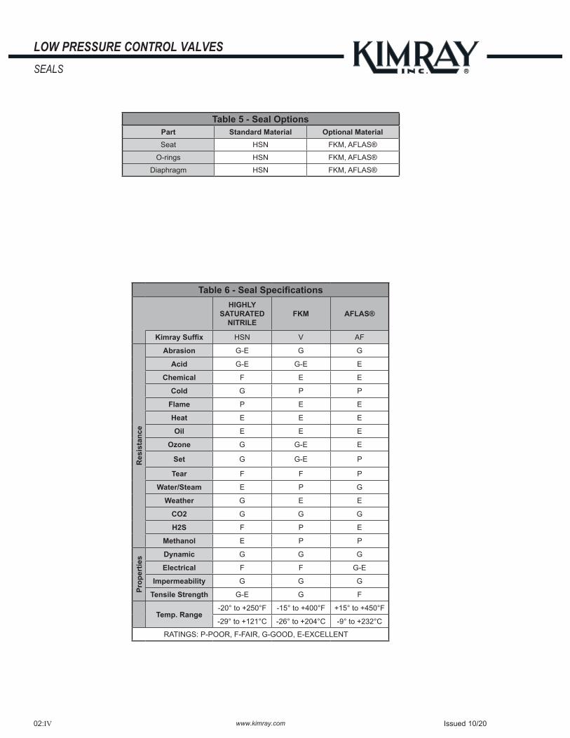
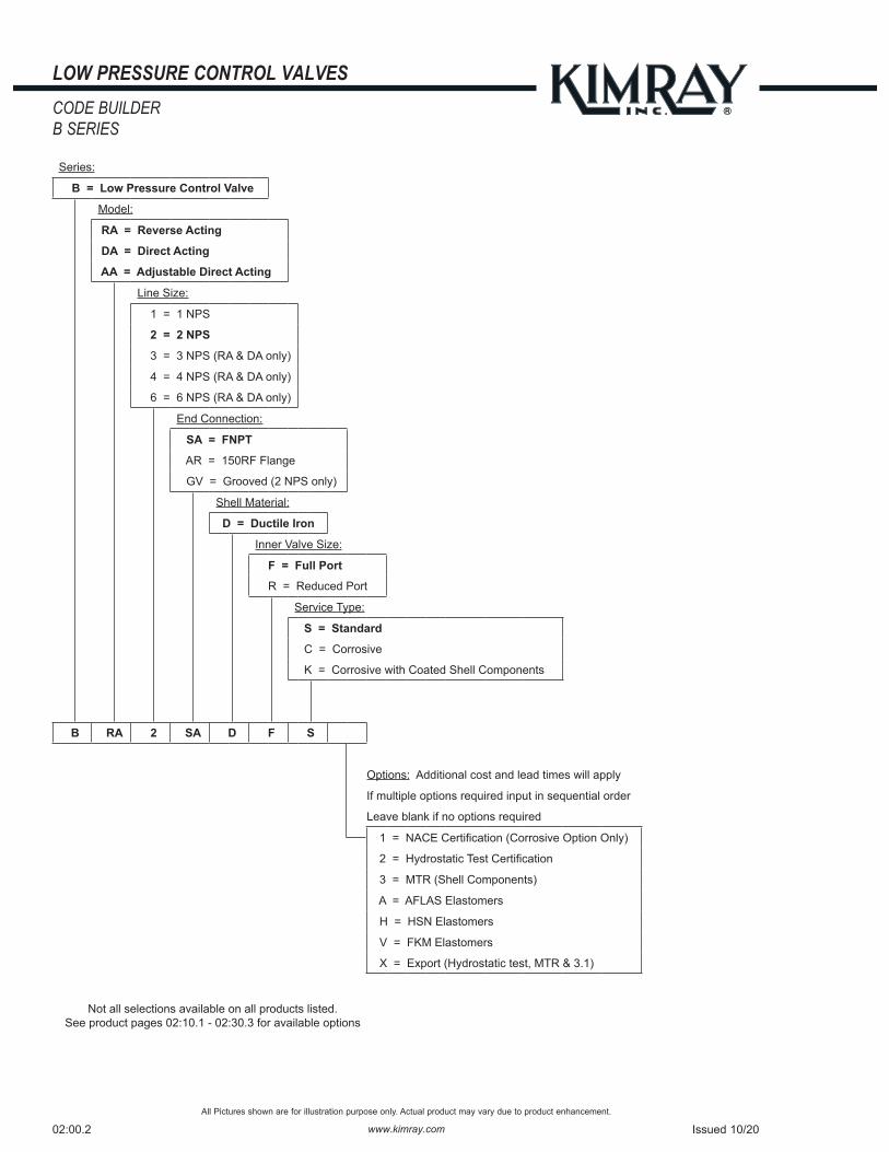
NOTES:For standard & optional seals, metals, Cf Cv values, material specifications & dimensions see technical data on pages 02:I - 02:VI† For Corrosive service remove last "S" & replace with "C"† For KimCoat option remove last "S" & replace with "K"† For code builder see page 03:00.2†† Max W.P. values based on -20°F to 100°F.
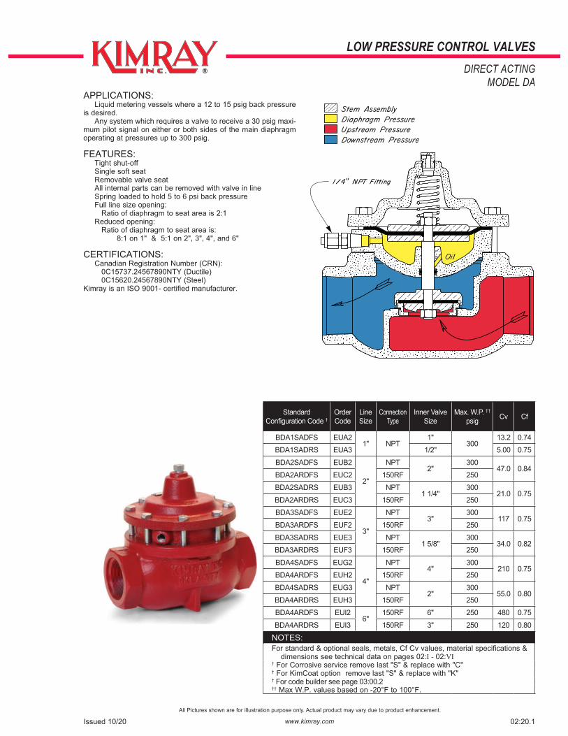
APPLICATIONS: Liquid metering vessels where a 12 to 15 psig back pressure is desired. Any system which requires a valve to receive a 30 psig maxi-mum pilot signal on either or both sides of the main diaphragm operating at pressures up to 300 psig.
FEATURES: Tight shut-off Single soft seat Removable valve seat All internal parts can be removed with valve in line Spring loaded to hold 5 to 6 psi back pressure Full line size opening: Ratio of diaphragm to seat area is 2:1 Reduced opening: Ratio of diaphragm to seat area is: 8:1 on 1" & 5:1 on 2", 3", 4", and 6"
CERTIFICATIONS: Canadian Registration Number (CRN): 0C15737.24567890NTY (Ductile) 0C15620.24567890NTY (Steel)Kimray is an ISO 9001- certified manufacturer.


![Welcome [] · Public Open House. Bridge MP 370.7 Pier Replacement Project Figure. 1 N e n a n a R i v e r N e n a n a R i v e r a a a 28 27 33 34 ARRC Bridge at Ferry (BR 370.7) Contractor](https://static.documents.pub/doc/80x56/5f9a19e805206c28a0285462/welcome-public-open-house-bridge-mp-3707-pier-replacement-project-figure.jpg)


