74
APRIL 1925 No. 4 VOL3 www.americanradiohistory.com

ELECTRICAL COMMUNICATION
F. B. Jewett
A Journal of Progress in the Telephone, Telegraph and Radio Art
EDITORIAL BOARD
E. B. Craft F. Gill G. E. Pingree H. E, Shreeve E. A. Brofos
J. L. McQuarrie P. K. Condict
J. F. Rhame, Editor
Published Quarterly by the
INTERNATIONAL WESTERN ELECTRIC COMPANY INCORPORATED
195 BROADWAY. NEW YORK, N. Y., {). S. A.
Charles G. DuBois, President George C. Pratt, Secretary J. W. Johnston, Treasurer
Subscription $1. 5 0 per year; single. copies 5 0 cents
Volume III APRIL, 1925 Number 4
CONTENTS FULL AUTOMATIC TELEPHONE SYSTEM IN KRISTIANIA-
NORWAY . . . . . . . . . . . . . . . . . . . . . . . . . . . . . . . . . . . . . . . . . . 231 By M. L. Kristiansen
TELEPHONE TRANSMISSION MAINTENANCE PRACTICES . . . . . 246
By W. H. Capen
SELECTIVE CIRCUITS AND STATIC INTERFERENCE . . . . . . . . . . 267
By J. R. Carson
METALLIC POLAR-DUPLEX TELEGRAPH SYSTEM FOR LONG SMALL-GAGE CABLES . . . . . . . . . . . . . . . . . . . . . . . . . . . . . . . 276
By J. H. Bell, R. B. Shanck and D. E. Branson
v OICE- FREQUENCY CARRIER TELEGRAPH SYSTEM FOR CABLES 288 By B. P. Hamilton, H. Nyquist, M. B. Long and
W. A . Phelps
NEW KEYBOARD PERFORATOR FOR THE BAUDOT PRINTING TELEGRAPH SYSTEM . . . . . . . . . . . . . . . . . . . . . . . .. . . . . . . . 295
By A . E. Thompson
www.americanradiohistory.com

Ak'.£R
I I I I I
,'
i I I , , ,,")
1-, AKER
--_..,.,,,
..... ---....... ... __
- ... ,
AKER
' \ ' \ ' \
\ \ \ ·\
\ \ \ l I I I t '"""'
Kristiania Telephone Network, Trunk Routes and Positions of Exchanges
----
www.americanradiohistory.com

The Full Automatic Telephone System in Kristiania-Norway By M. L. KRISTIANSEN
Chief Engineer, Kristiania Telefonanlaeg
THE first telephone exchange in Kristiania, the capital of Norway, was opened early in 1880 by the Inter
national Bell Telephone Company. Shortly afterwards, another company, provided with a municipal license, was started in competition with the Bell Exchange. This company, "Kristiania Telefonforening," opened its exchange in the summer of 1881 . The inconvenience and difficulties which resulted from having two separate companies operating in the same area were soon evident and, after three years of fighting, the municipal authorities peremptorily requested the competitors to make peace and to form a single company. The result of this fusion was the " Kristiania Telefonselskaµ, " which forms the nucleus of the present local telephone system in Kristiania. This company had, at the commencement, about 1 ,300 lines and 1 ,600 subscribers' sets. On the 1st January, 1901, the whole local telephone system was taken over by the Government and became part of the State telephone system.
As a matter of interest, it may be mentioned that all telephone exchanges in Kristiania with the exception of the small exchange built by the " Kristiania Telefonforening," were manufactured by the Bell Telephone Manufacturing Company, and that the automatic exchanges now being installed are being supplied by the same company from their factory in Antwerp.
When the present manual exchange was opened in 1896 it typified the latest construction in manual exchanges. It is a local-battery exchange, with multiple jacks and self-restoring drops, the multiple having capacity for 10,000 lines.
As the tariff was cheap-80 kroner per annum (flat rate)-and the city prosperous and progressive, this exchange had to be extended after comparatively few years; a second exchange of the same type and equal capacity was therefore
installed. At the same time, the city had grown
beyond its original boundaries al?-d five satellite
exchanges had to be installed in the suburbs.
In 1906 the situation had developed to such an extent that the manager, Mr. Iversen, sent plans and proposals to the Telegraph Administration for the reconstruction of the whole exchange system. Difficulties of different descriptions, however, arose and the question was postponed until 1912, when a committee was sent abroad to study the latest developments with special reference to the automatic exchange system which had then begun to get a foothold in America and on the Continent of Europe. This committee, of which the manager was a member, gave on its return a very comprehensive report to the Telegraph Administration and recommended the introduction of a full automatic system in Kristiania. The reason given was that calculations based on careful investigations showed that a full automatic system would give rise to the lowest annual charges per line. This recommendation was approved by the Director-General of Telegraphs and by the Minister of Public Works, whereupon the " Starting " (parliament) voted the necessary credit. At the same time, it was decided that the external plant should be laid · underground within the city area and that aerial cables and open lines should be used only where the local conditions did not justify an allunderground system.
In 1915, invitations for tenders for a full automatic system for 30,100 lines were sent out. The following exchanges were to be built :
Centrum . . ... . .. ... . ... .. . .. ... .
Frogner . .... . ... . ..... . .. . . . .
Fagerborg ..... . . .... . . . . .. .. . . . . Nord.... .. . . . . . . . . .
0st .... . .......... ......... . ... .
13,000 lines 6, 000 lines 4 ,0 00 lines 2, 000 lines 2, 00 0 lines
together with the following satellites-
Backkelaget . . . . ... . .. . .. . .. . . . . . Slemdal... . . . . .. . . . . . .. . . .
Skoien..... . .. . . . . . . . . .
Grorud ........ . . . . . . . . . . . . . ... .
1, 000 lines 1,000 lines 1 ,000 lines
100 lines
For all these exchanges, with the exception of the Skoien satellite, new buildings were to be erected. The relative positions of these exchanges and the trunk routes are shown on the skeleton map.
231
www.americanradiohistory.com

232 E L E C T R I C A L C O M M U N I CAT I O N
When the tenders were received, a committee was formed to decide upon the matter. The members of this committee were Mr. Abild. Chief Engineer of the Telegraph Administration, Mr. Iversen, Manager of the local telephone sys-
--=����:· � � '. �
of Telegraphs and Telephones, a contract was according signed in March, 1916.
The trunking scheme approved is shown in the junction diagram illustrated in Figures 1 and 2. This diagram also shows the estimated traffic
·�� �=. I --- --·-·--· __I �-------------------1-----CEN�
���llf
B�$. c -, CA,,,..1$) -..�__,,-,,,__ _ ___, Z TlilKS /iflJl/llllJlil. .l!JHl..•Hli --·-----·----·--·-·---·--·-
Si.llJU�JMN $W&O C ii>oS1r11,,�:tt
Bn1.. .• SO
� .. 11utc ...,.. ao
-;;JY ;::;; .,R? -�•ecr.s
���sk���· '-..----.-------.-----{".---..,.-!-+-'"'--"""'--+--.!-+-l-+-l-++-1-+-f------' ""''-"'8
'�-'-l#f/" �-0 o.
T«-81(,.. ""'° OI!!•� Zl"OS 11/'fl..•U
MAIN c, 7100 '""'NVAl.. LfN.E�
Figure 1-J unction Diagrarn-Kristiania Area
tern, Mr. Engset, Chief of the Traffic Branch of. the Telegraph Administration, Mr. Johannsen, Manager of the Copenhagen Telephone Company and Mr. Hultman, Chief Engineer and Manager of the Stockholm Telephone System. This committee recommended, unanimously, that the tender from the Western Electric Company for a machine switching system be accepted and, with the ·approval of the Director-General
and the number of trunks and switches to be furnished.
The work in connection with the erection of the new buildings and the reconstruction of the outside plant was immediately put in hand. Shortly after the start, however, difficulties of different kinds, consequent on the World War, began to make themselves felt. The gieater part of the equipment was accordingly scheduled
www.americanradiohistory.com

E L E C T R I C A L C O MM UN I C A T I O N 233
for manufacture at the Western Electric Company's works at Hawthorne. Shipping difficulties caused considerable delays and a large amount of equipment was lost in the S. S.
V�!!IT •ooo &.•�• l .•. Ht; .. ,#00
/Ill.II.'·
______ "7'.,..
-:0 nN.4�-�,.�
MO·l•J...11'. ll>-"70o3·•MY.t a-·roo�·A· -.r1
10 nma. ftn"M. I -----�� --L--..---·---· "'°'°' __ ..
l•NC•_.
-;;;o;.;:VE4T---·---·---· --- · --- · --- ·---· ,_""'"
116'ftC•�
MD.I'. -·------.
However, the difficulties came to an end and the first automatic exchange-Frogner-was opened to traffic on the 21st February, 1921 , with 2,000 lines. The cut-over was a good start. Only 16
trcoc l..INl!:S 4or;1uo-,.n•'
,._11,)f. l.tl'llT-' •11hXJ _.,.,,,$ 4:J"1o ·43g9s
•11110 _.,7�!19
'-T------,,F¥;r'--...,..o¥''--fll'!O'!.�-·�''"""' :C)CO/lll�Um1' ��1"1Lzi!:9 •. :1 0/¥ llOT�t# .. DW'IL••O' '---+----""N';l'"nll# w.c . .D.
·---·-
tSl:IC!Qr--�313.3 ,....e, .. 11,.,i-�
tUNiOO "�Q;JO'!>
= ""f:7! ..IU:..i'F".4...-'-<or-----,,O��="-f--+'-'=--�,,:;:,.""''
/:IPIC . .:"'"�3 ON /MIT1'0,., 01' 'JNAL. aAJ"
'N'ORD··----� -----·---. --- . - --:;:,:,,),) ,.,,., .. l. !3,., c. 1'1Zt
Figure 2-J unction Diagram-Kristiania Area
Kristianiafjord, when she was wrecked near Newfoundland. The situation was, of course, aggravated when America entered the war. At the same time, the plans for the outside work were correspondingly delayed chiefly because of the difficulties encountered in obtaining cable.
false calls were recorded and the exchange troubles were a minimum.
In March, 1922, another group of 2,000 lines was transferred from the old manual exchange to Frogner. In ] une , 1923 , the Fagerborg exchange was opened with 2 ,000 lines and during
www.americanradiohistory.com

234 E L E C T R I C A L C O M M UN I C A T I ON
Figure 4-Gear-Driven 100 Point Line-Finder Bays
www.americanradiohistory.com

E L E C T R I C A L C O M M U N I C A T I O N 235
the night between the 26th and 27th July, 1924, the Centrum Exchange, with 4,500 lines, and the Skoien satellite, with 900 lines were brought into use. The number of P.B .X's transferred to full automatic working at the same time was 105 and the total number of subscribers' sets was 9,300.
At present, the Kristiania system has about 14,000 full automatic lines and 12,000 lines con-
into force. This has, of course, complicated the situation, since the traffic studies made in the manual exchange are of less value when new exchange areas are being formed simultaneously. The decrease in the calling rate due to the introduction of the message rate is not uniform for the different automatic areas and, at the same time, the trunking between the new exchanges could not be calculated with exactitude before-
Figure 3-Friction-Driven 60 Point Line-Finder Bays
nected to the manual exchange. In December, 1924, the Slemdal satellite was cut over with about 1,000 working lines and about three or four months later another group of 5,000 lines was transferred from the old manual exchange to Centrum and Fagerborg. This represents about 20,000 full automatic lines in operation and about 7,000 lines on the old system. Two years hence, all subscribers in the Kristiania area will have full automatic telephone service.
When subscribers are transferred to the automatic system, the new message rate will come
hand. The plans had therefore to be made sufficiently flexible to meet the new conditions. This also applies to the traffic between the manual and automatic systems and vice versa. The amount of the equipment which could be installed in the old exchange was limited owing to the lack of floor space. However, serious difficulties have not arisen from this cause.
The Western Electric Company's No. 7-A Machine Switching System is so well known that a detailed description would be out of place here. Bays of friction-driven 1st line finders are shown
www.americanradiohistory.com

236 E L E C T R I C A L C O M M U N I C A T I O N
Figure 6-0ffice Buildin�
www.americanradiohistory.com

E L E C T R I C A L C O M M U N I C A T I O N 237
in Figure 3. The new type of gear-driven finders used for distributing the calls to the special service operators are illustrated in Figure 4, and bays of group selectors are shown in Figure 5. A short account with illustrations of the general plan and installation in the largest exchange-Centrum-together with a few particulars regarding the performance of the oldest
manner illustrated in the diagram shown as Figure 7 . The underground cables are taken up from the cable vault in shafts, constructed specially for this purpose in the walls, and they terminate in potheads on the wall alongside the Main Distributing Frame. From the potheads, 100 pairs silk and cotton insulated lead-covered cables run to strips of soldering tags on the
Figure 5-Selector Bays
automatic exchange-Frogner-may prove interesting.
The Centrum area is the busiest part of the city, 97% of the telephones being business lines, thus leaving 3% only for the residence lines. The exchange is located on the second floor of a new big building, Figure 6 , which is constructed for the joint use of the telegraph offices, toll exchange, Administration offices and the local telephone system. The exchange, which at the present time has a capacity for 13,000 lines, oc,cupies a floor space of 1 ,600 square meters, over which the equipment is distributed in the
"line " (horizontal) side of the main frame. The jumpering across to the protectors (exchange side of M.D .F.) is made by means of twisted flameproof rubber-covered wire. Then follows in the usual order the service meter racks, intermediate distributing frame and line and cut-off relay racks. The toll switching sections, Figure 8, are located in a separate room on the floor above and consist of four sections equipped for the time being with eight operators positions and two hospital positions. There are 40 cords on each operators' position and the traffic is handled on the order-wire basis. When a connection is
www.americanradiohistory.com

238 E L E C T R I C A L C O M M U N I C A T I O N
f')l'l",,Z.J.Nl"1d"'°3 0 c. 0 0
d'''b�
/
n
70LOJ30Dt:iAT£N 23 Figure 7
====:-:l'c:L:=._!
I : : �:: " '."'" i
m1dt::::="="" .. ='"
="=' .----------------------� L ___________ J
u'
[]::1� .. ,_, .. ,� .. ,,I I ·�,,"' ···�, I fon=i===i
'""'"' 11 �L.w�·" .. �; � .. . ;';,,.� ... �11 ........ .
D D
www.americanradiohistory.com

E L E C T R I C A L C O M M U NIC A T I O N 239
put up, the toll operator has the entire control of the connection. Fig-�re 9 shows the information desks and Figure 10 the recording and complaint positions, with the four-position Wire-Chiefs Desk in the background.
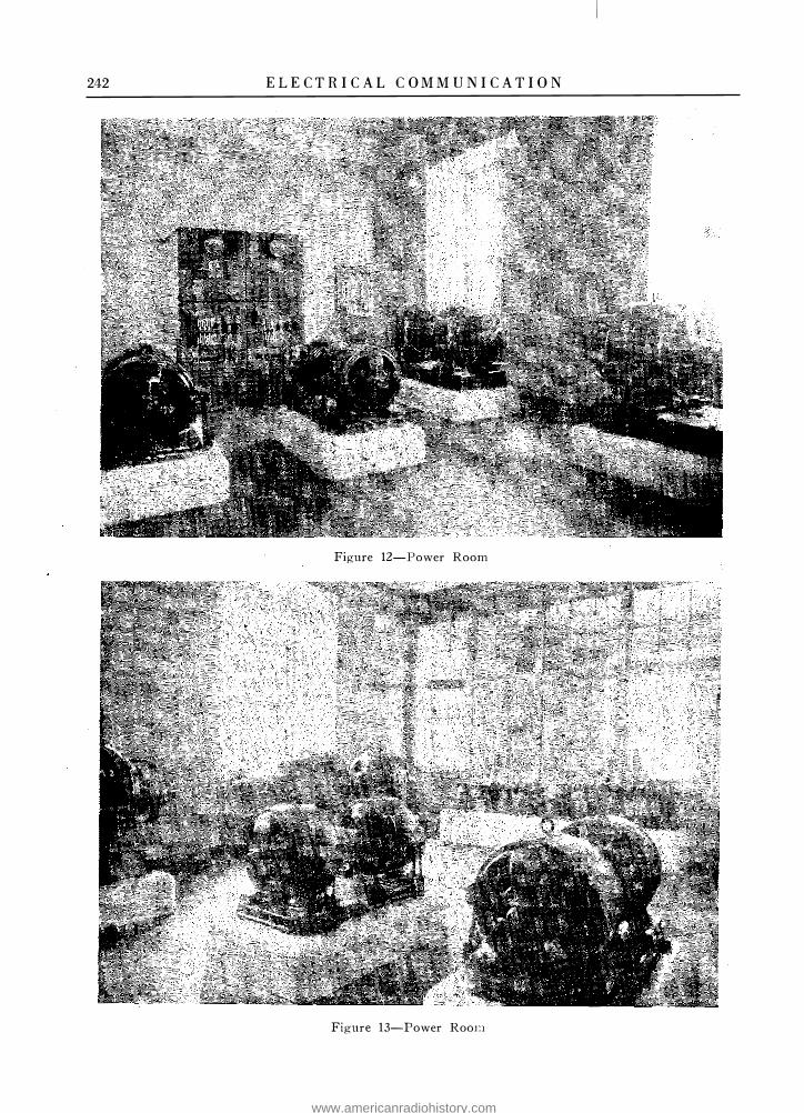
The power plant is installed in two spacious rooms next to the terminal room. One central battery, shown in Figure 1 1, of 48 volts, 4,200
driven emergency sets are provided supplying 3-phase alternating current at 230 volts. Further, there are two ringing machines ; one arranged to be run off the city supply mains and the other from the emergency sets. As a further reserve for the automatic exchange, telegraph offices, toll exchange, lits, etc . , a Die:.el oil engine with a 100 K.W. generator will be installed in the base-
Figure 8-ToU Switching and Semi-H Positions
ampere-hours capacity and seven counter E.M .F. cells are provided. Two charging sets are installed taking 230 volts, 3-phase on the motor side, the motors being of 65 horse-power. Each generator has a capacity of 36 K.W. and 600 amps. at 45-70 volts, and the two sets can be run in parallel if required. These generators have been constructed by the Oerlikon Company, of Switzerland. During the busy part of the day the generators take the exchange load direct , with the battery floating. After 4 o'clock the full load is taken by the battery. Two battery
ment. Figures 12 and 13 are two views of the power equipment and show the charging sets, the emergency sets and the ringer equipment. The powerboard shown in Figure 14 is the standard Western Electric type of black slate with instruments and fittings in copper. Automatic voltage regulation is provided. Close to the main frame are the \Vire Chief's desk and complaint desk in two separate rows. The subscriber cards and tnmble slips are sent forward and backward between the desks by means of an automatic " Haller " conveyor. A complete arrangement
www.americanradiohistory.com

240 E L ECTRICA L C O M M U N ICA T I O N
Figure 9-Information Desks
Figure 10-Wire Chief and Complaint Desks
www.americanradiohistory.com

E L ECTRICA L C O M M U N I CA T I O N 241
for automatic routine testing of cord circuits and switches is being installed.
The " special services," viz. , toll recording, . suburban outgoing calls, telegram recording, Wire Chief, information, police and fire brigade are handled on a two digit basis, i.e., the call numbers for these services are 01 , 02, 03 , 05, 08, 09 and 00. As the 0 and the 9 are nearest to the stop in the 7002 type of the
satisfaction and even when Centrum was put into operation the whole system went practically without friction at all and is giving better service every day. This is all the more significant when taken in conjunction with the fact that this exchange is by far the busiest of all the exchanges as shown by the traffic curves which also show very marked peaks from )1 to 12 and from 2 to 3 o'clock. Our only difficulty is the traffic to
Figure 1 1-Dattery Room
Western Electric Company'» dial, a subscriber can call the fire station or the police even in the dark by feeling for the finger holes nearest the stop.
For calls from the automatic to the manual exchange, the call indicator system is used and the traffic in the rever>.e direction is handled by means of semi-B positions. At present, there are 19 call indicator positions and 20 semi-B positions in operation .
From the first cut-over of the Frogner exchange, the system has worked to our entire
and from the manual exchange, but the cause is obvious when taking into account the fact that half of the sections in the old exchange are 28 years old. The public have received the automatic system very favorably and consider it a great improvement. A characteristic sign of this is that we receive, not infrequently, " Kicks " from manual subscribers because we have not yet been able to transfer them to the automatic exchange.
The particulars relating to the growth of the Frogner automatic exchange are given in Figure
www.americanradiohistory.com
242 E L E CTR I C A L C O M M U N ICATI O N
Figure 12-Power Room
Figure 13-Power Roou
www.americanradiohistory.com

E L E C T RI C A L C OM M U N ICATI O N 243
15. Curves 1 and 2 in this figure show the growth of the lines and stations from January, 1921, to January, 1 924, whilst curve 3 gives the corresponding traffic in calls per line per busy hour. The fall in the traffic curve was the result of the introduction of the measured rate which
1 .32 faults per circuit per annum, whilst the final selector with sequence switches and relays caused 0.9 faults per circuit per annum. Finally, the register circuits consisting of five numerical switches, two sequence switches and relays showed 4.3 faults per circuit per annum. The
Figure 14-Power B oard
was also accompanied by an increase in the holding time.
The extent of the troubles encountered with the machine switching equipment is very small . In the case of the 1st line finders, friction driven type, the faults per machine per annum were 0.35. For the various types of group selectors, local, incomings and thirds, an average of 0.6 faults per circuit per annum were encountered. These figures cover all parts of the circuit, relays, sequence, switch and selector. The connection circuits which comprise a 2nd line finder, register chooser, two seqence switches, relays and the 1st group switch, gave rise to a total of
performance of the equipment in general has given us much satisfaction and has certainly enhanced the reputation of the 7-A Machine Switching System.
The average time occupied in establishing connections, and the holding time for various classes of calls, are given below. These figures are up to date and represent the conditions during the first six months of 1924:
Dialling tone received in . . . . . . . . . . . . . . . . Interval before first figure is dialled . . . . . . . Time taken to dial all figures (5 digits) . . . . Selection time after last figure is dialled and
until ringing or busy signal is heard . . . . . Time taken for called subscriber to answer.
1 .2 sec. av. 1.6 " " 6 . 1
4.1 13.7
www.americanradiohistory.com

244 E L E C TR I C AL C O M MUN I C A T I O N
Conversation time including release . .. _ _ . . 122.1 sec. av. Delay between receipt of busy tone and re-
lease by calling subscriber. _ _ _ . . . . . _ _ . . . 16. 1 Time during which a connection is held on
no-answer calls . . . . . ... . _ _ _ _ . . . . . . _ . . . 54.1
As we had to build up an entirely new staff for the exchange maintenance, due to the fact
6500
6()1)(}
.5500 -·-
J
g� I �
IQ
�� � IQ �JSOO �
11-�1
1.0 I -
o. ..
av o., -- I
Q.
'f" lj7
-,,, i\
I
II II I/
I �
� 110 11-ze ,,,_
!/ � r-.... ......, J
11\ ..... ;'
I -, I I I ! i ! ' I I I I
I I ' I I
I I
to be opened later on. Exact figures for manhours for maintenance cannot therefore be given, but the result up to the present compares favorably with the experience at other exchanges.
In addition, it may be stated that there are about 250 private branch exchanges in Kris-
__...
......-----2 L---
__...
� � I
CURVE ·/·LINES.
CURVE Z·STAm rvs
'/ I 10 I - '14- I I I -., 0o
I ! - i i
-l
J \ '\ I /1 \� \ y� ri\ � � �. J
I I \ I I \ ' i I I I /r ! I I i i
I I 1 I I I I I i i I i i I : i I i a4 'h '110 *-22 v� ¥7 0o 0- 23 14- 117
C URVl!.·.!J· T'RAFFIC P£R B.H. Figure 15-Froirner Exchange-Curve of Growth
that very few mechanics could be spared from the old exchange, we have a rather large number of men in training at the Centrum, Fagerborg and_ Frogner offices for the exchanges which are
tiania. A number of these are manual C .B. Boards, but the greater part are magneto equipments which have been provisionally converted for working into the automatic system using the
www.americanradiohistory.com

EL ECTRIC A L C O M M U N ICA T I O N 245
old magneto sets furnished with dials. All of these will be replaced by manual and automatic C.B. P.B.X's. An automatic P.B.X. of the Western Electric 7.A Machine Switching type, with capacity for 180 lines, is already installed
for the offices of the Telegraph Administration. The dials and the transmitter capsules employed are furnished by the Western Electric Company, while the subsets, minus these parts, are supplied locally.
www.americanradiohistory.com

Telephone Transmission Maintenance Practices By WM. H. CAPEN
Engineering Department, International Western Electric Company, Inc.
Synopsis: The requirements for telephone systems differ greatly from those of power transmission networks and have necessitated the development of special testing methods and technique for suitably maintaining the telephone plant. The extension of the telephone system to furnish universal service has added greatly to the complexity of the maintenance and has increased the necessity for close limits of operation for the lines and equipment. Consideration is given in this paper to the principal factors which are detrimental to telephone transmission, including their causes and effects and a few of the typical testing methods which have,peen developed to locate the defects are discussed. The testing apparatus which has been designed for use with these methods of test is also described briefly and the method of operation is given. The paper also points out the necessity for an economic consideration of the application of these testing methods, including a brief discussion of the factors involved.
INTRODUCTION
IN contrast to that of the Power Companies, the commodity sold by the Telephone Companies is not power but means of com
munication. Primarily, this is for the transmission of intelligible speech, but as a secondary service many telephone companies, especially in the United States, supply telegraph facilities ; these telegraph circuits may be superposed on the telephone circuits without interference to either.1
The complexity of the tones of the human voice, the minute powers involved, and the large attenuation of the currents of the relatively high frequencies have required the development of a system and a technique of maintenance which is unique. Not only must the telephone system be capable of transmitting intelligible speech when the connection is made, but it must also provide ready means for quickly establishing such a connection and of holding it intact for the duration of the conversation. Furthermore, to fulfill its object, the telephone system should be universal so that a subscriber in one place may talk with any other subscriber in any distant part of the country or other contiguous country. In America this has already been largely realized.4
From lines of only a few miles in length, the telephone network has expanded to thousands of miles and reaches from the Atlantic Ocean Island of Cuba to Catalina Island in the Pacitic, involving some 5,500 miles of telephone line.5 From one communication channel for each pair of
246
wires the art has developed until it is now possible to furnish on this same pair of wires 12 twoway telegraph channels and 4 two-way telephone channels.1 Great progress is being made in the development of international European telephone communication. Plans have been suggested 20
and conferences of representatives from the more vitally interested countries have given much thought to the subject. I t is perhaps not too visionary to anticipate a time when these two great telephone networks of Europe and America will be inter-connected by means of a transAtlantic channel and universal telephony will be more nearly a fact.
It is often possible to produce experimental apparatus which, under the skilled manipulation of the engineer who developed it will accomplish certain results. It is quite another proposition, however, to modify this laboratory set-up in such a way that it may be manufactured in quantity, be capable of installation and maintenance by non-technically trained forces, and be available to the operating companies at a cost which will allow adequate returns with moderate service charges, which later are often regulated by the Government and frequently placed at a low figure.
The commercializing of highly intricate and delicate apparatus is itself no small feat and is as truly an engineering achievement 2 as the fundamental development necessary for the production of the first laboratory equipment.12 The time worn adage, " Necessity is the mother of invention " has been amply illustrated in the history of the telephone art. The economic exigencies have in numerous instances been the direct cause of research work leading to the development of systems which make possible large economies through the more complete use of the telephone plant. This may be accomplished by means of superposed circuits,1 as mentioned above, or by the applicq,tion of operating methods and signalling systems by which a given number of circ'uits are in actual service a greater per cent. of the time, thus obviating the necessity for establishing more circuits.
www.americanradiohistory.com

ELECTRI C AL C 0 M M U N I C AT I 0 N 247
In the early years of the telephone art, the circuits were very short, involving not more than one or possibly two connecting or switching points. Relatively low - grade facilities could be used and little maintenance was required, since even marked changes in the transmission characteristics of the circuits would not appreciably affect the intelligibility of transmitted speech.
To-day, conditions are quite different. Universal service means long circuits and many switching points in a single connection. The introduction of repeaters in itself increased greatly the importance of uniform line characteristics; but without such repeaters the long distance service would be impossible.5 Relatively small losses at any particular point may, however, cause serious defects in an extended circuit by reason of their accumulation if such points are recurrent. Variations in efficiency of equipment , such as the change in repeater amplification, will be serious unless these factors are held within close limits. For example, consider the cable circuit between New York and Chicago which will be completed in the near future.3 The net working equivalent of these through circuits will be about 1 1 TU.* The losses in the line will be 500 T U. In order, therefore, to give an llTU net equivalent, the 19 telephone repeaters in this circuit must produce a combined gain of 489 TU. A change in the net equivalent of more than ±2.5 TU is considered unsatisfactory and it will be seen, therefore, that the repeaters must be maintained to very close gain limits. Temperature changes in the course of a year are large in such a cable circuit and may change the line loss as much as 50 TU. If not compensated for by careful maintenance of the automatic regulating apparatus used in such cases, the circuit will, of course, be inoperative.
A complete maintenance program for the telephone system must include tests for signaling efficiency and the proper operation of the many
* The Transmission Unit (TU) has recently been adopted in the Bell System to replace the Mile of Standard Cable formerly used to express transmission efficiencies. The TU is a logarithmic measure of the power ratio and is numerically equal to log 10°·1• The number of TU corre-
sponding to any power ratio is given by NTU = 10 log10 ;:.
The magnitude of TU is approximately the same as the 800 cycle mile. See References 14, 15 and 16 for discussions of the TU.
relays required in the switching circuits. No attempt will be made to include this phase in the present paper as attention will be focused entirely upon the problems of transmission maintenance in the strictest sense. It will not even be possible to cover in detail all of this latter side, but it is hoped to bring out the nature of certain defects in the telephone circuits which are detrimental to transmission, and to describe briefly some of the testing gear that has been developed to facilitate the location and elimination of such troubles.
NATURE OF DEFECTS DETRIMENTAL TO TELEPHONE TRANSMISSION
The requirements for intelligible transmission of speech necessitates that the sound, as produced by the receiver at the listening end, be of proper volume, relatively free from disturbing noises and cross-talk, and that the speech be reproduced without excessive distortion. An extremely low volume of speech, even in the absence of disturbing noises, will of course render speech unintelligible. On the other hand, it is well known that excessively loud volumes of speech will produce a feeling in the ear but not intelligible sound.11 The limits, however, between these extremes are very wide, and under the most favorable conditions it is possible to understand conversation when the intensity of the received speech varies as much as some ten billion times.16
The presence of noise, however, tends to interfere with the intelligibility, and in sufficient amounts will, of course, render a telephone system unusable. Cross-talk, or as it is sometimes. called, overhearing, is due to the transference of speech currents from one circuit to another and may, if sufficient, interfere with speech by distracting the attention of the listener and preventing his concentration o
.n the speech from the
sending end of his circuit.
Even with satisfactory conditions of intensity in reproduced speech, and freedom from disturb�
ing noises and cross-talk, it is necessary that the speech be reproduced with considerable fidelity. Tests have shown, however, that commercial telephone transmission does not require entire freedom from distortion 9•
The ability of a telephone· circuit to resist the entrance of extraneous currents, either in the
www.americanradiohistory.com

248 E L E C TRI C A L C O M M U N I C A TIO N
form of inductive interference or cross-talk, is of equal importance to the transmission characteristics of the system. Present day high-grade telephone circuits have reached a high degree of perfection in this respect. Without proper precautions, extraneous noises may be introduced into a telephone circuit from inductive interference from power lines in the neighborhood of the telephone lines. Such interference is manifest in the production of line noises of various types, ranging from clicks to steady tones. By suitable design of the circuits and particularly by proper inductive coordination of the telephone and power lines, such troubles are minimized.17
Cross-talk between two circuits, moreover, may be due to improper design, installation, or maintenance of circuits, and is caused fundamentally by unbalances between the two circuits in question or by some impedance common to both the disturbing and disturbed circuits.
The exact amount to which noise and cross-talk may be detrimental to intelligible speech depends upon the relative intensity of the disturbing currents to the telephone currents. In long telephone circuits utilizing repeaters, it may be quite possible to produce adequate volume of voice energy at the receiving end, but unless care is taken in the location of the repeaters and the amount of gain introduced by each, the amount of noise or cross-talk present in the received speech may be excessive. This condition would be caused by allowing the speech currents to attenuate to such a point that the noise currents form a large proportion of the total line energy. The introduction of amplification at the repeater points will , therefore, raise both the voice and noise levels by an equal amount, while little will be gained in the way of improving the transmission by the introduction of repeaters. It is, therefore, important in long haul circuits, that the voice level be kept above a certain amount at all points in the system.3
The decrease in the intensity of the voice currents as they progress from the transmitting to the receiving end of a telephone circuit, is due to the attenuation introduced by the line and to losses caused by associated apparatus. The attenuation caused by the line itself, as is well known, is due to the electrical relation of the constants of the line, and for a line of uniform characteristics is a steady logarithmic decrease
per unit length of line. Apparatus losses are caused largely by inefficient transformers, the shunting effects of bridged equipments, the introduction of se1ies impedances, or combinational effects of these. All of these sources of transmission loss cause a weakening of the transmitted current which must either be compensated for by amplification at suitable points or by so designing and maintaining the system that the minimum received energy is not below a value which experience has determined_ as necessary for satisfactory service.
A:o mentioned above, the telephone current must be reproduced with reasonable freedom from di:otortion. In this connection, it should be remembered that speech energy extends from a frequency of 60 cycles to above 6,000 cycles, with a maximum at about 200 cycles.9 In order to produce perfectly the original speech, it is therefore necessary, among other things, that the system transmit this range of frequencies with equal efficiency over the full range. In the absence of other distortion and with suitable volume of reproduction, such a system would not only give 1003 intelligibility for speech but would reproduce the voice with complete naturalness. Tests made in the Bell System Laboratories have shown that nearly 1003 intelligibility may be obtained by the uniform transmission of a considerably narrower band of frequencies than this.9 The transmission of frequencies from approximately 200 cycles to about 2 ,500 cycles gives speech of very good intelligibility.5 Systems have been developed 10 in which this range of frequency is greatly increased , and such systems are used in connection with the transmission and reception of speech in public address systems and more universally in connection with radio broadcasting. The apparatus necessary for this higher grade of transmission is relatively elaborate and expensive and not economical for ordinary forms of telephone service.
In addition to the unequal transm1ss10n efficiency of currents of various frequencies, generally known as frequency distortion, other types of distortion may be present in telephone circuits which are not suitably laid out or maintained. In the use of telephone repeaters, distortion may be produced if the apparatus is forced to handle energy greater than the specific
www.americanradiohistory.com

E L ECTR I C A L C O M M UN I C A T I O N 249
amount determined by the characteristics of the equipment." This is generally known as overloading of the amplifier and is due to the nonlinear characteristics of the amplifiers for excessive powers, resulting in the introduction of frequencies not in the original impressed power. As is well known,18 the operation of two-way telephone circuits with repeaters requires a high degree of similarity over the range of transmitted frequencies, between the impedance characteristics of the line and those of a balancing network connected to the 3 winding transformers associated with each 22 type repeater or with the ends of a 1-wire circuit. Unbalance between the line and its network causes return currents to flow through the circuit, and if sufficient, and the repeater gains high enough, su�tained circulating currents will be obtained, resulting in a continuous tone in the associated receivers, generally spoken of as "singing." Even if the unbalances and repeater gains are not sufficient to produce actual singing, they may be sufficient to cause distortion evidenced by a peculiar ringing effect when talking on such circuits. Proper maintenance necessitates, of course, that this near approach to the singing condition be prevented.
Another form of distortion which may be noticeable on long circuits is that known as "echo." 3 This distortion is due to return currents on circuits where the total time of trans� mission is sufficiently large to cause the effect of an echo. Each point in the circuit where an electrical irregularity is present is the source of a return current, the magnitude of which will depend on the magnitude of the irregularity a:nd the equivalent of the line. Although the time of delay of such return currents may not be sufficient to cause a distinct echo either in the talker's receiver or at the listening end, it may be sufficient to cause an effect similar to reverberation in a large empty hall and may therefore seriously impair the transmission. On long circuits, this effect may be serious even though the irregularity is not sufficient to cause distortion due to the near approach to the singing point.
Still another form of distortion present in long circuits is caused by transient currents. \Vhen electrieal impulses are applied to such circuits, peculiar transient phenomena occur.
These effects have been discussed in considerable detail in previous papers a, 5 and will not be dealt with here. Suffice it to ::-;ay that transients are caused by the unequal ::;peed of transmission of different frequencies and result in a distortion of the received currents. The lower frequencies in the impressed wave reach the receiving end first, an appreciable Lime elapsing before the higher frequency components arrive and the receiving current reaches its full amplitude. Many of the speech sounds have the characteristics of an impulse and not those of a sustained tone. In extreme cases, therefore, the distortion caused by transients may be severe. The effect, of course, is dependent upon the type of circuit, but with proper methods of construction the transient effect can be largely overcome.
It is probably evident from the above discussion that the question of suitable maintenance of the telephone system from the transmission standpoint is a highly involved practice requiring great refinement of testing methods and technique. In what follows, it will be possible to consider only a few of the types of testing equipment developed for maintenance purposes.
MAINTENANCE TESTING M ETHODS
In order to suitably maintain the telephone system, it is not sufficient to have available suitable testing equipment by means of which defects may be located, but it is also necessary that some routine of tests be adopted. This is advisable in order that such tests be made at reasonably frequent and regular intervals, thereby eliminating the possibility of defects continuing for considerable periods as might be the case if testing work were carried on spasmodically. Certain types of defects are of more frequent occurrence than others and, therefore, tests for their discovery should be made more frequently than others.6 The carrying out of any of these tests, of course, requires the expenditure of money by the telephone companies for testing gear and labor. The testing program, therefore, resolves itself ·into an economic study in which the cost of tests mu:St be balanced against the decreased quality of service, if no tests are made. This is
www.americanradiohistory.com

250
Earth
Condensers
Receiver or
shunt
E L E CT R I C A L C OMMUNIC A T I O N
0·001 pF to O·Ol ..
0·01µF toO·i" O·OOOIµF toO·OOl"
Figure 4-N oise Analyzer
Te::ii 1500w 1500w
RetaYdation coll
In O·l JLF e>----4'.'l
Resista.nce shunt
Figure 5-N oise Analyzer-Circuit
no volts
zoo
1000
0
10 0
www.americanradiohistory.com

E L E C T R I C AL C O M M U N I C A T I O N 251
a rather difficult problem for exact solution, so that the maintenance program must be based largely upon experience and must include not only a determination of what tests should be made and how frequently but within what limits the equipment must be held . These considerations all depend upon the types of circuit involved and their relative importance in the system as a whole. In the Bell System, routine instructions are issued to the operating companies covering these matters, and taking into account local conditions and service requirements. 6
The complete maintenance work includes DC measurements as well as AC. The former type, which include measurements for DC resistance and insulation, are relatively wellknown and will be omitted from consideration here.6 Attention will be confined to a few of the AC tests which are in use in the Bell System.
INTERFERENCE As previously mentioned, the ability of a
telephone circuit to resist the entrance of foreign currents is of equal importance with its ability to transmit the necessary telephone currents. The presence of such extraneous currents is evidenced by noise in any receiver associated with such a circuit. It becomes necessary, therefore, to determine quantitatively the amount of such noise and whether or not it is sufficient to be detrimental.
r-'.}-z5w---1900;----ecew;tI.-___ ____ � 1 3 � i "" R � • LuH' under test I �.::'iw 19001.11 __, � ·
L-------------------...J I>---------< lfoise Shunt r- --------[b----------------1
I 600w I
: � : I N -.;;;o I : 600iP : L_ _______ ___ _. ________ _____ J V1hrntin15 element
1'1easurement of lmc 1101:'c
� Receive� � l � l'lr��nrrment of earth no1f1· -
Figure 1-N oise Measuring Set-Circuit
In order to accomplish this, a testing set known as a noise measuring set has been developed. (The schematic circuit is shown in Figure 1 . ) This instrument is portable and
includes a standardized vibrating element or arbitrary noise standard, which produces a current of comparatively low fundamental frequency rich in harmonics. Figure 2 shows the
Figure 2-N oise Measuring Set
set. A calibrated potentiometer or noise shunt is required with this set and is shown in Figure 3. The amount of noise in a circuit is found by listening in a receiver which is alternately
Figure 3-N oise Shunt
associated with the line under test and the testing circuit. The noise shunt is adjusted until it is judged that the noise from the stand-
www.americanradiohistory.com

252 ELECTRICAL COMMUNICATION
ard would cause the same interference with conversation as the line noise. There is, of course, no conversation during the test. The shunt calibration is such that the setting shows the fraction of the output current from the noise standard ·which passes through the receiver, expressed in millionths.8
In addition to determining the quantity of line noise, it is also advantageous in locating the probable source of such disturbance, to analyse the noise for its frequency content. The noise analyzer, Figure 4, the circuit of which is shown in Figure 5, provides a means for determining not only the frequencies present, hut, by the use of the noise shunt. described in the preceding paragraph, of determining roughly the magnitude of the components by comparison with the noise standard tone. The set consists further of a resonance circuit made up of a fixed inductance and adjustable capacities so arranged that the circuit may be made re»onant for any frequency between 100 and 2,400 cycles per second. This combination is incorporated in the test circuit with a shunt for regulating the volume of the noise to he analyzed and with switches so arranged that the test may be. conducted between two sides of a metallic circuit or between both sides and ground. The frequency range may be
.. .!' p " "' LINE "' '" " \ :i:
ceptible to induced currents of some frequencies than of others. This is due not only to the transmission characteristics of the line and associated equipment, hut also to the response characteristics of the receivers and the sensitiveness of the human ear. In other words, induced currents of certain frequencies cause
Figure 6-Yoltage Wave Telephone I nterference Factor Set
relatively little disturbance, say, 60 cycles, while the higher harmonics of this frequency
ls ������-6-������+-----6-���.:....:....:::...:....:..������-<I-' L&
Figure 7-Voltage Wave Telephone I nterference Factor Set-Circuit
increased by the addition of auxiliary condensers. I
One of the greatest sources of line noise is inductive interference from neighboring power lines. The telephone system is more sus-
will produce trouble. The relative amount of disturbance which a given power line may cause can, therefore, he determined by measuring the disturbing effect of its voltage or current wave in a circuit which simulates in
www.americanradiohistory.com

ELE C TRI C AL C O M M U N I C A T I O N 253
overall response a telephone system. Two testing sets have been developed, one for measuring the interfering effect of a voltage wave and the other that of a current wave. Figure 6 shows the voltage wave telephone interference factor meter and Figures 7 and 7-A the schematic diagram and calibration curve. The set is portable and is for use on power lines in which the low voltage side of the potential transformer does not exceed 700 volts. It is composed of a thermocouple associated with a galvanometer which is connected to the power
@��.R��RATIOl Bv • • . • • • • • • . •
�flrlAt. Mtl! Tlf'Ll[R' Accwrt ro W.11<1�.--12.000 1---1--
i T11CRM(I Coof\.E St1UAL l'iliM11£fl • • • • • • •
I I � I---..___ Cow Ru151 llNG( or cc..�u;. - - - . _()t;l"\lf-+--+--+---1.\---
\l--+----4
..., Cou1 ��TANcr or Hr�TCR _ _ _ _ _ _ l)lt'I'.> W IOOOO l---1--- f-+--lt----+---++-+--,f--� OPEN C1RCulT PoTCNTIM. ll • • • • • • VOLT \ � 1--1-- W1t11 CuKRnt1' ll'I Hl::ATCR AT ••••• AMf'{H{ ,.__-..-,H-i -+---+---++___,f--tl M...,,,.......-; �H Ht.nu. Ci.M£n't..AMP[llt / ' � .... f-+--+-��-���--+---1--+-l--+--+--+---I� � I \ � \ ! 6000f--+--+---+---lf--+--+--+----+�f--+-+--+----+--->.�
I � v
I\ 0 .... r--1--+--+--+--+--+----1r----7t-/ --+---+--+--+----t--+---1 � I/
v zooo f--+--+---+---l�+->4---+----+---1-+-+--+----+---l'---l/ v
""
Figure 7A-Voltage \Nave Telephone I nterference Factor Set-Calibration Curve
line through a network having the characteristic proportioned according to the disturbing effect of the frequencies, so that when a number of harmonics are present in the voltage wave, the meter indicates the square root of the sum of the squares of the individual harmonics.8 This, therefore, gives a direct indication of the interference possibilities of a voltage wave. The actual interference will, of course, further depend upon the inductive relation of the telephone and power lines.
In connection with inductive interference, much may be accomplished in minimizing the trouble by proper inductive coordination of the telephone and power systems through coopera-
tion of the two interests.17 In the United States such cooperation has accomplished a great deal and problems involving common rights of way, alternate routes and fundamental research on the subject are being given constant attention by representatives from both fields.
Another type of interference present in the telephone system and which has already been mentioned is cross-talk. Measurements of this may be made by voice tests, complex tones or by single frequency measurements. The amount of cross-talk between two circuits will vary greatly with frequency.8 Measurements at a single frequency may, therefore, give very misleading results and unless a complete frequency run is made, field measurements are ordinarily done with a complex tone, which has been found to give results comparable with voice tests. One type of cross-talk measuring set is shown in Figure 8 and the details of the panel and one type of connection are shown in Figure 9. The set is designed for use with three line impedanc_es representative of the three classes found in the plant. The set contains a slide wire resistance calibrated in cross-talk units. One cross-talk unit is one millionth of the square root of the power put into the disturbing circuit. A measurement is made by obtaining a balance between the sound in the receiver when connected to the line and when connected to the meter.
. In making measurements upon noisy lines, difficulty is experienced in obtaining a good balance. This difficulty is eliminated by connecting the set as shown in Figure 9. Two balanced receiving circuits are used to connect the receivers, the terminals of the crosstalk meter and the disturbed line in such a manner that the line noise will be heard at all times in the receivers, while the presence of the disturbed line will not affect the current flowing into the receivers from the cross-talk meter, and vice versa.
Cross-talk measurements must be made with great care and it is, of course, important that the measuring apparatus itself be free from sources of cross-talk. A set similar to that described, while satisfactory for line measurements such as are ordinarily required in maintenance work, is not suitable for cross-talk
www.americanradiohistory.com

254
a: 0 1-<C ....I ....I <.) If) 0
E L E C T R I C A L C O M M U N I C A T I O N
Top view of
Circuit for
cross-talk. mea.eurin� set
2> 0 -1 0
e.nd cross.:talk measuring; near A.C.in-put
..-----____,,Mete.r u�i,____ne. ____.�� � Tl di:;��bin�
lme. ]rid1;e network for E introducint; line. noise � �--------�� when listeninf; on cross-talk merer
� � �
3 f dts;::�bed L-------+-
._-_
-_
-_
-_
-' ____
______ -o3 � line •
Figure 9-Crosstalk Measuring Set-Details of Panel and One Type of Connection
L I N E
I
F. I
1 gu re <JA-Impedance Unbalance B ridge-Connected for Determining Phantom-to-Side Unbalance
www.americanradiohistory.com

E L E C T R I C AL C O M M U N I C A T I O N 255
measurements on certain types of apparatus in which extreme precautions must be taken to insure results of any significance, -the measurement of cross-talk in loading coil phantom groups, for example.
When the measurement * of cross-talk indi-
bridge 19 to obtain an approximate location of the unbalances. The method is adapted from a similar one for locating irregularities in the impedances of metallic telephone circuits which interfere with repeater operation. I t may be usefully applied only to circuits of considerable
Figure 8-Crosstalk Measuring Set
cates that the unbalances of the circuit are greater than the allowable limit, measurements may be made with an impedance unbalance
* This brief discussion has been taken from the recent paper by Messrs. Ferris and McCurdy-" Telephone Circuit Unbalances-Determination of Magnitude and Location "--presented at the Pacific Coast Convention of the A. I. E. E., Pasadena, California, Oct. 13-17, 1924.
length, approximating 50 miles or more of open wire. Shorter lengths may be tested in cables. The bridge is shown in schematic form in Figure 9-A connected, with a phantom circuit as a superposed reference, to locate the unbalances of a side circuit.
The bridge is made up of a pa_ir of equal ratio
www.americanradiohistory.com

256 E L E C T R I C A L C O M M U N I C A T I O N
arms with a fixed inductance and resistance which are connected in series with one side of the line and an adjustable resistance and inductance which are connected in series with the other. It is thus possible to adjust the bridge for balance whether one side of the line or the other is higher in impedance without having to reverse the hridge terminals with respect to those of the line. A telephone receiver is used as a detector and an adjustahlefrequency vacuum tube oscillator as a source of energy.
The method consists in halancing the hridge at a numher of frequencies at definite intervals in the range from 200 to 2,000 cycles and determining the magnitude and sign of the resistance and inductance unbalances which must be inserted in the hridge in order to compensate for those in the line. The values of equivalent resistance and inductance unbalance thus obtained are plotted as funtions of the frequency. From these curves a location may he determined for the unhalance or unbalances if their numher is not too great.
EFFICIENCY MEASUREMEKTS
\Vhen considering the efficiency of a telephone system or a part thereof, the most ohvious way of ohtaining a result is to talk over the system,
the communication art and will not be considered in detail. Such tests give a direct measure of the volume efficiency of the circuit to voice currents. In order to determine the intelligibility of transmitted speech, information is required on the distortion occurring in the circuit as well as knowledge of the volume of reproduction and the amount of the disturbing noise. The intelligibility may also
. be
measured directly hy recording the percentage of intelligible speech the system is capahle of producing. 9 These tests 7 are rather laborious and, consequently, not well adapted in general for maintenance work. A great number of observations must be made in order to obtain an answer of reasonahle precision when making talking-listening tests. The difficulty is due to the variables in the voice, the changes in microphone efficiency and the vagaries of the human ear. Listening tests with a single frequency tone or a steady complex tone are much more readily made. 7 Still further gains in the ease of making efficiency tests may be obtained hy using visual reading testing sets in certain cases.
Transmission efficiency tests in maintenance work are generally made with single frequencies or standardized complex tones. Considerable study has heen required to correlate these tests with direct voice tests, hut the advantages
Tran�m1•,•,•M M�.i:;ur1<v; Set � - - - - - - - - - - - - - - - - - - - - - - - - - - - - - - - - - - - - - - - - - - - - - - -- - ----- - - - --- ,
t'Y·'<•W ' I f - - - - --; ��- Si>">d•"'J L•rCv•1 ·---- - - - - -- - R«.el� Cln:uit
���·L?:::·�-(��'::;-� � : : c;,� : t; , r---i l (l
' I ' I ' I ' : : I I
,,_ _ _ _ _ J :: .• �-----
: : L' ...,1<"01 -l +--31�-· _,_r;,i_, ,_, }, .�'-��--,-J--,""'-.-.-ri�.----1... - - -J "- - - - - - - - ·· ·· - - - - - ' Sr,Vl·..,� l-::'. :ft � �;:
Figure J O-Transmission Measuring Set
Simplified Diagram Showing Arrangement for Straightaway Tests. Solid Position of Switches Show Connections for Calibrating. Dotted Position of Switches Show Connections for Measuring
listening at the other end and comparing its volume of reproduction with that of some standard system.15 If parts of a system are to be considered, a test can similarly be made by comparing one part with a standard part or by noting the change in volume by inserting and removing the part in question.7 This type of test is familiar to all acquainted with
have justified the research. In certain cases, efficiency measurements covering a wide range of single frequencies are made. Numerous testing sets have been developed to meet the various types of main tenance work, but only two typical sets will be considered ; one is for measuring transmission loss and the other is designed to measure repeater gains.
www.americanradiohistory.com

E L E C T R I C A L C O M M U N I C A T I O N 257
MEASURING TRANSMISSION LOSSES
Figure 10 gives a schematic diagram of the circuit used for and Figure 11 shows the set. Similar to a large number of testing sets designed for maintenance work, this set is portable. I t employs a direct reading meter for visual indication. It is calibrated in miles of standard cable * from 0 to 30, making possible the measurement of losses between these limits to an
While any source of alternating current having the proper output, suitable wave form and frequency can be used, a special oscillator generating a 1 ,000-cycle current has been designed for use with this set. This oscillator will be described later.
Both the measuring set and its oscillator operate satisfactorily from the regular 24-volt central aoffice battery s a source of power. The set
Figure 1 1-Transmission Measuring Set
accuracy of 0.1 mile of standard cable. These measurements may be made with great rapidity. The set is also arranged to permit the current supply conditions of subscribers' operators' cord circuits and switching trunks to be measured.
* The testing equipment now calibrated in miles of standard cable is being converted to read in transmission units (TU) as rapidly as possible. See references 14, 15 and 16 , for discussions of the T U.
contains two vacuum tubes,. but does not require a separate plate battery, the 24-volt battery supplying both filament and plate currents. The detailed operation of this set has been described in previous publications and will not be gone into in detail.7, s Briefly, the operation of the set com,ists of an application of the substitution method in which the total loss caused by a calibrated network is decreased so that the loss caused by the remaining portion
www.americanradiohistory.com

258 E L E C T R I C A L C O M M U N I C A T I O N
of this calibrated network, plus the unknown network, is the same as the original total loss. This is evidenced by obtaining an equal meter deflection under the two conditions of test.
With this set tests may be made on loops where both terminals are available ; and by triangulation methods losses of straight circuits may be obtained by looping with other circuits at the distant end, provided the efficiency of one of the circuits used in the triangulation is known. The losses of cord circuits, repeating
·energy of the set at the rece1vmg end in a similar manner to that outlined above.
In order that the gain given by any repeater of either the two-wire or four-wire type may be checked and the apparatus calibrated for the actual gain at any setting of the gain control, it is necessary to provide at least one repeater gain set in a repeater station. One type of such a set is shown in Figure 13 and the schematic diagram of the circuit is given in Figure 12. This set is capahle of measuring gains up to
r- --------- - ----- ------- ------- -------- ----- ---- - -1 1 5-mile steps Re�eate.r !Input Repeatint; .__-'V'vvv..IVV'""---"��------, lcontrol coil In Out ('I') I ,..... I I I I I I
3 2 .....
I Gain unit ......
_ J � - - - - -- - - - - - - ------ - - - - - - ------------- - ----
r - - - -- -- - - ------ -------- - - - - ---- - -- - - - -, 1 Amplifier circuit lrrput l I transtormer I 2 111---0---. I Q.) i:: I S I I � I ,........ I � I c!l L---��-+---' I I I I I I 1 Rheostat Galvanometer - 1 1 "' · t 1.. ro---Jddjuster I 1 I 1:-11111 >JWl CH
. -=;o- :
L _ _ _ -2'.:_ _ _ _ _ _ h��tl��--------- -------------� Fi!?"ure 12-Repeater Gain-Measuring Set-Circuit
coils, etc. , may also he determined . If two of these sets are available, one at either terminal of the line, the efficiency of the line may be determined directly by a straight-a-way test. The connections are shown in Figure 1 0. This test is accomplished by adjusting the AC input to the unknown line and the input of the sending circuit of the set at the receiving end to the same value and then comparing the output energy from the line under test with the output
46 miles of standard cable in steps of Yz mile. This particular set is designed to mount on the same racks as the repeater and consists of two panels, one of which comprises the gain unit and the other an amplifier unit. In the operation of the set, an alternating current of any frequency from 100 to 3,000 or more cycles per second is applied to the input terminals of the gain unit and to a regulating device from which it passes to a repeating coil. The cur-
www.americanradiohistory.com

E L E C T R I C A L C O M M U N I C A T I O N 259
rent then flows through two separate circuits which are connected in series on the secondary side of the coil. These two separate circuits again join in the switching key.
Referring to the diagram, the current in the upper circuit of the gain unit passes through an
The amplifier circuit which is shown in the lower part of Figure 12, contains two vacuum tubes, the first acting as an amplifier and the second as a detector. A galvanometer is connected in the plate circuit of the latter. The key of the gain unit is connected to the first
Figure 1 3-Repeater Gain-Measuring Set
artificial line, which is shunted by a variable resistance controlled by a dial switch and is designed to give losses in steps of 5 standard miles. The terminals of this artificial line are connected to the input of the repeater under test, the output terminals of which are connected to another artificial line closed with the resistance. The terminals of this latter resistance are connected to a switch as shown.
The lower circuit of the gain unit contains a fixed resistance shunted by another variable ·
resistance, the latter being controlled by a dial switch designed to give losses in steps of 72 mile of standard cable. Terminals of this adjustable resistance are also connected to the key.
tube of Lhe amplifier through an input transformer. With no alternating current applied, the reading of the galvanometer is adjusted to 10 divisions by varying the grid potential on the detector tube by means of an adjustable resistance connected across the filament of the first tube. It will be seen th<!-_t the key in the gain unit will connect the amplifier to either of the two circuits in this unit. In order to make a test for the gain of a repeater, the connections are made as described, the alternating current is applied and the two adjustable dials are operated until the same galvanometer deflel tion of approximately 50 divisions is obtained for either position of the key. It may be seen
www.americanradiohistory.com

260 E L E C T R I C AL C O M M U N I C A T I O N
that under the above-named condition, the voltages developed at the end of both the upper and lower circuits of the gain unit are equal, and since the currents which enter these two circuits are identical, the gain given by the repeater must, of necessity, be equal to the difference of the losses caused by the shunts and the
at single frequencies between 100 and 3 ,000 or more cycles may be used.
BALANCE M EASUREMENTS
As previously mentioned, the proper operation of two-way circuits equipped with repeaters
Fi gure 1 4-Tmpedance Irregularity M easuring Set
artificial lines included in the two circuits.8 A panel mounted sing-le frequency oscillator
consisting of two vacuum tubes is generally provided at repeater stations for use with this set, although any oscillator capable of giving power
requires a high degree of similarity between the impedance characteristics of the line and the balancing network associated with each 3 winding transformer. In a line of perfectly uniform constants, the impedance characteristic will vary
www.americanradiohistory.com

E L E C T R I C A L C O M M U N I C A T I O N 261
gradually within the range of frequencies transmitted by the line. Any sudden change from a line of one type to that of another, the insertion of equipment, irregular spacing of loading coils, the use of wrong types of inequality ratio repeating coils, etc., will cause reflection of the current wave at the point of irregularity.7 This reflected wave will return to the sending end of the line and cause an irregularity in the impedance at some frequency which is dependent upon the line characteristic and the distance
B ? I t..:.-.:J' *lZOOw P
A
Line
conditions of opening and shorting the other line. The total calibrated gain introduced bv both elements of the repeater is then equal t� the singing point. Two values of singing point will be obtained in general, corresponding to the open circuited and short circuited condition of the second line. The lower value is taken as the one of interest. These two values of singing point correspond to two possible phase polings of the current. Either poling may occur in practice and it is, therefore, advisable to
G z-stage vacuum-tube a.mplif ier
�P 1T1 :;j e..o.o ..I \____.,..3 Potentiometer
N 01.>o-o>,.,,...,,, '1 JAuto-hdnSformer c Z5�
Network Reference circuit
Galvanometer
Referenee measurint; rectifiers
Figure 1 5-Impedance Irregularity Measuring Set-Circuit
away of the irregularity. The magnitude of the impedance irregularity will depend upon the characteristic of the irregularity itself and the amount of attenuation occurring between the irregularity and the point at which the impedance is measured.
If such impedance irregularities are sufficient, they will cause distortion in the repeater, if not actual singing. One means of determining the magnitude of these irregularities is to find the maximum gain at which the repeater may be operated without actual singing. The singing point between a line and its network may be obtained with a 22 type repeater by determining the maximum gain at which the repeater may be operated without singing under the two
operate the repeaters on the assumption of the occurrence of the lower value of s\nging point. Such a test gives a singing point at a frequency dependent upon the interrelation of the repeater gain characteristic and the similarity of the line and network impedances.
It is often desirable to obtain further data on the line singing point which is independent of the repeater characteristic and which gives information on the frequencies causing the lowest singing point. One type of testing gear by which this is accomplished rapidly is shown in Figure 14, the schematic circuit of which is shown in Figure 15. This equipment is known as an impedance unbalance measuring set. The operation of the set is somewhat similar to that of a
www.americanradiohistory.com

262 E L E C T R I C A L C O M M U N I C A T I O N
transm1ss1on measuring set since it actually measures the loss through a 3 winding transformer connected to a line and its balancing network. If the line and network balance perfectly, there will, of course, be no transfer of energy across the coil and the loss will be infinite. When an unbalance exists, however, there will be a transfer of energy between the two branches of the coil not associated with the line and net-
Line
Oscillator
:Receiver
&istances and keys are included in the circuit to facilitate the operation and to compensate for certain factors.
Briefly, the operation of the set is as follows :8 The line and network under test being dis
connected by the key K, the dials controlling the artificial line are set at 0 and the galvanometer reading made 0 by adjustment of the potentiometer. The key K is then operated,
'Y .._-".\-\
I ,, ,, ,, 'F : I ixed 1inductance
Compensating resietmces
Figure 16-Line Impedance Bridge-Circuit
work, or a finite loss will exist. The impedance unbalance measuring set is designed to measure this loss. It operates on the principle of the substitution method combined with the null method.
Referring to the diagram of Figure 15, it will be seen that current from an oscillator is applied to two branches of a circuit. One connects directly to a rectifier tube and the other to a 3 winding transformer and adjustable artificial line calibrated in miles of standard cable and hence through a two-stage amplifier to another rectifier tube. The rectified currents from both tubes are passed through a galvanometer in opposing relation so that no deflection will occur if the rectified currents from the two branches are equal. Various transformers, re-
connecting the line and network to the 3 winding transformer and the dials are manipulated until the galvanometer deflection is again restored to 0. The dial readings are so calibrated that they indicate directly the singing point between the line and the network for the frequency of the applied 'current. The singing point may in this way be obtained for the full frequency range of interest. This set may also be used for measuring repeater gains and for determining the location of an irregularity.
Ordinarily, the location of an irregularity is the sequence to finding a line with too low a singing point. To accomplish this directly, it is necessary to measure the impedance of the line over the range of transmitted frequency. For this purpose, an impedance bridge is used
www.americanradiohistory.com

E L E C T R I C A L C O M M U N I C A T I O N 263
which is based on the Wheatstone principle. One form is shown in Figure 16. The bridge is balanced by means of a head receiver and has a range from 0 to 1 1 , 110 and minus 0.530 to plus 0.530 henries and an accuracy of about 13. The location of the irregularity is determined from the frequency range between the
tube oscillator with a range of from 100 to 5,000 cycles.
The 1 ,000-cycle oscillator is shown in Figure 17 and the schematic diagram in Figure 18. This is an inductor type alternator in which the 1 ,000-cycle current is produced by a toothed laminated iron rotor which varies the flux in the
Figure 1 7-1,000 Cycle Oscillator
irregularity peaks as found by the impedance measurement and the speed of propagation of current wave over the circuit under investigation.8
SOURCES OF ALTERNATING CURRENT
Among the sources of the alternating current which are used with the testing apparatus above described, is a single frequency 1 ,000-cycle source and an adjustable frequency vacuum
stator, thus inducing alternating current in the two stator coils shown in the diagram. The DC flux is produced by an exciting coil connected to a 24-volt supply. The rotor is driven at constant speed by a governor controlled motor which is also operated from the 24-volt supply. In order to purify the tone, a filter is introduced in the output circuit. The oscillator is designed primarily for use in central offices where a 24-volt supply is available and for fur-
www.americanradiohistory.com

264 E L E C T R I C A L C O M M U N I C A T I O N
nishing the 1 ,000-cycle current for the transmission testing set previously described.
For making impedance unbalance tests and impedance irregularity measurements, an ad-
. "' Governor E
�· -<
z-t volts
I t comprises an oscillator tube, two amplifying tubes and an adjustable resonant control circuit. The frequency is adjusted by varying the capacity and inductance of this resonant
:Earth
Figure 1 8-1,000 Cycle Oscillator-Circuit
j ustable frequency source of alternating current is required. One oscillator which will produce current from 1 00 cycles to 5,000 cycles is shown in Figure 20 and the schematic diagram in
1'8000c.i 12000.,
lµF
Rheostat
circuit which is associated with the oscillating tube. A number of fea!'ures essential in an instrument intended for accurate measurements arc secured by circuit arrangements. The fre-
Z1'V 0 100Y
I coil s
Figure 19-100-5,000 Cycle Oscillator-Circuit
Figure 19. This is a typical vacuum tube' oscillator capable of furnishing a substantially pure tone over the above range with an accuracy of 0.140% in 20-cycle steps.
quency of oscillation is made relatively independent of the tube characteristics so that the replacement of the tubes does not necessitate recalibration. · The frequency is also independ-
www.americanradiohistory.com

E L E C T R I C A L C O M M U N I C A T I O N 265
ent of small changes in filament current, plate voltage, and of the output power.
The output of the oscillator is controlled by means of a potentiometer connected in the circuit between the two amplifying tubes. The power supply required for this oscillator is 1 ampere at 24 volts for the filament supply and
ments which have been developed for use in telephone transmis&ion maintenance work. Many other types are available and in use. These include oscillators producing alternating current at frequencies up to 50,000 cycles for testing work on carrier current circuits. For certain tests oscillators producing a continuously vary-
Figure 20-100-5,000 Cycle Oscillator
0.05 ampere at 120 volts for the plates. A rheostat and meter are provided for adjusting the filament current.
OTHER TYPES OF TESTING EQUIPMENT
It has, of course, been iµipossible to more than briefly describe a few of the testing equip-
ing frequency between certain limits are used ; these are intended to simulate the voice currents.
Only one type of impedance bridge has been mentioned, but others are in use, including capacity unbalance bridges, capacity bridges, and bridges which are balanced with respect to ground. These are used in connection with
www.americanradiohistory.com

266 E L E C T R I C A L C O M M U N I C A T I O N
locating capacity unbalances in circuits and determining the capacity of office wiring, etc., which latter may cause dissimilar impedances on the line and network sides of repeaters. The balanced bridges are used in measuring the impedances of the repeaters themselves.
Nothing has been said with regard to special equipment used in carrier current testing. This cannot be included here. Suffice it to say that because of the high frequencies involved, special precautions must be taken in designing and using such testing gear in order to prevent the effects of unbalances and high frequency losses from obscuring the characteristics of the circuits under test .
CONCLUSION
It is not anticipated that the above discussion . will enable those interested in this subject to set up and carry out a complete maintenance program, but it is hoped that sufficient has been said to emphasize certain of the essential requirements for the economical application of such a program. Only through issuing adequate detailed information on the subject to the operating forces, rigid application of the tests by these forces, constant study of results and improvement of testing gear and methods, is it possible to obtain satisfactory operation of the equipment involved and full returns from the large amount of capital invested in the modern telephone plant.
REFERENCES 1 " Making the Most of the Line." F. B. Jewett. Elec
trical Communication, July, 1924. (Paper presented before the Philadelphia, Pa., section of the American Institute of Electrical Engineers, Oct. 17, 1923.)
2 " Economics in Engineering. " Frank Gill. Electrical Communication, July, 1 923. (Paper presented at a meeting of the student section of the British Institution of Electrical Engineers in London on March 9, 1923.)
3 " Telephone Transmission over Long Cable Circuits ." A. B. CLARK. Electrical Communication, February, 1923. (Paper presented at the M idwinter Convention of the A. I . E. E., New York, N. Y., February 14-17,
1923, and published in the Journal of the A. I . E. E., Vol. XLII, No. 1, January, 1923.)
· 4 " Telephone and Telegraph Facilities of the World. " Electrical Communication, October, 1923.
• " Telephone Transmission over Long Distances." H. S. Osborne. Electrical Communication, October, 1923. (Presented at the Pacific Coast Convention of the A. I. E. E., Del Monte, Calif., Oct. 2-5, 1923, and printed in the Journal of the A. I. E. E. , Vol. XLII, No. 10, Oct., 1923.)
6 " Electrical Tests and Their Application in the Maintenance of Telephone Transmission." W. H. Harden. Bell System Technical Journal. July, 1924.
7 " Measuring Methods for Maintaining the Transmission Efficiency of Telephone Circuits. " F. H. Best. Journal, A. I. E. E., Feb., 1 924.
8 ' ' Transmission Maintenance of Telephone Systems. ' ' P. E. Erikson and R. A . Mack. Paper, I . E. E . , March, 1924.
9 " The Nature of Language." R. L. Jones. Electrical Communication. July, 1923. (Presented before the following sections of the A. I. E. E. : Milwaukee Section, January 11, 1 923; Cleveland Section, January 23, 1923 ; V/ashington Section, February 13, 1923.)
1 0 " High Quality Transmission and Reproduction of Speech and Music ." \\'. M. Martin and H. Fletcher. Electrical Communication. April, 1924. (Presented at the Midwinter Convention of the A. I. E. E . , Philadelphia, Pa., Feb. 4-8, 1924, and. published in the March issue of the Journal, Vol. XLI II , No. 3.)
ll " Physical Measurements of Audition." H. Fletcher. Journal of the Franklin Institute. September, 1 923.
12 "Science and Business. " J . J. Carty. Rlectrical Communication. J uly, 1924. (Address given at the U. S. Chamber of Commerce Convention at Cleveland, Ohio, May 8, 1924.)
13 " Telephone Transmission Standards in Europe." L. C . Pocock. Electrical Communication. J uly, 1924.
14 " The Transmission Unit." R. V. L. Hartley. Electrical Communication. July, 1924.
16 " The Transmission Unit and Telephone Transmission Reference Systems. " V.'. H. Martin. Journal, A. I . E. E. June, 1924.
16 " The Use of the Audiometer in Prescribing Aids to Hearing." H . Fletcher. Address before the College of Physicians of Philadelphia, April 18, 1923.
17 " Report of Inductive Coordination Committee, N. E. L. A. New York Connection, June, 1923.
18 " Telephone Repeaters. " Bancroft Gherardi and F. B. Jewett. Proc. A. I . E. E. Nov., 1919.
19 " Telephone Circuit Unbalances, Determination of Magnitude and Location. " L. P. Ferris and R. G. McCurdy. Journal, A. I. E. E. Dec., 1924.
20 " The Future ·of Long Distance Telephony in Europe." F. Gill. Electrical Communication. Nov., 1922. (Part of the Inaugural Address by the President of the British Institution of Electrical Engineers at the Annual Meeting, London, Nov. 2, 1922.)
www.americanradiohistory.com

Selective Circuits and Static Interference*
By JOHN R. CARSO N Department of Development and Research, A merican Telephone and Telegraph Company
. Re�iew of the Subject : The present paper has its inception m the need of a correct understanding of the behavior of selective circuits when subjected to irregular and random interference, and of devising a practically useful figure of merit for comparing circuits designed to reduce the effects of this type of interference. The problem is essentially a statistical one and the results must be expressed in terms of mean values. The mathematical !heory is developed from the idea of the spectrum of the mterference and the response of the selective circuit is expressed in terms of the mean square current and mean power absorbed. The application of the formulas deduced to the case of static interference is discussed and it is shown that deductions of practical value are possible in spite of meagre information regarding the precise nature and origin of static interference.
I
THE selective circuit is an extremely important element of every radio receiving set, and on its efficient design and
operation depends the economical use of the available frequency range. The theory and design of selective circuits, particularly of their most conspicuous and important type, the electric wave filter, have been highly developed, and it is now possible to communicate simultaneously without undue interference on neighboring channels with a quite small frequency separation. On the other hand too much has been expected of the selective circuit in the way of eliminating types of interference which inherently do not admit of elimination by any form of selective circuit. I refer to the large amount of inventive thought devoted to devising ingenious and complicated circuit arrangements designed to eliminate static interference. Work on this problem has been for the most part futile, on account of the lack of a clear analysis of the problem and a failure to perceive inherent limitations on its solutions by means of selective circuits.
The object of this paper is twofold : (1) To develop the mathematical theory of the behavior of selective circuits when subjected to random, irregular disturbances, hereinafter defined and designated as random interference. This will .include a formula which is proposed as a
* Presented at the Annual Convention of the A. I. E. E., Edgewater Beach, Chicago, Ill. , June 23-27, 1924.
measure of the figure of merit of selectii•e circuits with respect to random interj erence. (2) On the basis of the theory to examine the problem of static inte1jerence with particular reference to the question of its elimination by means of selective circuits. The mathematical theory shows, as might be expected, that the complete solution of this problem requires experimental data
regarding the frequency distribution of static interference which is now lacking. On the other hand, it throws a great deal of light on the whole problem and supplies a formula which furnishes the theoretical basis for an actual determination of the spectrum of static. Furthermore, on the basis of a certain mild and physically reasonable assumption, it makes possible general deductions of practical value which are certainly qualitatively correct and are believed to involve no quantitatively serious error. These conclusions, it may be stated, are in general agreement with the large, though unsystematized, body of information regarding
.the be
havior of selective circuits to static interference and with the meagre data available regardin� the wave form of elementary static disturbances.
The outstanding conclusions of practical value of the present study may be summarized as follows :
(1) Even with absolutely ideal ::;elective circuits, an irreducible minimum of interference will be absorbed, and this minimum increases linearly with the frequency range necessary for signaling.
(2) The wave-filter, when properly designed, approximates quite closely to the ideal selective circuit, and little, if any, improvement over its present form may be expected as regards static interference.
(3) As regards static or random interference it is quite useless to employ extremely high selectivity. The gain, as compared with circuits of only moderate selectivity, is very small, and is inevitably accompanied by disadvantages such as sluggishness of response with consequent slowing down of the possible speed of signaling.
267
www.americanradiohistory.com

268 E L E C T R I C A L C O M M U N I C A T I O N
(4) By aid of a simple, easily computed formula, it should be possible to determine experimentally the frequency spectrum of static.
(5) Formulas given below for comparing the relative efficiencies of selective circuits on the basis of signal-to-interference energy ratio are believed to have considerable practical value in estimating the relative utility of selective circuits as regards static interference.
II Discrimination between signal and inter
ference hy means of selective circuits depends on taking advantage of differences in their \vave forms, and hence on differences in their frequency spectra. I t is therefore the function of the selective circuit to respond effectively to the range of frequencies essential to the signal while discriminating against all other frequencies.
Interference in radio and wire communication may he broadly classified as systematic and random, although no absolutely hard and fast distinctions are possible. Systematic interference includes those disturbances which are predominantly steady-state or those whose energy is almost all contained in a relatively narrow hand of the frequency range. For example, interference from individual radio-telephone and slow-speed radio telegraph stations is to he classified as systematic. Random interference, which is discussed in detail later, may he provisionally defined as the aggregate of a large number of elementary disturbances which originate in a large number of unrelated sources, vary in an irregular , arbitrary manner, and are characterized statistically hy no sharply predominate frequency. An intermediate type of interference, which may be termed either quasisystematic or quasi-random, depending on the point of view, is the aggregate of a large number of individual disturbances, all of the same wave form, hut having an irregular or random time distribution.
In the present paper we shall he largely concerned with random interference, as defined above. because it is believed that it represents more or less closely the general character of static interference. This question may be left for the present, however, with the remark that the subsequent analysis shows that, as regards
important practical applications and deductions, a knowledge of the exact nature and frequency distribution of static interference is not necessary.
Now when dealing with random disturbance, as defined above, no information whatsoever is furnished as regards instantaneous values. In its essence, therefore , the problem is a statistical one and the conclusions must be expressed in terms of mean values. In the present paper formulas will he derived for the mean energy and mean square current absorbed hy selective circuits from random interference, and their applications to the static problem and the protection afforded hy selective networks against static will be discussect .
The analysis takes its start with certain general formulas given by the writer in a recent paper,1 which may be stated as follows :
Suppose that a selective network is subjected to an impressed force ¢ (t) . We shall suppose that this force exists only in the time interval , or epoch, o � t � T, during which it is every\vhere finite and has only a finite number of discontinuities and a finite number of maxima and mm1ma. It is then representable by the Fourier Integral
<P(t) = 1 /11" [lf(w) I · cos [wt+l:i(w) ] dw (1 )
where
l f(w) i 2 = [[¢Ct) cos wtdtJ + [[¢ct) sin wtdt J. (2)
Now let this force ¢ (t) he applied to the network in the driving branch and let the resulting current in the receiving branch be denoted by I ( t) . Let Z (iw) denote the steady-state transfer impedance of the network at frequency w/2 11" ; that i s the ratio of e.m.f. i n driving branch to current in receiving branch. Further let z (iw) and cos a (w) denote the corresponding impedance and power factor of the rece1vmg, branch. It may then be shown that
100 2 _ / 1"" l f(w) 1 2 [J(t) dt - L 1l" ' z( · ) [
" dw o o [ iw " (3)
1 Transient Oscillations in Electric Wave Filters, Carson and Zobel, Bell System Technical Journal, July, 1923.
www.americanradiohistory.com

E L E C T R I C A L C O M M U N I C A T I O N 269
and that the total energy W absorbed by the receiving branch is given by
[°" I J(w) 12 . W = 1/7r 0 I Z(iw) 12 I z(iw) I · cos a(w) · dw. (4)
To apply the formulas given above to the problem of random interference, consider a time interval , or epoch, say from t = o to t = T, during which the network is subjected to a disturbance made up of a large number of unrelated elementary disturbances of forces, ¢1 (t) , ¢2 (t) </Jn (t) .
If we write
<l>(l) =¢1(t) +¢2(t)+ . . . +<Pn(t) then by (1) , <I>(t) can be represented as
and
<I>(t) = l/7r ii F(w) I · cos [wt+B(w) ] dw
[°" 2 _ [°" I F(w) [2 0 [J(t) ] dt - l/7r 0 I Z (iw) 12 dw . (3)
We now introduce the function R (w) , which will be termed the energy spectrum of the random interference, and which is analytically defined by the equation
R(w) = 1/T I F(w) 1 2 (5)
Dividing both sides of (3) and (4) by T we get
-2 _ [°" R(w) I - l/7r o [ Z(iw) 12 dw (6)
(7)
J2, P and R (w) become independent of the T provided the epoch is made sufficiently great. J2 is the mean square current and P the mean power absorbed by the receiving branch from the random interj erence.
In the applications of the foregoing formulas to the problem under di;;cussion, the mean square current i2 of the formula (6) will be taken as the relative measure of interference instead of the mean power P of formula (7) . The reason for this is the superior simplicity, both as regards interpretation and computation, of formula (6) . The adoption of 12 as the criterion of interference may be justified as follows :
(1) In a great many important cases, including in particular experimental arrangements for the measurement of the static energy spectrum, the receiving device is substantially a pure resistance. In such cases multiplication of j2 by a constant gives the actual mean power P.
(2) I t is often convenient and desirable in comparing selective networks to have a standard termination and receiving device. A threeelement vacuum tube with a pure resistance output impedance suggests itself, and for this arrangement formulas (6) and (7) are equal within a constant.
(3) We are usually concerned with relative amounts of energy absorbed from static as compared with that absorbed from signal . Variation of the receiver impedance from a pure constant re;;istance would only in the extreme cases affect this ratio to any great extent. In other words, the ratio calculated from formula (6) would not differ greatly from the ratio calculated from (7) .
(4) While the interference actually apperceived either visually or by ear will certainly depend upon and increase with the energy absorbed from ;;tatic, it is not at all certain that it increases linearly therewith . Consequently, it is believed that the additional refinement of formula (7) as compared with formula (6) is not justified by our present knowledge and that the representation of the receiving device as a pure constant resistance is sufficiently accurate for present purposes. It will be understood, however, that throughout the following argument and formulas, P of formula (7) may be substituted for J2 of (6) , when the additional refinement seems justified. The theory is in no sense limited to the idea of a pure constant resistance receiver, although the simplicity of the formulas and their ease of computation is considerably enhanced thereby.
The problem of random interference, as formulated by equations (6) and (7) was briefly discussed by the writer in "Transient Oscillations in Electric Wave Filters" 1 and a number of general conclusions arrived at. That discussion will be briefly summarized, after which a more detailed analysis of the problem will be given.
Referring to formula (6) , since both numerator and denominator �f the integrand are every-
www.americanradiohistory.com

270 E L E C T R I C A L C O M M U N I C A T I O N
where � o, it follows from the mean value theorem that a value w of w exists such that
12 _ R(w) ('"' dw - 7r Jo I Z(iw) 1 2 (8)
The approximate location of w on the frequency scale is based on the following considerations :
(a) In the case of efficient selective circuits designed to select a continuous finite range of frequencies in the interval w1 � w � w2, the important contributions to the integral (6) are confined to a finite continuous range of frequencies which includes, but is not greatly in excess of, the range which the circuit is designed to select. This fact is a consequence of the impedance characteristics of selective circuits, and the following properties of the spectrum R (w) of random interference, which are discussed in detail subsequently.
(b) R (w) is a continuous finite function of w which converges to zero at infinity and is everywhere positive. It possesses no sharp maxima or minima, and its variation with respect to w, where it exists, is relatively slow.
On the basis of these considerations it will be assumed that w lies within the band w1 � w � w2 and that without serious error it may be taken as the mid-frequency wm of the band which may be defined either as (w1 +w2) /2 or as / w1w2 . Consequently
J2=R(wm)1"° dw 7r o I Z (iw) J 2 (9)
From (9) it follows that the mean square current J2, due to random interference, is made up of two factors : one R (wm) which is proportional to the energy level of the interference spectrum at mid-frequency wm/2 7r : and, second, the integral
(00 dw p= l/7rJo J Z(iw) 12 (10)
which is independent of the character and intensity of the interference. Thus
(11)
Formula (1 1 ) i s of considerable practical importance, because by its aid the spectral energy level R (w) can be determined, once J2 is experimentally measured and the frequency characteristics of the receiving network specified or
measured. It is approximate, as discussed above, but can be made as accurate as desired by employing a sufficiently sharply selective network.
The formula for the figure of merit of a selective circuit with respect to random interj erence is constructed as follows :
Let the signaling energy be supposed to be spread continuously and uniformly over the frequency interval corresponding to w1 � w � w2 . Then the mean square signal current is given by
E2 (w2 dw --:; Jw, I Z(iw) 12
or, rather, on the basis of the same transmitted energy to
E2 1 1w2 dw =E2 (12) 7r(w2 -w1) w1 I Z(iw) 12 O".
The ratio of the mean square currents, due to signal and to interference, is
E2 R(wm) ' O" j p. (13)
E2 The first factor R(wm) depends only on the signal
and interference energy levels, and does not involve the properties of the network. The second factor a-/ p depends only on the network and measures the efficiency with which it excludes energy outside the signaling range. It will therefore be termed the figure of merit of the selective circuit and denoted by S, thus
S = O" / p = _1 _ (w2 dw _,_ (00 dw w2-w1Jw1 I Z(iw) 12 • Jo I Z(iw) 1 2 (
l4)
Stated in words, the figure of merit of a selective circuit with respect to random interj erence is equal to the ratio of the mean square signal and interference currents in the receiver, divided by the corresponding ratio in an ideal band jilter which transmits without loss all currents in a "unit" band (w2-w1 = 1) and absolutely extinguishes currents outside the band.
I I I
Before taking up practical applications of the foregoing formulas, further consideration will be given to the hypothesis, fundamental to the .argument, that over the frequency range which
www.americanradiohistory.com

E L E C T R I C A L C O M M U N I C A T I O N 271
includes the important contributions to the [00 dw integral 0 I Z(iw) 12 the spectrum R(w) has
negligible fluctuations so that the integral [00 R(w) o [ Z(iw) [2 dw
may, without appreciable ·error, be replaced by 100 dw R(wm) o [ Z(iw) [ 2 where wm/21f i s the "mid-frequency" of the selective circuit.
The original argument in support of this hypothesis was to the effect that, since the interference is made up of a large number of unrelated elementary disturbances distributed at random in time, any sharp maxima or minima in the spectrum of the individual disturbances would be smoothed out in the spectrum of the aggregate disturbance. This argument is still believed to be quite sound : the importance of the question, however, certainly calls for the more detailed analysis which follows :
N
Let <I>(t) = L:cj>,(t- tr) (15) 1
where tr denotes the time of incidence of the r1h
disturbance <Pr (t) . The elementary disturbances ¢1, ¢2 . . . ¢N are all perfectly arbitrary, so that <I> (t) as defined by (15) is the most general type of disturbance possible. The only assumption made as yet is that the instants of incidence t1 • • . tN are distributed at random over the epoch o � t � T; an assumption which is clearly in accordance with the facts in the case of static interference. If we write
Cr(w) = J:�r(t) cos wt dt,
S,(w) = J:'7Pr(t) sin wt dt, ( 16)
it follows from (2) and (15) , after some easy rearrangements that
N N
[ F(w) [ 2 = L L COS w(lr- ts) [C,(w)Cs(w) r=l s=l
+S,(w)Ss(w) ] = L Cr2 (w) +Sr2 (w) (17)
+ L L cos w(lr- ts) [C,(w) C,.(w) +S,(w)Ss(w)] r� s .
The first summation is simply L [fr(w) [2 . The double summation involves the factor cos w (tr - ts) . Now by virtue of the assumption of random time distribution of the elementary disturbances, it follows that t, and ts, which are independent, may each lie anywhere in the epoch o � t � T with all values equally likely. The mean value of [ F (w) [ 2 is therefore gotten by averaging 2 with respect to tr and ts over all possible values, whence
I F(w) 12 = '""" [f,(w) 12+2/ P l - cos wT L-t w2
X L L[C,(w) Cs(w) +S,(w)Ss(w) ] (18) and
[2 = _!_ '""loo l f,(w) 1 2 dw 7rT L-t o [ Z(iw) [2 2 '""" '""100 1 -cos wT + 1fT2L L-t o w2T [C,(w)Cs (w)
dw +Sr(w)Ss(w) ] I Z(iw) 1 2 · Now in the double summation if the epoch T is
. (1 - cos wT) made sufficiently great, the factor w2T vanishes everywhere except in the neighborhood of w = o. Consequently, the double summation can be written as �100 1 - cos wT dwT . '""" '""" C,(o)Cs(o) 1fT2 o w2T2 L-t L-t I Z(o) 1 2
= _!_ '""" '"" C,(o)Cs(o) T2L L-t [ Z(o) [2 •
Finally if we write N /T=n = average number of disturbances per unit time, and make use of formula (2) , we get
-2 n '""" I J.oo [ fr(w) 12 d I = N L-t11 1f o I Z(iw) l 2 w
n2 1 loo 100 + N2 . IZ(o) [2 "L L 0 <Pr(t)dt · 0 <Ps(t)dt (19)
2 The averaging process with respect to the parameters tr and t. employed above logically applies to the average result in a very large number of epochs during which the
. system is exposed to the same set of disturbances with different but random time distributions. Otherwise stated, the averaging process gives the mean value corresponding to all possible equally likely times of incidence of the elementary disturbances. The assumption is, therefore, that if the epoch is made sufficiently large, the actual effect of the unrelated elementary disturbances will in the long run be the same as the average effect of all possible and equally likely distributions of the elementary disturbances.
www.americanradiohistory.com

272 E L E C T R I C A L C O M M U N I C A T I O N
which can also be written as
l2 = !!_ """ [i,2dt N ,,,;;;,_, o
+ ;22L: L:.[i,dt ·[isdf (20)
when i, = i,(t) is the current due to the r1h disturbance <Pr(t) .
Now the double summation vanishes when, due to the presence of a condenser or transformer, the circuit does not transmit direct current to the receiving branch . Furthermore, if the disturbances are oscillatory or alternate in sign at random, it will be negligibly small compared with the single summation. Consequently, it is of negligible significance in the practical applications contemplated, and will therefore be omitted except in special cases. Therefore, disregarding the double summation, the foregoing analysis may be summarized as follows :
R(w) =; L lfr(w) l 2 = n · r(w) ,
I2 _ n � I I loo I J,(w) 1 2 d - N L ; 7r o i Z(iw) 12 w
n "'""loo loo = - ' i,2dt = n i2dt, N � o o
(21)
(22)
(23)
- n [00 r(w) . P = N 0 I Z(iw) [2 lz(iw) I · cos a (w) · dw (24)
n """ -= 1\, ,,,;;;,_, Wr = n · w . (25)
In these formulas n denotes the average number of elementary disturbances per unit time, w, the energy absorbed from the r1h disturbance <Pr (t) , and P the mean power absorbed from the aggregate disturbance. r (w) is defined by formula (20) and is the mean spectrum of the aggregate disturbance, thus
r(w) = I/NL [ f,(w) l 2 =R(w)/N. (26)
We are now in a position to discuss more precisely the approximations, fundamental to . formulas (9)-(14) , 100 R(w) [00 dw
0 [ Z(iw) 1 2dw = R(wm) o I Z(iw) 1 2· (27)
The approximation involved in this formula consists in identifying wm/27r with the "mid-
frequency" of the selective circuit, and is based on the hypothesis that over the range of frequencies, which includes the important contribution to the integral (22) , the fluctuation of R (w) may be ignored.
Now it is evident from formulas (21)-(25) that the theoretically complete solution of the problem requires that R (w) be specified over the en tire frequency range from w = o to w = oo . Obviously, the required information cannot be deduced without making some additional hypothesis regarding the character of the interference or the mechanism in which it originates. On the other hand, the mere assumption that the individual elementary disturbances ¢1 . • . <PN differ among themselves substantially in wave form and duration, or that the maxima of the corresponding spectra I fr ( w) I are distributed over a considerable frequency range, is sufficient to establish the conclusion that the individual fluctuations are smoothed out in the aggregate and that consequently r (w) and hence R (w) would have negligible fluctuations, or curvature with respect to w, over any limited range of frequencies comparable to a signaling range.
It is admitted, of course, that the foregoing statements are purely qualitative, as they must be in the absence of any precise information regarding the wave forms of the elementary disturbances constituting random interference. On the other hand, the fact that static is encountered at all frequencies without any sharp changes in its intensity as the frequency is varied, and that the assumption of a systematic wave form for the elementary disturbances would be physically unreasonable, constitute strong inferential support of the hypothesis underlying equation (27) . Watt and Appleton (Proc. Roy. Soc. , April 3, 1923) supply the only experimental data regarding the wave forms of the elementary disturbances which they found to 8e classifiable under general types with rather widely variable amplitudes and durations. Rough calculations of r (w) , based on their results, are in support of the hypothesis made in this paper, at least in the radio frequency range. In addition, the writer has made calculations based on a number of reasonable assumptions regarding variations of wave form among the individual disturbances, all of which resulted in a spectrum R (w) of negligible fluctuations over
www.americanradiohistory.com

E L E C T R I C A L C O M M U N I C A T I O l\l 273
a frequency range necessary to justify equation (27) for efficient selective circuits. However, the problem is not theoretically solvable by pure mathematical analysis, so that the rigorous verification of the theory of selectivity developed in this paper must be based on experimental evidence. On the other hand, it is submitted that the hypothesis introduced regarding static interference is not such as to vitiate the conclusions, qualitatively considered, or in general to introduce serious quantitative errors. Furthermore, even if it were admitted for the sake of argument that the figure of merit S was not an accurate measure of the ratio of mean square signal to interference current, nevertheless, it is a true measure of the excellence of the circuit in excluding interference energy outside the necessary frequency range.
IV
The practical applications of the foregoing analysis depend upon the formulas
and
; R(wm)J"" dw J2 = -7r- o I Z(iw) l2 = p · R (wm) ( 1 1)
1 fw' dw S = w2 - w1 wi I Z(iw) 12
00 dw 1 + 1 I Z(iw) 1 2 = w2 -w1 CJ/p (l4)
which contain all the information which it is possible to deduce in the case of purely random interference. They are based on the principle that the effect of the interference on the signaling system is measured by the mean square interference current in the receiving branch, and that the efficiency of the selective circuit is measured by the ratio of the mean square signal and interference currents. As stated above, in the case of random interference results must be expressed in terms of mean values, and it is clear that either the mean square current or the mean energy is a fundamental and logical criterion.
Referring to formula ( 1 1 ) , the following important proposition is deducible.
if the signaling system requires the transmissions of a band of frequencies corresponding to the interval w2 - w1, and if the selective circuit is efficiently designed to this end, then the mean square inter-
f erence current is proportional to the frequency band width (w2 wi)
27r This follows from the fact that, in the case of
efficiently designed band-filters, designed to
select the frequency range (w2 -wi) and exclude 27r
h f . h . l [°" dw . ot er requenc1es , t e mtegra
0 I Z (iw) 1 2 is
proportional to w2 - w1 to a high degree of approximation.
The practical consequences of these propositions are important and immediate. It follows that as the signaling speed is increased, the amount of interference inevitably increases practically linearly and that this increase is inherent. Again it shows the advanlage of single vs. double side-band transmission in carrier telephony, as pointed out by the writer in a recent paper.3 I t should be noted that the increased interference with increased signaling band width is not due to any failure of the selective circuit to exclude energy outside the signaling range, but to the inherent necessity of absorbing the interference energy lying inside this range. The only way in which the interference can be reduced, assuming an efficiently designed band-filter and
"b d f (wo - w1) . 1 a prescn e requency range -
27r , 1s to se ect
a carrier frequency, at which the energy spectrum R(w) of the interference is low.
Formula ( 1 1) provides the theoretical basis for an actual determination of the static spectrum. Measurement of f2 over a sufficiently long interval , together with the measured or calculated
data for evaluating the integral .["" I z�:) l 2 ' determines R(wm) and this determination can be made as accurately as desired by employing a sufficiently sharply tuned circuit or a sufficiently narrow band filter. It is suggested that the experimental data could be gotten without great difficulty, and that the resulting information regarding the statistical frequency distribution of static would be of large practical value.
The selective figure of merit S as defined by
(14) is made up of two factors, ( 1 ) which is w2 - w1 inversely proportional to the required signaling .
• Signal-to-Static-Interference Ratio in Radio Telephony, Proc. I. R. E. E. , June, 1923.
www.americanradiohistory.com

274 E L E C T R I C A L C O M M U N I C A T I O N
frequency range ; and the ratio of the integrals a/ p. This ratio is unity for an ideally designed selective circuit, and can actually be made to approximate closely to unity with correctly designed band-filters. Formula (14) is believed to have very considerable value in comparing various circuits designed to eliminate interference, and is easily computed graphically when the frequency characteristics of the selective circuit are specified.
The general propositions deducible from it may be briefly listed and discussed as follows :
W . h . l ' f (w2 - w1) . it . a signa ing requenry range 27r speci-
fied, the upper limiting value of S with a theo
retically ideal selective circuit is ( 1 ) , and the w2 -w1 excellence of the actual circuit is measured by the closeness with which its figure of merit approaches this limiting value.
Formula (14) for the figure of merit S has been applied to the study of the optimum design of selective circuits and to an analysis of a large number of arrangements designed to eliminate or reduce static interference. The outstanding conclusions from this study may be briefly reviewed and summarized as follows :
The form of the integrals rr and p, taking into account the signaling requirements, shows that the optimum selective circuit, as measured by S, is one which has a constant transfer impedance
over the signaling frequency range ( w2 - wi) , and 271"
attenuates as sharply as possible currents of all frequencies outside this range. Now this is precisely the ideal to which the band filter, when properly designed and terminated, closely approximates, and leads to the inference that the wave filter is the best possible form of selective circuit, as regards random interference. I ts superiority from the steady-state viewpoint has, of course, long been known .
An investigation of the effect of . securing extremely high selectivity by means of filters of a large number of sections was made, and led to the following conclusion :
In the case of an efficiently designed bandfilter, terminated in the proper resistance to substantially eliminate reflection losses, the
figure of merit is given to a good approximation by the equation
where n is the number of filter sections and
(w2 -wi) h · ·
b d I f 11 th t 27r
t e transm1ss10n an . t o ows a
the selective figure of merit increases inappreciably with an increase in the number of filter sections beyond 2, and that the band filter of a few sections can be designed to have a figure of merit closely
approximating the ideal limiting value, ( 1 )
. w2 -w1 This proposition is merely a special case of the
general principle that, as regards static interference, it is useless to employ extremely high selectivity. The gain obtainable, as compared with only a moderate amount of selectivity is slight and is inherently accompanied by an increased sluggishness of the circuit. That is to say, as the selectivity is increased, the time required for the signals to build up is increased, with a reduction in quality and possible signaling speed.
Another circuit of practical interest, which has been proposed as a solution of the "static" problem in radio-communication consists of a series of sharply tuned oscillation circuits, unilaterally coupled through amplifiers.4 This circuit is designed to receive only a single frequency to which all the individual oscillation circuits are tuned. The figure of merit of this circuit is approximately
' 22n-2 (n - 1) !2 S = L; R
(2n - 2) !
where n denotes the number of sections or stages, and L and R are the inductance and resistance of the individual oscillation circuits. The outstanding fact in this formula is the slow rate of increase of S with the number of stages. For example, if the number of stages is increased from 1 to 5, the figure of merit increases only by the factor 3.66, while for a further increase in n the gain is very slow.5 This gain , furthermore,
4 See U. S. Patent No. 1 173079 to Alexanderson. 5 When the number of stages n is fairly large, the selec
tive figure of merit becomes proportional to /n and the building-up time to n.
www.americanradiohistory.com

E L E C T R I C A L C O M M U N I C A T I O N 275
is accompanied by a serious mcrease m the "sluggishness" of the circuit : That is, in the particular example cited, by an increase of 5 to 1 in the time required for signals to build up to their steady state.
The analysis of a number of representative schemes, such as the introduction of resistance to damp out disturbances, balancing schemes designed to neutralize static without affecting the signal, detuning to change the natural
oscillation frequency of the circuit, demodulation through several frequency stages, etc . , has shown that they are one and all without value in increasing the ratio of mean square signal to interference current. In the light of the general theory, the reason for this is clear and the limitation imposed on the solution of the static problem by means of selective circuits is seen to be inherent in the nature of the interference itself.
www.americanradiohistory.com

Metallic Polar-Duplex Telegraph System for Long Small-Gage Cables*
By JOHN H. BELL Rell Telephone Laboratories, Incorporated
R. B. SHANCK and D. E. BRANSON Department of Development and Research, A merican Telephone and Telegraph Company
Synopsis: In connection with carrying out the toll-cable program of the Bell System, a metallic-circuit polarduplex telegraph system was developed. The metallicreturn type of circuit lends itself readily to the cable conditions, its freedom from interference allowing the use of low potentials and currents so that the telegraph may be superposed on telephone circuits. The new system represents an unusual refinement in d-c. telegraph circuits, the operating current being of the same order of magnitude as that of the telephone circuits on which the telegraph is superposed.
The following are some of the outstanding features of the present system. Sensitive relays with closely balanced windings are employed in the metallic circuit, and " vibrating circuits " are provided for minimizing distortion of signals. Repeaters are usually spaced about 100 miles apart. Thirty-four-volt line batteries are used and the line current is four or five milli-amperes on representative circuits. Superposition is accomplished by the compositing method which depends upon frequency discrimination, the telegraph occupying the frequency range below that of the telephone. New local-circuit arrangements have been designed, employing polar relays for repetition of the signals ; these arrangements are suitable for use in making up circuits in combination with carrier-current and groundreturn polar-duplex telegraph sections. New forms of mounting are employed in which a repeater is either built as a compact unit or is made up of several units which are mounted on I-beams, and subsequently interconnected. In the latter case the usual arrangements for sending and receiving from the repeater are omitted, and a separate " monitoring " unit provided for connection to any one of a group of repeaters.
The metallic system is suitable for providing circuits up to 1 ,000 miles or more in length, the grade of service being better than that usually obtained from ground-return circuits on open-wire lines for such distances. About 55,000 miles of this type of telegraph circuit are in service at present.
INTRODUCTION
THERE has been developed recently by the Bell System a low-current metallic telegraph system, of the polar-duplex
type, which is suitable for superposition on telephone circuits in long small-gage cable. In certain sections where long-distance toll traffic is heavy, it becomes desirable, from the standpoints of economy and continuity of service, to employ such cables to replace existing open-wire lines and to provide for future growth. The new telegraph system is being applied on a con-
* Presented at the M idwinter Convention of the A. I . E. E . , New York, N. Y . , February 9-12 , 1925.
siderable scale in connection with the toll cable system, the general features and telephone arrangements of which have been described in previous papers.1 The present paper outlines the general features of the metallic telegraph system and the method of superposing telegraph circuits of this type upon " two-wire " and " four-wire " telephone circuits in small-gage cables.
The metallic-return or two-wire type of tele- . graph circuit was chosen in preference to the ground-return type because it appeared t� offer a more straightforward solution of the technical problem and to be more economical, sufficient cable conductors being available as a result of the telephone requirements. On a long telephone circuit in a small-gage cable it is necessary to employ a number of repeaters with comparatively large amplification and also to insert loading coils in the line at short intervals. As a result, the interference from superposed telegraph would be excessive unless the telegraph voltages and currents were kept far below the values ordinarily employed for ground-return telegraph. To allow the use of small currents and potentials with ground-return telegraph would require the development of arrangements for neutralizing difference in earth potential and inductive interference from telegraph circuits in the same cable as well as from power circuits. It will be evident that a metallic telegraph circuit possesses certain transmission advantages over a ground-return telegraph circuit in the same way that a metallic telephone circuit posse�ses advantages over a ground-return telephone circuit .
1 Philadelphia-Pittsburgh Section of the New YorkChicago Cable, J. J. Pilliod, Journal, A. I. E. E. , Aug. 1922, p. 446. Telephone Transmission Over Long Cable Circuits, A. B. Clark, Journal, A. I. E. E., Jan., 1923, p. 1 ; Electrical Communication, Vol. 1 , No. 3 , 1923. Telephone Equipment for Long Cable Circuits, C. S. Demarest, Journal, A. I. E. E., Nov., 1923, p. 1 159.
276
www.americanradiohistory.com

E L E C T R I C A L C O M M U N I C A T I O N 277
This development resulted in a telegraph system which in some ways is unique in its refinement. The telegraph line currents are of the same order of magnitude as those of the telephone circuits which use the same wires. Although cable is fundamentally much less favorable to telegraph transmission than open wire, one mile of small-gage cable having as much effect as many miles of open wire, the present system affords satisfactory operation on each pair of the cable for distances up to 1 ,000 miles ( 1,600 km.) or more.
Two improved forms of mounting are employed ; in one of these a repeater is built as a
Figure 1-Differential Duplex on Grounded Circuit
single self-contained unit and in the other a repeater consists of several units mounted on upright I-beams. The relays are quiet in operation and sounders are normally made inoperative mechanically as they are seldom used. Altogether, a metallic repeater office bears little resemblance to the older type of office with apparatus mounted on tables and hundreds of sounders in operation.
PRINCIPLES OF 0PERA.TION
In describing the general principles upon which the present telegraph system operates, it will be convenient to evolve it from the familiar ground-return polar-duplex system, the essential
Sending Relay Armature
Lme
Figure 2-Differential Duplex on Metallic Circuit
features of which are illustrated in Figure 1 . It will be seen that at each end of the line circuit there are provided a transmitter and a rece1vmg relay. The operation of the trans-
mitter sends current into the line and the artificial line, one polarity being used for " marking " and the other for " spacing." If the artificial line has the same impedance a� the real line, there will be no effect upon the receiving relay, since the latter is connected differentially. Currents received from the transmitter at the distant station will , however, cause the receiving
Rc�ey�y�?nn�)8Y ����:\�-r����,N�E����
Sending Relay Armatura
Figure 3--Svmmetrical Differential Duplex on - Metallic Circuit
relay to operate. The arrangement, therefore, makes it possible to send telegraph signals in either direction, or in both directions simultaneously.
In Figure 2 the ground-return is replaced by a second line wire so that the circuit is now a metallic circuit.
Figure 3 differs from Figure 2 only in that each receiving relay has its windings divided into four parts instead of two, making the circuit symmetrical.
For actual operation involving the working of a number of circuits in a given office from the
Receiving Relay (4 Windings) ���:\�-,,,_�����-INE sending Relay Armature
Figure 4-i'detallic Duplex Circuit-Single Commutation
same set of batteries, it is desirable to make a connection to ground at each station at the point G, as shown in Figure 4. These connections stabilize the system and facilitate the clearing of accidental grounds. Although this .results in unbalancing the currents in the circuit, there is substantially no effective change in the metallic or two-wire operating currents if the line and apparatus are well balanced, and this arrangement has the essential characteristics
www.americanradiohistory.com

278 E L E C T R I C A L C O M M U N I C A T I O N
of an actual metallic telegraph circuit. It may be helpful, however, to consider that the upper wire is employed for the transmission of signals and the lower \Vire is used to carry only neutralizing current to offset the effect of currents in the upper wire which are due to earth-potential differences and voltages to ground caused by induction from power or telegraph circuits. Since each pair in the cable is closely balanced, encloses a small loop, and is frequently trans-
4-Winding Polar Relay (Receiving)
-r -----Line
Armatures of Sending Relays.
Figure 5-Metallic Duplex Circuit-Double Commutation
posed by twisting, it will be apparent that the currents due to interference are practically equal in the two wires, flowing in the same geographical direction and therefore do not affect the balanced relays.
Figure 5 shows another arrangement of a metallic telegraph circuit in which the transmitter comprises two tongues, reversing the connections to a single battery instead of switching between two different batteries as in the case of Figure 4. The ground connection at the midpoint of the battery at each station is for the purpose of stabilizing the system and facilitating the clearing of trouble.
Circuits of the type shown in Figure 5 were first developed and put into extensive use in preference to the type shown in Figure 4, largely for the reason that it was not at first practicable to obtain sufficiently close balance of relay windings. With improved relays, telegraph repeaters have been designed to operate on the basis of Figure 4, effecting certain economies. These two arrangements, which are known, respectively, as " double commutation " and " single commutation," may be operated one against the other in a telegraph repeater section.
The local circuits of the repeaters are arranged so that they may be conveniently set up either for simultaneous operation in both directions (known as full-duplex) or for opera-
tion in only one direction at a time (called halfduplex) , the latter giving the same communication facilities as a simple open-and-close Morse telegraph circuit.
GENERAL FEATURES
As in the case of other telegraph systems it is necessary to subdivide a long circuit into sections by means of repeaters to avoid the use of excessive potentials and to limit the distortion of signals. For repetition between two metallic cable circuits a simple arrangement called a " through repeater " is employed. The equipment used at the end of a metallic telegraph circuit is known as a " terminal repeater. "
The metallic polar-duplex system operates with a potential of 34 volts, requiring one 34-volt battery for double-commutation and two such batteries for single-commutation. Where both are used in the same office, one of the single-commutation batteries may be used for double"commutation, this being equivalent· to
800"' Loaded
0.4 -2.S m f.
Figure 6-Duplex Artificial Line
the regular arrangement with a ground potential of 17 volts in addition. The batteries are ordinary " floated." Tungar rectifiers are generally used, without causing any noise in the telephone circuits.
The telegraph current in the cable circuit, with the batteries at the two ends aiding, is from about 3 to 15 milliamperes, depending on the resistance of the line circuits. With the batteries opposing, the current is, of course, practically ze·ro.
The small-gage cables are made up of No. 16 and No. 19 B . & S. gage ( 1 .29 and 0.91 mm., respectively) copper conductors, and the metallic telegraph system may be operated over conductors of either gage, or over the derived phantom circuits when the latter are not in use for telephone service. The maximum distance between two consecutive repeaters is about 120 miles
www.americanradiohistory.com

E L E C T R I C A L C O M M U N I C A T I O N 279
( 195 km.) on 19-gage, composited pairs, or 160 miles (260 km.) on 16-gage. For non-composited circuits the corresponding distances are about 140 miles (225 km.) and 190 miles (305 km.) , respectively. The average telegraph repeater section is about 100 miles (160 km.) m
2700"' 2000'"
2.2 m f. 0-1000"'
2.2 m f. 2 m f. 0-1000"'
R is determined by the resist.once. of the circuit . Figure 7-Artificial Line for 19-Gauge Circuit Loaded with 0. 1 74 h. Coils at 6000-Foot I ntervals
length as a result of the telephone requirements in connection with locating repeater stations. In some cases the telegraph is operated over non-loaded circuits, such conductors being available before loading coils have been applied to all wires of the cable. The telegraph trans-
12.000 ����,�����-�I����� I : I 10,0001---+--+-���-�-��--��--i---+-_,
.,, :;; :c 9 � 8000 '----'--z R&R' � -1
1-c--
r--•-Artificial Line
o:: 6000 .. 11--1 R-Re::;istance � 110-Mi. Hl"�a. Cil'cuit, 0.174-h loading coils r-r-e ! X R l I at 6UOO·ft. mtervals, terminate<l in composite :i: 1- ___j · eac ance set and telegraph repeater � X I ���:!i�;:��= J Duplex Artificial Line 1 4000 "'
2000
0
;J I I I I I ., N I dR � ' ! R 1--- -- I
I X' ·r- ·1 0 � 00 m ™ D m FREQUENCY-CYCLES PER SECOND
·-
Figure 8---Impedance of Line and Artificial Line
mission is practically the same on non-loaded and loaded circuits.
For maintainirfg an impedance balance, which, as brought out previously, is essential for polarduplex operation, two different types of artificial line are used : a flexible line with adjustable resistances and capacities adapted to balance any
type of small-gage cable circuit, and a less flexible line having resistances as its only variable members and designed to balance accurately only 19-gage circuits with a certain type of loading. The first type of artificial line is shown schematically in Figure 6 and the second in Figure 7. The former balances with sufficient accuracy for full-duplex operation any circuit which does not contain intermediate compositing equipment. It also balances, well enough for half-duplex operation, circuits containing intermediate compositing equipment. The second type o f line can be used for full-duplex service with only the type of circuit for which it was designed and for half-duplex with a limited variety of circuits. I t is not so flexible, therefore, as the other type. However, it is considerably cheaper and is somewhat easier to adjust, since to obtain a balance it is necessary only to secure a correct d-c. or resistance balance with the three adjustable resistances, approximately equal. This line is built in H sections so the structure is similar to that of the real line ; the effect of the loading coils on the impedance is simulated, however, by the resistances in the three bridged members. Since in cable circuits leakage is negligible and the only effect of temperature changes is variation in resistance, the only adjustable members required in the latter type of artificial line are the the three series resistances.
Curves of resistance and reactance versus frequency are shown in Figure 8, for a representative metallic line section and the corresponding artificial line. It will be noted that there are large variations in these impedance components in the frequency range from zero to about 30 cycles per second, and they tend to become constant as the frequency is further increased . At the lower frequencies the effect of the dis-
. tant terminal apparatus is, of course, large. Curves for non-loaded lines are similar except that at the higher frequencies the resistance is lower and the reactance higher.
A feature which has an important effect on the quality of the received telegraph signals is the " vibrating circuit " which was devised originally by Gulstad. This circuit comprises two auxiliary windings on the receiving relay, a condenser and two resistances a s illustrated
www.americanradiohistory.com

280 E L E C T R I C A L C O M M U N I C A T I O N
in Figure 9 . A current through the resistance branch of the vibrating circuit moves the relay armature to the opposite contact when the effective operating current, in reversing, approaches zero value. While the armature is passing be-
To Transmitter Branch
Vibrati� Ckt,. Windin s
r _ y
Figure 9-Vibrating Circuit
tween contacts, the condenser in the other branch partially discharges through both windings in series, the discharge current accelerating the armature. As soon as the armature touches the other contact, a transient current completing the ciischarge of the condenser and charging it in the opposite direction holds the armature firmly against this contact until the operating current has had time to become large enough to assume control . The vibrating circuit therefore increases the sensiti,·ity, reduces the time of armature travel, lessens chatter of the armature contacts and makes the operation
of the relay more positive. Furthermore, the constants of the vibrating circuit are so proportioned as to minimize distortion of signals, the relay being caused to operate near the steepest part of the received current wave.
The receiving and transmitting relays used in metallic telegraph repeaters are the 209-F A and 21 5-A relays, respectively. The former is a highly sensitive polarized relay, furnished with vibrating windings, whereas the latter is of the same general construction but less sensitive and has no vibrating windings. The 215-A relay is also used in the arrangements provided for facilitating " breaking." In cases where a terminal repeater is operated between a groundreturn circuit and a metallic circuit, relays of this type function as receiving relays for the ground-return section.
The through-type repeater is a direct-point repeater ; the armatures of sensitive polar relays, operated by the line current from one direction, repeat the signal (differentially through the windings of the opposite receiving relays) into th!' other line in the opposite direction. A simplified diagram of this repeater is shown in Figure 10. This repeater is a full-duplex repeater but is used on half-duplex circuits without change. As shown, two polarized sounders are provided for reading signals, and a telegraph key controls the operation of local neutral relays, designated monitoring relays, making it possible to send into either line independently, or in both directions at once.
The terminal-type repeater is also a directpoint repeater and is used to repeat signals between a metallic cable section and either a ground-return circuit or a local circuit. Polarized sounders and other monitoring features similar to those in the through-type set are provided. The local circuit arrangements are described in detail in the next section.
LOCAL CIRCUITS
To avoid supplying battery at outlying points and to facilitate setting up and changing circuits which have a number of stations in the same locality or have branches, a two-wire circuit or " loop " is extended from the repeater office to each operator's station. For the marking or closed condition the current is approximately 60 milliamperes and for spacing it is zero.
www.americanradiohistory.com

E L E C T R I C A L C O M M U N I C A T I O N 281
For full-duplex service the arrangement is simple, involving the use of a receiving loop and a sending loop, as shown in Figure 11 . In the receiving loop the batteries are aiding when
2 h 2 h }Differential milemmeter 5-0-5 \ A B
Transmitcer branch
biasing current is overpowered by the loop current, as the latter is twice as great. When the key is opened the biasing current moves the relay armature from marking to sp1cing.
NOTES : -A and B a re windings and armatu� of four 209- FA relaye respectively .
Figure 10-Through Repeater
the line relay tongue is on marking, and opposing when it is on spacing. Signals may, therefore, be received by the operator by means of an ordinary Morse (neutral) relay or main-line
operatt>!"'s' Office
Receiv1n Loo
!Sounder
S M +12ovr -12ov.
Note : M -marking 5 - spacing
t l
Figure 1 1-Terminal Repeater-Full-Duplex Local Circuits
sounder. The sending loop is opened and closed by the operator's key in sending out signals. The sending relays are of the polar type and may be considered to have a biasing circuit which includes the battery connected to the apex point, the lower windings and the artificial line. When the key is closed the effect of the
For half-duplex service, a single loop is used for both sending and receiving as depicted in Figure 12. Signals are sent out in precisely the same manner as in full-duplex and do not
- �
f-Olto--�·� 1-0'0--+{!.o
Figure 12-Terminal Repeater-Half-Duplex Local Circuits
affect the metallic line relay on account of the balanced duplex connection. The sending relays, although connected in the loop, are unaffected by received signals as they are differential as regards current from the receiving relay tongue. This is in fact a.duplex connection, and it allows the working of the grounded side of the terminal repeater directly into a long circuit having a standard ground-return polar-
www.americanradiohistory.com

282 E L E C T R I C A L C O M M U N I C A T I O N
duplex repeater at the distant station. A suitable artificial line is provided for this purpose.
To facilitate interruption of the sending operator by the receiving operator a " break relay " is also provided, operating simultaneously with the sending relays. To understand its function, assume the key in the loop to be opened ; as soon as a marking signal is received from the lin e , the sending relay armatures will be moved to spacing due to the current in the biasing
To l oop or qround· return .....----+-'!
circuit
vice versa, with a loop in series with each connection. In half-duplex the two local circuits are connected together with the loop in series, and at one repeater, batteries on the receiving relay contacts are reversed and the connections to the loop and biasing windings of the sending and break relays are interchanged.
Local circuit arrangements of the type just described make the metallic repeaters suitable for use in combination with the carrier-current
1wo·Li \ � -- tzo 12000" Y2 mf. i zow
t zow Receiving relay ccmect:;��mf. 0)U�rnn �izo: I Laceak-reiay contacts
L.....;'<NJ.i"'----<>.00()9---�0009-' .--<:>0-4-------,c_c..2'._.L_ Receiving relay
60w Transmitter branch
1-o o 0 Cl o-+-+-<>O 1)0 o-� O• oO<>-J.<l.OOOo--4---} T�.'.:!� �e balancing set ®
'l h 2 h
' - -�M i l a mmeter 5 · 0-5
Polar sounde woo� 1500'"
NOTES : -'2 h '2 h
1 . Monitoring relay for sending on metallic circuit, control led by a telegraph key . 2. Monitoring relay for sending on ground-return circuit, controlled by a telegraph l<ey. �- Composite-balancing set removed by key for loop or non-composited operation .
Figure 1 3-Terminal Repeater
windings and the' absence of current in the loop . The break relay at the same time connects marking battery to the spacing contact of the receiving relay so that no matter what signal impulses are subsequently received from the line the sending relays will be unaffected. If the break relay were not used , incoming signals would operate the sending relays and be repeated back into the line, reversed . This would result in a slow and uncertain break.
In using two terminal repeaters to connect an operator's office at an intermediate point to a metallic circuit, the loop or loops are connected in tandem between the two repeaters. In full-duplex the sending leg of one repeater is connected_ to the receiving leg of the other, and
and ground-return polar-duplex repeaters used in the plant. This flexibility has been secured by designing the loop circuits to operate with 60 milliamperes current for marking and zero for spacing. Briefly, the flexibility necessary to permit of setting up long circuits with branches is in no wise sacrificed by the use of the several systems.
The essential features of the circuit of the terminal-repeater are shown schematically in Figure 13.
For convenience in testing and in patching circuits the loop is connected to the telegraph repeater through a series of jacks at the " Morse board " called a " Morse line terminal." The latter consists of a number of jacks for inserting
www.americanradiohistory.com

E L E C T R I C A L C O M M U N I C A T I O N 283
loops in series and testing the batteries and circuit in case of trouble.
SUPERPOSITION ON TELEPHONE CIRCUITS BY COMPOSITING
In superposing the metallic telegraph on telephone circuits, the well-known " compositing " method is used. This is based on frequency discrimination, the telegraph occupying the range below that of the telephone. For satisfactory results, the telegraph and the telephone arrangements, including signaling, as well as the composite sets, must be designed in conjunction with the lipe circuits so as to avoid serious interference between telegraph and telephone. Furthermore, the compositing means employed should have but little detrimental effect on the transmission of the three forms of communication operating separately, and must not upset the symmetrical circuit arrangement upon which freedom from external interference depends.
Interference from telegraph and telephone manifests itself in two ways. The first of these is telegraph " thump " which is the name given to a low-pitched noise in the telephone due to a small part of the telegraph current passing through the telephone branch of the composite set and entering the telephone apparatus. The thump, in addition to being audible, may effect the telephone signaling equipment to the extent of causing false rings. In addition to the thump at the transmitting end of the circuit, thump is produced at the receiving end by the vibrating circuit through transformer action of the relay windings. In providing protection from thump, both phantom and side circuits have to be considered. The second kind of interference is the flutter effect 2 due to the fact that rapid changes in the telegraph currents ·momentarily increase the effective resistance of the loading coils, thereby varying the attenuation of t.he circuit at telephone frequencies.
The telegraph branch of the composite set (see Figure 14) consists of series inductance and shunt capacity and therefore offers to line current.s of telephonic frequencies high impedance and attenuation. I t has little effect upon the
2 See paper by Martin and Fondiller, Journal, A. I. E. E., Feb., 1921, p. 149.
low frequencies required for satisfactory telegraph transmission, and at the same time sufficiently attenuates the higher frequency components of the telegraph waves to avoid excessive thump. In order that the telegraph branch may be effective in reducing thump voltages in
Figure 14-Composite Set
the phantom circuit, the two windings of the retardation coil are made with a negligible mutual inductance, and the bridged capacity consists of two balanced condensers with the midpoint grounded. It has been found necessary to make this retardation coil of very stable inductance by using a comparatively large amount of iron, since a coil with less stable characteristics would cause excessive thump, due to the generation of harmonics.
The telephone branch consists of series condensers and a low-inductance repeating coil or transformer and has high impedance and attenuation for line currents of telegraph frequencies, but has little effect upon telephone transmission. It supplements the telegraph branch in reducing thump and also serves to limit mutual interference between telephone signaling and telegraph. The repeating coil is also used for deriving the phantom circuit in the usual manner.
The composite set is sufficient to limit receiving-end thump to a harmless amount, but greater protection is necessary against sending end thump. In order that the additional equipment for this purpose may have the minimum effect on telegraph transmission, it is placed in the transmitter branch where it affects outgoing signals only. It consists of series inductances and bridged capacities to suppress
www.americanradiohistory.com
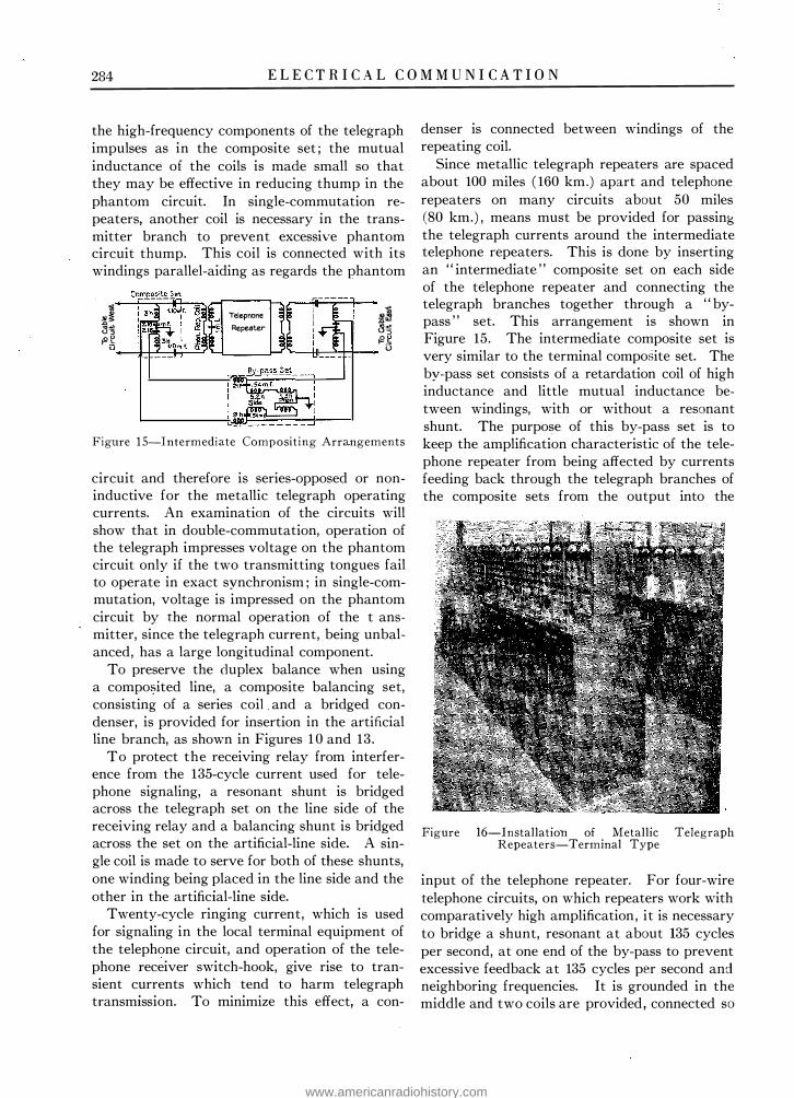
284 E L E C T R I C A L C O M M U N I C A T I O N
the high-frequency components of the telegraph impulses as in the composite set ; the mutual inductance of the coils is made small so that they may be effective in reducing thump in the phantom circuit. In single-commutation repeaters, another coil is necessary in the transmitter branch to prevent excessive phantom circuit thump. This coil is connected with its windings parallel-aiding as regards the phantom
lil J Telep none � ;§ � 3 Repeater 8 � � � � �
D._--!1--1-L---IH----r -... __ ___,- 'L--+ll-->--1--11-.... l3
Figure I S-Intermediate Compositing Arrangements
circuit and therefore is series-opposed or noninductive for the metallic telegraph operating currents. An examination of the circuits will show that in double-commutation, operation of the telegraph impresses voltage on the phantom circuit only if the two transmitting tongues fail to operate in exact synchronism ; in single-commutation, voltage is impressed on the phantom circuit by the normal operation of the t ansmitter, since the telegraph current, being unbalanced, has a large longitudinal component.
To preserve the duplex balance when using a compoi?ited line, a composite balancing set, consisting of a series coil . and a bridged condenser, is provided for insertion in the artificial line branch, as shown in Figures 1 0 and 13.
To protect the receiving relay from interference from the 135-cycle current used for telephone signaling, a resonant shunt is bridged across the telegraph set on the line side of the receiving relay and a balancing shunt is bridged across the set on the artificial-line side. A single coil is made to serve for both of these shunts, one winding being placed in the line side and the other in the artificial-line side.
Twenty-cycle ringing current, which is used for signaling in the local terminal equipment of the telephone circuit, and operation of the telephone receiver switch-hook, give rise to transient currents which tend to harm telegraph transmission. To minimize this effect, a con-
denser is connected between windings of the repeating coil.
Since metallic telegraph repeaters are spaced about 100 miles ( 160 km.) apart and telephone repeaters on many circuits about 50 miles (80 km.) , means must be provided for passing the telegraph currents around the intermediate telephone repeaters. This is done by inserting an " intermediate " composite set on each side of the telephone repeater and connecting the telegraph branches together through a " bypass " set. This arrangement is shown in Figure 15. The intermediate composite set is very similar to the terminal composite set. The by-pass set consists of a retardation coil of high inductance and little mutual inductance between windings, with or without a resonant shunt. The purpose of this by-pass set is to keep the amplification characteristic of the telephone repeater from being affected by currents feeding back through the telegraph branches of the composite sets from the output into the
Figure 16-Installation of Metallic Telegraph Repeaters-Terminal Type
input of the telephone repeater. For four-wire telephone circuits, on which repeaters work with comparatively high amplification, it is necessary to bridge a shunt, resonant at about 135 cycles per second, at one end of the by-pass to prevent excessive feedback at 135 cycles per second and neighboring frequencies. It is grounded in the middle and two coils are provided, connected so
www.americanradiohistory.com

E L E C T R I C A L C O M M U N I C A T I O N 285
that one will be effective for the side circuit and the other for the phantom circuit. For twowire telephone circuits the resonant shunt is unnecessary.
EQUIPMENT ARRANGEM ENTS
The terminal-type repeater is assembled as a complete unit at the time of manufacture and therefore the installation work consists only in
Figure 1 7-Metallic Telegraph Repeater-Terminal Type
arranging the repeaters in rows and connecting the line conductors, loops and batteries to the terminal strips. A typical installation is shown in Figure 16. A terminal and a through repeater are shown in Figure 17 and Figure 18, respectively.
The artificial-line equipment is mounted in the upper section of the repeater. Condenser switches, dial-type resistance switches, milammeters and miscellaneous keys are mounted on
a hinged panel of insulating material . On the back of the panel, immediately behind the dial switches are · the asscciated resistance units. The condensers which form part of the artificial line are stacked up in the space immediately behind the panel. The apparatus in the artificial line section is divided, so that the equipment which balances the cable pair is on the right side and that associated with the loop or ground-return section is on the left side.
Below the hinged panel is the keyshelf, on which are mounted the loop and line sounders and the monitoring telegraph key. At the rear
Fi gure 1 8-Metallic Telegraph Repeater-Through Type
of the keyshelf and fastened perpendicularly to it is a panel on which are mounted the switching keys for controlling the battery connections and for arranging the repeater to work under various circuit conditions. Underneath the keyshelf is .
www.americanradiohistory.com

286 E L E C T R I C A L C O M M U N I C A T I O N
a section for the condensers in the transmitter branch, the spark-killers and the vibrating circuit.
In the lower section of the repeater is a small mounting plate carrying the relays and the resistance units associated with the spark-killers and vibrating circuit. The lower end of this mounting plate is hinged so that - it may be swung forward, thereby giving access to con-
Figure 19-Rack-Mounted Metallic Telegraph Rep eaters-Through Type
nections of apparatus mounted on it. Below this is a terminal strip for the lines, batteries and the sending and receiving legs. Below the terminal strip and just above the floor are the retardation coils used in the transmitter branch.
A terminal repeater stands 62 in. ( 1.57 m.) high and occupies a space 14 in. (36 cm.) wide and 12 in. (30 cm.) deep and weighs about 220 lbs. ( 100 kg.) . The keyshelf is about 40 in . ( 1 m.) above the floor. On the top of the repeater is mounted the operator's " calling-in " lamp.
The floor-mounted type of through repeater has the same equipment assembly for both the east and west sides and these are practically the same as the portion of the terminal repeater which operates on the cable section. The equipment in the right-hand section of the through panel is for repeating signals from the east line to the west line, and the left vice versa. This repeater weighs about 230 pounds ( 105 kg.) and occupies _ the same space as a terminal repeater.
The rack-mounted through repeater was developed after experience with the floor-type had shown how little monitoring attention was required. For that reason the repeater was simplified by the elimination of the line meters and monitoring apparatus. A unit termed a " monitoring unit " is provided for a group of about seven repeaters, and it can be connected into any one repeater by means of cords and plugs. A rack-type repeater consists of three units, the relay and transmitter-branch unit, the balancing-composite unit, and the artificialline unit. Each of these-units consists of a steel panel with necessary apparatus, arranged for mounting on two upright standard I-beams, thus forming a " bay." Generally there are four repeaters, or three repeaters and a monitoring panel per bay. Figure 19 shows an arrangement of repeaters on racks having a height of about 90 in. (2.3 m.) . This type of repeater is supplied for single-commutation operation only, whereas both forms of " floor-mounted " repeaters are supplied for double-commutation operation. Considerable economy in first cost and maintenance is secured by the use of this rack-mounted equipment.
OPERATION AND MAINTENANCE
The metallic telegraph. repeaters require comparatively little attention on the part of repeater attendants. Under normal operating conditions one man takes charge of about 24 terminal repeaters or 40 through repeaters. The duties of of the repeater attendants consist mostly in maintaining satisfactory impedance balance of the artificial lines against the real lines. This balance is, of course, more exacting· for full-duplex operation than for half-duplex. The capacity balance varies only a slight amount. Variations
www.americanradiohistory.com

E L E C T R I C A L C O M M U N I C A T I O N 287
in resistance balance are caused by temperature changes, the average daily variation being about 6 per cent. The differential milammeter is used as an indicator in determining the resistance and capacity values required to obtain a balance.
The equipment maintenance work required for these repeaters is exceedingly small. For a typical installation of 200 repeaters, the adjustment of relays and general maintenance will necessitate not more than four or five manhours per day.
The maintenance schedule for adjusting the relays is somewhat variable, depending upon the type of circuit in which they are operating. In general, a 209-FA relay in a terminal repeater will give uninterrupted service for two to three months and in a through repeater for four to six months. The 215-A relays are adjusted about every three weeks when used as " break " relays and every six months operating as pole-changing relays.
With proper maintenance the transmission of the metallic telegraph system is such as to furnish high-grade half-duplex manual service for distances up to 2,000 miles (3 ,200 km.) or more. For the longer distances, the signal propagation time is. increased to an amount which makes the time required to " break " appreciable, but not objectionable. For half-duplex printer operation the metallic circuits are satisfactory for speeds up to about 19 dots per second, which corres-
ponds to about 300 characters per minute for the start-stop type of printer.
For full-duplex service, the metallic system affords very good transmission with manual operation for distances up to 1 ,000 miles or more. With careful maintenance of duplex balances, such a circuit is satisfactory for full-duplex printer operation at speeds up to about 16 dots per second, corresponding to about 260 characters per minute for start-stop printers and 385 for multiplex printers.
It is of interest to note that metallic circuits in cable are much more dependable and less subject to interruption than open-wire circuits. Such data as are available indicate that the annual lost time on a long metallic cable circuit is only about one-tenth as great as that on a ground-return polar-duplex circuit of the same length over open wire.
COMMERCIAL USE .
At the present time there are in operation in the Bell System about 55,000 miles (89,000 km.) of metallic telegraph circuits of this type of which 30,000 miles (48,000 km.) are worked on a composited basis. Approximately 20 per cent of the total mileage is operated full-duplex. There are now installed in the plant about 430 through repeaters and 1 ,050 terminal repeaters.
www.americanradiohistory.com

Voice-Frequency Carrier Telegraph System for Cables* By B. P. HAMIL TON and H. NYQUIST
Department of Development and Research, A merican Telephone and Telegraph Company
M. B. LONG and W. A. PHELPS Bell Telephone Laboratories, Incorporated
Synopsis: Carrier telegraph systems using frequencies above the voice range have been in use for a number of years on open-wire lines. These systems, however, are not suitable for long toll cable operation because cable circuits greatly attenuate currents of high frequencies. The system described in this paper uses frequencies in the voice range and is specially adapted for operation on long four-wire cable circuits, ten or more telegraph circuits being obtainable from one four-wire circuit. The same carrier frequencies are used in both directions and are spaced 1 70 cycles apart. The carrier currents are supplied at each terminal station by means of a single multifrequency generator.
ATELEGRAPH system has recently been developed which utilizes the range of frequencies ordinarily confined to tele
phonic communication. I t represents a special application of the carrier method of multiplexing telephone and telegraph circuits, which has already been described. 1
The new system has been designed particularly for application to four-wire telephone circuits. Installations have been made at New York and Pittsburgh, by means of which ten telegraph circuits are derived from one four-wire telephone circuit extending between these cities. Additional installations are planned and under way in which it is expected that a greater number of telegraph circuits will be obtained from each four-wire telephone circuit.
Experience in commercial service extending over a considerable period has fully demonstrated the effectiveness of this system.
GENERAL FEATURES
In a general way, the voice-frequency system resembles the high-frequency carrier system for open-wire lines, which has been described in the paper referred to above. The most important differences are that the voice-frequency system uses (1) a four-wire cable circuit instead of a two-wire open-wire circuit, (2) the same frequencies for transmission in both directions, (3)
* Presented at the Midwinter Convention of the A. I . E. E . , New York, N. Y., February 9-12, 1925.
1 Carrier-Current Telephony and Telegraphy, E. H. Colpitts and 0. B. Blackwell, Transactions, A. I . E. E. , 192 1 , page 205.
2S8
frequencies of the voice range rather than the higher frequencies used in open-wire carrier telegraph systems, (4) a multi-frequency generator instead of vacuum tube oscillators to supply the carrier currents and (5) fixed band pass filters instead of adjustable tuned circuits for segregating the several telegraph circuits.
Figure 2 shows in a simplified manner the essentials of the telegraph system under discussion. Reference to Figure 1 , which shows a four-wire telephone circuit,2 will make clear how the line portion of the telegraph system is derived from such a telephone circuit. As indica-
4·W\AE - 4·WIRF: TERMINATIN8 TUIMIRATIN$ i.:'.'.. j::El El � To � --=- To Telephone �·-1 Telephone
I I To ir-·
Telegrap -SenOers
Receive
b w I
TelJgra� --, ""�"· '
Figures 1 and 2
To Telegraph Receivers
ted in Figure 1 , the four-wire cable circuit uses two pairs of wires, one pair for transmission in each direction. When a voice-frequency telegraph system is applied to a telephone circuit the four-wire terminating sets, which normally ter· minate the circuit when used for telephone purposes, are removed and voice-frequency carrier telegraph equipment is substituted.
Signal Traced Through System. A general layout of the system is shown in Figure 3 and , in describing the operation, reference is made to this figure. The path of a signal from the sending operator to the receiving operator, on one of the ten two-way circuits will be considered.
2 Telephone Transmission Over Long Cable Circuits, A. B. Clark, Transactions, A. I. E. E., Vol. XLIJ, 1923, page 86 ; Electrical Communication, Vol. I , No. 3, 1923.
www.americanradiohistory.com

E L E C T R I C A L C O M M U N I C A T I O N 289
To produce a spacing signal the sender opens his key (shown at the left of the figure) which causes the sending relay to operate so as to shortcircuit the source of alternating current. To produce a marking signal the key is closed, which causes the sending relay to operate and to remove the short circuit. This permits the alternating current from the generator to flow freely into the filter. This sending filter is so
Sending Apparatus
�-
�==��!
Detector
channel . After passing through the rece1vmg filter the current enters the detector whose function is to convert the alternating current signals into direct-current signals which are capable of actuating the receiving relay. The receiving relay in turn transmits direct-current signals to the receiving operator's sounder or local relay.
This sequence of events is illustrated in the
To other ! Sending Circuits
T Sending band filter
I
Ampl ifier
To other j Receiving Circuits l
�
Figure 3
constructed as to permit relatively free passage of current frequency near the particular carrier frequency for which it is designed. For other frequencies the filter practically shuts off the current.
After passing through the filter the current mingles with currents from other channels and all are transmitted over the line as a resultant composite current. After flowing through the line in this mixed-up condition, the currents encounter the receiving filters which resemble the sending fiJters in that each transmits a relatively narrow range of frequencies in the neighborhood of the carrier frequency for which it is designed , and in that it acts substantially as an open circuit to other frequencies. By means of these receiving filters the currents are separated and each flows freely into its own
series of oscillograms of Figure 4, which shows the different forms of a group of telegraph signals in the 425-cycle channel, from the time when as d-c. impulses they flow through the sending relay windings, to the time when again as d-c. impulses they flow through the receiving relay and sounder circuit. It shows (a) their form in the sending relay and telegraph key circuit, (b) their translation into alternating current prior to passing into the sending filter, (c) their mingling with other similar impulses of different carrier frequencies after passing through the sending filter and on to the line as a single resulting wave flowing through the four-wire circuit, (d) their form after separation from the other channels by the receiving filter and (e) their final form in the receiving sounder circuit. The points where the oscillograms were taken
www.americanradiohistory.com

290 E L E C T R I C A L C O M M U N I C A T I O N
are shown in Figure 2 at a, b, c, d , and e, the cases being correspondingly denoted on the oscillograms.
Carrier Frequencies. The carrier frequencies are so chosen as to be odd multiples of a basic frequency of 85 cycles per second. The lowest frequency used is the fifth multiple of 85 cycles, that is, 425 cycles per second . Starting with this frequency, the carriers are spaced at 170-cycle intervals from their nearest neighbors, so that in the ten-channel system the uppermost
Figure 4
frequency is 1955 cycles per second. Each channel has assigned to it a range of frequencies 85 cycles above and below its own frequency. For example, the channel using a carrier frequency of 1 105 cycles has assigned to it the range between 1020 to 1 190 cycles. Choosing the carrier frequencies in this manner and placing each carrier midway in the band of frequencies assigned to it, has the effect of giving maximum discrimination against interfering frequencies generated in the various vacuum tube repeaters. As is well known, when a number of frequencies are transmitted simultaneously through a vacuum tube, currents which cause interference are generated due to small departures from linearity on the part of the tube characteristic. Some of the most important of these currents have frequencies equal to the sum and difference of the frequencies of the transmitted currents taken in pairs. Since the carrier frequencies are all odd multiples of the common frequency, 85 cycles, it follows that the sum and difference of the frequencies are even multiples of 85 cycles and therefore are located
midway between the carrier frequencies. This permits obtaining the maximum discrimination against these interfering frequencies by means of the filters, of which the characteristics are set forth below.
The number of carrier telegraph circuits which can be derived from a single four-wire cable circuit depends on the type of loading and, to a less extent, on the length of the circuit. I t has been mentioned above that at the present time ten two-way carrier telegraph circuits are operated simultaneously over a four-wire circuit between New York and Pittsburgh, a distance of about 400 miles (644 km.) . This is not, however, the maximum possible number of telegraph circuits which can be derived from the type of circuit used with this installation. Four-wire circuits which · are loaded with coils of small inductance transmit a wider range of frequencies and are already in use for telephone purposes. If such circuits were used instead of the type employed with the present installation, at least fifteen two-way carrier telegraph circuits could be obtained.
DESCRIPTION OF APPARATUS
Carrier Current Generator. Vacuum-tube oscillators are the source of the carrier current in carrier systems previously developed. In this system, however, all the carrier currents for the ten channels are obtained from a compact multifrequency generator driven by a motor built into the same housing with the generator.
The generator is an inductor-alternator designed to generate currents of ten different frequencies in ten different magnetic circuits electrically independent of each other. The machine has two field coils common to all the stators. The exciting current for these two windings is supplied by a storage battery. On the pole arc of each stator opposite each of the narrow disk-like rotors, mounted in a row on the shaft, are cut a number of slots, the number per unit length depending on the frequency to be generated. The stator windings for each circuit are placed in these slots. The rotor belonging with each stator has a corresponding group of slots cut in it but no windings are placed in these rotor slots. The result is equivalent to ten separate alternators except that the field excitation is common to all . The flux in any stator
www.americanradiohistory.com

E L E C T R I C A L C O M M U N I C A T I O N 291
tooth is greatest when a rotor tooth is opposite it and least when a rotor slot is opposite it. This variation in flux in the stator teeth as the rotor moves induces the voltage in the windings on these teeth. All the windings of a given stator are connected in series, so the total voltage generated in each stator is the sum of the separate voltages in the several windings.
A comparatively small generator is able to supply c�rrier currents to several ten-channel systems because, by using terminal repeaters or amplifiers (Figure 3) the amount of energy required to operate each telegraph channel is very small , and no channel produces any notice
able interference in another drawing current from the same stator winding. The terminal
FREOUENCY: CYCLES PER SECOND Figure 5-Characteristics of Filters
voltage of each stator is 0.7 volt and a current of 40 mils may be drawn from it without producing a change in terminal voltage sufficient to cause interference in any telegraph circuit drawing current from the same set of windings.
The driving motor is a small shunt-wound machine which receives its energy from a 24-volt storage battery. The speed of the motor is maintained accurately at 1700 rev. per min. by means of a centrifugal type of governor which controls the amount of current flowing through the shunt field winding. As the stability of the carrier frequencies depends on the constancy of the motor speed, it is necessary that the governor control the speed within narrow limits.
As a means of checking the speed of the generator an electrical frequency indicator is provided. This device is connected to and indicates the frequency of one of the generator circuits. As the frequency of an alternator is directly proportional to the speed it gives an
indication of the correctness of the speed and also of all frequencies produced by the generator.
Filters. Figure 5 shows the transmission characteristics of the transmitting and receiving filters. These filters are designed to transmit as wide a range in the neighborhood of the carrier frequencies as is necessary to secure the desired quality of transmission and at the same time exclude interfering currents, whether they be caused by foreign interference, direct transmission from other channels, or distortion in the repeater tubes. The principal interfering currents due to the latter are located 85 cycles on either side of the carrier frequencies. The
receiving filters have been designed to reduce these interfering currents to about 10 per cent of their original value.
In addition to screening out any undesired frequencies produced in the generator windings, the sending filters �ave the following more important functions. Each sending filter presents a high and comparatively non-dissipative impedance to the currents issuing from the other sending filters and also "rounds off" the impulses of the modulated carrier wave passing through it. The modulation of the carrier current by the sender's key produces what is called a "square" wave, that is, a wave containing not only the carrier plus and minus the frequency at which the key is operated but also the carrier plus and minus a large number of multiples of the frequency. Some of the component frequencies of this transmitted wave not only are found unnecessary in reproducing the transmitted signal at the receiving end but also lie within the range of adjacent channels and produce interference in them unless screened out by the sending filter in the channel in question.
The effect of the sending and receiving filters in "rounding off" the modulated carrier wave, that is, in screening out the objectionable components of the signal wave, is shown by the oscillograms of Figure 4. The combined effect of the two filters on the shape of the modulated carrier may be seen by comparing oscillograms (b) and (d) of this figure, which show respectively the appearance of the modulated wave before it enters the sending filter and after passing through the sending filter, over the line and through the receiving filter. Another interesting point in connection with these
www.americanradiohistory.com

292 E L E C T R I C A L C O M M U N I C A T I O N
oscillograms is the time lag due to the circuit which is shown by the relative differences in position of the two waves referred to above. Owing to the limitations imposed by the ordinary oscillograph all of the traces shown in Figure 4 were not taken simultaneously. This accounts for minor inconsistencies which are revealed by a careful inspection.
Detector. The detector receives alternating current signals from the line after the signals belonging to that particular channel have been selected by the receiving filter. I t consists of two vacuum tubes in tandem, the first tube (Figure 3) amplifying the received signals, and . the second converting them into direct-current pulses which operate the receiving relay. The receiving relay then repeats these telegraph signals into the receiving direct-current circuit which contains the receiving sounder.
To improve the operation of the receiving relay a device called an accelerating circuit or "kick" circuit, such as is used in open-wire carrier-telegraph systems, is interposed between the detector tube and the receiving relay. This circuit is obtained by introducing a transformer whose high-voltage side is connected in series with the detector tube and a winding of the receiving relay and whose low-voltage side is connected to another winding of the relay. When the current in the high-voltage side is constant, there is no current in the low-voltage side, but if the former current suddenly changes, as at the beginning or end of a marking signal, there is a sudden rush of current .in the low-voltage circuit which has the effect of causing the relay to operate promptly and positively.
Relays. As shown in Figure 3, the sending and receiving relays are of the polar type. These relays are identical and interchangeable with those used in the metallic and open-wire carriertelegraph systems.
Power and Testing Equipment. In the development of the voice-frequency carrier telegraph system, the central thought was the desirability of designing a system which would fit into the existing cable telephone and telegraph plant. It has been possible to use the standard voltages obtainable from the storage batteries in such plants without exception.
In line with the policy of simplifying this new system as far as possible, the amount of auxiliary
testing apparatus was reduced to a mm1mum. This policy has been assisted by the stability of the cable circuits and the use of a multi-frequency generator as a source of carrier currents. Only two pieces of special testing apparatus are used at each station, namely, the frequency indicator, and a thermocouple voltmeter for checking the alternating voltage in each generator circuit.
LINE AND REPEATERS As has been pointed out elsewhere in this
paper, the voice-frequency carrier telegraph system was designed primarily for use on smallgage, four-wire cable circuits. These circuits are loaded and provided with vacuum tube repeaters at 50 to 100-mile (80.5 to 161 km.) intervals, depending on the weight of loading used. The repeaters used in long toll circuits are similar to those described at an earlier date. 3 The characteristics of the long cable circuits used in voice-frequency carrier telegraph transm1ss1on have also been described in a more recent paper.4
EQUIPMENT FEATURES AND ARRANGEMENTS FOR GIVING SERVICE
The apparatus which is associated with each of the ten two-way circuits in this system has been segregated according to function and each group of apparatus performing the same function, such as the detector, has been mounted on a separate steel panel . Each one of these panels forms a unit in itself. This type of construction allows the substitution of new apparatus performing some particular function in the system without an expensive redesign. Thus, it is possible to install future improvements in the several cricuits of the system in an economical manner.
These unit panels are mounted on pairs of vertical I-beams and the combination is termed a "bay." The bays are of different heights, depending on the requirements of the office in which they are installed. Figure 6 shows a line-up of so-called low-type bays (about five feet high) in the Pittsburgh office. Each bay in this line-up contains sufficient equipment to
3 Telephone Repeaters, by Bancroft Gherardi and Frank B. Jewett, Transactions, A. I . E. E. , 1919, page 1287.
4 Clark, Loe. cit.
www.americanradiohistory.com

E L E C T R I C A L C O M M U N I C A T I O N 293
provide for the transm1ss10n and reception of signals at the Pittsburgh terminal of one of the
Figure 6
Figure 7
ten two-way telegraph circuits. Figure 7 shows. a line-up of similar equipment in the New York office, this layout differing from the one in
Pittsburgh in that it uses high instead of lowbays; Each bay in this line-up contains sufficient terminal equipment for two of the ten twoway telegraph circuits.
In addition to the bays described above there are three bays, carrying auxiliary equipment. This auxiliary equipment consists primarily of control and testing apparatus for batteries and carrier supply. Two of these bays, namely, the generator and carrier supply bays are shown in Figure 8 . This figure shows two of the multifrequency generators (one a spare machine)
Figure 8
described above, and the carrier testing equipment. The control equipment associated with these machines is mounted on the panels above the generator and the frequency indicator is mounted on .the panel to the right of this control apparatus.
SWITCHING AND MONITORING ARRANGEMENTS
The monitoring arrangements, which enable the attendant to check the quality of signals passing over a circuit or to trace trouble quickly and easily, are similar to those now in use in the open-wire carrier and metallic telegraph systems. These arrangements are described in
www.americanradiohistory.com

294 E L E C T R I C A L C O M M U N I C A T I O N
the paper on the metallic telegraph system 5 and, therefore, will not be given in detail here. In a general way it may be said that switches and meters are provided to connect the telegraph batteries to local apparatus, to provide either one-way or two-way service and to facilitate repeating to other telegraph systems.
CAPABILITIES OF SYSTEM
Field tests over the New York-Pittsburgh system have shown that each telegraph circuit derived therefrom is of high grade, allowing signal speeds of 3.1 to 40 cycles per second . That is. with machine sending, it is possible to transmit 140 to lf\O words per minute (five letters and a space per word) each \Vay over each telegraph circuit. Considerably higher speeds may. of course, be obtained by widening the frequency range assigned to each telegraph circuit.
The New York-Pittsburgh system may be used in connection with a multiplex printing telegraph system and three printer messages may then be sent simultaneously in either direction on each carrier circuit. Assuming 50 words per minute as the working speed for each of the three printers a total of lfiOO words per minute could he transmitted simultaneously in either direction over the ten circuits.
A simple numerical example will indicate what is technically possible by the application of this type of telegraph system to toll cables. A toll
5 Metallic Polar-Duplex Telegraph System for Long Small-Gage Cables, Electrical Communication, Vol. III, No. 4, 1925.
cable 2 5/8 inches (6.7 cm.) in diameter contains about 300 pairs of No. 19 B . & S. gage (0.91 mm.) conductors. Utilizing the phantom circuits this gives a total of 225 four-wire circuits. Counting 30 messages in each direction per fourwire circuit it is evident that it is techni�ally possible to transmit 6750 messages in each direction simultaneously.
The "break" feature of this system is satisfactory. It functions in a manner similar to that used with the metallic telegraph system. I t takes about 0 . 1 second to transmit a "break" signal over a 1000-mile ( 1 610 km.) circuit.
FIELDS OF APPLTCA TTON
It wil l he evident that while the foregoing description assumes that this system is applied to four-wire circuits, it could be readily applied to two-wire circuits by transmitting half of the carrier frequencies in one direction and the other half in the opposite direction. Furthermore, if the impedance characteristic of the line could be reproduced with sufficient accuracy in networks to balance the line at the repeaters , the same frequencies could be transmitted in both directions and as many of them could be so transmitted as the natural "cut-off" of the line would permit.
While the voice-frequency carrier telegraph system has been designed primarily for use on an ordinary telephone circuit, the system may be applied to carrier telephone or radio telephone channels without involving radical changes in either the telegraph system or the telephone circuit to which it is applied .
www.americanradiohistory.com

A New Keyboard Perforator for the Baudot Printing Telegraph System
By A. E . THOMPSON European Engineering Department, International Western Electric Company
THE invention by Emile Baudot in 1875, of his multiplex printing telegraph system, marks one of the most clear-cut
stages in telegraph history. The fact that in his native country, France, as well as in Great Britain, it is still in extensive use, and that modern multiplex systems have been developed on similar lines, is a tribute to the soundness of the principle it embodies.
A new step forward in the improvement of the Baudot system has been taken by Colonel Booth and Mr. Willmot, of the British Post Office, who have jointly invented an ingenious device which enables a Keyboard Perforator with only three rows of keys , together with a Keyboard lay-out in accordance with standard typewriter practice, to be used for the Baudot five-unit code.
As the Baudot system in its usual form is well known to most telegraph engineers, it will only be necessary here, as a preliminary, to describe briefly its operating features in order to explain the principles and outstanding advantages of the Perforator in which the new invention is embodied.
The Keyboard in general use for manual transmission has five piano-type keys, and the alphabet is signalled by depressing these keys according to the table shown in Figure 1. The first three fingers of the right hand control the keys 1, 2 and 3, and the first two fingers of the left hand, the keys 4 and 5. The same permutations are used for figures, and for other symbols, as for the alphabet. This is made possible by an inversion mechanism in the receiving printer which shifts the typewheel into the desired position upon receipt of a control signal (" Figure space ," or " Letter space,") much in the same way as on the ordinary typewriter.
The mechanism by which the signal impulses are transmitted over the line is shown diagramatically in Figure 2. The revolving distributor brushes, DB, successively connect the segments of the outer ring to the adjacent continuous ring, and thus to the line. Each of the
295
CHARACTER 5ELECTEO
CURRENT IMF'UL.5ES
l<EY:S OPERATED
LOWER CASE:
UPPER' CASE
I 2 3 4 5 5 4 I 2 3
A --- --- - 1 -
---r·,.-- - •
• • B --- ---- 8------
--- - - - -
C --- ----S---- -"""" --- ----- • • • C--- --�-0- - -�..-.-.l""""..1- - • • • •
E.--- ---- 'Z---1_.--...... • F'--- -- --!:--- -� .... .Jm•lllll.,.....J • • •
G---- - - - 7- - ---""" --
- - - - - • •
H--- ---.?::!..--· --""" -,.... - - -
!--- ----.2.--- ;.... ---I"'"" - ---- • • • - • •
J --- -- - 6-------..... - • • K.--- ---( - - ---"""""" -- ----- . . • L.; - - - - - = - ----- - · · • •
M--- --- )-- - - - - • • •
N --· - - -NCI ---- • • • •
Q --- ---- 5 --- �lllllfl-:_ ... _..1 - • • • p --- --%-------· Q --- - - - / - - -11111--.._..Ja.-.1111
- · • • • • • •
R--- --- - - -L."""J."""..Ja•� - · - · 6--- -- --;--
---
-- ---
T--- --- ! --- --
-'""'
- ---u --- --- 4--- ---
------
- ·
, -v --- -- - -- -- -w --- --- ?--- ---"""'- -- --x --- - - -,--- --
--- ---
y--- ---a-------
-
• •
- · -
. -
-
-2--- - - - · - - - -- --- • -F"IGURE SPACE --
LETTER 5Pi'CE • -
- - ·
•
•
t _ _ i _ _ _ . _ _ _ _ -
-'1" -- - --- ,,, ---i.i.••rn ........ '" 11111 • •
E;
_
_ --- �---r-i--.----Figure 1
-
• • • •
• • • • • • •
• • •
• • •
•
• •
www.americanradiohistory.com

296 E L E C T R I C A L C O M M U N I C A T I O N
five segments on the outer ring is connected to a signaling key at one end of the line and to an electro-magnet in the receiving printer at the other end. The distributor brushes at the two stations are driven in unison and in phase, so that at every revolution the signaling keys are connected to the line at the same instant as the printer electro-magnets are connected to the armature of the receiving polar relay.
As the keys normally rest against the negative or " spacing " hushar, the armature of the receiving relay is held in the position shown, and the printer is not actuated.
Fig ure 2-Principle oi Baudot Transmission
When one or more of the keys are depressed, a permutation of five positive and negative impulses is transmitted to line, the corresponding printer electro-magnets are energized, and the desired character is recorded.
With this method of transmission it is neecessary first to proYide a warning signal, so that the operator may know at what instant to depress the keys. N ext, it is necessary to ensure that the operated keys do not rise again until the distributor brushes have passed over the last sending segment. These requirements are met by a ' · Cadence " mechanism. When the keys are depressed, they are held mechanically by five hooks, until the local brush passes on to the cadence segment CS. At this instant an electro-magnet in the keyboard is energized, and its armature releases the keys and gives a warning click to the operator. As soon as the local brush passes off the cadence-segment, the armatµre falls back and the keys which have been depressed are again locked.
When automatic transmission is used, the five-key keyboard is replaced by a tape-operated transmitter and a keyboard perforator. This
method of transm1ss10n has important advantages both from the standpoint of line economy and operator ouput.
With direct keyboard transmission, every time the operator stops, to sign and " time " a telegram, the line is idle. With automatic transmission, however , as the operator no longer transmits direct to line, the actual traffic handled more closely approaches the theoretical traffic-carrying capacity of the system. The operators, moreover, are not required to perform the mental task of translating the signals into the Baudot code and to set up the combinations on the keyboard. As this work is done mechanically , the operators need only possess typing skill and, therefore, instead of restricting the speed of the Baudot system to 30 words per minute per channel, as is at present necessary because of operator limitations, it should now be practicable to increase the speed to 35 or 40 words per minute without imposing any additional strain upon the staff.
The Automatic Tape Transmitter, Figure 3 , consists essentially of five contact-levers con-
Figure 3
trolled by a paper tape previously prepared by means of the keyboard perforator. The operation of the mechanism is as follows :-
When the local distributor-brush passes over the cadence-segment, the transmitter electromagnet is energized and its armature first depresses the five selecting pins SP, Figure 4, and then the rocker bar RB. The rocker-bar raises the pawl P, and thus rotates the starwheel SW, stepping the tape forward one character. All the contact levers now rest against the " spacing " bus-bar. Immediately the electro-magnet is de-energized, the selecting pins
www.americanradiohistory.com

E L E C T R I C A L C O M M U N I C A T I O N 297
are free to rise, but they can only do so if there is a hole for them to pass through in the paper tape. The pins which do pass through the tape raise their horizontal arms, HA , and their cor-
Figure 4-Automatic Tape Transmitter
responding contact-levers, CL, are thus moved over to the " marking " bus-bar : the springs, S, being stronger than the contact-lever springs, CLS. In this way positive or negative linebattery is connected to the five sending seg-
ments, and the signal permutation is transmitted to line in the manner ah:eady described.
The general appearance of the keyboard perforator is shown in the photograph, Figure 5 , and the novel feature, which it is one of the main objects of this article to describe, is that the machine can perforate two entirely different arrangements of the five unit code. The necessity for this is due to the fact that in the Baudot code the " Upper case " and " Lower case " characters do not correspond to standard typewriter practice and, therefore , if each key controlled only one signal permutation, the figures would be ;,cattered throughout the keyboard instead of appearing in proper sequence in the third row of keys. From an operating standpoint, such a keyboard layout would obviously have serious disadvantages. The difficulty could, of course, be easily overcome by providing an extra row of keys, but in the new perforator this undesirable feature is avoided .
It is also to be observed that each character is perforated across a tape only } A· of an inch
Figure 5
www.americanradiohistory.com

298 E L E C T R I C A L C O M M U N I C A T I O N
wide, and as the feed forward for each is only lo of an inch, the Perforator is economical in the use of paper.
Each operating key is mounted at the end of a pivoted key-lever, supported at its center by a� spiral spring, Figure 6. Lying transversely
V\rhen the " Figures " key is actuated, the carriage is moved one-eighth of an inch to the right and the keys then perforate the tape as s hown at F, Figure 7, as their key levers now have entirely different permutations of notches presented to their lower edge. Thus the keyboard
Figure 6
beneath the key levers is a movable carriage in which five code bars are mounted, their function being to select the punches required to perforate the paper tape. The code bars are notched in such a way that every key lever operates a different combination of code bars. Furthermore, two different permutations of notches are allotted to each key lever, the one effective depending upon the position of the movable carriage. For example, when the keys are operated with the carriage in its normal or " Letters " position, the tape is perforated as shown at L, Figure 7.
is capable of perforating two different arrangements of the five unit code.
The code-bar carriage is moved into the desired position by operating the " Letters," or " Figures " keys, the levers of which engage a corresponding knife-edge mounted upon the frame of the carriage, Figure 8. The lateral movement of the carriage is controlled by a spring-mounted jockey-roller, JR, fastened to the carriage guide-rods, and shock is avoided by suitable buffers. Each code-bar is spring supported and is carried by two horizontal links, H L, pivoted to one end of the carriage. This
www.americanradiohistory.com

E L E C T R I C A L C O M M U N I C A T I O N 299
arrangement ensures a perfectly perpendicular movement of the code bars. In addition to the five code bars mentioned, a sixth or " universal " bar, is mounted beneath the key levers. This
hinged to a selecting finger, SF, normally resting between the punch-hammer, PH, and one of the five punch-pins, PP. The punch-hammer is operated by the punch-magnet, P kl, and
L
F
8 8 0 0 0 0 0 0 0 0 0 0 0
0 0 0
0 0 0
0 0 0 0 0 0
0 0 0 0 0 0 0 0 0 0 0 0 0 0 0
0 0 0 0
0 0 0 0 0 0 0 0 0 0 0 0 0 0 0 0 0 0 0 0 0
8 0 0 0 0 0 0 0 0 0 0 0 0 0 0 0
0 0 0 0
0 0 0 0 0 0 0 0 0 0
0
0 0 0 0 0 0 0 0 0 0 0 0 0 0 0 0 0 0 0 0 0 0 0 0 0 0 0 0 0 0 0 0 0 0 0 0 0 0 0 0 0 0 0 0
Figure 7
CAR:'KIACE MOVEMEf'IT CONTirOl-
- 01FC:ECTIOl':t OF CAR'R"IAO£. TR"AV!tl,... WMEN ' FlCUi<:'E.'5 " KEY 15 OEPKE:SSl!!:O
Figure 8
0 0 0 0 0 0 0 0 0 0 0 0 0 0 0 0 0 0 0 0 0 0 0 0 0 0 0 0 0
0 0 o g o 0 0 0 0 0 0 0 0 0 0 0 0 0 0 0 0
0 0 0 0 0
0 0 0 0 0 0 0
0
0 0 0 0
0 0 0 0 0 0 0 0 0 0 0 g g o
code bar is actuated every time a key is depressed, and it serves to close two contacts in the circuit of the punch-magnet.
Each of the five selecting code-bars controls a pivoted link, SL, the upper end of which is
its upward movement is such that it can only force the punches through the tape when a selecting finger rests in its pa th . It will be observed that the function of the selecting mechanism is to withdraw the selecting fingers from
www.americanradiohistory.com

300 E L E C T R I C A L C O M M U N I C A T I O N
beneath punches not required to perforate the tape.
Each punch is supported by a spring, PS. One end of this spring is fastened to the punchblock, and the other end rests against a stop. When a punch is forced through the tape its spring restores it as soon as the punch-hammer is retracted . A sixth punch-pin, less in diam
eter and longer than the others, is forced upwards every time the punch-hammer is actuated . This punch perforates the small feed-holes near the center of the tape, which are required for the propulsion of the tape through the Perforator, and ultimately through the Transmitter. The feed-holes are engaged by a star-wheel controlled hy a ratchet wheel mounted
on the same shaft. When the punch-magnet is
operated , the feed-pawl (inset Figure 8) is withdrawn out of engagement with the ratchet
wheel , and when it moves forward again it rotates the ratchet-wheel and thus advances the tape in readiness for the next character.
In the event of an operator's finger slipping and inadvertently depressing two keys simultaneously, it is possible to correct the tape.
As more than the required number of selecting fingers will in that event have been withdrawn, the tape will have been perforated with fewer holes than the particular character requires. To make a correction, a " back space " key is operated which disengages the feed-pawl from the ratchet-wheel, by rasing the pin P, and then causes the back-space pawl to engage the star-wheel and thus to " step hack " the tape.
www.americanradiohistory.com

/11rer11a1io11al 'Wesf'ern Electric Company I N CORPORAT E D
Head Offices European General Offices 195 BROADWAY
NEW YORK, U. S. A. CONl'IJAUGHT HOUSE
ALDWYCH, LONDON, ENGLAND
Affiliated Companies Western Electric Company, Limited . . . . . . . . . . . A ldwych , London, England
Branches : Birmingham, Cardiff, Glasgow , Leeds, Man-chester, N ewcastle-on-Tyne, Southampton, D ublin, Cairo, Johannesburg, Singapore.
Bell Telephone Manufacturing Company . . . . . . . . . . . . . . A ntwerp, Belgium
Branches : Berne, The Hague, Brussels, Riga, Reva!.
Le Materiel Telephonique . . .
Telefonos Bell, S . A . . .
. . . . . . . . . . . . . . . . . . . . . . Paris, France
Madrid, Spain Western Electric I taliana . . . . . . . . . . . . . Milan, Italy
Branches : Rome.
Western Electric Norsk Aktieselskap . . . . . . . . . . . . . . Oslo, Norway
Vereinigte Telephon und Telegraphen Fabrik . . . . . Vienna, Austria
United I ncandescent Lamps and Electrical Company, Limited Budapest ( Ujpest) , Hungary
Western Electric Company (Australia) Limited . . . . . . . . . Sydney, A ustralia
Branches : Melbourne, Wellington.
N ippon Denki Kabushiki Kaisha . . . . . . . . . . . . . . . . . . . . . . . . . Tokyo, Japan Branches : Osaka, Dalny (Manchuria ) , Seoul (Chosen)
Sumitomo Electric Wire & Cable Works, L td . . . . . . . . . . . . . . . Osaka, Japan
China Electric Company, Limited . . . . . . . . . . . . . . . Peking, China
Branches : Shanghai, Tien tsin
Northern Electric Company, Limited . . . . . . . . . . . . . . . . . . Montreal, Canada Branches : Quebec, Halifax, Toronto, London (Ontario) , Hamilton, Windsor, Winnipeg, Calgary, Regina, Vancouver
Compania 'vVestern Electric Argentina . . . . . . . . . . . Buenos Aires, Argentina
Sales Offices and Agencies Throughout the World
To those interested in better communication the I nternational Western Electric Company and its Affiliated Com
panies offer the facilities of their consulting engineering departments to aid in the solution of problems in Telephony Telegraphy and Radio.
Printed in U. s. A.
www.americanradiohistory.com


