Aquila Cars A/S reserves the right to make pricing and specification changes as and when necessary. Any changes will be notified at quotation. All prices are excluding VAT. Aquila Cars A/S cannot be held responsible for any errors in printing. Nomenclature Updated: 31/01/2019 Version: 3.3
Transcript
Aquila Cars A/S reserves the right to make pricing and specification changes as and when necessary. Any changes will be notified at quotation. All prices are excluding VAT. Aquila Cars A/S cannot be held responsible for any errors in printing.
Nomenclature
Updated: 31/01/2019 Version: 3.3
1 Version 3.2 31/1 2019
The technical regulations are based upon the following: Parts for Aquila Synergy Cup are represented in the nomenclature and are split into three categories:
Category A
No modifications are permitted. All parts within this category must remain in their original positions and fulfil the function/s for which they were originally intended. These parts must be genuine Aquila Cars A/S components. These components must be approved and marked by Aquila Cars A/S using the Aquila hologram badge.
Category B Parts are to be treated as ‘Category A’ unless modifications or prescriptions are indicated in the regulations or in Aquila Cars A/S nomenclature. These components must be approved and marked by Aquila Cars A/S using the Aquila hologram badge.
Category C
The parts stated within this category are considered to be unrestricted, on the express conditions that:
1. The function for which they were originally designed is not deviated. 2. That it does not fulfil any additional function. 3. It is located in the same place as the original component.
Areas to be noted:
The set of items or subassemblies that make up a part or assembly are deemed to belong to the same category as the part or assembly in question.
Scrutineering may consist of comparing that part to be checked against a similar genuine Aquila Cars A/S component. All parts not shown in the technical regulations are systematically classed in category ’A’ unless specified otherwise above. In addition all genuine Aquila Cars A/S components will be checked for their badge of originality which must not be damaged or covered in any way.
The pictures published in this document only aim at making the nomenclature easier to understand. These pictures cannot be used for any comparison with the original vehicle parts.
2 Version 3.2 31/1 2019
Nuts, screws and bolts
Nuts, screws and bolts are classed within ‘Category C’ unless mentioned in the nomenclature, and can be removed if desired.
Washers
All washers are classed within ‘Category C’ unless mentioned in the nomenclature, and can be removed if desired. It is allowed to add a washer only to improve mechanical assemblies. The use of a washer for setting purposes is forbidden, unless specifically mentioned in the nomenclature.
Electrical loom
The electrical loom is classed within ‘Category B’ and must be a genuine Aquila Cars A/S item. The loom may be protected by non-retractable sheathes.
Protection
It is permitted to add protection of any kind over mechanical elements of the car unless specifically stated in the nomenclature. These protections must have the sole function of protecting the items contained within their surface. For driver safety, it is allowed to add protection within the cockpit on the condition that these additional items are easily removable without the use of tools.
Supports
It is allowed, unless mentioned in the nomenclature, to add various types of support to improve the fitting of tubes, hoses and electrical looms within the vehicle. Fitting of these supports must not require the modification of any components. The sole function of these supports must be maintaining the components for which they have been added and can only be made of tape, tie-wraps or other non-constructive material.
Bodywork
It is allowed to modify the bodywork elements and their respective supports but only in order to aid in the fitting and correct assembly of these components. Adhesive tape may be put on the bodywork, but in all circumstances its only purpose must be to protect or fasten the component to which it is applied.
3 Version 3.2 31/1 2019
5.0 ENGINE 5.1 GENERAL
Engine protests will cost 6000 Kr. Before any investigation takes place, the engine will be investigated by an independent party set out by Aquila Cars A/S. Please refer to Appendix 1 for further details about Engine protests.
Engines will be mounted upright, and aligned East West in the chassis. The addition of any material be it metal, plastic or composite etc. by any means be it welding, bonding, encapsulation or
encasement to any component is prohibited. The only exception to this, are the approved components from Aquila Cars A/S which can be found in the ‘Engine and Transmission Assembly’ section of the Aquila Synergy Nomenclature. Specific repair of the mounting points of the cylinder block to the transmission or chassis are allowed, whilst other casting repairs may be allowed with prior written approval of the Technical Commissioner responsible for the Formula.
Balancing of reciprocating and rotating parts is permitted only by removal of metal from approved locations so set out by the manufacturer.
It is prohibited to change the water pump, fan and generator drive pulleys and their retention bolts, washers and belts. No under drive pulleys are allowed.
The generator must remain unchanged. No under drive pulleys allowed. The use of non-standard replacement fasteners, nuts, bolts, screws, studs and washers which are not connected with, or
which do not support, any moving parts of the engine or its compulsorily retained accessories is permitted. Freedom granted to any fastener does not allow for freedom to move items relative to each other.
The use of thread locking compounds is permitted. Gaskets are free except for the cylinder head, intake and exhaust system gaskets which must be standard Toyota
components for the engine, and inlet manifold to cylinder head gasket which must be of production thickness. Any process of cleaning may be used on any component providing the surface finish must remain standard, is not affected. The exterior surfaces only (of the complete engine assembly) of ferrous parts and the exterior surface of the Plastic Rocker
Cover may be protected by paint or similar means. No internal component or surface may be coated by any protective finish. Other Toyota produced aluminum components may be protected only on their external surfaces by a transparent clear varnish, or similar.
4 Version 3.2 31/1 2019
Part numbers quoted were correct at the time the regulations were drafted. However, as with all companies, the Toyota Motor Company reserve the right to make changes to components for reliability or other reasons. Consequently the part numbers quoted may be superseded by later released parts. Full Toyota part numbers do not necessarily appear on all parts.
It is permitted to use gaskets from Citroen or Peugeot, as long as the stock Toyota dimensions are retained. These must not be machined in any way.
It is prohibited to alter the engine mounts in any way to lower or raise the engine, or shift it to either side in the chassis.
5.2 PERMITTED ENGINE The only permitted engine is the Toyota 1KR-FE from the first gen Toyota Aygo.
5.3 INDUCTION The air cleaners cannot be changed to other types than those offered from Aquila Cars A/S. The inlet manifold and throttle body system must be the Aquila Synergy system. It is prohibited to alter the induction trumpet length and dimensions by any means. Only stock thickness gaskets can be
used, and only the stock number of gaskets can be used. If any updated induction systems become available from Aquila Cars A/S, these must be retrofitted to older vehicles.
5.4 EXHAUST SYSTEM It is prohibited to change the exhaust system and manifold. A mandatory silencer from Aquila Cars A/S must be fitted. If any updated exhaust systems become available from Aquila Cars A/S, these must be retrofitted to older vehicles.
5.5 CYLINDER BLOCK It is permitted, as means of repair, to replace damaged cylinder bores with cast iron cylinder liners, all too standard
dimensions. It is permitted to machine cylinder liners to maintain deck height. The cylinder bore diameter can be a maximum of 71,013mm.
5 Version 3.2 31/1 2019
5.6 CYLINDER HEAD (INCLUDING VALVES AND VALVE GEAR) Non-standard rocker covers are prohibited. Standard valve spring retainers must be used, only stock valve springs are permitted. Shims are permitted. Valve lifters must be stock Toyota parts. No machining or lightening is allowed. Valves must remain standard, no re-profiling or polishing is permitted. The original 30 degree inlet seat angle, and 45 degree
exhaust seat must be maintained. Maximum valve diameter, inlet 27.5mm; exhaust 23.5mm. Overall length inlet 88.50 ± 0.5mm. Overall length exhaust 89.10 ± 0.5mm. Valve stem diameter must be 5mm. Valve stem seals must be fitted. Maximum port diameter at manifold face: inlet 40mm*28mm. Inlet and exhaust port diameter cannot be changed in any way. It is permitted, as means of repair, to replace damaged valve guides and valve seats by replacement valve guides and valve
seat inserts, to all standard dimensions. The valve seats cannot protrude into the combustion chamber if they are to be changed - they must be mounted flush to the combustion chamber. No machining allowed.
Valve clearance must be minimum 0.145mm inlet and 0.275mm exhaust. The valve seat width must be minimum 1.2mm intake and 1.11 exhaust, and maximum diameter is 27.3mm inlet and
23.2mm exhaust.
5.7 COMPRESSION RATIO The maximum compression ratio will be controlled as follows: Maximum compression ratio is 10.5:1. It is prohibited to make any changes to the compression chamber, to do any machining or polishing, to move the valves
relative to each other, or to do any deschrouding of the valves. The cylinder head minimum thickness is 129.8mm. Standard Toyota cylinder head gasket Part No. 1111540060, or Victor Reinz Part No. 61-53425-00, metal multilayer must be
used. It is prohibited to remove metal layers from the gasket. minimum compressed thickness is (0.5mm), ii) Pistons must not protrude above the cylinder block face at TDC. The cylinder block surface may be machined, as long as
the compression is not raised past 10.5:1.
6 Version 3.2 31/1 2019
5.8 CAMSHAFT The only permitted camshaft is the Toyota production camshaft for the 1KR-FE engine. The camshaft must remain entirely unmodified. It must be fully manufactured and ground to the Toyota Motor Company
profile. It is prohibited to grind from blanks, regrind or re-profile. Shot peening, shot blasting or polishing are prohibited. The camshaft profile is defined by determination of lift (L-l) against a flat footed follower at various angles (Ø). Maximum lift
at all points on the camshaft must not be exceeded. The specified lift is cam lift, not valve lift, which is cam lift minus valve clearance. Standard Toyota tolerances apply to the following camshaft lift.
5.9 PISTONS Pistons must be standard Toyota production pistons for the 998cc engine, unmodified in any way except for balancing and
as detailed. All three piston rings must be fitted, piston rings must be standard production or similar replacements, i.e. the compression
rings must be one piece, with conventional plain gaps, the oil control rings must be either single piece twin land type or apex three piece (two rails and an expander).
The minimum weight of the piston, piston rings, gudgeon pin, connecting rod, rod bolts and bearings shells are 582g.
5.10 CONNECTING RODS Connecting rods must be standard Toyota parts Machining is permitted to remove metal from the balancing bosses on the
big-end cap and at the little end, with the sole purpose of balance. Polishing is prohibited. It is prohibited to change the centres of the connecting rod by machining, to change the length of the connecting rod.
7 Version 3.2 31/1 2019
5.11 CRANKSHAFT A standard crankshaft must be used. Spot Machining to achieve balance is permitted. Crankshaft pulley must remain stock. No under drive pulley allowed. It is not permitted to alter the number of bearings or fit bearings of less than standard production width. Standard oversize and undersize bearings are permitted. The minimum weight of the crankshaft is 8.620kg. It is prohibited to grind the crankshaft on different centers to raise the stroke. The maximum permitted stroke is 84mm.
5.12 FLYWHEEL AND CLUTCH The flywheel and clutch assembly must be standard components. To achieve minimum weight and balance, material may be
removed from the originally machined surfaces, rim/flange Etc… For rectification, the clutch mating face may be resurfaced. Cast surfaces must remain in original condition. It is permitted to use a similar pattern replacement clutch (i.e. conventional single diaphragm spring) friction plate with shock absorber springs. Organic friction material only is permitted.
Racing clutches are prohibited. Flywheel bolts are free. It is permitted to secure the starter ring to the flywheel. Flywheel and clutch assembly minimum permitted weight: 9.475Kg. (Including all flywheel and crankshaft mounting bolts). It is prohibited to move the location of the flywheel in any way on the crankshaft.
5.13 LUBRICATION SYSTEMS It is prohibited to make any change to the oil system. With the exception of the mandatory relocating of the oil filter as set out
by Aquila Cars A/S.
5.14 COOLING SYSTEM It is prohibited to make changes to the cooling system. The cooling liquid must contain a minimum of 30% ethylenglucol, and a maximum of 50%.
8 Version 3.2 31/1 2019
5.15 FUEL PUMP Only the Toyota Aygo fuel pump for the engine is permitted.
5.16 IGNITION SYSTEM Only the stock Toyota ignition systems are allowed. Spark plugs are free of choice as long as the stock dimensions are retained.
5.17 ENGINE MANAGEMENT Only the engine management system from Aquila Cars A/S is allowed. It is prohibited to alter the Electronic Control Unit (ECU) maps, move the placement of the engine ECU trigger system or the
crankshaft trigger wheel. It is prohibited to use engine sensors, and fuel injectors, other than the standard Toyota components for this engine.
9 Version 3.2 31/1 2019
Vehicle Setup
Weight It is at the discretion of the championship organisers to weigh competition vehicles at any time during a race-weekend, the weight of the
car without the driver, must not be less than 420 Kg. The weight of the car inclusive of the driver, must not weigh less than 510 Kg. If a car needs to use ballast plates to full fill the rules above, it can only be with original Aquila Cars A/S ballast weight adjusting plates.
No other weights will be accepted.
Setup The camber angle on both front and rear corners of the car, can be adjusted. There must be 0 (zero) to 4 (four) original Aquila adjusting
shims, mounted in each corner. No more – no less. The Caster angle on both front and rear corners of the car, is NOT allowed to adjust. The Toe-in angle on both front and rear corners of the car, can be adjusted without any restrictions. The Ride Height of both front and rear of the car, can be adjusted without any restrictions. Tyre pressures are not restricted.
10 Version 3.3 31/01/19
Crashbox
A B C 1-01 X 1-02 X S-11 X
11 Version 3.3 31/01/19
Crashbox – Part Numbers
Item Number Part Number Description 1-01 SC-01-035-0314 Front Towing Eye 1-02 SC-01-035-0409 Crashbox S-11 Bolt Set: Mounting Crashbox to Chassis
12 Version 3.3 31/01/19
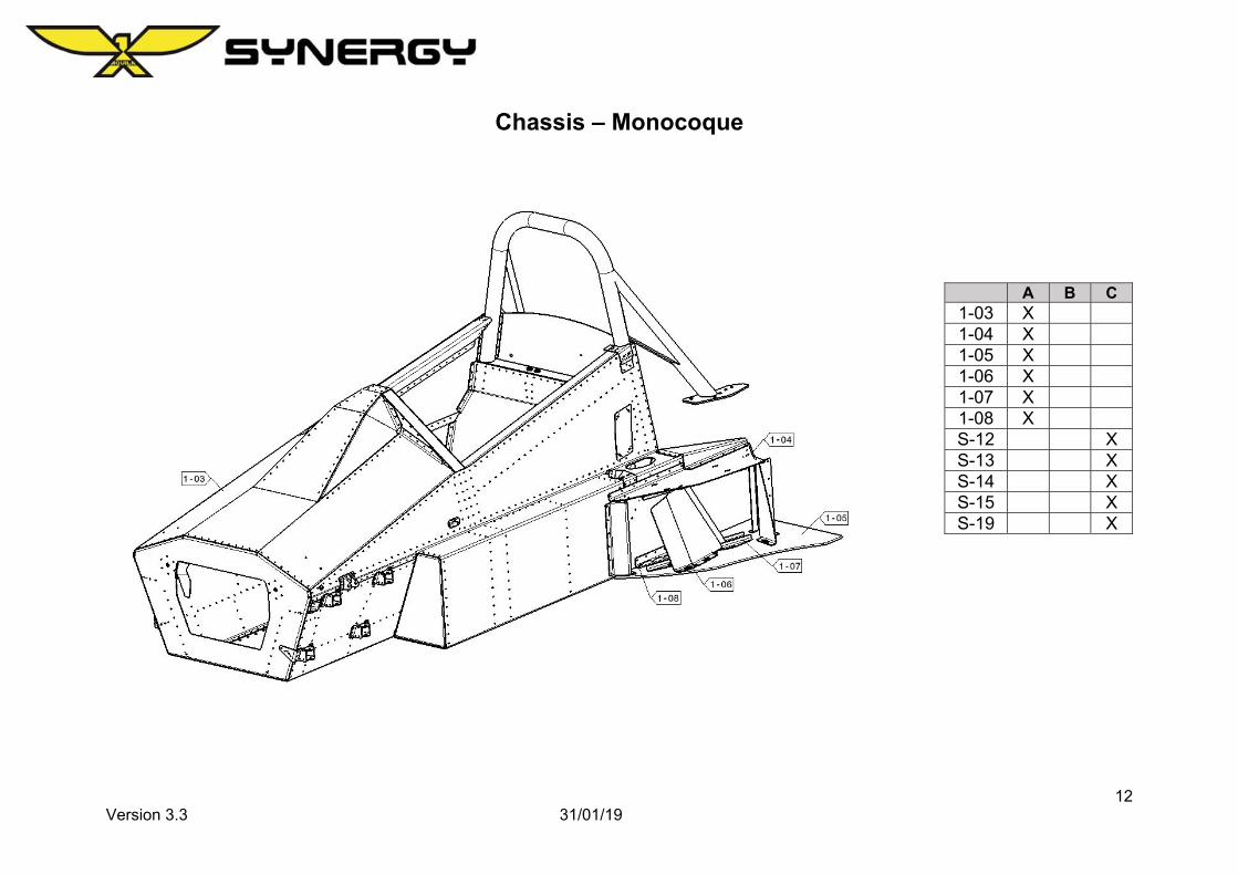
Chassis – Monocoque
A B C 1-03 X 1-04 X 1-05 X 1-06 X 1-07 X 1-08 X S-12 X S-13 X S-14 X S-15 X S-19 X
13 Version 3.3 31/01/19
Chassis – Monocoque – Part Numbers
Drawing Number Part Number Description 1-03 SC-01-001-0410 Monocoque Chassis 1-04 SC-01-058-0015 Radiator Housing 1-05 SC-01-058-0374 Radiator Duct Floor
1-06 SC-01-058-0382 Central Duct Left SC-01-058-0383 Central Duct Right
1-07 SC-01-058-0384 Radiator Right Angle Locator
1-08 SC-01-058-0388 Radiator Floor Mounting Strip Left SC-01-058-0389 Radiator Floor Mounting Strip Right
S-12 Bolt Set: Rear Roll Hoop to Subframe S-13 Bolt Set: Radiator Floor S-14 Bolt Set: Radiator Centre Duct S-15 Bolt Set: Right Angle Locator through Floor S-19 Bolt Set: Right Angle Locator through Housing
1-03 Minor repairs may only be completed by Aquila Racing Cars A/S, The repair must be accompanied with a certificate of authenticity for the moncoque life.
14 Version 3.3 31/01/19
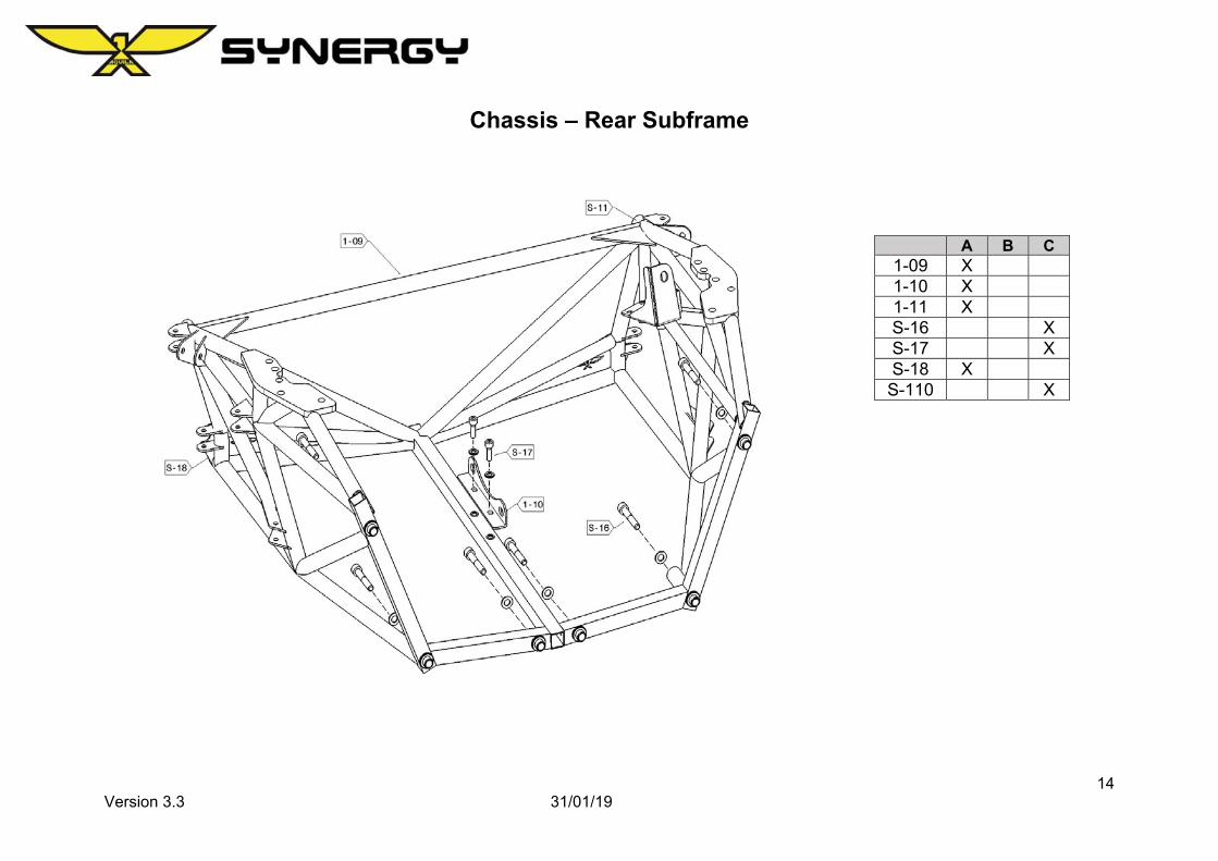
Chassis – Rear Subframe
A B C 1-09 X 1-10 X 1-11 X S-16 X S-17 X S-18 X
S-110 X
15 Version 3.3 31/01/19
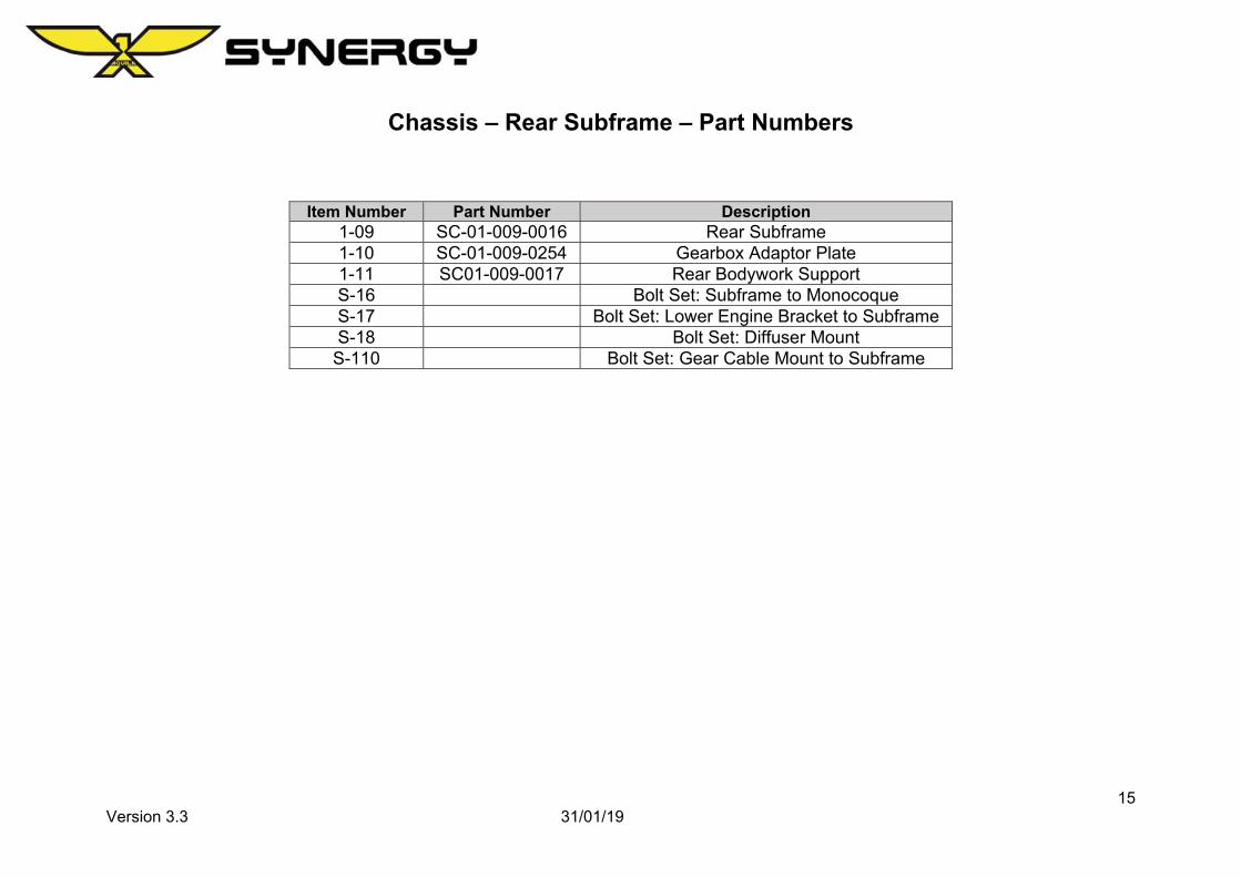
Chassis – Rear Subframe – Part Numbers
Item Number Part Number Description 1-09 SC-01-009-0016 Rear Subframe 1-10 SC-01-009-0254 Gearbox Adaptor Plate 1-11 SC01-009-0017 Rear Bodywork Support S-16 Bolt Set: Subframe to Monocoque S-17 Bolt Set: Lower Engine Bracket to Subframe S-18 Bolt Set: Diffuser Mount
S-110 Bolt Set: Gear Cable Mount to Subframe
16 Version 3.3 31/01/19
Suspension – Front Corner
A B C 4-01 X 4-02 X 4-03 X 4-04 X 4-05 X 4-06 X 4-07 X 4-08 X 4-09 X 4-09 X 4-11 X 4-23 X S-41 X S-42 X S-43 X S-44 X S-45 X S-46 X
4-04 The hub must be an original OEM hub. 4-06 Brake pads must conform to championship organiser regulations. 4-07 Caliper must be kept in original condition. 4-09 Tyres must conform to championship organiser regulations.
18 Version 3.3 31/01/19
Suspension – Front Wishbone
A B C 4-13 X 4-15 X 4-17 X 4-19 X 4-21 X 4-22 X 4-23 X S-47 X S-48 X S-49 X
S-410 X S-411 X TH-1 X TH-2 X TH-3 X
19 Version 3.3 31/01/19
Suspension – Front Wishbones – Part Numbers
Item Number Part Number Description 4-13 SC-04-029-0280 INTRAX Front Damper 4-15 SC-04-010-0293 INTRAX Front Spring – 130/60-5.1mm 4-17 SC-04-010-0294 Front Upper Wishbone 4-19 SC-029-010-0282 Front Lower Wishbone 4-21 SC-04-030 Outboard Lower Wishbone Bearing 4-22 SC-04-029 Outboard Lower Wishbone Bearing Housing 4-23 SC-04-033-0062 Front Lower Damper Mount S-47 Bolt Set: Front Inboard Wishbone Upper/ Lower S-48 Bolt Set: Outboard Upper Wishbone S-49 Bolt Set: Damper
S-410 Bolt Set: Lower Damper Bracket S-411 Bolt Set: Outboard Lower Wishbone TH - 1 SC-04-041-0261 Front Wishbone Inboard TH - 2 SC-04-041-0260 Front Wishbone Outboard Upper/ Rear Track Rod TH - 5 SC-04-041-0264 Front Wishbone Outboard Lower
4-15 Damper springs must conform to championship organiser regulations
20 Version 3.3 31/01/19
Suspension – Rear Corner
A B C 4-01 X 4-12 X 4-02 X 4-03 X 4-04 X 4-05 X 4-06 X 4-07 X 4-08 X 4-10 X 4-10 X 4-23 X S-41 X S-42 X S-43 X S-44 X
21 Version 3.3 31/01/19
Suspension – Rear Corner – Part Numbers
Item Number Part Number Description 4-01 SC-04-010-0309 OEM Wheel Bearing 4-12 SC-04-011-0064 Rear Steering Arm 4-02 SC-04-010-0099 Upright
4-04 The hub must be an original OEM hub. 4-06 Brake pads must conform to championship organiser regulations. 4-07 Caliper must be kept in original condition. 4-10 Tyres must conform to championship organiser regulations.
22 Version 3.3 31/01/19
Suspension – Rear Wishbones
A B C 4-14 X 4-16 X 4-18 X 4-20 X 4-21 X 4-22 X 4-23 X 4-24 X 4-25 X 4-26 X
S-412 X S-413 X S-414 X S-415 X S-416 X S-417 X TH – 4 X TH – 5 X TH – 6 X
23 Version 3.3 31/01/19
Suspension – Rear Wishbones – Part Numbers
Item Number Drawing Number Description 4-14 SC-04-011-0279 INTRAX Rear Damper 4-16 SC-04-011-0293 INTRAX Rear Spring – 130/60-5.1mm 4-18 SC-04-032-0307 Rear Upper Wishbone 4-20 SC-04-031-0308 Rear Lower Wishbone 4-21 SC-04-029-0280 Outboard Lower Wishbone Bearing 4-22 SC-04-029-0279 Outboard Lower Wishbone Bearing Housing 4-23 SC-04-010-0025 Track Rod Rear 4-24 SC-04-031-0330 Female M10 Rod End Link 4-25 SC-04-034-0063 Rear Lower Damper Mount 4-26 SC-04-015-0071 Damper Mount Shim
4-16 Damper springs must conform to championship organiser regulations
24 Version 3.3 31/01/19
Driver Controls
A B C 2-01 X 2-02 X 2-03 X 2-04 X 2-05 X 2-06 X 2-07 X 2-08 X 2-09 X 2-10 X 2-11 X 2-12 X 2-14 X 2-16 X 2-17 X 2-49 X S-21 X S-22 X S-24 X
25 Version 3.3 31/01/19
Driver Controls – Part Numbers
Item Number Part Number Description 2-01 SC-02-004-0297 OMP Steering Wheel 2-02 SC-02-004-0298 Quick Release Steering Boss 2-03 SC-04-004-0284 Steering Column Upper Tube (with Spline) 2-04 SC-02-004-0299 Steering Column Bushes 2-06 SC-02-004-0281 Steering Column Lower Tube with Universal Joint 2-07 SC-02-004-0282 Steering Column Rack Universal Joint 2-08 SC-02-004-0300 OEM Steering Rack 2-09 SC-02-004-0305 Front Track Rod Outboard End 2-11 SC-02-026-0188 Switch Panel 2-12 SC-02-026-0158 Display Cover Panel 2-14 SC-02-003-0307 OEM Gear Lever Selector Unit 2-16 SC-02-003-0411 Outer Gear Cable 2-17 SC-02-003-0412 Inner Gear Cable
2-49 SC-01-021-0088 Steering Rack Mount Left SC-01-021-0089 Steering Rack Mount Right
S-21 Bolt Set: OEM Steering Rack S-22 Bolt Set: Switch Panel Covers S-24 Bolt Set: OEM Gear Lever Selector Unit
2-01 Must be approved by Aquila Cars A/S. 2-02 Quick release must be approved from Aquila Cars A/S. 2-03 Spline must be welded to tube by Aquila Cars A/S. 2-08 Gearing (for Steering Rack Ratio) must be original OEM parts. 2-14 Must be original OEM part.
26 Version 3.3 31/01/19
Driver Controls – Safety
A B C 2-13 X 2-15 X 2-18 X 2-30 X 2-31 X 2-50 X 2-51 X S-23 X S-25 X S-26 X
27 Version 3.3 31/01/19
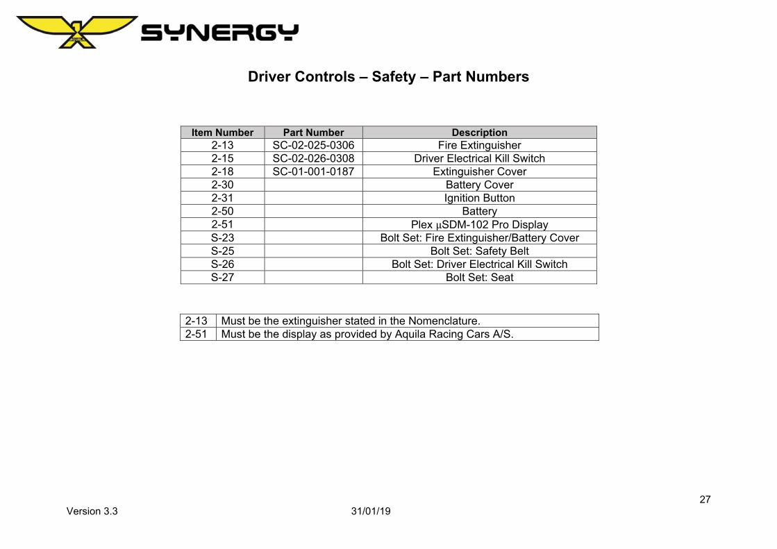
Driver Controls – Safety – Part Numbers
Item Number Part Number Description 2-13 SC-02-025-0306 Fire Extinguisher 2-15 SC-02-026-0308 Driver Electrical Kill Switch 2-18 SC-01-001-0187 Extinguisher Cover 2-30 Battery Cover 2-31 Ignition Button 2-50 Battery 2-51 Plex µSDM-102 Pro Display S-23 Bolt Set: Fire Extinguisher/Battery Cover S-25 Bolt Set: Safety Belt S-26 Bolt Set: Driver Electrical Kill Switch S-27 Bolt Set: Seat
2-13 Must be the extinguisher stated in the Nomenclature. 2-51 Must be the display as provided by Aquila Racing Cars A/S.
28 Version 3.3 31/01/19
Driver Controls – Pedal Box
A B C 2-20 X 2-21 X 2-22 X 2-23 X 2-24 X 2-25 X 2-26 X 2-27 X 2-28 X 2-47 X 2-48 X S-28 X S-29 X
Engine must use original OEM parts. Servicing and cleaning is allowed. The installation of the Oil Sump Baffle Plate, Oil Filter Adaptor and Aquila Synergy Throttle Body are the only allowed changes. Engine code must be 1KR-FE.
3-02 Gearbox must use original OEM parts. Servicing and cleaning is allowed.
3-03, 3-04, 3-05 Must use OEM parts, and adhere to the weight restriction as set out on page 7 Paragraph 5.12.
36 Version 3.3 31/01/19
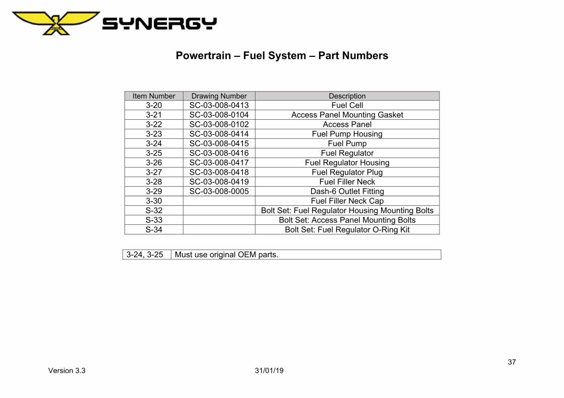
Powertrain – Fuel System
A B C
3-20 X 3-21 X 3-22 X 3-23 X 3-24 X 3-25 X 3-26 X 3-27 X 3-28 X 3-29 X S-32 X S-33 X S-34 X
A B C 5-01 X 5-02 X 5-03 X 5-04 X 5-05 X 5-06 X 5-19 X 5-20 X 5-21 X S-51 X S-52 X S-53 X S-54 X
39 Version 3.3 31/01/19
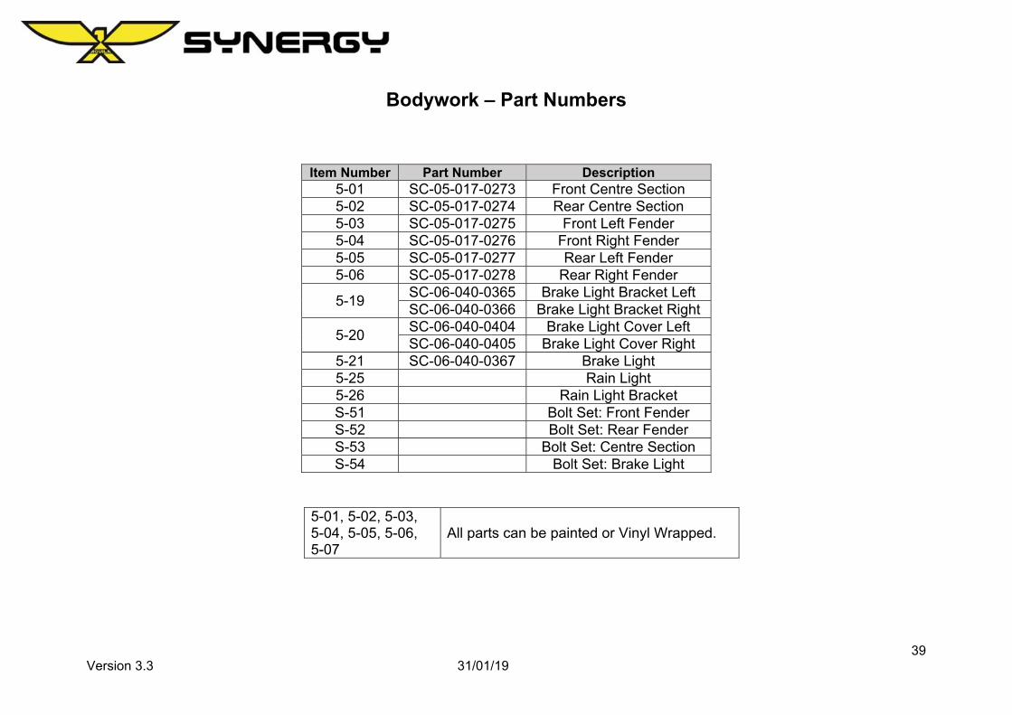
Bodywork – Part Numbers
Item Number Part Number Description 5-01 SC-05-017-0273 Front Centre Section 5-02 SC-05-017-0274 Rear Centre Section 5-03 SC-05-017-0275 Front Left Fender 5-04 SC-05-017-0276 Front Right Fender 5-05 SC-05-017-0277 Rear Left Fender 5-06 SC-05-017-0278 Rear Right Fender
5-19 SC-06-040-0365 Brake Light Bracket Left SC-06-040-0366 Brake Light Bracket Right
5-20 SC-06-040-0404 Brake Light Cover Left SC-06-040-0405 Brake Light Cover Right
A B C 5-07 X 5-08 X 5-09 X 5-10 X 5-18 X 5-22 X 5-23 X S-55 X S-56 X S-57 X S-58 X
S-511 X S-512 X
41 Version 3.3 31/01/19
Bodywork – Floor – Part Numbers
Item Number Part Number Description 5-07 SC-05-055-0407 Diffuser 5-08 SC-05-055-0346 Diffuser Left Strake 5-09 SC-05-055-0345 Diffuser Right Strake 5-10 SC-05-055-0347 Side Mount 5-18 SC-05-054-0408 Front Floor
5-22 SC-05-054-0551 Front Wooden Floor Left Front Wooden Floor Right
5-23 SC-05-054-0552 Rear Wooden Floor Left Rear Wooden Floor Right
S-55 Bolt Set: Mounting Front Floor S-56 Bolt Set: Diffuser to Chassis S-57 Bolt Set: Strakes to Diffuser S-58 Bolt Set: Diffuser to Side Mount
S-511 Bolt Set: Front Wooden Floor to Chassis S-512 Bolt Set: Rear Wooden Floor to Chassis
42 Version 3.3 31/01/19
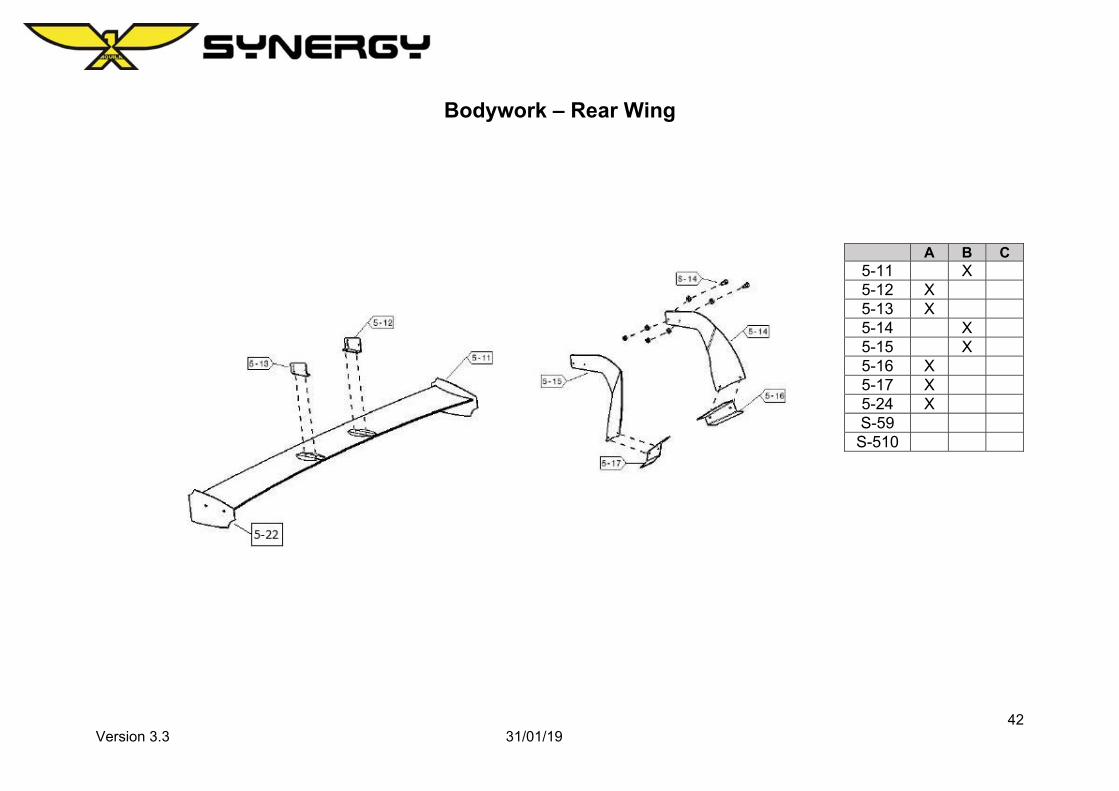
Bodywork – Rear Wing
A B C 5-11 X 5-12 X 5-13 X 5-14 X 5-15 X 5-16 X 5-17 X 5-24 X S-59
S-510
43 Version 3.3 31/01/19
Bodywork – Rear Wing – Part Numbers
Item Number Part Number Description 5-11 SC-05-056-0406 Rear Wing 5-12 SC-05-056-0350 Adjustable Wing Bracket 5-13 SC-05-056-0351 Adjustable Wing Bracket 5-14 SC-05-056-0349 Wing Mount Left 5-15 SC-05-056-0348 Wing Mount Right 5-16 SC-05-056-0354 Wing Mount Bodywork Attachment Plate Left 5-17 SC-05-056-0353 Wing Mount Bodywork Attachment Plate Right 5-22 SC-05-056-0352 Rear Wing End Plate 5-24 Rear Wing Support Brace S-59 Bolt Set: Adjustable Wing Mount to Wing Mount
S-510 Bolt Set: Wing Mount to Bodywork Attachment Plate