32
© 2012 ANSYS, Inc. March 21, 2013 1 Release 14.5 14.5 Release Lecture 01 Introduction to Hydrodynamic Analysis with ANSYS Aqwa

© 2012 ANSYS, Inc. March 21, 2013 1 Release 14.5
14.5 Release
Lecture 01
Introduction to Hydrodynamic Analysis with
ANSYS Aqwa

© 2012 ANSYS, Inc. March 21, 2013 2 Release 14.5
Welcome
Welcome to the ANSYS Hydrodynamic Analysis introductory training course!
This training course covers the basics of using ANSYS Aqwa for performing hydrodynamic analyses.
It is intended for all new or occasional ANSYS Aqwa users, regardless of the CAD software used.
© 2012 ANSYS, Inc. March 21, 2013 3 Release 14.5
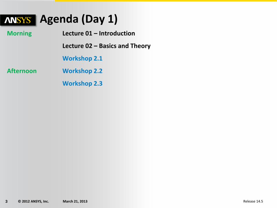
Agenda (Day 1) Morning Lecture 01 – Introduction
Lecture 02 – Basics and Theory
Workshop 2.1
Afternoon Workshop 2.2
Workshop 2.3

© 2012 ANSYS, Inc. March 21, 2013 4 Release 14.5
Agenda (Day 2) Morning Lecture 03 – Aqwa suite (Aqwa-Line)
Workshop 3.1
Lecture 03 – Aqwa suite (Aqwa-Librium)
Workshop 3.2
Lecture 03 – Aqwa suite (Aqwa-Fer)
Workshop 3.3
Afternoon Lecture 03 – Aqwa suite (Aqwa-Drift)
Workshop 3.4
Lecture 03 – Aqwa suite (Aqwa-Naut)
Workshop 3.5

© 2012 ANSYS, Inc. March 21, 2013 5 Release 14.5
Agenda (Day 3) Morning Lecture 04 – Articulations and Multibody
Workshop 4.1
Lecture 05 – Articulations and Multibody (continued)
Workshop 4.2
Afternoon Lecture 05 – Load Mapping
Workshop 5.0

© 2012 ANSYS, Inc. March 21, 2013 6 Release 14.5
Lecture 1: Contents
A. About ANSYS Inc.
B. ANSYS EKM
C. ANSYS Customer Portal
D. ANSYS Workbench Overview
E. ANSYS Mechanical Overview
F. Starting Mechanical
G. Working With Units
H. License Preferences

© 2012 ANSYS, Inc. March 21, 2013 7 Release 14.5
More than 60 offices worldwide plus an extensive network of distributors
Over 2,200 direct employees of ANSYS and its subsidiaries worldwide
Listed on NASDAQ (ANSS)
Visit www.ansys.com for more information
A. About ANSYS, Inc.
Corporate Headquarters Canonsburg, PA

© 2012 ANSYS, Inc. March 21, 2013 8 Release 14.5
A. Breadth of Technologies
Structural Mechanics: From Linear Statics
Fluid Mechanics: From Single-Phase Flows
Electromagnetics: From Low-Frequency Windings
Systems: From Data Sharing
To High-Speed Impact
To Multiphase Combustion
To High-Frequency Field Analysis
To Multi-Domain System Analysis
© 2012 ANSYS, Inc. March 21, 2013 9 Release 14.5
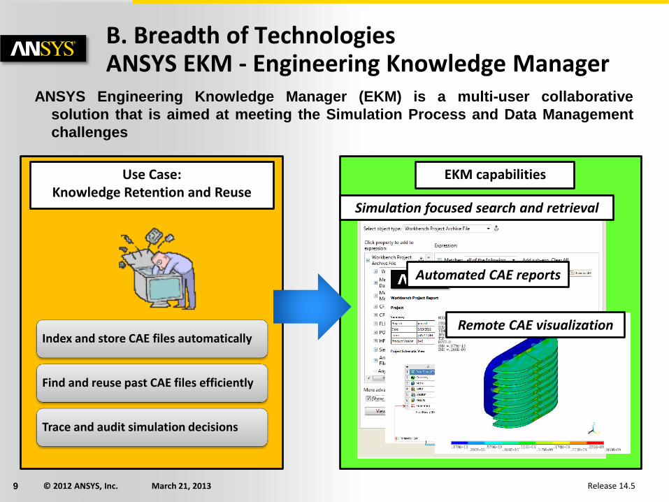
Index and store CAE files automatically
Find and reuse past CAE files efficiently
Trace and audit simulation decisions
B. Breadth of Technologies ANSYS EKM - Engineering Knowledge Manager ANSYS Engineering Knowledge Manager (EKM) is a multi-user collaborative
solution that is aimed at meeting the Simulation Process and Data Management
challenges
Use Case:
Knowledge Retention and Reuse Simulation focused search and retrieval
Automated CAE reports
Remote CAE visualization
EKM capabilities

© 2012 ANSYS, Inc. March 21, 2013 10 Release 14.5
Build and run CAE workflows
Allow multi site, multi user access
Deploy templates for what if studies
. . . Breadth of Technologies ANSYS EKM - Engineering Knowledge Manager
Use Case: Collaboration
Workflow Modeling
Process Tracking
Hosted Applications
EKM capabilities
ANSYS Engineering Knowledge Manager (EKM) is a multi-user collaborative
solution that is aimed at meeting the Simulation Process and Data Management
challenges

© 2012 ANSYS, Inc. March 21, 2013 11 Release 14.5
C. The ANSYS Customer Portal
Contains over 50,000 support assets powered by a modern web user interface and powerful search engine.
Support Products Downloads Knowledge Resources
Classroom Training Webinars Service Requests
Product Assets Latest Release Updates Tools Previous Release(s)
Solutions Conference Proceedings Class3 Reports Documentation Training & Tutorials
support.ansys.com

© 2012 ANSYS, Inc. March 21, 2013 12 Release 14.5
. . . About search
The ANSYS Customer Portal’s search is powered by dedicated Google® hardware.
Mesh = Meshed = Meshing Export = Exported = Exporting XXXXX = YYYYY = ZZZZZ
Example: You want a meshing tutorial for ANSYS Meshing and your search has results for other products that are not of interest to you; by selecting the product facet “ANSYS Meshing” you can narrow down your results further.
Search Facets

© 2012 ANSYS, Inc. March 21, 2013 13 Release 14.5
. . . Support / downloads / training
Submit and review service requests
If you cannot find the answer to your question within the ANSYS Customer Portal then you can submit a service request. A member of ANSYS technical support will then get back to you with advice or a solution.
Download the latest software and updates
Download ISO images if you wish to create a DVD which is recommend for installations on multiple computers and allows you to keep an archive of the installation for later re-use.
Individual downloads can also be selected if you have a limited speed internet connection.
Download classroom and video training material
Training and tutorial material are available for both a broad range of ANSYS products and user’s experience. Search the hundreds of courses available and improve your knowledge of ANSYS software.
© 2012 ANSYS, Inc. March 21, 2013 14 Release 14.5
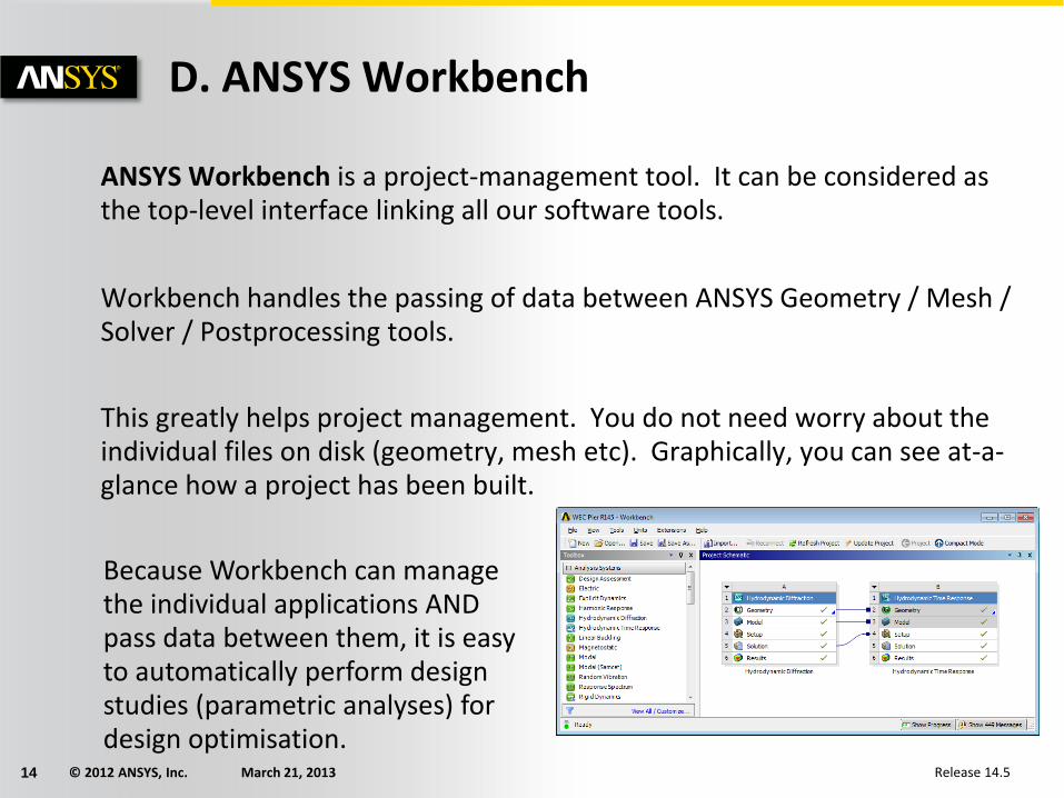
D. ANSYS Workbench
ANSYS Workbench is a project-management tool. It can be considered as the top-level interface linking all our software tools.
Workbench handles the passing of data between ANSYS Geometry / Mesh / Solver / Postprocessing tools.
This greatly helps project management. You do not need worry about the individual files on disk (geometry, mesh etc). Graphically, you can see at-a-glance how a project has been built.
Because Workbench can manage the individual applications AND pass data between them, it is easy to automatically perform design studies (parametric analyses) for design optimisation.

© 2012 ANSYS, Inc. March 21, 2013 15 Release 14.5
. . . Workbench Overview
The options visible in the left-hand column show all the products (systems) you have licenses for.
TIP: If this list appears empty, you have a problem with your licensing!
“Analysis Systems” are ready-made stencils that include all the individual systems (applications) needed for common analyses (for example Geometry + Mesh + Solver + Post-Processor)
“Component Systems” are the individual building-blocks for each stage of the analysis
“Design Exploration” provides tools for optimising designs and understanding the parametric response.

© 2012 ANSYS, Inc. March 21, 2013 16 Release 14.5
. . . Basic Workflow
Dragging an Analysis System onto the project desktop lays out a workflow, comprising all the steps needed for a typical analysis.
Workflow is from top to bottom. As each stage is complete, the icon at the right-hand side changes

© 2012 ANSYS, Inc. March 21, 2013 17 Release 14.5
By dropping applications and/or systems into various locations in the schematic, an overall analysis project is defined.
“Connectors” indicate the level of collaboration between systems.
In the example below a hydrodynamic time response system is dragged and dropped onto a hydrodynamic diffraction system at the Model cell (A3).
Before completing the operation notice there are a number of optional “drop targets” that will provide various types of linkage between systems (continued next page).
. . . Basic Workflow

© 2012 ANSYS, Inc. March 21, 2013 18 Release 14.5
By completing the operation from the previous page, notice the linkage here is only at the Model level and above.
In this case there would be no hydrodynamic database coupling.
Notice too each system block is given an alphabetic designation (A, B, C, etc.).
. . . Basic Workflow

© 2012 ANSYS, Inc. March 21, 2013 19 Release 14.5
By dropping the hydrodynamic time response system at the Solution level we obtain a system that is coupled to the hydrodynamic diffraction solution.
Notice, the candidate
“drop target” indicates
data will be shared
from fields A2 to A3,
and transferred from
A5.
. . . Basic Workflow

© 2012 ANSYS, Inc. March 21, 2013 20 Release 14.5
. . . Alternative Workflow
However, an analysis could equally well be prepared by selecting the individual Component Systems that are needed for this analysis, and then linking them together with connectors. TIP: There are two ways to create the connectors between the systems: 1) Use the mouse to draw a line (eg A2 to B2, B3 to C2 etc) 2) Or, simply drop the new system on the cell of the upstream one,
and the link will be generated automatically.

© 2012 ANSYS, Inc. March 21, 2013 21 Release 14.5
. . . Cell States As each stage in the model-build is completed, the state of the cell changes.
Status after creating Geometry in A2, not yet opened mesh in A3
Status after model has converged, waiting for post-processing
Icon Meaning
Up to Date
Refresh required. Upstream data has changed
Update required. Local data has changed
Unfulfilled. Upstream data does not exist
Attention Required
Solving
Update Failed
Update Interrupted
Changes pending (was up-to-date, but upstream data has changed)

© 2012 ANSYS, Inc. March 21, 2013 22 Release 14.5
. . . Sharing Data between Different Solvers
Workbench can be used to transfer data between solvers. In this 1-way FSI (fluid-structure-interaction) example, we transfer the loads from a Fluent CFD simulation over to a Mechanical system to perform a stress analysis
The square connector shows that the geometry created in cell A2 (CFD model) is being shared with cell B3 (FEA model).
The round connector shows that the CFD results are being transferred as a Setup (input) condition to be used for FEA stress analysis.

© 2012 ANSYS, Inc. March 21, 2013 23 Release 14.5
. . . File Location on Disk
Should you need to identify the individual files on your disk for each stage of the project, these can be found by enabling View > Files. The resulting table will cross-reference the directory and filename with the project cells.
Filename Directory

© 2012 ANSYS, Inc. March 21, 2013 24 Release 14.5
. . . File Management Workbench creates a project file and a series of subdirectories to manage all associated files.
Users should allow Workbench to manage the content of these directories. Please do NOT manually modify the content or structure of the project directories.
When a project is saved a project file is created (.wbpj), using the user specified file name (e.g. Cylinder.wbpj).
A project directory will be created using the project name. In the above example the directory would be Cylinder_files.
A number of subdirectories will be created in the project directory (explained next).

© 2012 ANSYS, Inc. March 21, 2013 25 Release 14.5
. . . Workbench File Management
Directory Structure:
– dpn: this is the design point directory. This essentially is the state of all parameters for a particular analysis. In the case of a single analysis there will be only one “dp0” directory.
– AQW-n: contains subdirectories for each application in the analysis. In the example below the “AQW” directory will contain the database, and other associated files from the Aqwa HD application. “AQW-1” directory will contain the results of the time response analysis. The “Analysis” subdirectory would contain the files associated with that particular solution.
– user_files: contains external user defined files that may be associated with a project. The user is free to use this directory as desired.

© 2012 ANSYS, Inc. March 21, 2013 26 Release 14.5
. . . Use of Archive / Restore
The workbench project comprises many files and directories. If you need to either archive the project, or bundle it to send to us for a Technical Support query, use the ‘Archive’ tool. This generates a single zipfile of the entire project.
When archiving, you can choose whether to include the computed result files or not (omitting these may make it small enough to send by email)

© 2012 ANSYS, Inc. March 21, 2013 27 Release 14.5
. . . Working With Parameters [1]
Most Workbench applications will let you specify key quantities as a parameter (rather than a constant). This will be covered later.
In this CFD example:
• When creating the geometry in DesignModeler, the pipe length is set to be an input parameter.
• When reviewing the results, the pressure drop is set as an output parameter
We could just have easily set up a Mechanical analysis, looking at different loading conditions and reporting the maximum stresses.
© 2012 ANSYS, Inc. March 21, 2013 28 Release 14.5
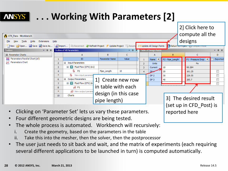
. . . Working With Parameters [2]
• Clicking on ‘Parameter Set’ lets us vary these parameters. • Four different geometric designs are being tested. • The whole process is automated. Workbench will recursively:
i. Create the geometry, based on the parameters in the table ii. Take this into the mesher, then the solver, then the postprocessor
• The user just needs to sit back and wait, and the matrix of experiments (each requiring several different applications to be launched in turn) is computed automatically.
1] Create new row in table with each design (in this case pipe length)
2] Click here to compute all the designs
3] The desired result (set up in CFD_Post) is reported here

© 2012 ANSYS, Inc. March 21, 2013 29 Release 14.5
Summary
ANSYS Workbench is a convenient way of managing your simulation projects.
Workbench is used to launch the individual software components, and used to transfer data between them.
It is easy to see at-a-glace how a model has been built, and determine which files were used for a particular simulation (pairing geometry files to solver runs)
Workbench also makes it straightforward to perform parametric analyses (without the user needing to manually launch each application in turn), and makes it easy to simulate multi-physics scenarios like fluid-structure interaction.

© 2012 ANSYS, Inc. March 21, 2013 30 Release 14.5
C. ANSYS Hydrodynamic Analysis Overview
What is Aqwa?
• Aqwa is a modularised, fully integrated hydrodynamics analysis suite based around 3-D diffraction/radiation methods.
• ANSYS Workbench implementation provides hydrodynamic diffraction and time domain simulations.
History of Aqwa
• Developed since 1971 (by WS Atkins)
• Owned and developed by Century Dynamics since 2001
• Century Dynamics acquired by ANSYS February 2005
• Now being integrated into the ANSYS Workbench system

© 2012 ANSYS, Inc. March 21, 2013 31 Release 14.5
. . . ANSYS Hydrodynamic Analysis Overview
ANSYS Aqwa Capabilities
• Diffraction/Radiation including Morison elements
• Frequency domain analysis
• Stability including mooring lines
• Time domain with irregular waves
• Time domain with non-linear survival waves
• Coupled cable dynamics
• Multiple hydrodynamic interaction and articulations (up to 50 structures)
• Transfer of motions and pressures to ASAS & ANSYS FE models

© 2012 ANSYS, Inc. March 21, 2013 32 Release 14.5
. . . ANSYS Hydrodynamic Analysis Overview
ANSYS Aqwa Applications
• Determination of RAOs
• Wave bending moments
• Splitting Force calculations for Semi-Submersibles
• Design and analysis of mooring systems
• Time history of motions
• Determination of Air Gaps
• Calculation of Shielding Effects of ships and barriers
• Multiple Body Interactions
• Coupled mooring line-structure interaction
• Cable Dynamics with intermediate buoys
• TLP tether analysis


