Page 1
© 2015 Eaton. All Rights Reserved..
Arc Flash Standards and Arc Flash Risk Reduction Technologies
Solutions that reduce arc flash injuries and equipment damage
Bob Yanniello
VP of Engineering
Electrical Systems & Services
Eaton
Page 2
2© 2015 Eaton. All Rights Reserved..
Arc flash safety
• On average, only 1 out of every 240 workplace
accidents involve electricity (0.4%)
• However, 1 out of every 24 work related
deaths involve electricity (4%)
This underlines the need for strong
emphasis on Electrical Safety
Page 3
3© 2015 Eaton. All Rights Reserved..
Arc flash safety
Page 4
4© 2015 Eaton. All Rights Reserved..
Why is an arc a hazard?
Pressure Waves
Copper Vapor:Solid to VaporExpands by
67,000 times
Molten Metal
Intense Light
Hot Air-Rapid Expansion
35,000 °F
Shrapnel
Sound Waves
Pressure Waves
Copper Vapor:Solid to VaporExpands by
67,000 times
Copper Vapor:Solid to VaporExpands by
67,000 times
Molten Metal
Intense Light
Hot Air-Rapid Expansion
35,000 °F
Shrapnel
Sound Waves
Page 5
5© 2015 Eaton. All Rights Reserved..
Unfortunately – bad things can and do
happen
Page 6
6© 2015 Eaton. All Rights Reserved..
Unfortunately – bad things can and do
happen
Page 7
7© 2015 Eaton. All Rights Reserved..
Unfortunately – bad things can and do
happen
Page 8
8© 2015 Eaton. All Rights Reserved..
Potential causes of arc flash events
• Poorly maintained equipment
• Poor operating environments
• Conductive objects left in equipment
• Dropping conductive objects into equipment
• Insulation breakdown (MV typically)
• Animal ingress
Page 9
© 2015 Eaton. All Rights Reserved..
Codes and StandardsRelated to Arc Flash Safety
Page 10
10© 2015 Eaton. All Rights Reserved..
New OSHA electrical safety final rule published
• OSHA does not support the NFPA 70E “table methods”
in terms of estimating incident energy
• Additional language recognizes the latest NFPA 70E
consensus standards should be the foundation for safety
standards.
Page 11
11© 2015 Eaton. All Rights Reserved..
Key changes
• The employer must assess the workplace to identify workers exposed to flame or electric-arc hazards.
• No later than January 1, 2015, employers must estimate the incident heat energy of any electric-arc hazard to which a worker would be exposed.
• No later than April 1, 2015, employers generally must provide workers exposed to hazards from electric arcs with protective clothing and other protective equipment with an arc rating greater than or equal to the estimated heat energy.
New OSHA electrical safety final rule published
Page 12
12© 2015 Eaton. All Rights Reserved..
NFPA 70E – Standard for Electrical Safety In The Workplace – key 2015 changes
• Amended the definition of a “qualified
person”
• One who has demonstrated the skills and
knowledge related to the construction and
operation of electrical equipment and
installations and has received safety
training to identify and avoid the hazards
involved.
Page 13
13© 2015 Eaton. All Rights Reserved..
NFPA 70E – Standard for Electrical Safety In The Workplace – key 2015 changes
• Changed term to “Arc Flash Risk
Assessment” rather than “Arc Flash
Hazard Analysis”
• Separating terms “Risk” and “Hazard”
• Risk Assessment includes not only the
severity, but also the likelihood
• No more “Hazard Risk Categories” –
Replaced with “Arc Flash PPE
Category”
Page 14
14© 2015 Eaton. All Rights Reserved..
NFPA 70E – Standard for Electrical Safety
In The Workplace – key 2015 changes
• Provides tables for required PPE level – Now
based on Equipment type rather than task
• Separate tables for AC and DC
Page 15
15© 2015 Eaton. All Rights Reserved..
NFPA 70E – Standard for Electrical Safety In The Workplace – key 2015 changes
• Removed Hazard Risk (PPE) Category 0
• Added PPE Tables:
Page 16
16© 2015 Eaton. All Rights Reserved..
NFPA 70E – Standard for Electrical Safety In The Workplace – key 2015 changes
• Emphasis on proper maintenance per manufacturer’s recommendations and installation per NEC and industry standards
• Defines “normal operation” under energized work as performed on equipment that:
• Is properly installed
• Is properly maintained
• Has doors closed and secured
• Has all covers in place and secured
• Has no evidence of impending failure
Page 17
17© 2015 Eaton. All Rights Reserved..
NFPA 70E – Standard for Electrical Safety In The Workplace – key 2015 changes
• Equipment Labeling
• “Electrical equipment such as switchboards,
panelboards, industrial control panels, meter socket
enclosures, and motor control centers that are in other
than dwelling units and that are likely to require
examination, adjustment, servicing, or maintenance while
energized shall be field-marked”
• Label must include: (red text in 2012 version)
1. Nominal system voltage
2. Arc Flash boundary
3. One of the following:
1) Either the arc flash PPE category from the tables OR available incident energy and corresponding working distance, but not both on the same piece of equipment.
2) Minimum arc rating of clothing
3) Site specific level of PPE
Page 18
18© 2015 Eaton. All Rights Reserved..
NFPA 70E – Standard for Electrical Safety In The Workplace
• Requires safety “re-training” at
intervals of not more than 3 years
(not new – added in 2012)
• The arc flash risk assessment
must be updated after any major
renovation or at a intervals not to
exceed 5 years.
(not new – added in 2009)
Page 19
19© 2015 Eaton. All Rights Reserved..
1. Power (intensity) of the arc at its origin
2. Distance of the worker from the arc origin
3. Time duration of the arc exposure
Arc flash hazard evaluation
Skin damage will occur based on the intensity of
the heat generated by an electrical arc accident.
The heat reaching the skin of the worker is
dependent on the following three factors:
1.2 cal/cm2 exposure limits skin burn to 2nd degree (skin will regenerate)
Page 20
20© 2015 Eaton. All Rights Reserved..
Need a total system approach to most effectively reduce arc flash risk
• Label Equipment
• Train Personnel On Proper Safety Practices
• Reduce available fault current
• Redirect blast energy
• Faster clearing time
• Move people farther away
• Minimize the probability of faults occurring
De-Energize and lockout the circuits prior
to working on equipment!
Presentation
Outline
Page 21
© 2015 Eaton. All Rights Reserved..
Label Equipment
Page 22
22© 2015 Eaton. All Rights Reserved..
Proper labeling is imperative to make sure you get your message across…..
Page 23
23© 2015 Eaton. All Rights Reserved..
Get it?
Page 24
24© 2015 Eaton. All Rights Reserved..
It is very important that you understand how to interpret labeling
Page 25
25© 2015 Eaton. All Rights Reserved..
It is very important that you understand how to interpret labeling
Page 26
26© 2015 Eaton. All Rights Reserved..
Sample Arc Flash Labels
• Information is not intuitive!
• Without proper training, crucial safety information
on the labels will be ignored
Page 27
© 2015 Eaton. All Rights Reserved..
Train Personnel On Proper Safety Practices
Page 28
© 2015 Eaton. All Rights Reserved..
The Top 6 Safest Practices…
Page 29
29© 2015 Eaton. All Rights Reserved..
Number 6…
Taking safety to
new heights…
Page 30
30© 2015 Eaton. All Rights Reserved..
Number 5…
Yankee
ingenuity…
Page 31
31© 2015 Eaton. All Rights Reserved..
Number 4…
From the
Stevie
Wonder
School of
fork lift
operation
Page 32
32© 2015 Eaton. All Rights Reserved..
Number 3…
PPE = Pink
Personal
Equipment
Page 33
33© 2015 Eaton. All Rights Reserved..
Number 2…
It’s only
low-voltage…
Page 34
34© 2015 Eaton. All Rights Reserved..
Number 1…
The
Darwin/MacGyver
Award goes to
these guys
Page 35
35© 2015 Eaton. All Rights Reserved..
Better– All of Body Protected
Train personnel to use “good” safety practices
Bad – Exposed Back of Neck, Head and Hair
Balaclava
Best
Page 36
36© 2015 Eaton. All Rights Reserved..
Train personnel to use “good” safety practices
Potentially
exposed
ankles
Page 37
© 2015 Eaton. All Rights Reserved..
Reduce Available Fault Current(Reduce Incident Energy)
Page 38
38© 2015 Eaton. All Rights Reserved..
Reduce the available fault current through added impedance
• Use small kVA isolation
transformers / current
limiting reactors
• NOTE: Lowering short circuit
current does not always lower
incident energy
• There is no single answer
• Must conduct an arc flash study
• Must have accurate information
• Estimates/assumptions can
dramatically change the results
Page 39
39© 2015 Eaton. All Rights Reserved..
Reduce the available fault current through current limiting
• Active devices that force
current through a current
limiting element when
fault current exceeds a
predetermined value
Normal current path
High fault current path
Page 40
40© 2015 Eaton. All Rights Reserved..
Combination circuit breakers
• Power circuit breakers with integral current limiters provide the best of both worlds.
• Current limitation under high fault conditions
• Fast opening for lower level faults
• Self-powered overload protection
• Trip units with communications, metering, ZSI, GF protection, etc
• Remote control capability
Page 41
© 2015 Eaton. All Rights Reserved..
Redirect Fault Energy –ANSI / IEEE Arc Resistant Switchgear
Page 42
42© 2015 Eaton. All Rights Reserved..
Arc flash protection guidelines and standards update
• ANSI / IEEE C37.20.7
• IEEE Guide for Testing Metal-Enclosed Switchgear
Rated Up to 38 kV for Internal Arcing Faults
• 2007 Latest Edition
• Gives testing guidelines for confirming arc
resistant capability of metal-enclosed
switchgear
• Manufacturer’s are given significant latitude in how
their assemblies can be tested
• New guide in development will address LV
MCC, MV MCC, switchboards, non seg bus
and possibly gas insulated switchgear
Not all Arc Resistant assemblies are created equally.
It is important to understand the specific ratings and
capabilities. Do not just rely on statements such as
“Tested per ANSI/IEEE C37.20.7”.
Page 43
43© 2015 Eaton. All Rights Reserved..Shuster
Typical arc resistant switchgear test configuration
Test is successful if:
• No indicators burn
• Doors do not open
• No projectiles >60 g
come from equipment
lower than 2 meters
• No holes are burned in
the enclosure at a
height lower than 2
meters
• All grounds remain
intact
PlenumExhaust
Duct
Page 44
44© 2015 Eaton. All Rights Reserved..
Arc Resistant Switchgear – Arc Test Duration
• IEEE C37.20.7, section 4.3 gives a “preferred” arcing duration
rating of 0.5s, but allows a rating as low as 0.1s depending on the
speed of the main protective device used in the testing.
• Duration Rated vs. Device Limited
• C37.20.7 allows the use of protective devices, relays, schemes, ZSI,
and other fast acting mechanisms to limit the arcing energy by
shortening the duration of the event.
• The equipment nameplate is required to indicate if the arc rating is based
upon active devices/systems.
Important to understand what “active” elements are required to function for the
operator to have the expected level of safety protection.
Page 45
45© 2015 Eaton. All Rights Reserved..
Arc resistant switchgear – arc initiation location
• IEEE C37.20.7, requires that the arc be initiated in the “most likely location” of an arcing event.
• In compartmentalized switchgear assemblies, where is the most likely location of an arcing fault?
• Cable compartment?
• Main Bus Compartment?
• Breaker Compartment?
• Location of the arc has a TREMENDOUS affect on the enclosure’s ability to contain the arc energy and/or channel it away from an operator.
• The location of the arc initiation point impacts:• Steel thickness
• Door latch requirements
• Pressure relief systems and locations
• Arc blast exhaust path
• Component location and configuration• Changes in component layout inside the assembly can affect the ability of the enclosure to contain the
arc blast.
Page 46
46© 2015 Eaton. All Rights Reserved..
Arc resistant switchgear –application & installation considerations
� What is the kA & time rating required for the equipment?
� Is direct venting with arc exhaust duct possible?
� If arc exhaust duct is required, how many? Has a safe exhaust location been determined? Has the duct layout been established? Is any duct required to be outdoor with a NEMA 3R rating?
� In what environment will the switchgear be placed? (ie. switchgear room, IPA, C1D2 area, basement?) Is a firewall required at exhaust penetration?
� Is close coupling to other equipment (ie. switches, transformers, motor starters) required? If so, are common plenums available? Multiple ducts?
Modification of the enclosure is not allowed, as it may void arc resistant rating!
Page 47
47© 2015 Eaton. All Rights Reserved..
EEMAC G14-1 (Canada)
• Type A - Arc resistant at front only
• Type B - Arc resistant around the perimeter of the switchgear line-up
• Type C - Arc resistant to Type B plus between all adjacent compartments.
IEC 62271-200 (Rest of World)
• Type A - Arc resistant for restricted areas. IE. Authorized personnel ONLY
• Type B - Arc resistant for unrestricted areas. IE. General public access.
• Type C - Pole Mounted Equipment
• (accessibility types: F-front side, L-lateral side & R- rear side)
IEEE C37.20.7 (USA)
• Type 1 - Arc resistant at front only
• Type 2 - Arc resistant around the perimeter of the switchgear line-up
Appendix A
• Suffix B - Arc resistant to Type 1 or 2 with control door open.
• Suffix C - Arc resistant to Type 1or 2 plus between adjacent compartments.
• Suffix D - specifies Type 1 and applicable accessible sides
Arc resistant switchgear – protection types
Page 48
48© 2015 Eaton. All Rights Reserved..
Arc resistant switchgear – key take away
• The most rigorous arc resistant switchgear testing plan
includes initiating arcs in all compartments (breaker, bus, &
cable) for a full 0.5s, to guarantee the safest arc resistant
switchgear.
Some manufacturer’s do not publish detailed arcing duration or arc initiation
information on their products which claim to be Arc Resistant “per ANSI C37.20.7”
Page 49
49© 2015 Eaton. All Rights Reserved..
Canadian arc resistant protection guideline
• CSA C22.2 No. 0.22-11 published in August 2011
• Draws on a number of standards addressing arc resistance of enclosed electrical equipment
• Scope of coverage is indoor and outdoor equipment up rated up to 46 kVac that uses air as the primary insulating medium
• Testing and evaluation criteria based primarily on IEEE C37.20.7
• Much of the text reads the same
• Assessment criteria is identical
Page 50
50© 2015 Eaton. All Rights Reserved..
Arc resistant metal-clad switchgear features
• Heavier gauge reinforced
doors and covers
• Closed Door Breaker
Operation
• Breaker Racking
• Manual Open
• Viewing of Breaker Status
& Position
Page 51
51© 2015 Eaton. All Rights Reserved..
Arc resistant metal-clad switchgear
Page 52
52© 2015 Eaton. All Rights Reserved..
Draw-Out Auxiliary Drawers
Auxiliary Racking
Mechanism is
accessible
through the door
All auxiliary drawers are equipped
with levering mechanism
Page 53
53© 2015 Eaton. All Rights Reserved..
Sealed relay compartment on
the front of the breaker door
is hinged for easy access.
Arc resistant switchgear – Type 2BRelays and controls can be mounted on the breaker door
Breaker access door is
interlocked such that door can
not be opened until breaker is
in disconnected position
Page 54
54© 2015 Eaton. All Rights Reserved..
Typical arc resistant switchgear assembly
Rugged Construction
• Formed steel compartment design
provides sealed joints under fault
conditions.
• Roof mounted pressure release
flaps allow for the release of arc
exhaust
• Arc pressure exits through top of
each individual vertical section
Pressure
Release Flaps
Page 55
55© 2015 Eaton. All Rights Reserved..
Dynamic flap system
• Ventilation openings must seal under arc condition, but must
remains open during normal operation for proper ventilation of
equipment. Dynamic Flaps utilize gravity to hold open, and will
quickly close under the pressure of an arcing event.
Page 56
56© 2015 Eaton. All Rights Reserved..
Arc resistant LV switchgear – design features
Key Features:
�Through-the-door breaker design
�Arc resistance on all 4 sides (Type 2)
�Secondary terminations and control compartment access (Type 2B)
�Stronger breaker door & latch mechanism
�4-high breaker design
Page 57
57© 2015 Eaton. All Rights Reserved..
LV MCC arc resistant features
• Device limited (vs. duration limited) ratings are common for this class of equipment
• Arc Prevention Features
• Insulated horizontal bus and vertical bus
• Automatic bucket shutters
• Isolation barriers installed between each structure
• Serves to help isolate and contain the arc flash event within a single structure
Isolation
Barriers
Insulated
Bus
Page 58
58© 2015 Eaton. All Rights Reserved..
• Infrared (IR) Scanning Windows
• On arc resistant equipment, make sure brand was arc tested on the specific equipment and in specific mounting location.
Shield the operator with closed doors/panels
Page 59
© 2015 Eaton. All Rights Reserved..
Faster Clearing Time
Page 60
60© 2015 Eaton. All Rights Reserved..
2014 NEC – key change to reduce arc flash risk
240.87 Arc Energy Reduction
ALL circuit breakers greater than or equal to 1200 A will now require:
“A Method to Reduce Clearing Time. One of the following or approved equivalent means
shall be provided:
(1) Zone-selective interlocking or
(2) Differential relaying or
(3) Energy-reducing maintenance switching with local status indicator or
(4) Energy-reducing active arc flash mitigation system or
(5) An approved equivalent means”
“Energy-reducing maintenance switching” methods are the most
economical solution, but all solutions are not created equally…
Doesn’t quantify any required level of reduction.
Page 61
61© 2015 Eaton. All Rights Reserved..
SD = 0.5 s
SD=
0.3 s
SD=
0.3 s
SD=
0.3 s
M1
F1 F2 F3
With ZSI = 0.08 sec
35 kA fault, 7.0 Cal/cm2
Cat. 2 PPE
X
XFault Location #2
Fault Location #1
NOTE: There is some time delay with ZSI to allow the upstream device to
wait for a restraint signal from a downstream device.
Restraint Signal
Without ZSI = 0.5 sec
35 kA fault, 43.7 Cal/cm2
Greater than Cat. 4 PPE!
Zone Selective Interlocking example
Page 62
62© 2015 Eaton. All Rights Reserved..
Arc Flash Reduction Maintenance System (ARMS)
Status indicator
Local on/off switch
Current threshold
setting to avoid
pick-up for high
load levels and
inrush
Page 63
63© 2015 Eaton. All Rights Reserved..
Arcflash Reduction Maintenance System (ARMS)
• When activated, total breaker clearing time is reduced to 40 msec!
• One manufacturer’s ARMS protection is “faster than instantaneous”
• Bypasses all microprocessor delays
• Normal settings – 10.7 cal/cm2
• With ARMS enabled – 2.2 cal/cm2
0. 5 1
1
10
10
100
100
1K
1K
10K
10K
0. 01 0. 01
0. 10 0. 10
1 1
10 10
100 100
1000 1000
CURRENT I N AMPERES
TI
ME
IN SE
CONDS
480V FEEDER CUTLER-HAMMER ARMS Trip 1600.0 APlug 1600.0 ASettings ARMS ARMS R5 (4000A)
480V FEEDER CUTLER-HAMMER Magnum DS, RMS 520 Trip 1600.0 APlug 1600.0 ASettings Phase LTPU (0.4-1.0 x P) 1 (1600A) LTD (2-24 Sec.) 12 STPU (2-12 x LTPU) 6 (9600A) STD (0.1-0.5 Sec.) 0.2 (I 2t In) INST (2-12 x P) M1(12) (19200A)
Motor 700.0 hp
Some manufacturer’s “maintenance
modes” are slower than normal
instantaneous tripping (ZSI based)
providing limited or no arc flash
energy reduction.
Page 64
64© 2015 Eaton. All Rights Reserved..
ARMS – features
• Independent from standard overcurrent settings (doesn’t require changing the programmed settings)
• Trip times equal to or shorter than instantaneous tripping
• Adjustable to allow maximum reduction without nuisance tripping
• Can be activated:
1. Locally
2. Remote selector switch (or dry contact)
3. Over communications network
• Local status indication (required by code) and at downstream protected equipment
• Must be able to be integrated into normal lockout –tag-out procedures
Page 65
65© 2015 Eaton. All Rights Reserved..
Actual arc flash incident protected by ARMS
Page 66
66© 2015 Eaton. All Rights Reserved..
ARMS capability of 1200 A over current protective devices (OCPDs) (9kA @ 480V)
Breaker w/ Maintenance ModeBreaker w/ Instantaneous1200 A Fuse
(Click videos to view)
Page 67
67© 2015 Eaton. All Rights Reserved..
Device Fuse
L-Class
N-frame w/
Instantaneous
N-frame w/
Maint. Mode
Peak Fault Current (kA)
Time to Clear (ms)
Arcflash Energy (Cal/cm2)
Hazard Risk Category (NFPA 70E 2012)
15.7 14.8 14.5
771.0 45.9 18.2
17.89 1.63 0.41
OCPD 1200 A comparison table(9 kA @ 480 V)
94% 98%
---- 60%
----
----
[improvement vs. Fuse]
[improvement vs. Instantaneous]
91% 98%
---- 75%
----
----
[improvement vs. Fuse]
[improvement vs. Instantaneous]
3 1 0
8.0 – 25.0 Cal/cm2 1.2 – 4.0 Cal/cm2 0.0 – 1.2 Cal/cm2[Incident Energy Range]
Page 68
68© 2015 Eaton. All Rights Reserved..
Substation protection – fused transformer
• Secondary of substation
transformers are typically high
arc flash risk zones (with or
without a secondary main)
• Trip times are long because
arc faults have to reflect
through the transformer
• Primary fuses react very slowly
to secondary arcing and
ground faults
Page 69
69© 2015 Eaton. All Rights Reserved..
Substation protection - fused transformer
• 1500 kVA xfmr, Z = 5.75%
• Bolted fault current = 28.84 kA
• Arcing fault current = 16.20 kA
Arcing current reflected through
transformer would take in excess of 6
seconds to clear primary fuse!
Page 70
70© 2015 Eaton. All Rights Reserved..
Substation protection - fused transformer
Bus Name Protective Bus Bus Prot Dev Prot Dev Trip/ Breaker Arc Working Incident PPE Level / Notes (*N)
Device kV Bolted Bolted Arcing Delay Opening Flash Distance Energy
Name Fault Fault Fault Time Time/Tol Boundary (in) (cal/cm2)
(kA) (kA) (kA) (sec.) (sec.) (in)
XFMR SEC PRI FUSE 0.48 28.84 28.84 16.20 2 0.000 286 18 112 Dangerous!
SEC SWGR (SEC MAIN LineSide)
PRI FUSE 0.48 28.59 28.59 16.09 2 0.000 285 18 111 Dangerous!
MCC SWGR FEEDER
0.48 25.30 25.30 14.49 0.065 0.000 33 18 3.2 Level 1
• Anywhere from the xfmr secondary to the
line side of the secondary main breaker is
arc flash PPE category DANGEROUS
• If line side of secondary main breaker is not
isolated with barriers to prevent propagation
to load side, this level applies to the entire
secondary switchgear.
Page 71
71© 2015 Eaton. All Rights Reserved..
Transformer with integral vacuum interrupters (VIs) on primary
• Under oil vacuum interrupter integral
to transformer tank
• 750-10,000 kVA
• Primary: Thru 34500GY/19920 V
150 kV BIL
• 600 A Cont.
• 16,000 A rms interrupting
• Self-powered relay for primary
protection
• Saves footprint and $$$ by
eliminating separate primary switch
or breaker
Page 72
72© 2015 Eaton. All Rights Reserved..
VIs with series visible break
• Optional Visible break available to still allow visible inspection of blade position
• Large, easily viewed knife blades through window
• Closed, open or grounded contact position
• Placed in series with VI mechanism
• Mechanically interlocked to ensure load-break and load-make operations occur in the vacuum interrupters
Page 73
73© 2015 Eaton. All Rights Reserved..
Substation protection – transformer with integral vacuum interrupters (VIs)
• Replace transformer fuse
protection with integral VIs
• Self-powered, adjustable
primary protection
• CT’s on secondary bushings
or spades
• Simple 50/51, 50G/51G
overcurrent relay protection
on secondary cts
• Ability to trip primary VIs
from secondary relay
Page 74
74© 2015 Eaton. All Rights Reserved..
Substation protection – transformer with integral vacuum interrupters (VIs)
• 1500 kVA xfmr, Z = 5.75%
• Bolted fault current = 28.84 kA
• Arcing fault current = 16.20 kA
Total clearing time of only 0.100 sec – 0.05 sec for relay operation + 0.05 sec for VI operation (100 msec)!
Completely adjustable protection to allow customization of arc flash reduction versus selective coordination.
• Shown with INST off and delay of 0.05 sec
Page 75
75© 2015 Eaton. All Rights Reserved..
Substation protection – transformer with integral vacuum interrupters (VIs)
• Anywhere from xfmr secondary to the load side of the secondary main breaker incident energy is reduced to 5.6 cal/cm2 (Category 2)
• Protection applies to entire secondary switchgear
• Increasing secondary relay / main breaker Short Time Delay to 0.3 seconds for better selective coordination only increases incident energy to 11.5 cal/cm2 (Category 3)
Bus Name Protective Bus Bus Prot Dev Prot Dev Trip/ Breaker Arc Working Incident PPE Level / Notes (*N)
Device kV Bolted Bolted Arcing Delay Opening Flash Distance Energy
Name Fault Fault Fault Time Time/Tol Boundary (in) (cal/cm2)
(kA) (kA) (kA) (sec.) (sec.) (in)
XFMR SEC SEC RELAY 0.48 28.84 28.84 16.20 0.05 0.050 46 18 5.6 Level 2
SEC SWGR SEC RELAY 0.48 28.59 28.59 16.09 0.05 0.050 46 18 5.5 Level 2
MCC SWGR FEEDER 0.48 25.30 25.30 14.49 0.065 0.000 33 18 3.2 Level 1
Page 76
76© 2015 Eaton. All Rights Reserved..
Substation protection – transformer with integral vacuum interrupters (VIs)
Liquid Xfmr Advantages:• Better Efficiency / Less Losses• Greater Overload Capacity• Deadfront Construction• Extended Life• Integral Primary Protection• Less Floor Space Required
Page 77
77© 2015 Eaton. All Rights Reserved..
Substation protection – with various vacuum interrupting devices
• Any vacuum switching option on the primary that meets the system short circuit capability can allow significant arc flash energy reduction
• Traditional metal-clad switchgear with vacuum circuit breakers
• Metal-enclosed vacuum breakers
• Padmounted switchgear with VI’s
• Vacuum reclosers
• Any type of relay protection can be utilized on the secondary
• Simple 50/51
• Multifunction protective relay
Transformers with integral VIs and simple 50/51 relay are the most cost effective option available.
Actually saves $$$ over “traditional” switch and fuse primary and increases protection!
Page 78
78© 2015 Eaton. All Rights Reserved..
Existing Substation Retrofit Example
• Many existing fused substations with significant arc flash risk problems
• Retrofit with vacuum circuit breaker with Arcflash Reduction Maintenance System (ARMS)
• Utilizes same ARMS protection available on LV power circuit breakers
• Ideal for retrofit applications replacing existing fused primary switches due to compact size and capabilities
Page 79
79© 2015 Eaton. All Rights Reserved..
Arcflash Reduction Maintenance System (ARMS)
• When activated, breaker total clearing time is reduced to 40 msec!
• Typical MV Breakers are 50 msec plus relay detection time!
• “Faster than Instantaneous”
• Bypasses all microprocessor delays
• Medium-voltage vacuum circuit breaker with integral self-powered relay
• ZSI capability primary-to-secondary
Page 80
80© 2015 Eaton. All Rights Reserved..
Before After
Existing Substation Retrofit Example
Page 81
81© 2015 Eaton. All Rights Reserved..
Practical Methods for Reducing Arc Flash
HazardsMultiple Settings Groups
• Similar to LV maintenance switch, only for MV applications
• Used to reduce the trip delay of medium-voltage relays while maintenance (ex. Racking, opening, closing of breakers or auxiliary drawers) is being performed on equipment.
• Most modern microprocessor based relays have multiple settings groups, such as the Eaton E-Series Relays
Page 82
82© 2015 Eaton. All Rights Reserved..
ARMS using multifunction protective relay – multiple group settings
Switch
Indicating Light
Relay with
multiple setting
groups
Page 83
83© 2015 Eaton. All Rights Reserved..
Arc Flash Light Sensing Relay Protection
• Relays with arc-flash light
sensors and ct input can be
utilized to reduce tripping
times
• These can help reduce
equipment damage
• These systems do not provide
the functionality of arc
resistant switchgear for
personnel safety
Arc
Flash
Relay
Page 84
84© 2015 Eaton. All Rights Reserved..
Anatomy of an internal arcing fault – four stages
• Most damage
occurs within
the first cycle
• Within 10 msecpressure can reach more than 4200 lbs/ft2
• Pressure wave peak occurs in first ½ cycle
• Multi-cycle protective devices only reduce thermal duration of the event
3 Cycles 5 Cycles
Page 85
85© 2015 Eaton. All Rights Reserved..
Bus VTs
Line VTs
Typical Sectional View
Breaker in lower and vts in upper compartment
Front
Arc Flash Light Sensing Relay Protection –Point Sensor Locations / Routing
• Installed system must be tested to assure:
• No “blind spots”
• No nuisance operation from “good arcs” from protective devices – LV in particular
• Retrofits on untested systems provide a false sense of security
• Sensors utilizing glass fiber optic cables are fragile
• Extreme care needs to be taken to avoid breakage
• Fibers can be difficult to terminate across shipping splits.
Point
sensors
Page 86
86© 2015 Eaton. All Rights Reserved..
Arc extinction technologies
• High current and the flash of light from the internal fault trigger the extinction device and trips the upstream breaker.
• This technology applies a bolted short across the buses to collapse the voltage and extinguish the arc.
• These devices haves been a commercially available for LV systems in Europe since 1994.
• Not popular in the US. Users in the US have concerns about the stresses placed on cables, terminations, and equipment during bolted fault conditions.
Page 87
© 2015 Eaton. All Rights Reserved..
Move People Farther Away
Page 88
88© 2015 Eaton. All Rights Reserved..
Remote racking systems – why?...
Page 89
89© 2015 Eaton. All Rights Reserved..
Universal remote power racking devices
• LV or MV
• Any breaker – multiple
manufacturers
• 2 high MV
• 4 high LV
• Intelligent
programmable
controllers
• Torque limited
• Can count # of
turns
Page 90
90© 2015 Eaton. All Rights Reserved..
Portable product specific remote electrically operated racking devices
Page 91
91© 2015 Eaton. All Rights Reserved..
Integral motorized racking options for circuit breakers and auxiliary drawers
Personnel safety:
• Allows operator to remain outside
the arc-flash zone while racking
• LEDs on pendant indicate
positions within the cell
• For new equipment as well as
retro-fits
• HMI operation options
Pendant
Page 92
92© 2015 Eaton. All Rights Reserved..
ELECTROSWITCHChicken Switch
Breaker control switch solutions
Page 93
93© 2015 Eaton. All Rights Reserved..
Draw-out molded case circuit breaker forpanelboards & switchboards
Page 94
94© 2015 Eaton. All Rights Reserved..
Deadfront
cover
Removal
handles
Breaker
visibility
Racking
window
Draw-out molded case circuit breaker with IR window option
Page 95
95© 2015 Eaton. All Rights Reserved..
MCC buckets with integral levering capability
Bucket Position
�Connected
�Test
�Withdrawn
Handle Mechanism
Device Island
• Start, Stop, Auto, Man
Unit Latch
Breaker
Internal Shutter Position
�Open
�Closed
Racking Tool Receiver
Starter
Page 96
© 2015 Eaton. All Rights Reserved..
Minimize The Probability of Faults Occurring
(These techniques do NOT necessarily reduce incident energy or required PPE)
Page 97
97© 2015 Eaton. All Rights Reserved..
480 volt MCC insulation/isolation options
97
Automatic
Shutters
Isolation
Barriers
Insulated
Bus
Page 98
98© 2015 Eaton. All Rights Reserved..
LV switchgear isolation options
Optional barriersOptional shutters
Page 99
99© 2015 Eaton. All Rights Reserved..
Rodent (?) proofing…
Page 100
100© 2015 Eaton. All Rights Reserved..
LV switchgear insulated bus options
Page 101
101© 2015 Eaton. All Rights Reserved..
Metal-clad switchgear insulation option
Normal metal-clad cable terminations
Cable termination boot option
Page 102
102© 2015 Eaton. All Rights Reserved..
Metal-enclosed switchgear insulation option
Normal un insulated metal-enclosed switchgear bus
Metal-enclosed switchgear with insulated bus option
Page 103
103© 2015 Eaton. All Rights Reserved..
Molded rubber terminations for air terminal chambers
• Deadfront
construction
• Preformed
insulation system
vs. field taping
• Many accessories
for grounding,
testing, etc.
Page 104
104© 2015 Eaton. All Rights Reserved..
High resistance grounding
• Ground faults are (2 to 70 times) more likely to occur than phase-phase faults
• Source: IEEE Std 493-1997 (Gold Book), Table 3-30
• Does not reduce arc flash exposure or preclude using PPE
• Can help reduce the probability of an arcing accident
• Limits ground faults typically to 5 – 10 amperes
• Pulsing contactor allows for fault tracking
• Available for LV or MV
• NOTE – not allowed per NEC for 4-wire systems
Page 105
105© 2015 Eaton. All Rights Reserved..
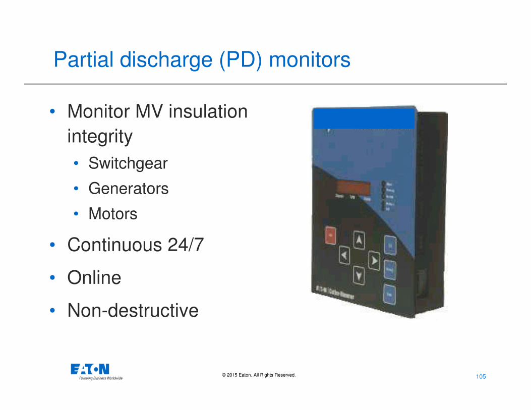
Partial discharge (PD) monitors
• Monitor MV insulation
integrity
• Switchgear
• Generators
• Motors
• Continuous 24/7
• Online
• Non-destructive
Page 106
106© 2015 Eaton. All Rights Reserved..
Stop MV switchgear failures
Page 107
107© 2015 Eaton. All Rights Reserved..
Results of partial discharges
Phase to phase discharges on ring
bus
49 MVA generator
Partial discharges on motor stator
Page 108
108© 2015 Eaton. All Rights Reserved..
Summary: Solutions that reduce arc flash injuries and equipment damage
• Take a System Approach
• Label Equipment & Minimize Risk
• Train Personnel On Proper Safety Practices
• Reduce Available Fault Current
• Redirect Blast Energy
• Faster Clearing Time
• Move People Farther Away
• Minimize The Probability of Faults Occurring
Page 109
109© 2015 Eaton. All Rights Reserved..
Questions?
Thank You!
Page 110
110© 2015 Eaton. All Rights Reserved..