70
Powermax30 ® AIR Plasma Arc Cutting System with Integrated Air Compressor Operator Manual 808840 | Revision 3 | English ARC WELDING SUPPLIES - 07 847 7870
Powermax30® AIRPlasma Arc Cutting System with Integrated Air Compressor
Operator Manual808840 | Revision 3 | English
ARC W
ELDIN
G SUPP
LIES
- 07 8
47 78
70
Powermax and Hypertherm are trademarks of Hypertherm Inc. and may be registered in the United States and other countries. All other trademarks are the property of their respective holders.
© 2016 Hypertherm Inc.
Register your new Hypertherm system
Register your product online at www.hypertherm.com/registration for easier technical and warranty support. You can also receive updates on new Hypertherm products and a free gift as a token of our appreciation.
For your records
Serial number:________________________________________________________________
Purchase date: _______________________________________________________________
Distributor: __________________________________________________________________
____________________________________________________________________________
____________________________________________________________________________
Maintenance notes:
____________________________________________________________________________
____________________________________________________________________________
____________________________________________________________________________
____________________________________________________________________________
____________________________________________________________________________
____________________________________________________________________________
ARC W
ELDIN
G SUPP
LIES
- 07 8
47 78
70

Powermax30 AIR
Operator Manual
808840Revision 3
English
January 2016
Hypertherm Inc.Hanover, NH 03755 USA
www.hypertherm.com
ARC W
ELDIN
G SUPP
LIES
- 07 8
47 78
70
Hypertherm Inc.Etna Road, P.O. Box 5010Hanover, NH 03755 USA603-643-3441 Tel (Main Office)603-643-5352 Fax (All Departments)[email protected] (Main Office Email)800-643-9878 Tel (Technical Service)[email protected] (Technical Service Email)800-737-2978 Tel (Customer Service)[email protected] (Customer Service Email)866-643-7711 Tel (Return Materials Authorization)877-371-2876 Fax (Return Materials Authorization)[email protected] (RMA email)
Hypertherm México, S.A. de C.V.Avenida Toluca No. 444, Anexo 1,Colonia Olivar de los PadresDelegación Álvaro ObregónMéxico, D.F. C.P. 0178052 55 5681 8109 Tel52 55 5683 2127 [email protected] (Technical Service Email)
Hypertherm Plasmatechnik GmbHSophie-Scholl-Platz 563452 Hanau Germany00 800 33 24 97 37 Tel00 800 49 73 73 29 Fax31 (0) 165 596900 Tel (Technical Service)00 800 4973 7843 Tel (Technical Service)[email protected] (Technical Service Email)
Hypertherm (Singapore) Pte Ltd.82 Genting LaneMedia CentreAnnexe Block #A01-01Singapore 349567, Republic of Singapore65 6841 2489 Tel65 6841 2490 Fax [email protected] (Marketing Email)[email protected] (Technical Service Email)
Hypertherm Japan Ltd.Level 9, Edobori Center Building2-1-1 Edobori, Nishi-kuOsaka 550-0002 Japan81 6 6225 1183 Tel81 6 6225 1184 [email protected] (Main Office Email)[email protected] (Technical Service Email)
Hypertherm Europe B.V.Vaartveld 9, 4704 SE Roosendaal, Nederland31 165 596907 Tel31 165 596901 Fax31 165 596908 Tel (Marketing)31 (0) 165 596900 Tel (Technical Service)00 800 4973 7843 Tel (Technical Service)[email protected] (Technical Service Email)
Hypertherm (Shanghai) Trading Co., Ltd.B301, 495 ShangZhong RoadShanghai, 200231PR China86-21-80231122 Tel86-21-80231120 Fax86-21-80231128 Tel (Technical Service)[email protected] (Technical Service Email)
South America & Central America: Hypertherm Brasil Ltda.Rua Bras Cubas, 231 – Jardim MaiaGuarulhos, SP – BrasilCEP 07115-03055 11 2409 2636 [email protected] (Technical Service Email)
Hypertherm Korea Branch#3904. APEC-ro 17. Heaundae-gu. Busan.Korea 4806082 (0)51 747 0358 Tel82 (0)51 701 0358 [email protected] (Marketing Email)[email protected] (Technical Service Email)
Hypertherm Pty LimitedGPO Box 4836 Sydney NSW 2001, Australia61 (0) 437 606 995 Tel61 7 3219 9010 [email protected] (Main Office Email)[email protected] (Technical Service Email)
Hypertherm (India) Thermal Cutting Pvt. LtdA-18 / B-1 Extension,Mohan Co-Operative Industrial Estate,Mathura Road, New Delhi 110044, India91-11-40521201/ 2/ 3 Tel91-11 40521204 [email protected] (Main Office Email)[email protected] (Technical Service Email)AR
C WEL
DING S
UPPLIE
S - 0
7 847
7870

ENGLISH
WARNING! Before operating any Hypertherm equipment, read the safety instructions in your product’s manual and in the Safety and Compliance Manual (80669C). Failure to follow safety instructions can result in personal injury or in damage to equipment.
Copies of the manuals may accompany the product in electronic and printed formats. You can also obtain copies of the manuals, in all languages available for each manual, from the “Downloads library” at www.hypertherm.com.
DEUTSCH / GERMAN
WARNUNG! Bevor Sie ein Hypertherm-Gerät in Betrieb nehmen, lesen Sie bitte die Sicherheitsanweisungen in Ihrer Bedienungsanleitung sowie im Handbuch für Sicherheit und Übereinstimmung (80669C). Das Nichtbefolgen der Sicherheitsanweisungen kann zu Verletzungen von Personen oder Schäden am Gerät führen.
Bedienungsanleitungen und Handbücher können dem Gerät in elektronischer Form oder als Druckversion beiliegen. Sie können alle Handbücher und Anleitungen in den jeweils verfügbaren Sprachen eines bestimmten Handbuchs auch in der „Download-Bibliothek“ unter www.hypertherm.com herunterladen.
FRANÇAIS / FRENCH
AVERTISSEMENT! Avant d’utiliser tout équipement Hypertherm, lire les consignes de sécurité importantes dans le manuel de votre produit et dans le Manuel de sécurité et de conformité (80669C). Le non-respect des consignes de sécurité peut engendrer des blessures physiques ou des dommages à l’équipement.
Des copies de ces manuels peuvent accompagner le produit en format électronique et papier. Vous pouvez également obtenir des copies de chaque manuel dans toutes les langues disponibles à partir de la « Bibliothèque de téléchargement » sur www.hypertherm.com.
ESPAÑOL / SPANISH
¡ADVERTENCIA! Antes de operar cualquier equipo Hypertherm, leer las instrucciones de seguridad del manual de su producto y del Manual de Seguridad y Cumplimiento (80669C). No cumplir las instrucciones de seguridad podría dar lugar a lesiones personales o daño a los equipos.
Pueden venir copias de los manuales en formato electrónico e impreso junto con el producto. También se pueden obtener copias de los manuales, en todos los idiomas disponibles para cada manual, de la “Biblioteca” en www.hypertherm.com.
ITALIANO / ITALIAN
AVVERTENZA! Prima di usare un’attrezzatura Hypertherm, leggere le istruzioni sulla sicurezza nel manuale del prodotto e nel Manuale sulla sicurezza e la conformità (80669C). Il mancato rispetto delle istruzioni sulla sicurezza può causare lesioni personali o danni all’attrezzatura.
Il prodotto può essere accompagnato da copie elettroniche e cartacee del manuale. È anche possibile ottenere copie del manuale, in tutte le lingue disponibili per ogni manuale, da “Archivio download” all’indirizzo www.hypertherm.com.
NEDERLANDS / DUTCH
WAARSCHUWING! Lees voordat u Hypertherm-apparatuur gebruikt de veiligheidsinstructies in de producthandleiding en in de Veiligheids- en nalevingshandleiding (80669C). Het niet volgen van de veiligheidsinstructies kan resulteren in persoonlijk letsel of schade aan apparatuur.
De handleidingen kunnen in elektronische en gedrukte vorm met het product worden meegeleverd. De handleidingen, elke handleiding beschikbaar in alle talen, zijn ook verkrijgbaar via de “Downloadbibliotheek” op www.hypertherm.com.
DANSK / DANISH
ADVARSEL! Inden Hypertherm udstyr tages i brug skal sikkerhedsinstruktionerne i produktets manual og i Manual om sikkerhed og overholdelse af krav (80669C), gennemlæses. Følges sikkerhedsvejledningen ikke kan det resultere i personskade eller beskadigelse af udstyret.
Kopier af manualerne kan ledsage produktet i elektroniske og trykte formater. Du kan også få kopier af manualer, på alle sprog der er til rådighed for hver manuel, fra "Download-biblioteket" på www.hypertherm.com.
PORTUGUÊS / PORTUGUESE
ADVERTÊNCIA! Antes de operar qualquer equipamento Hypertherm, leia as instruções de segurança no manual do seu produto e no Manual de Segurança e de Conformidade (80669C). Não seguir as instruções de segurança pode resultar em lesões corporais ou danos ao equipamento.
Cópias dos manuais podem acompanhar os produtos nos formatos eletrônico e impresso. Também é possível obter cópias dos manuais em todos os idiomas disponíveis para cada manual na “Biblioteca de downloads” em www.hypertherm.com.
日本語 / JAPANESE
警告 ! Hypertherm 機器を操作する前に、安全に関する重要な情報について、この製品説明書にある安全情報、および製品に同梱されている別冊の「安全とコンプライアンスマニュアル」 (80669C) をお読みください。安全情報に従わないと怪我や装置の損傷を招くことがあります。説明書のコピーは、電子フォーマット、または印刷物として製品に同梱されています。各説明書は、 www.hypertherm.com の「ダンロードライブラリ」から各言語で入手できます。
简体中文 / CHINESE (SIMPLIFIED)
警告! 在操作任何海宝设备之前,请阅读产品手册和《安全和法规遵守手
册》 (80669C) 中的安全操作说明。若未能遵循安全操作说明,可能会造成
人员受伤或设备损坏。
随产品提供的手册可能提供电子版和印刷版两种格式。您也可从
“Downloads library” (下载资料库)中获取每本手册所有可用语言的副本,
网址为 www.hypertherm.com.
NORSK / NORWEGIAN
ADVARSEL! Før du bruker noe Hypertherm-utstyr, må du lese sikkerhetsinstruksjonene i produktets håndbok og i Håndboken om sikkerhet og samsvar (80669C). Unnlatelse av å følge sikkerhetsinstruksjoner kan føre til personskade eller skade på utstyr.
Eksemplarer av håndbøkene kan medfølge produktet i elektroniske og trykte utgaver. Du kan også få eksemplarer av håndbøkene, i alle tilgjengelige språk for hver håndbok, fra "nedlastningsbiblioteket" på www.hypertherm.com.
SVENSKA / SWEDISH
VARNING! Läs häftet säkerhetsinformationen i din produkts säkerhets- och efterlevnadsmanual (80669C) för viktig säkerhetsinformation innan du använder eller underhåller Hypertherm-utrustning. Underlåtenhet att följa dessa säkerhetsinstruktionerkan resultera i personskador eller skador på utrustningen.
Kopior av manualen kan medfölja produkten i elektronisk och tryckform. Du hittar även kopior av manualerna i alla tillgängliga språk i ”nedladdningsbiblioteket” (Downloads library) på www.hypertherm.com.
한국어 / KOREAN
경고 ! Hypertherm 장비를 사용하기 전에 제품 설명서와 안전 및 규정 준수 설명서 (80669C) 에 나와 있는 안전 지침을 읽으십시오 . 안전 지침을 준수하지 않으면 신체 부상이나 장비 손상을 초래할 수 있습니다 .전자 형식과 인쇄된 형식으로 설명서 사본이 제품과 함께 제공될 수 있습니다 . www.hypertherm.com 의 'Downloads library( 다운로드 라이브러리 )' 에서도 모든 언어로 이용할 수 있는 설명서 사본을 얻을 수 있습니다 .
ARC W
ELDIN
G SUPP
LIES
- 07 8
47 78
70

ČESKY / CZECH
VAROVÁNÍ! Před uvedením jakéhokoliv zařízení Hypertherm do provozu si přečtěte bezpečnostní pokyny v příručce k produktu a v Manuálu pro bezpečnost a dodržování předpisů (80669G). Nedodržování bezpečnostních pokynů může mít za následek zranění osob nebo poškození majetku.
Kopie příruček a manuálů mohou být součástí dodávky produktu, a to v elektronické i tištěné formě. Kopie příruček a manuálů ve všech jazykových verzích, v nichž byly dané příručky a manuály vytvořeny, naleznete v „Knihovně ke stažení“ na webových stránkách www.hypertherm.com.
POLSKI / POLISH
OSTRZEŻENIE! Przed rozpoczęciem obsługi jakiegokolwiek systemu firmy Hypertherm należy się zapoznać z instrukcjami bezpieczeństwa zamieszczonymi w podręczniku produktu oraz w Podręczniku bezpieczeństwa i zgodności (80669C). Nieprzestrzeganie instrukcji bezpieczeństwa może skutkować obrażeniami ciała i uszkodzeniem sprzętu.
Do produktu mogą być dołączone kopie podręczników w formacie elektronicznym i drukowanym. Kopie podręczników, w każdym udostępnionym języku, można również znaleźć w „Bibliotece materiałów do pobrania” pod adresem www.hypertherm.com.
PУССКИЙ / RUSSIAN
БЕРЕГИСЬ! Перед работой с любым оборудованием Hypertherm ознакомьтесь с инструкциями по безопасности, представленными в руководстве, которое поставляется вместе с продуктом, а также в Руководстве по безопасности и соответствию (80669J). Невыполнение инструкций по безопасности может привести к телесным повреждениям или повреждению оборудования.
Копии руководств, которые поставляются вместе с продуктом, могут быть представлены в электронном и бумажном виде. Копии руководств на всех языках, на которые переведено то или иное руководство, можно также загрузить из раздела «Библиотека документов» на веб-сайте www.hypertherm.com.
SUOMI / FINNISH
VAROITUS! Ennen minkään Hypertherm-laitteen käyttöä lue tuotteen käyttöoppaassa olevat turvallisuusohjeet ja turvallisuus- ja vaatimustenmukaisuusohje (80669C). Turvallisuusohjeiden laiminlyönti voi aiheuttaa henkilökohtaisen loukkaantumisen tai laitevahingon.
Käyttöoppaiden kopiot voivat olla tuotteen mukana elektronisessa ja tulostetussa muodossa. Voit saada käyttöoppaiden kopiot kaikilla kielillä ”latauskirjastosta” osoitteessa www.hypertherm.com.
БЪЛГAPCКИ / BULGARIAN
ПРЕДУПРЕЖДЕНИЕ! Преди да работите с което и да е оборудване Hypertherm, прочетете инструкциите за безопасност в ръководството на вашия продукт и „Инструкция за безопасност и съответствие“ (80669C). Неспазването на инструкциите за безопасност би могло да доведе до телесно нараняване или до повреда на оборудването.
Копия на ръководствата може да придружават продукта в електронен и в печатен формат. Можете да получите копия на ръководствата, предлагани на всички езици, от “Downloads library” (Библиотека за теглене) на адрес www.hypertherm.com.
ROMÂNĂ / ROMANIAN
AVERTIZARE! Înainte de utilizarea oricărui echipament Hypertherm, citiți instrucțiunile de siguranță din cadrul manualului produsului și din cadrul Manualului de siguranță și conformitate (80669C). Nerespectarea instrucțiunilor de siguranță pot rezulta în vătămare personală sau în avarierea echipamentului.
Produsul poate fi însoțit de copii ale manualului în format tipărit și electronic. De asemenea, dumneavoastră puteți obține copii ale manualelor, în toate limbile disponibile pentru fiecare manual, din cadrul secțiunii ”Librărie de descărcare” aflată pe site-ul www.hypertherm.com.
TÜRKÇE / TURKISH
UYARI! Bir Hypertherm ekipmanını çalıştırmadan önce, ürün kullanım kılavuzunda ve Güvenlik ve Uyumluluk Kılavuzu’nda (80669C) yer alan güvenlik talimatlarını okuyun. Güvenlik talimatlarına uyulmaması durumunda kişisel yaralanmalar veya ekipman hasarı meydana gelebilir.
Kılavuzların kopyaları, elektronik ve basılı formatta ürünle birlikte verilebilir. Her biri tüm dillerde yayınlanan kılavuzların kopyalarını www.hypertherm.com adresindeki “Downloads library” (Yüklemeler kitaplığı) başlığından da elde edebilirsiniz.
MAGYAR / HUNGARIAN
VIGYÁZAT! Mielőtt bármilyen Hypertherm berendezést üzemeltetne, olvassa el a biztonsági információkat a termék kézikönyvében és a Biztonsági és szabálykövetési kézikönyvben (80669C). A biztonági utasítások betartásának elmulasztása személyi sérüléshez vagy a berendezés károsodásához vezethet.
A termékhez a kézikönyv példányai elektronikus és nyomtatott formában is mellékelve lehetnek. A kézikönyvek példányai (minden nyelven) a www.hypertherm.com weboldalon a „Downloads library” (Letöltési könyvtár) részben is beszerezhetők.
ΕΛΛΗΝΙΚΆ / GREEK
ΠΡΟΕΙΔΟΠΟΙΗΣΗ! Πριν θέσετε σε λειτουργία οποιονδήποτε εξοπλισμό της Hypertherm, διαβάστε τις οδηγίες ασφαλείας στο εγχειρίδιο του προϊόντος και στο Εγχειρίδιο ασφάλειας και συμμόρφωσης (80669C). Η μη τήρηση των οδηγιών ασφαλείας μπορεί να επιφέρει σωματική βλάβη ή ζημιά στον εξοπλισμό.
Αντίγραφα των εγχειριδίων μπορεί να συνοδεύουν το προϊόν σε ηλεκτρονική και έντυπη μορφή. Μπορείτε, επίσης, να λάβετε αντίγραφα των εγχειριδίων σε όλες τις γλώσσες που διατίθενται για κάθε εγχειρίδιο από την ψηφιακή βιβλιοθήκη λήψεων (Downloads library) στη διαδικτυακή τοποθεσία www.hypertherm.com.
繁體中文 / CHINESE (TRADITIONAL)
警告! 在操作任何 Hypertherm 設備前,請閱讀您產品手冊和 《安全和法務遵從手冊》(80669C) 內的安全指示。 不遵守安全指示可能會導致人身傷害或設備損壞。手冊複本可能以電子和印刷格式隨附產品提供。您也可以在 www.hypertherm.com 的 「下載資料庫」內獲取所有手冊的多語種複本。
SLOVENŠČINA / SLOVENIAN
OPOZORILO! Pred uporabo katerekoli Hyperthermove opreme preberite varnostna navodila v priročniku vašega izdelka ter v Priročniku za varnost in skladnost (80669C). Neupoštevanje navodil za uporabo lahko povzroči telesne poškodbe ali materialno škodo.
Izdelku so lahko priloženi izvodi priročnikov v elektronski ali tiskani obliki. Izvode priročnikov v vseh razpoložljivih jezikih si lahko prenesete tudi iz knjižnice prenosov “Downloads library” na naslovu www.hypertherm.com.
SRPSKI / SERBIAN
UPOZORENJE! Pre rukovanja bilo kojom Hyperthermovom opremom pročitajte uputstva o bezbednosti u svom priručniku za proizvod i u Priručniku o bezbednosti i usaglašenosti (80669C). Oglušavanje o praćenje uputstava o bezbednosti može da ima za posledicu ličnu povredu ili oštećenje opreme.
Može se dogoditi da kopije priručnika prate proizvod u elektronskom i štampanom formatu. Takođe možete da pronađete kopije priručnika, na svim jezicima koji su dostupni za svaki od priručnika, u “Biblioteci preuzimanja” (“Downloads library”) na www.hypertherm.com.
SLOVENSKÝ / SLOVAK
VÝSTRAHA! Pred použitím akéhokoľvek zariadenia od spoločnosti Hypertherm si prečítajte bezpečnostné pokyny v návode na obsluhu vášho zariadenia a v Manuáli o bezpečnosti a súlade s normami (80669C). V prípade nedodržania bezpečnostných pokynov môže dôjsť k ujme na zdraví alebo poškodeniu zariadenia.
Kópia návodu, ktorá je dodávaná s produktom, môže mať elektronickú alebo tlačenú podobu. Kópie návodov, vo všetkých dostupných jazykoch, sú k dispozícii aj v sekcii “Downloads library” na www.hypertherm.com.
ARC W
ELDIN
G SUPP
LIES
- 07 8
47 78
70
70
Contents
Electromagnetic Compatibility (EMC) ............................................................................SC-11Introduction ..............................................................................................................................................................................SC-11Installation and use .................................................................................................................................................................SC-11Assessment of area ................................................................................................................................................................SC-11Methods of reducing emissions ..........................................................................................................................................SC-11
Mains supply ....................................................................................................................................................................SC-11Maintenance of cutting equipment .....................................................................................................................................SC-11Cutting cables .........................................................................................................................................................................SC-11
Equipotential bonding ....................................................................................................................................................SC-11Earthing of the workpiece .............................................................................................................................................SC-12
Screening and shielding .......................................................................................................................................................SC-12
Warranty ..................................................................................................................................SC-13Attention ....................................................................................................................................................................................SC-13General .....................................................................................................................................................................................SC-13Patent indemnity .....................................................................................................................................................................SC-13Limitation of liability ................................................................................................................................................................SC-13National and local codes .......................................................................................................................................................SC-13Liability cap ..............................................................................................................................................................................SC-13Insurance ..................................................................................................................................................................................SC-14Transfer of rights .....................................................................................................................................................................SC-14
1 Specifications .............................................................................................................................. 15Safety information ......................................................................................................................................................................... 15System description ....................................................................................................................................................................... 15Power supply dimensions ........................................................................................................................................................... 16System weights ............................................................................................................................................................................. 16Hypertherm system ratings ......................................................................................................................................................... 17
ARC W
ELDIN
G SUPP
LIES
- 07 8
47 78
Powermax30 AIR Operator Manual 808840 7

Contents
Torch dimensions ......................................................................................................................................................................... 18Torch weight .................................................................................................................................................................................. 18Cutting specifications .................................................................................................................................................................. 19IEC symbols ................................................................................................................................................................................... 20Noise levels .................................................................................................................................................................................... 20Symbols and marks ...................................................................................................................................................................... 21
2 Power Supply Setup .................................................................................................................. 23Unpack the plasma system ........................................................................................................................................................ 23
Claims ...................................................................................................................................................................................... 23System contents ........................................................................................................................................................................... 24Position the plasma cutting system .......................................................................................................................................... 25Prepare the electrical power ...................................................................................................................................................... 25
Voltage configurations ......................................................................................................................................................... 25Requirements for grounding .............................................................................................................................................. 27
Power cord considerations ........................................................................................................................................................ 27CSA power cords and plugs ............................................................................................................................................. 27CE and CCC power cords ................................................................................................................................................ 28
Install a plug on the power cord ................................................................................................................................ 28Extension cord recommendations ..................................................................................................................................... 29Generator recommendations ............................................................................................................................................. 29
3 Torch Setup .................................................................................................................................. 31Introduction .................................................................................................................................................................................... 31
Hand torch components ..................................................................................................................................................... 31Consumable life ............................................................................................................................................................................ 32Consumable use ........................................................................................................................................................................... 33
Using the cut charts ............................................................................................................................................................. 33Consumable set .................................................................................................................................................................... 34
240 V / 30 A cutting .................................................................................................................................................... 35120 V / 20 A cutting .................................................................................................................................................... 37
ARC W
ELDIN
G SUPP
LIES
- 07 8
47 78
70
8 Powermax30 AIR Operator Manual 808840

Contents
4 Operation ...................................................................................................................................... 39Controls and indicators ............................................................................................................................................................... 39
Rear controls .......................................................................................................................................................................... 39Front panel controls and indicator LED symbols ........................................................................................................... 40
Operate the plasma system ....................................................................................................................................................... 41Step 1 – Install the consumables ..................................................................................................................................... 41Step 2 – Connect the electrical power ........................................................................................................................... 42Step 3 – Adjust the output current ................................................................................................................................... 43
Operating the system on a 120 V / 20 A circuit ................................................................................................... 43Operating the system on a 240 V / 20 A circuit ................................................................................................... 43Decrease output current for lower-rated power plugs ......................................................................................... 43Cutting expanded metal .............................................................................................................................................. 43
Step 4 – Attach the ground clamp ................................................................................................................................... 44Step 5 – Power ON the system ........................................................................................................................................ 44Step 6 – Check the indicator LEDs ................................................................................................................................. 44Step 7 – Make sure the system is ready, and start cutting ........................................................................................ 45
What to expect during and after cutting ................................................................................................................................. 45Water at the torch nozzle .................................................................................................................................................... 45Postflow .................................................................................................................................................................................. 45Internal compressor and fan activity ................................................................................................................................. 45Water under the power supply .......................................................................................................................................... 45
Understand duty-cycle limitations ............................................................................................................................................. 46System operation guidelines ...................................................................................................................................................... 47Hand torch operation ................................................................................................................................................................... 48
Safety catch operation ......................................................................................................................................................... 48Hand torch cutting guidelines ............................................................................................................................................ 49
Recommendations for cutting at 120 V ................................................................................................................... 49Edge start on a workpiece .................................................................................................................................................. 50Pierce a workpiece ............................................................................................................................................................... 51Common hand-cutting faults .............................................................................................................................................. 52
Minimizing dross ............................................................................................................................................................ 52
ARC W
ELDIN
G SUPP
LIES
- 07 8
47 78
70
Powermax30 AIR Operator Manual 808840 9

Contents
5 Maintenance and Troubleshooting ....................................................................................... 53Perform routine maintenance ..................................................................................................................................................... 53Inspect the consumables ............................................................................................................................................................ 55Basic troubleshooting .................................................................................................................................................................. 56
Power LED faults .................................................................................................................................................................. 56Temperature LED faults ....................................................................................................................................................... 57Internal compressor LED faults ......................................................................................................................................... 58Torch LED faults ................................................................................................................................................................... 59Common cutting issues ...................................................................................................................................................... 60
6 Parts ............................................................................................................................................... 63Power supply parts ...................................................................................................................................................................... 64
Exterior, front .......................................................................................................................................................................... 64Exterior, rear ........................................................................................................................................................................... 65
Hand torch consumables ............................................................................................................................................................ 66Accessory parts ............................................................................................................................................................................ 67Power supply labels ..................................................................................................................................................................... 68
Consumables label ............................................................................................................................................................... 68CSA warning label ............................................................................................................................................................... 69CE/CCC warning label ....................................................................................................................................................... 70
ARC W
ELDIN
G SUPP
LIES
- 07 8
47 78
70
10 Powermax30 AIR Operator Manual 808840

Electromagnetic Compatibility (EMC)
IntroductionHypertherm’s CE-marked equipment is built in compliance with standard EN60974-10. The equipment should be installed and used in accordance with the information below to achieve electromagnetic compatibility.
The limits required by EN60974-10 may not be adequate to completely eliminate interference when the affected equipment is in close proximity or has a high degree of sensitivity. In such cases it may be necessary to use other measures to further reduce interference.
This cutting equipment is designed for use only in an industrial environment.
Installation and useThe user is responsible for installing and using the plasma equipment according to the manufacturer’s instructions.
If electromagnetic disturbances are detected then it shall be the responsibility of the user to resolve the situation with the technical assistance of the manufacturer. In some cases this remedial action may be as simple as earthing the cutting circuit, see Earthing of the workpiece. In other cases, it could involve constructing an electromagnetic screen enclosing the power source and the work complete with associated input filters. In all cases, electromagnetic disturbances must be reduced to the point where they are no longer troublesome.
Assessment of areaBefore installing the equipment, the user shall make an assessment of potential electromagnetic problems in the surrounding area. The following shall be taken into account:
a. Other supply cables, control cables, signaling and telephone cables; above, below and adjacent to the cutting equipment.
b. Radio and television transmitters and receivers.
c. Computer and other control equipment.
d. Safety critical equipment, for example guarding of industrial equipment.
e. Health of the people around, for example the use of pacemakers and hearing aids.
f. Equipment used for calibration or measurement.
g. Immunity of other equipment in the environment. User shall ensure that other equipment being used in the environment is compatible. This may require additional protection measures.
h. Time of day that cutting or other activities are to be carried out.
The size of the surrounding area to be considered will depend on the structure of the building and other activities that are taking place. The surrounding area may extend beyond the boundaries of the premises.
Methods of reducing emissionsMains supply
Cutting equipment must be connected to the mains supply according to the manufacturer’s recommendations. If interference occurs, it may be necessary to take additional precautions such as filtering of the mains supply.
Consideration should be given to shielding the supply cable of permanently installed cutting equipment, in metallic conduit or equivalent. Shielding should be electrically continuous throughout its length. The shielding should be connected to the cutting mains supply so that good electrical contact is maintained between the conduit and the cutting power source enclosure.
Maintenance of cutting equipmentThe cutting equipment must be routinely maintained according to the manufacturer’s recommendations. All access and service doors and covers should be closed and properly fastened when the cutting equipment is in operation. The cutting equipment should not be modified in any way, except as set forth in and in accordance with the manufacturer’s written instructions. For example, the spark gaps of arc striking and stabilizing devices should be adjusted and maintained according to the manufacturer’s recommendations.
Cutting cablesThe cutting cables should be kept as short as possible and should be positioned close together, running at or close to the floor level.
Equipotential bonding
Bonding of all metallic components in the cutting installation and adjacent to it should be considered.
However, metallic components bonded to the workpiece will increase the risk that the operator could receive a shock by touching these metallic components and the electrode (nozzle for laser heads) at the same time.
The operator should be insulated from all such bonded metallic components.
ARC W
ELDIN
G SUPP
LIES
- 07 8
47 78
70
Safety and compliance SC-11

Electromagnetic Compatibility (EMC)
Earthing of the workpiece
Where the workpiece is not bonded to earth for electrical safety, nor connected to earth because of its size and position, for example, ship’s hull or building steel work, a connection bonding the workpiece to earth may reduce emissions in some, but not all instances. Care should be taken to prevent the earthing of the workpiece increasing the risk of injury to users, or damage to other electrical equipment. Where necessary, the connection of the workpiece to earth should be made by a direct connection to the workpiece, but in some countries where direct connection is not permitted, the bonding should be achieved by suitable capacitances selected according to national regulations.
Note: The cutting circuit may or may not be earthed for safety reasons. Changing the earthing arrangements should only be authorized by a person who is competent to assess whether the changes will in crease the risk of injury, for example, by allowing parallel cutting current return paths which may damage the earth circuits of other equipment. Further guidance is provided in IEC 60974-9, Arc Welding Equipment, Part 9: Installation and Use.
Screening and shieldingSelective screening and shielding of other cables and equipment in the surrounding area may alleviate problems of interference. Screening of the entire plasma cutting installation may be considered for special applications.
ARC W
ELDIN
G SUPP
LIES
- 07 8
47 78
70
SC-12 Safety and compliance

Warranty
AttentionGenuine Hypertherm parts are the factory-recommended replacement parts for your Hypertherm system. Any damage or injury caused by the use of other than genuine Hypertherm parts may not be covered by the Hypertherm warranty, and will constitute misuse of the Hypertherm Product.
You are solely responsible for the safe use of the Product. Hypertherm does not and cannot make any guarantee or warranty regarding the safe use of the product in your environment.
GeneralHypertherm Inc. warrants that its Products shall be free from defects in materials and workmanship for the specific periods of time set forth herein and as follows: if Hypertherm is notified of a defect (i) with respect to the plasma power supply within a period of two (2) years from the date of its delivery to you, with the exception of Powermax brand power supplies, which shall be within a period of three (3) years from the date of delivery to you, and (ii) with respect to the torch and leads within a period of one (1) year from its date of delivery to you, with the exception of the HPRXD short torch with integrated lead, which shall be within a period of six (6) months from the date of delivery to you, and with respect to torch lifter assemblies within a period of one (1) year from its date of delivery to you, and with respect to Automation products one (1) year from its date of delivery to you, with the exception of the EDGE Pro CNC, EDGE Pro Ti CNC, MicroEDGE Pro CNC, and ArcGlide THC, which shall be within a period of two (2) years from the date of delivery to you, and (iii) with respect to HyIntensity fiber laser components within a period of two (2) years from the date of its delivery to you, with the exception of laser heads and beam delivery cables, which shall be within a period of one (1) year from its date of delivery to you.
This warranty shall not apply to any Powermax brand power supplies that have been used with phase converters. In addition, Hypertherm does not warranty systems that have been damaged as a result of poor power quality, whether from phase converters or incoming line power. This warranty shall not apply to any product which has been incorrectly installed, modified, or otherwise damaged.
Hypertherm provides repair, replacement or adjustment of the Product as the sole and exclusive remedy, if and only if the warranty set forth herein properly is invoked and applies. Hypertherm, at its sole option, shall repair, replace, or adjust, free of charge, any defective Products covered by this warranty which shall be returned with Hypertherm’s prior authorization (which shall not be unreasonably withheld), properly packed, to Hypertherm’s place of business in Hanover, New Hampshire, or to an authorized Hypertherm repair facility, all costs, insurance and freight pre paid by the customer. Hypertherm shall not be liable for any repairs, replacement, or adjustments of Products covered by this warranty, except those made pursuant to this paragraph and with Hypertherm’s prior written consent.
The warranty set forth above is exclusive and is in lieu of all other warranties, express, implied, statutory, or otherwise with respect to the Products or as to the results which may be obtained therefrom, and all implied warranties or conditions of quality or of merchantability or fitness for a particular purpose or against infringement. The foregoing shall constitute the sole and exclusive remedy for any breach by Hypertherm of its warranty.
Distributors/OEMs may offer different or additional warranties, but Distributors/OEMs are not authorized to give any additional warranty protection to you or make any representation to you purporting to be binding upon Hypertherm.
Patent indemnityExcept only in cases of products not manufactured by Hypertherm or manufactured by a person other than Hypertherm not in strict conformity with Hypertherm’s specifications and in cases of designs, processes, formulae, or combinations not developed or purported to be developed by Hypertherm, Hypertherm will have the right to defend or settle, at its own expense, any suit or proceeding brought against you alleging that the use of the Hypertherm product, alone and not in combination with any other product not supplied by Hypertherm, infringes any patent of any third party. You shall notify Hypertherm promptly upon learning of any action or threatened action in connection with any such alleged infringement (and in any event no longer than fourteen (14) days after learning of any action or threat of action), and Hypertherm’s obligation to defend shall be conditioned upon Hypertherm’s sole control of, and the indemnified party’s cooperation and assistance in, the defense of the claim.
Limitation of liabilityIn no event shall Hypertherm be liable to any person or entity for any incidental, consequential direct, indirect, punitive or exemplary damages (including but not limited to lost profits) regardless of whether such liability is based on breach of contract, tort, strict liability, breach of warranty, failure of essential purpose, or otherwise, and even if advised of the possibility of such damages.
National and local codesNational and local codes governing plumbing and electrical installation shall take precedence over any instructions contained in this manual. In no event shall Hypertherm be liable for injury to persons or property damage by reason of any code violation or poor work practices.
Liability capIn no event shall Hypertherm’s liability, if any, whether such liability is based on breach of contract, tort, strict liability, breach of warranties, failure of essential purpose or otherwise, for any claim, action, suit or proceeding (whether in court, arbitration, regulatory proceeding or otherwise) arising out of or relating to the use of the Products exceed in the aggregate the amount paid for the Products that gave rise to such claim.
ARC W
ELDIN
G SUPP
LIES
- 07 8
47 78
70
Safety and compliance SC-13
Warranty
InsuranceAt all times you will have and maintain insurance in such quantities and types, and with coverage sufficient and appropriate to defend and to hold Hypertherm harmless in the event of any cause of action arising from the use of the products.
Transfer of rightsYou may transfer any remaining rights you may have hereunder only in connection with the sale of all or substantially all of your assets or capital stock to a successor in interest who agrees to be bound by all of the terms and conditions of this Warranty. Within thirty (30) days before any such transfer occurs, you agree to notify in writing Hypertherm, which reserves the right of approval. Should you fail timely to notify Hypertherm and seek its approval as set forth herein, the Warranty set forth herein shall be null and void and you will have no further recourse against Hypertherm under the Warranty or otherwise.
ARC W
ELDIN
G SUPP
LIES
- 07 8
47 78
70
SC-14 Safety and compliance
70
Section 1
Specifications
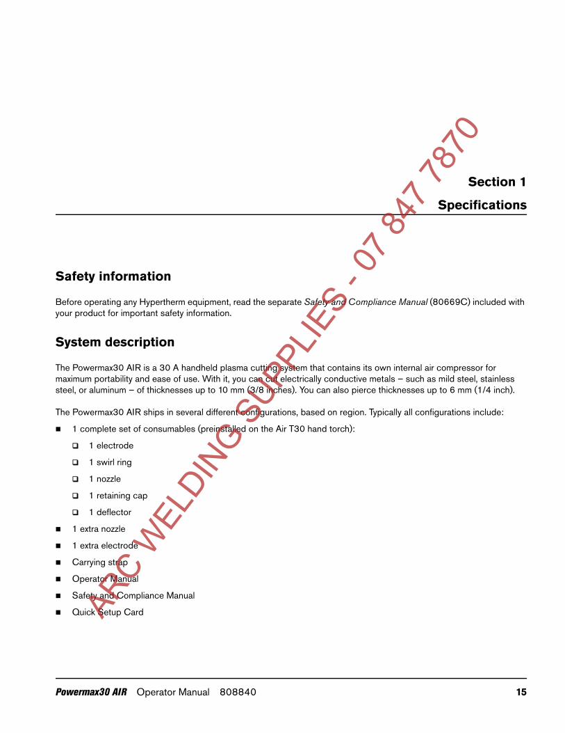
Safety information
Before operating any Hypertherm equipment, read the separate Safety and Compliance Manual (80669C) included with your product for important safety information.
System description
The Powermax30 AIR is a 30 A handheld plasma cutting system that contains its own internal air compressor for maximum portability and ease of use. With it, you can cut electrically conductive metals – such as mild steel, stainless steel, or aluminum – of thicknesses up to 10 mm (3/8 inches). You can also pierce thicknesses up to 6 mm (1/4 inch).
The Powermax30 AIR ships in several different configurations, based on region. Typically all configurations include:
1 complete set of consumables (preinstalled on the Air T30 hand torch):
1 electrode
1 swirl ring
1 nozzle
1 retaining cap
1 deflector
1 extra nozzle
1 extra electrode
Carrying strap
Operator Manual
Safety and Compliance Manual
Quick Setup CardARC W
ELDIN
G SUPP
LIES
- 07 8
47 78
Powermax30 AIR Operator Manual 808840 15

1 – Specifications
CSA units ship with a 120 V / 15 A (NEMA 5-15P) adapter and a 240 V / 20 A (NEMA 6-50P) adapter that connect to the NEMA twist lock-style 240 V / 20 A (NEMA L6-20P) plug wired to the power supply. CE and CCC units ship without a plug on the power cord. See Power cord considerations on page 27 for more information.
You can order additional consumables and accessories – such as a dust cover and circle cutting guides, for example – from any Hypertherm distributor. See Parts on page 63 for a list of spare and optional parts.
Power supply dimensions
System weights
The following system weights include the hand torch with 4.6 m (15 foot) torch lead, a 4.6 m (15 foot) work lead with ground clamp, and a 3.0 m (10 foot) power cord:
CSA systems: 13.5 kg (29.8 pounds)
CE and CCC systems: 13.4 kg (29.5 pounds)
420 mm(16.5 inches)
195 mm(7.7 inches)
333 mm(13.1 inches)
295 mm(11.6 inches)
ARC W
ELDIN
G SUPP
LIES
- 07 8
47 78
70
16 Powermax30 AIR Operator Manual 808840
1 – Specifications
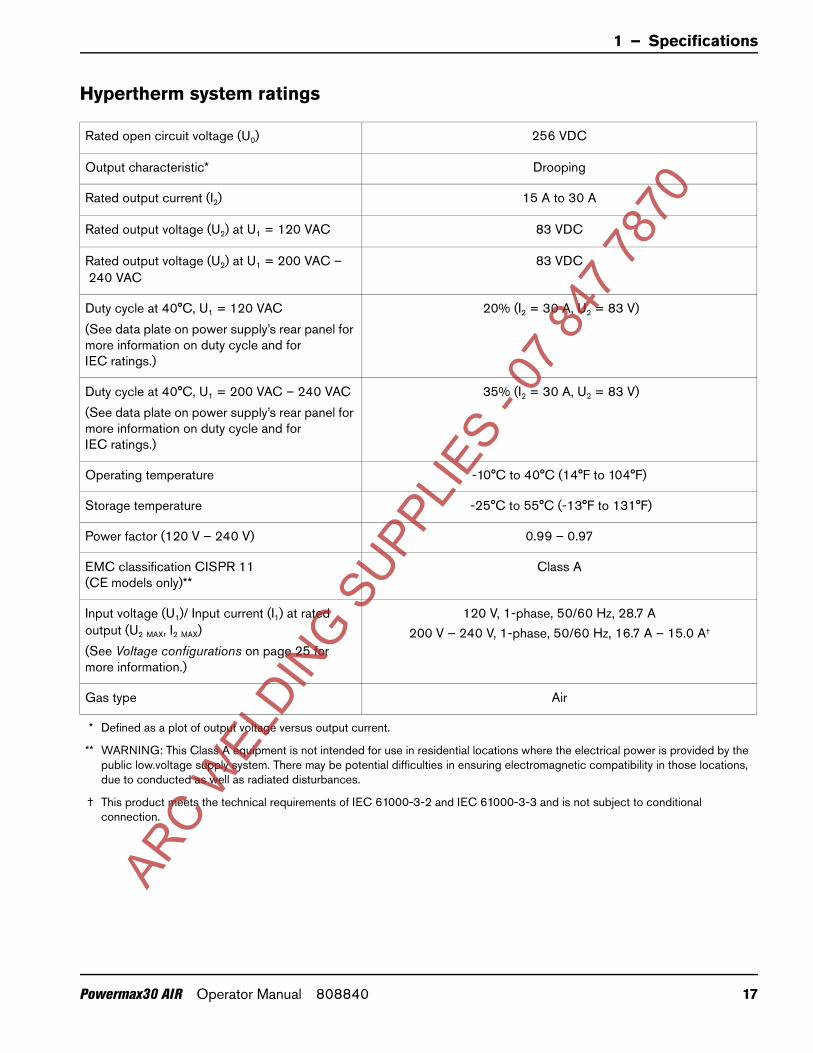
Hypertherm system ratings
Rated open circuit voltage (U0) 256 VDC
Output characteristic* Drooping
Rated output current (I2) 15 A to 30 A
Rated output voltage (U2) at U1 = 120 VAC 83 VDC
Rated output voltage (U2) at U1 = 200 VAC –240 VAC
83 VDC
Duty cycle at 40°C, U1 = 120 VAC(See data plate on power supply’s rear panel for more information on duty cycle and for IEC ratings.)
20% (I2 = 30 A, U2 = 83 V)
Duty cycle at 40°C, U1 = 200 VAC – 240 VAC(See data plate on power supply’s rear panel for more information on duty cycle and for IEC ratings.)
35% (I2 = 30 A, U2 = 83 V)
Operating temperature -10°C to 40°C (14°F to 104°F)
Storage temperature -25°C to 55°C (-13°F to 131°F)
Power factor (120 V – 240 V) 0.99 – 0.97
EMC classification CISPR 11 (CE models only)**
Class A
Input voltage (U1)/ Input current (I1) at rated output (U2 MAX, I2 MAX)(See Voltage configurations on page 25 for more information.)
120 V, 1-phase, 50/60 Hz, 28.7 A200 V – 240 V, 1-phase, 50/60 Hz, 16.7 A – 15.0 A†
Gas type Air
* Defined as a plot of output voltage versus output current.
** WARNING: This Class A equipment is not intended for use in residential locations where the electrical power is provided by the public low.voltage supply system. There may be potential difficulties in ensuring electromagnetic compatibility in those locations, due to conducted as well as radiated disturbances.
† This product meets the technical requirements of IEC 61000-3-2 and IEC 61000-3-3 and is not subject to conditional connection.
ARC W
ELDIN
G SUPP
LIES
- 07 8
47 78
70
Powermax30 AIR Operator Manual 808840 17

1 – Specifications
Torch dimensions
Torch weight
Air T30 torch with consumables only: 0.3 kg (0.65 pounds)
Air T30 torch with consumables and 4.6 m (15 foot) lead (with strain relief): 1.0 kg (2.25 pounds)
25 mm(1.0 inch)
51 mm (2.0 inches)
230 mm (9.0 inches)
45 mm(1.8 inches)
86 mm(3.4 inches)
75°
ARC W
ELDIN
G SUPP
LIES
- 07 8
47 78
70
18 Powermax30 AIR Operator Manual 808840

1 – Specifications
Cutting specifications
240 V
Recommended cut capacity* 8 mm (5/16 inch) at a minimum of 500 mm/minute (20 inches/minute)10 mm (3/8 inch) at a minimum of 250 mm/minute (10 inches/minute)
Severance cut capacity 16 mm (5/8 inch) at a minimum of 125 mm/minute (5 inches/minute)
* When you operate this system at altitudes higher than 2,200 m (7,500 feet) above sea level, you may experience some reduction in cutting performance due to the adverse effect that altitude has on air compressors.
120 V
When you operate the system at the maximum recommended output of 20 A, the cut capacities are:
3 mm (10 gauge) at 762 mm/minute (30 inches/minute)
6 mm (1/4 inch) at 355 mm/minute (14 inches/minute)
10 mm (3/8 inch) at 125 mm/minute (5 inches/minute)
ARC W
ELDIN
G SUPP
LIES
- 07 8
47 78
70
Powermax30 AIR Operator Manual 808840 19
1 – Specifications
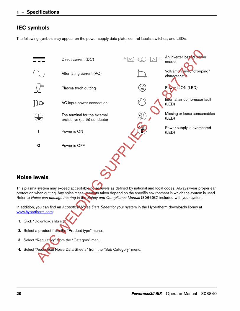
IEC symbols
The following symbols may appear on the power supply data plate, control labels, switches, and LEDs.
Noise levels
This plasma system may exceed acceptable noise levels as defined by national and local codes. Always wear proper ear protection when cutting. Any noise measurements taken depend on the specific environment in which the system is used. Refer to Noise can damage hearing in the Safety and Compliance Manual (80669C) included with your system.
In addition, you can find an Acoustical Noise Data Sheet for your system in the Hypertherm downloads library at www.hypertherm.com:
1. Click “Downloads library.”
2. Select a product from the “Product type” menu.
3. Select “Regulatory” from the “Category” menu.
4. Select “Acoustical Noise Data Sheets” from the “Sub Category” menu.
Direct current (DC)
Alternating current (AC)
Plasma torch cutting
AC input power connection
The terminal for the external protective (earth) conductor
I Power is ON
O Power is OFF
An inverter-based power source
Volt/amp curve, “drooping” characteristic
Power is ON (LED)
Internal air compressor fault (LED)
Missing or loose consumables (LED)
Power supply is overheated (LED)
f1 f21~
AC
ARC W
ELDIN
G SUPP
LIES
- 07 8
47 78
70
20 Powermax30 AIR Operator Manual 808840

1 – Specifications
Symbols and marks
Your product may have one or more of the following markings on or near the data plate. Due to differences and conflicts in national regulations, not all marks are applied to every version of a product.
S mark
The S mark indicates that the power supply and torch are suitable for operations carried out in environments with increased hazard of electrical shock according to IEC 60974-1.
CSA mark
Products with a CSA mark meet the United States and Canadian regulations for product safety. The products were evaluated, tested, and certified by CSA-International. Alternatively, the product may have a mark by one of the other Nationally Recognized Testing Laboratories (NRTL) accredited in both the United States and Canada, such as UL or TÜV.
CE mark
The CE marking signifies the manufacturer’s declaration of conformity to applicable European directives and standards. Only those versions of products with a CE marking located on or near the data plate have been tested for compliance with the European Low Voltage Directive and the European Electromagnetic Compatibility (EMC) Directive. EMC filters needed to comply with the European EMC Directive are incorporated within versions of the product with a CE marking.
Eurasian Customs Union (CU) mark
CE versions of products that include an EAC mark of conformity meet the product safety and EMC requirements for export to Russia, Belarus, and Kazakhstan.
GOST-TR mark
CE versions of products that include a GOST-TR mark of conformity meet the product safety and EMC requirements for export to the Russian Federation.
C-Tick mark
CE versions of products with a C-Tick mark comply with the EMC regulations required for sale in Australia and New Zealand.
RCM mark
CE versions of products with a RCM mark comply with the EMC and safety regulations required for sale in Australia and New Zealand.
CCC mark
The China Compulsory Certification (CCC) mark indicates that the product has been tested and found compliant with product safety regulations required for sale in China.
UkrSEPRO mark
The CE versions of products that include a UkrSEPRO mark of conformity meet the product safety and EMC requirements for export to the Ukraine.
Serbian AAA markCE versions of products that include a AAA Serbian mark meet the product safety and EMC requirements for export to Serbia.
s
ARC W
ELDIN
G SUPP
LIES
- 07 8
47 78
70
Powermax30 AIR Operator Manual 808840 21

1 – Specifications
ARC W
ELDIN
G SUPP
LIES
- 07 8
47 78
70
22 Powermax30 AIR Operator Manual 808840

70
Section 2
Power Supply Setup
Unpack the plasma system
1. Make sure that you received all items on your order in good condition. Contact your distributor if any parts are damaged or missing. (See System contents on page 24.)
2. Inspect the system for damage that may have occurred during shipment. If you find evidence of damage, see Claims, below. All communications regarding this equipment must include the model number and the serial number located on the rear panel of the power supply.
3. Before you set up and operate this system, read the separate Safety and Compliance Manual (80669C) included with your system for important safety information.
Claims
Claims for damage during shipment – If your unit was damaged during shipment, file a claim with the carrier. You can contact Hypertherm for a copy of the bill of lading. If you need additional assistance, call the nearest Hypertherm office listed in the front of this manual.
Claims for defective or missing merchandise – If any component is missing or defective, contact your Hypertherm distributor. If you need additional assistance, call the nearest Hypertherm office listed in the front of this manual.
ARC W
ELDIN
G SUPP
LIES
- 07 8
47 78
Powermax30 AIR Operator Manual 808840 23

2 – Power Supply Setup
System contents
The following illustration shows the components typically included with all system configurations.
The specific components included with the system are subject to change over time.
1
2
3
4
5
6
7
8
11 910
1 Operator Manual
2 Quick Setup Card
3 Registration card
4 Safety and Compliance Manual
5 Air T30 torch with lead
6 Consumable kit
7 Ground clamp and work lead
8 CE/CCC power cord (no power plug included)
9 CSA power cord with power plug adapters
10 Power supply
11 Carrying strap
ARC W
ELDIN
G SUPP
LIES
- 07 8
47 78
70
24 Powermax30 AIR Operator Manual 808840

2 – Power Supply Setup
Position the plasma cutting system
Position the plasma system near an appropriate power receptacle. The system has a 3.0 m (10 foot) power cord.
Allow at least 0.25 m (10 inches) of space around the power supply for proper ventilation.
When positioning the plasma system, be aware that excess moisture from the internal compressor exits through a hole in the base, underneath the power supply. You may see a small puddle form under the power supply as you operate the system.
Place the power supply on a stable, level surface before using. The power supply can tip over if set at an angle greater than 10 degrees.
Do not place the power supply on its side. Doing so can prevent proper air circulation needed to cool internal components. It can also divert air away from the torch and prevent it from working properly.
Be aware that when you operate this system at altitudes higher than 2,200 m (7,500 feet) above sea level, you may experience some reduction in cutting performance due to the adverse effect that altitude has on air compressors.
Do not use the system in rain or snow.
Prepare the electrical power
The system’s maximum output voltage varies based on the input voltage and the circuit’s amperage.
Additional factors must be considered when you are operating the system at an input power of 120 V, as tripped circuit breakers can result under some conditions. For more information, see System operation guidelines on page 47 and Basic troubleshooting on page 56.
Voltage configurations
The system automatically adjusts for proper operation at the current input voltage without requiring you to perform any switching or rewiring. However, you must make sure that an appropriate set of consumables is properly installed in the torch and the amperage adjustment knob is set to an appropriate output current. For more information, see Step 1 –Install the consumables on page 41 and Step 3 – Adjust the output current on page 43.
The following tables show the maximum rated output for typical combinations of input voltage and amperage. The output setting you need to use depends on the thickness of the metal and is limited by the input power to your system.
Hypertherm does not recommend operating this system on a 120 V / 15 A circuit.
The Hypertherm rated output is:
15 A – 30 A maximum output current
83 VDC maximum rated output voltage
2.5 kW cutting power
WARNING!CHANCE OF ELECTRIC SHOCK
Never cut under water or submerge the torch in water. Electric shock can cause serious injury.
ARC W
ELDIN
G SUPP
LIES
- 07 8
47 78
70
Powermax30 AIR Operator Manual 808840 25

2 – Power Supply Setup
Determine the plasma system’s cutting power in watts by multiplying its maximum output amperage by its maximum rated output voltage:
30 A × 83 VDC = 2,490 W (or 2.5 kW).
Table 1 – 120 V / 20 A
Table 2 – 120 V / 30 A
Table 3 – 200 V – 240 V / 16 A
Table 4 – 200 V – 240 V / 20 A
CAUTION!
A circuit capable of 120 V / 20 A or 240 V / 20 A is required for proper operation. Protect the circuit with appropriately sized slow-blow (time-delay) fuses or circuit breakers.
Input voltage 120 V
Input current at rated output (19 A × 83 V = 1.6 kW) 19.2 A
Input current at arc stretch 37.5 A
Voltage tolerance +10% / -10%
Input voltage 120 V
Input current at rated output (30 A × 83 V = 2.5 kW) 28.7 A
Input current at arc stretch 37.5 A
Voltage tolerance +10% / -10%
Input voltage 200 V – 240 V
Input current at rated output (28 A × 83 V = 2.3 kW) 15.8 A – 13.4 A
Input current at arc stretch 37.5 A
Voltage tolerance +10% / -10%
Input voltage 200 V – 240 V
Input current at rated output (30 A × 83 V = 2.5 kW) 16.7 A – 15.0 A
Input current at arc stretch 37.5 A
Voltage tolerance +10% / -10%
ARC W
ELDIN
G SUPP
LIES
- 07 8
47 78
70
26 Powermax30 AIR Operator Manual 808840
2 – Power Supply Setup
Requirements for grounding
Properly ground the system as follows to ensure personal safety and proper operation, and to reduce electromagnetic interference (EMI):
The system must be grounded through the power cord according to national and local electrical codes.
Single-phase service must be of the three-wire type with a green (CSA) or green/yellow (CE/CCC) wire for the protective earth ground and must comply with national and local requirements. Do not use a two-wire service.
Refer to the Safety and Compliance Manual (80669C) for more information.
Power cord considerations
This system ships with a CSA or CE, or CCC power cord configuration.
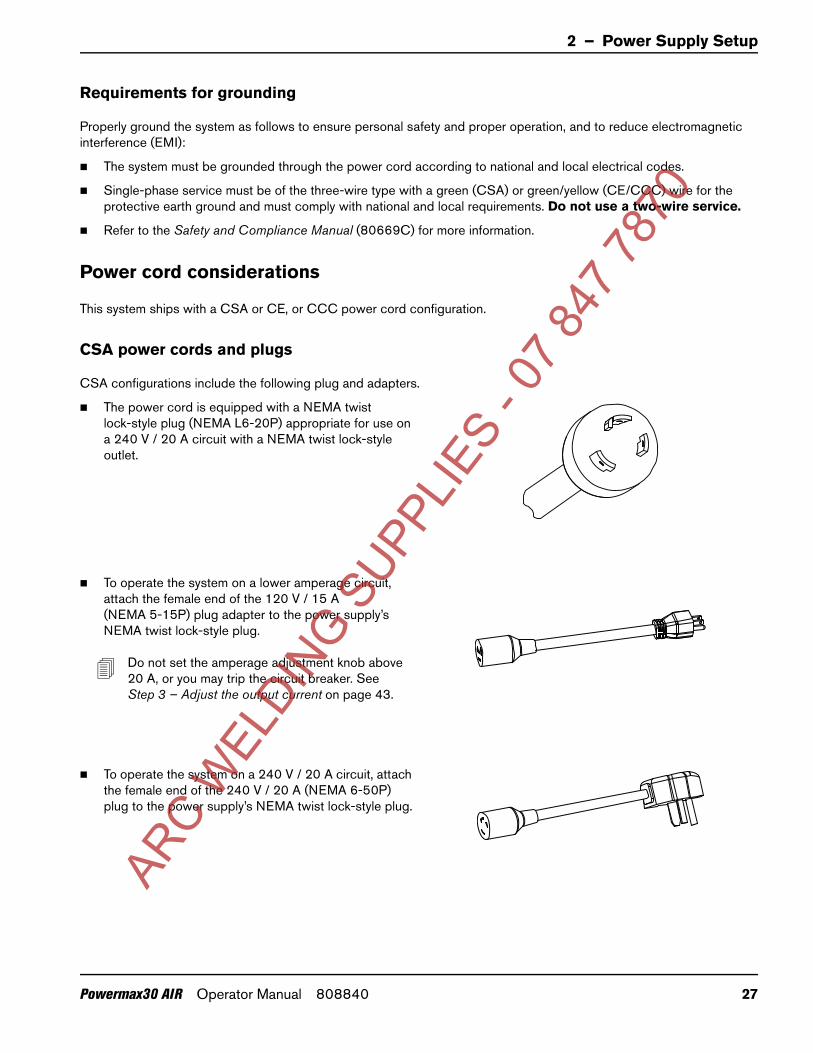
CSA power cords and plugs
CSA configurations include the following plug and adapters.
The power cord is equipped with a NEMA twist lock-style plug (NEMA L6-20P) appropriate for use on a 240 V / 20 A circuit with a NEMA twist lock-style outlet.
To operate the system on a lower amperage circuit, attach the female end of the 120 V / 15 A (NEMA 5-15P) plug adapter to the power supply’s NEMA twist lock-style plug.
Do not set the amperage adjustment knob above 20 A, or you may trip the circuit breaker. See Step 3 – Adjust the output current on page 43.
To operate the system on a 240 V / 20 A circuit, attach the female end of the 240 V / 20 A (NEMA 6-50P) plug to the power supply’s NEMA twist lock-style plug.
ARC W
ELDIN
G SUPP
LIES
- 07 8
47 78
70
Powermax30 AIR Operator Manual 808840 27
2 – Power Supply Setup
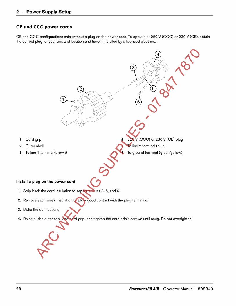
CE and CCC power cords
CE and CCC configurations ship without a plug on the power cord. To operate at 220 V (CCC) or 230 V (CE), obtain the correct plug for your unit and location and have it installed by a licensed electrician.
Install a plug on the power cord
1. Strip back the cord insulation to separate wires 3, 5, and 6.
2. Remove each wire’s insulation to allow good contact with the plug terminals.
3. Make the connections.
4. Reinstall the outer shell and cord grip, and tighten the cord grip’s screws until snug. Do not overtighten.
1
2
3
4
5
6
1 Cord grip
2 Outer shell
3 To line 1 terminal (brown)
4 220 V (CCC) or 230 V (CE) plug
5 To line 2 terminal (blue)
6 To ground terminal (green/yellow)
ARC W
ELDIN
G SUPP
LIES
- 07 8
47 78
70
28 Powermax30 AIR Operator Manual 808840
2 – Power Supply Setup
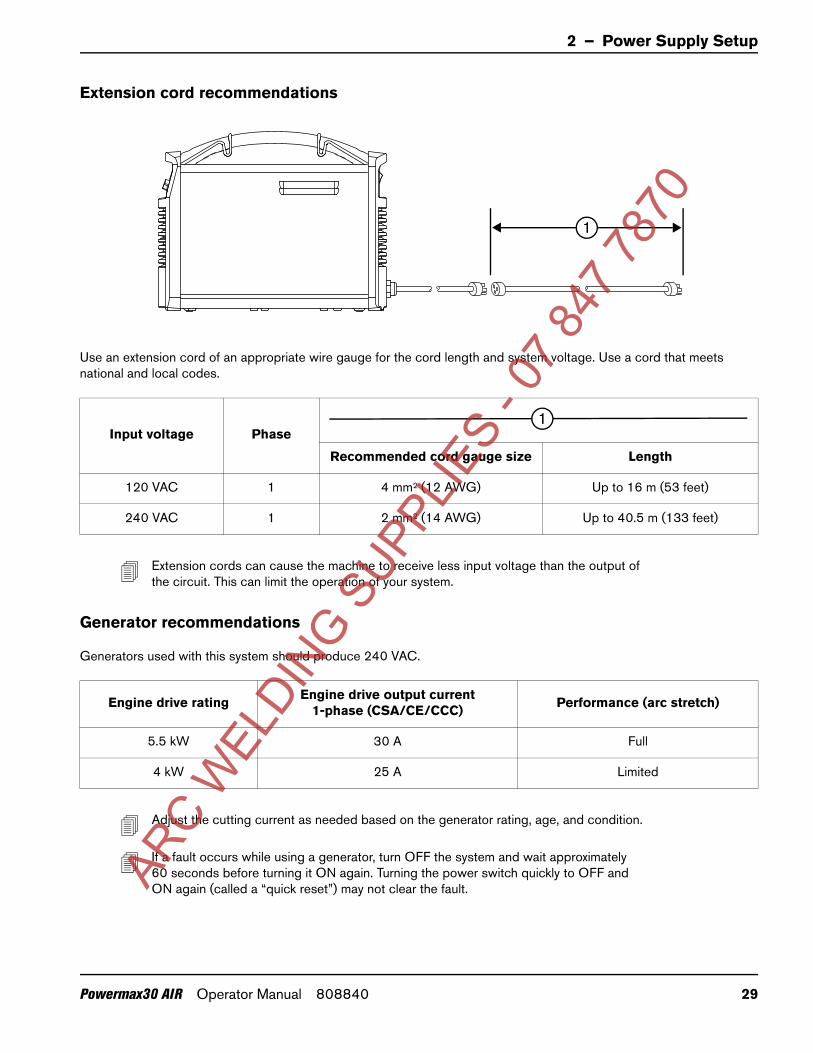
Extension cord recommendations
Use an extension cord of an appropriate wire gauge for the cord length and system voltage. Use a cord that meets national and local codes.
Extension cords can cause the machine to receive less input voltage than the output of the circuit. This can limit the operation of your system.
Generator recommendations
Generators used with this system should produce 240 VAC.
Adjust the cutting current as needed based on the generator rating, age, and condition.
If a fault occurs while using a generator, turn OFF the system and wait approximately 60 seconds before turning it ON again. Turning the power switch quickly to OFF and ON again (called a “quick reset”) may not clear the fault.
Input voltage Phase
Recommended cord gauge size Length
120 VAC 1 4 mm2 (12 AWG) Up to 16 m (53 feet)
240 VAC 1 2 mm2 (14 AWG) Up to 40.5 m (133 feet)
Engine drive rating Engine drive output current1-phase (CSA/CE/CCC) Performance (arc stretch)
5.5 kW 30 A Full
4 kW 25 A Limited
1
1
ARC W
ELDIN
G SUPP
LIES
- 07 8
47 78
70
Powermax30 AIR Operator Manual 808840 29

2 – Power Supply Setup
ARC W
ELDIN
G SUPP
LIES
- 07 8
47 78
70
30 Powermax30 AIR Operator Manual 808840
70
Section 3
Torch Setup
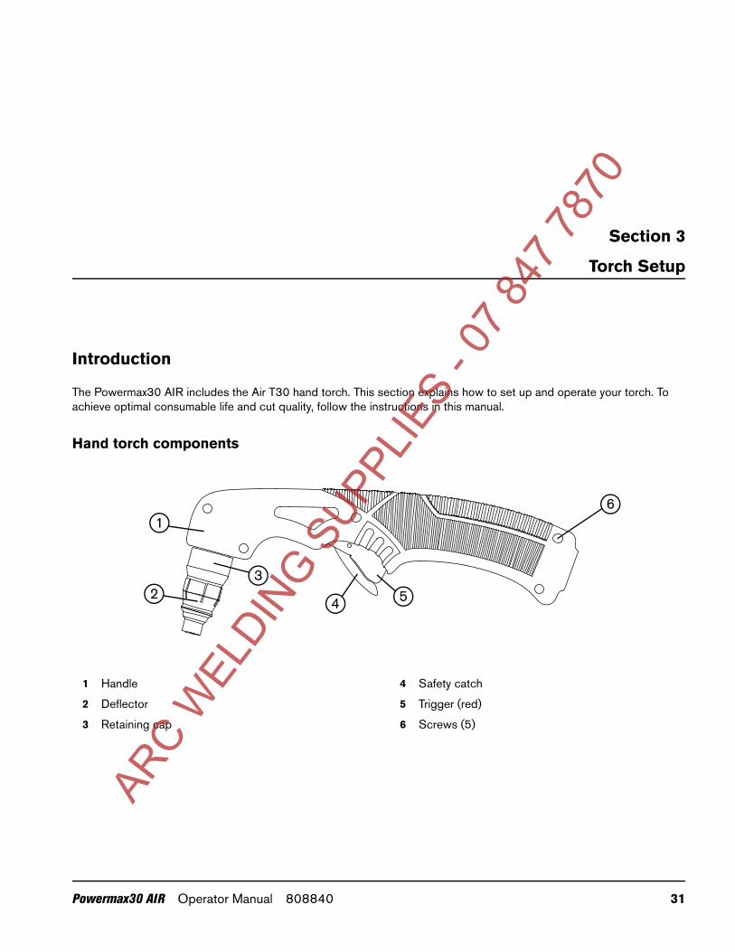
Introduction
The Powermax30 AIR includes the Air T30 hand torch. This section explains how to set up and operate your torch. To achieve optimal consumable life and cut quality, follow the instructions in this manual.
Hand torch components
1
23
4 5
6
1 Handle
2 Deflector
3 Retaining cap
4 Safety catch
5 Trigger (red)
6 Screws (5)
ARC W
ELDIN
G SUPP
LIES
- 07 8
47 78
Powermax30 AIR Operator Manual 808840 31

3 – Torch Setup
Consumable life
Consumable life varies based on the following factors:
Thickness of the metal.
Length of the average cut.
Type of cutting (piercing decreases life when compared to edge cutting).
Pierce height (stretching the arc).
Whether you are cutting solid metal or expanded metal. Cutting expanded metal wears out consumables more quickly. For more information, see Cutting expanded metal on page 43.
Hypertherm does not recommend the use of any other consumables in the Air T30 torch except for those listed in this section, which are designed specifically for this system. The use of any other consumables could adversely affect system performance.
Although largely dependent on the factors listed above, as a general rule, the consumables last approximately 1 to 2 hours of actual “arc on” time. See Inspect the consumables on page 55 for information on the signs of wear to look for in consumables.
If the consumables’ life is shorter than expected or the cut quality is poor, make sure that you are using the correct consumables and that they are properly installed. (See the following topic, Consumable use.) Under normal conditions, the nozzle wears out first.
For optimal cutting performance, always replace the nozzle and the electrode together.
See Hand torch operation on page 48 for more information about proper cutting techniques.
ARC W
ELDIN
G SUPP
LIES
- 07 8
47 78
70
32 Powermax30 AIR Operator Manual 808840
3 – Torch Setup
Consumable use
The hand torch ships with a complete set of consumables installed. The consumables are designed for a broad range of cutting applications.
The amperage output setting you need to use depends on the thickness of the metal you are planning to cut and is limited by the input power to your system. See Voltage configurations on page 25.
Do not use any other consumables in the Air T30 torch except for those listed in this section, which are designed specifically for this system. The use of any other consumables could adversely affect system performance.
Using the cut charts
Use the following cut charts to guide you in selecting the cutting current (amperage) based on the thickness and type of the metal you need to cut.
The maximum cut speeds listed in the cut charts are the fastest possible speeds to cut metal without regard to cut quality. Adjust the cutting speed for your application to obtain the desired cut quality.
WARNING!INSTANT-ON TORCHES
PLASMA ARC CAN CAUSE INJURY AND BURNS
The plasma arc ignites immediately when you pull the torch trigger. Make sure the power is OFF before changing consumables.
I
O
ARC W
ELDIN
G SUPP
LIES
- 07 8
47 78
70
Powermax30 AIR Operator Manual 808840 33
3 – Torch Setup
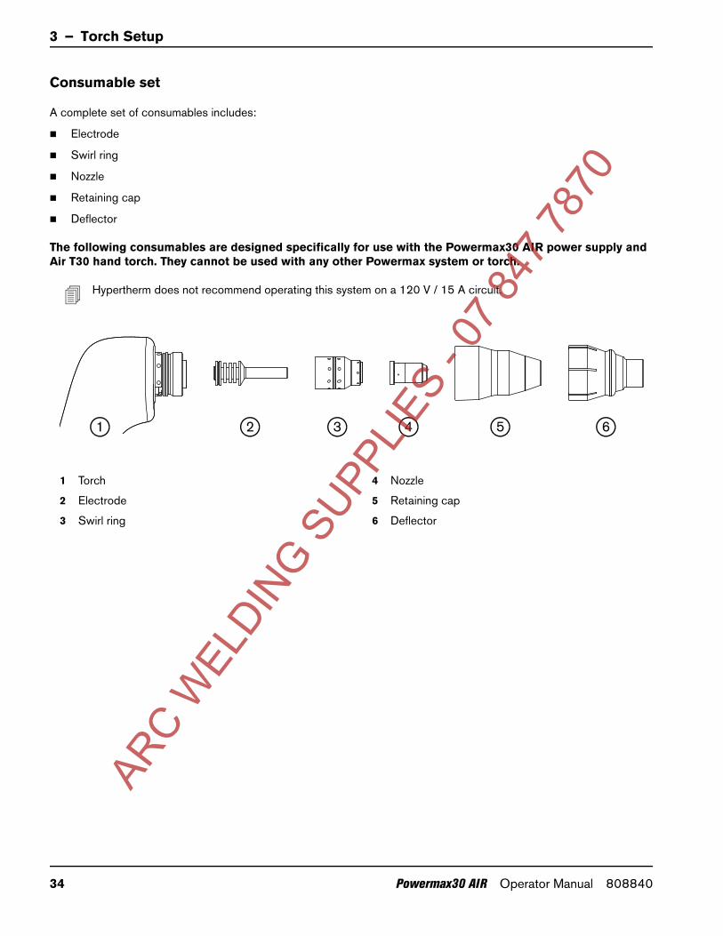
Consumable set
A complete set of consumables includes:
Electrode
Swirl ring
Nozzle
Retaining cap
Deflector
The following consumables are designed specifically for use with the Powermax30 AIR power supply and Air T30 hand torch. They cannot be used with any other Powermax system or torch.
Hypertherm does not recommend operating this system on a 120 V / 15 A circuit.
54321 6
1 Torch
2 Electrode
3 Swirl ring
4 Nozzle
5 Retaining cap
6 Deflector
ARC W
ELDIN
G SUPP
LIES
- 07 8
47 78
70
34 Powermax30 AIR Operator Manual 808840
3 – Torch Setup
240 V / 30 A cutting
Metric
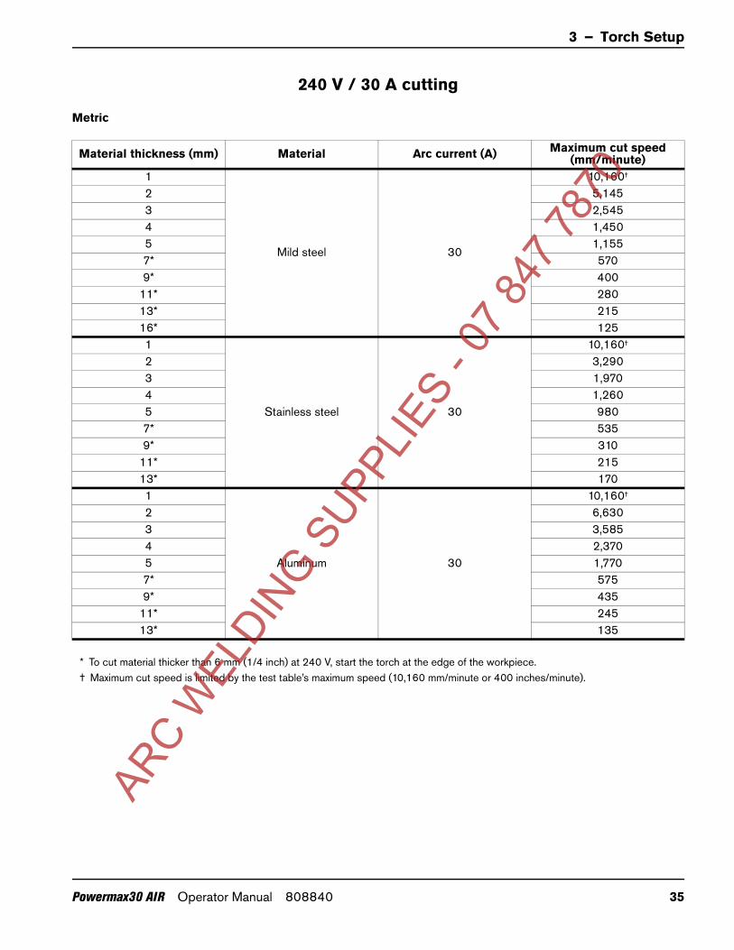
Material thickness (mm) Material Arc current (A) Maximum cut speed (mm/minute)
1
Mild steel 30
10,160†
2 5,1453 2,5454 1,4505 1,1557* 5709* 400
11* 28013* 21516* 1251
Stainless steel 30
10,160†
2 3,2903 1,9704 1,2605 9807* 5359* 310
11* 21513* 1701
Aluminum 30
10,160†
2 6,6303 3,5854 2,3705 1,7707* 5759* 435
11* 24513* 135
* To cut material thicker than 6 mm (1/4 inch) at 240 V, start the torch at the edge of the workpiece.† Maximum cut speed is limited by the test table’s maximum speed (10,160 mm/minute or 400 inches/minute).
ARC W
ELDIN
G SUPP
LIES
- 07 8
47 78
70
Powermax30 AIR Operator Manual 808840 35

3 – Torch Setup
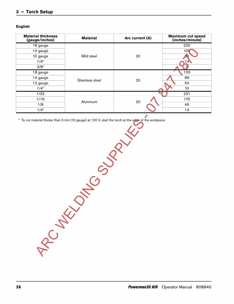
English
Material thickness (gauge/inches) Material Arc current (A) Maximum cut speed
(inches/minute)18 gauge
Mild steel 30
39514 gauge 21412 gauge 13010 gauge 64
1/4 305/16* 223/8* 131/2* 95/8* 5
18 gauge
Stainless steel 30
37014 gauge 13510 gauge 56
1/4 243/8* 101/2* 71/32
Aluminum 30
400†
1/16 3061/8 1111/4 383/8* 131/2* 6
* To cut material thicker than 6 mm (1/4 inch) at 240 V, start the torch at the edge of the workpiece.† Maximum cut speed is limited by the test table’s maximum speed (10,160 mm/minute or 400 inches/minute).
ARC W
ELDIN
G SUPP
LIES
- 07 8
47 78
70
36 Powermax30 AIR Operator Manual 808840
3 – Torch Setup
120 V / 20 A cutting
Metric
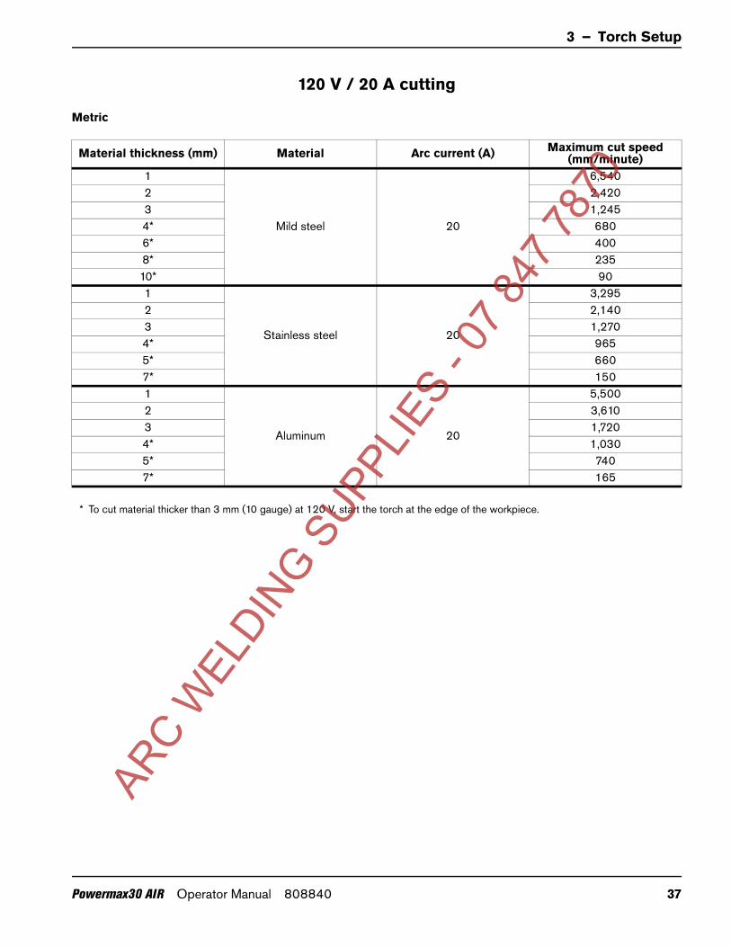
Material thickness (mm) Material Arc current (A) Maximum cut speed (mm/minute)
1
Mild steel 20
6,5402 2,4203 1,2454* 6806* 4008* 23510* 901
Stainless steel 20
3,2952 2,1403 1,2704* 9655* 6607* 1501
Aluminum 20
5,5002 3,6103 1,7204* 1,0305* 7407* 165
* To cut material thicker than 3 mm (10 gauge) at 120 V, start the torch at the edge of the workpiece.
ARC W
ELDIN
G SUPP
LIES
- 07 8
47 78
70
Powermax30 AIR Operator Manual 808840 37
3 – Torch Setup
English
Material thickness (gauge/inches) Material Arc current (A) Maximum cut speed
(inches/minute)18 gauge
Mild steel 20
22014 gauge 10010 gauge 30
1/4* 143/8* 5
18 gauge
Stainless steel 20
12014 gauge 8912 gauge 54
1/4* 101/32
Aluminum 20
2311/16 1701/8 491/4* 14
* To cut material thicker than 3 mm (10 gauge) at 120 V, start the torch at the edge of the workpiece.
ARC W
ELDIN
G SUPP
LIES
- 07 8
47 78
70
38 Powermax30 AIR Operator Manual 808840
70
Section 4
Operation
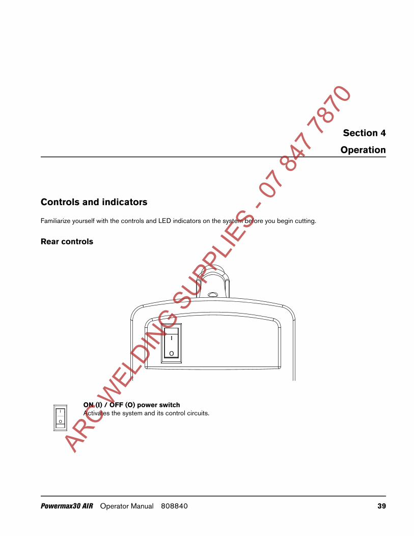
Controls and indicators
Familiarize yourself with the controls and LED indicators on the system before you begin cutting.
Rear controls
ON (I) / OFF (O) power switchActivates the system and its control circuits.
O
O
ARC W
ELDIN
G SUPP
LIES
- 07 8
47 78
Powermax30 AIR Operator Manual 808840 39
4 – Operation
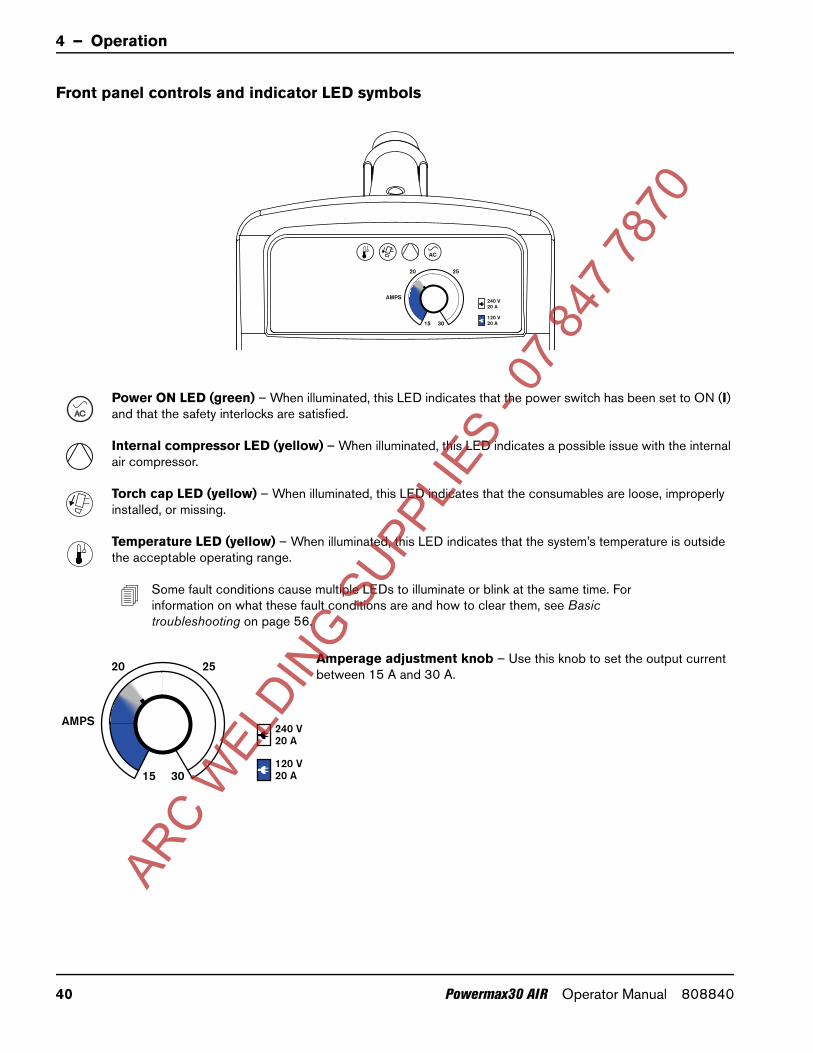
Front panel controls and indicator LED symbols
Power ON LED (green) – When illuminated, this LED indicates that the power switch has been set to ON (I) and that the safety interlocks are satisfied.
Internal compressor LED (yellow) – When illuminated, this LED indicates a possible issue with the internal air compressor.
Torch cap LED (yellow) – When illuminated, this LED indicates that the consumables are loose, improperly installed, or missing.
Temperature LED (yellow) – When illuminated, this LED indicates that the system’s temperature is outside the acceptable operating range.
Some fault conditions cause multiple LEDs to illuminate or blink at the same time. For information on what these fault conditions are and how to clear them, see Basic troubleshooting on page 56.
Amperage adjustment knob – Use this knob to set the output current between 15 A and 30 A.
AC
ARC W
ELDIN
G SUPP
LIES
- 07 8
47 78
70
40 Powermax30 AIR Operator Manual 808840

4 – Operation
Operate the plasma system
The following topics explain how to begin cutting with the plasma system.
Step 1 – Install the consumables
Before operating the plasma system and hand torch, first make sure:
1. The power switch on the power supply is in the OFF (O) position.
2. A complete set of consumables is installed on the hand torch as shown:
Electrode
Swirl ring
Nozzle
Retaining cap
Deflector*
* Install the deflector by snapping it securely into place on the retaining cap.
Do not apply grease or other lubricants to the O-rings on the electrode and swirl ring.
These consumables are designed specifically for the Powermax30 AIR power supply and Air T30 hand torch. They cannot be used with any other Powermax system or torch.
WARNING!INSTANT-ON TORCHES
PLASMA ARC CAN CAUSE INJURY AND BURNS
The plasma arc ignites immediately when you pull the torch trigger. Make sure the power is OFF (O) before changing consumables.
I
O
Tighten only to finger tight.
1
2
3
4
5
1
2
3
4
5
ARC W
ELDIN
G SUPP
LIES
- 07 8
47 78
70
Powermax30 AIR Operator Manual 808840 41

4 – Operation
Step 2 – Connect the electrical power
Plug in the power cord.
See also
For information on connecting the proper plug to the power cord, see Power cord considerations on page 27.
To understand what cutting capacity to expect based on input voltage, see Consumable use on page 33.
For information on electrical requirements for this system, see Power Supply Setup on page 23.
ARC W
ELDIN
G SUPP
LIES
- 07 8
47 78
70
42 Powermax30 AIR Operator Manual 808840
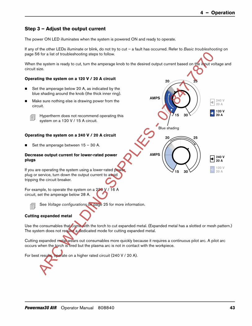
4 – Operation
Step 3 – Adjust the output current
The power ON LED illuminates when the system is powered ON and ready to operate.
If any of the other LEDs illuminate or blink, do not try to cut – a fault has occurred. Refer to Basic troubleshooting on page 56 for a list of troubleshooting steps to follow.
When the system is ready to cut, turn the amperage knob to the desired output current based on the input voltage and circuit size.
Operating the system on a 120 V / 20 A circuit
Set the amperage below 20 A, as indicated by the blue shading around the knob (the thick inner ring).
Make sure nothing else is drawing power from the circuit.
Hypertherm does not recommend operating this system on a 120 V / 15 A circuit.
Operating the system on a 240 V / 20 A circuit
Set the amperage between 15 – 30 A.
Decrease output current for lower-rated power plugs
If you are operating the system using a lower-rated power plug or service, turn down the output current to avoid tripping the circuit breaker.
For example, to operate the system on a 230 V / 16 A circuit, set the amperage below 28 A.
See Voltage configurations on page 25 for more information.
Cutting expanded metal
Use the consumables that come with the torch to cut expanded metal. (Expanded metal has a slotted or mesh pattern.) The system does not require a dedicated mode for cutting expanded metal.
Cutting expanded metal wears out consumables more quickly because it requires a continuous pilot arc. A pilot arc occurs when the torch is fired but the plasma arc is not in contact with the workpiece.
For best results, operate on a higher rated circuit (240 V / 20 A).
Blue shading
ARC W
ELDIN
G SUPP
LIES
- 07 8
47 78
70
Powermax30 AIR Operator Manual 808840 43
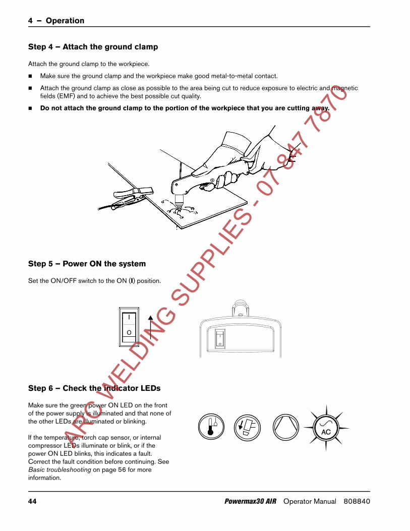
4 – Operation
Step 4 – Attach the ground clamp
Attach the ground clamp to the workpiece.
Make sure the ground clamp and the workpiece make good metal-to-metal contact.
Attach the ground clamp as close as possible to the area being cut to reduce exposure to electric and magnetic fields (EMF) and to achieve the best possible cut quality.
Do not attach the ground clamp to the portion of the workpiece that you are cutting away.
Step 5 – Power ON the system
Set the ON/OFF switch to the ON (I) position.
Step 6 – Check the indicator LEDs
Make sure the green power ON LED on the front of the power supply is illuminated and that none of the other LEDs are illuminated or blinking.
If the temperature, torch cap sensor, or internal compressor LEDs illuminate or blink, or if the power ON LED blinks, this indicates a fault. Correct the fault condition before continuing. See Basic troubleshooting on page 56 for more information.
O
O
ARC W
ELDIN
G SUPP
LIES
- 07 8
47 78
70
44 Powermax30 AIR Operator Manual 808840
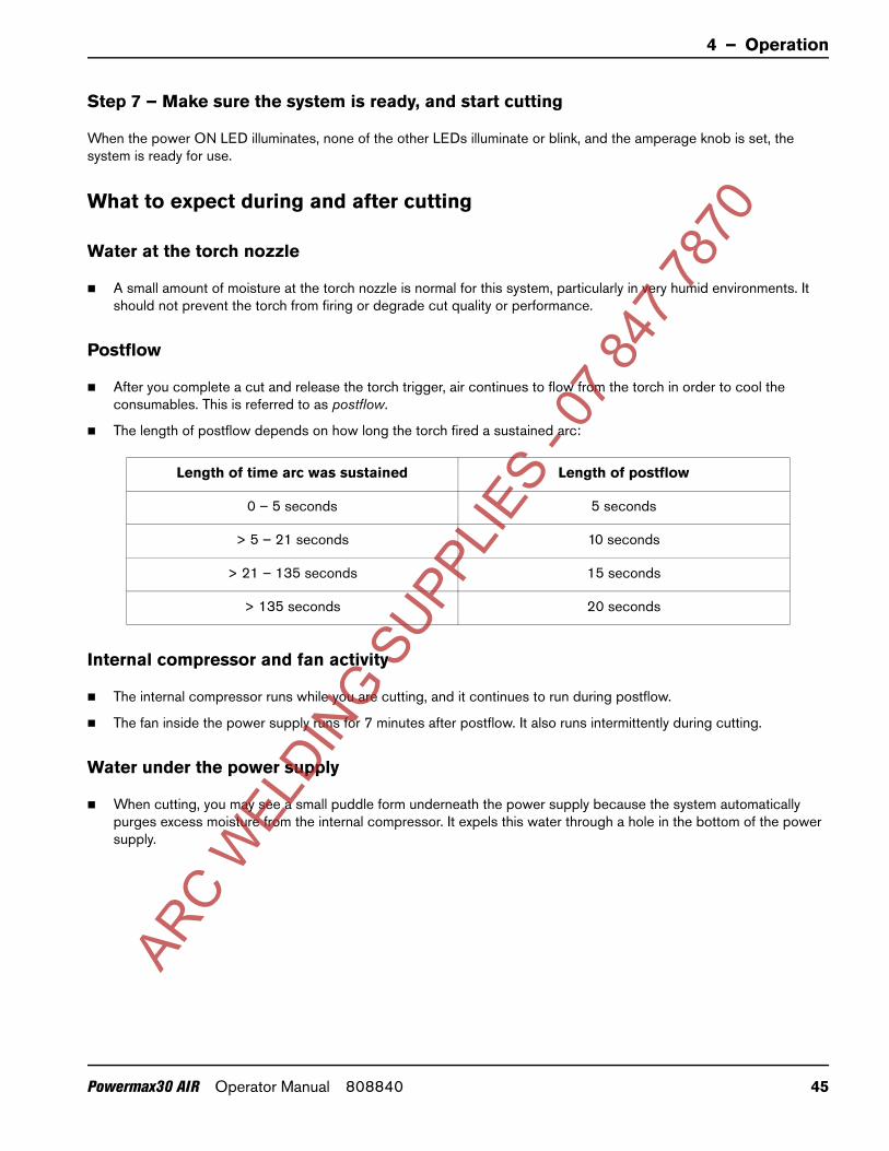
4 – Operation
Step 7 – Make sure the system is ready, and start cutting
When the power ON LED illuminates, none of the other LEDs illuminate or blink, and the amperage knob is set, the system is ready for use.
What to expect during and after cutting
Water at the torch nozzle
A small amount of moisture at the torch nozzle is normal for this system, particularly in very humid environments. It should not prevent the torch from firing or degrade cut quality or performance.
Postflow
After you complete a cut and release the torch trigger, air continues to flow from the torch in order to cool the consumables. This is referred to as postflow.
The length of postflow depends on how long the torch fired a sustained arc:
Internal compressor and fan activity
The internal compressor runs while you are cutting, and it continues to run during postflow.
The fan inside the power supply runs for 7 minutes after postflow. It also runs intermittently during cutting.
Water under the power supply
When cutting, you may see a small puddle form underneath the power supply because the system automatically purges excess moisture from the internal compressor. It expels this water through a hole in the bottom of the power supply.
Length of time arc was sustained Length of postflow
0 – 5 seconds 5 seconds
> 5 – 21 seconds 10 seconds
> 21 – 135 seconds 15 seconds
> 135 seconds 20 seconds
ARC W
ELDIN
G SUPP
LIES
- 07 8
47 78
70
Powermax30 AIR Operator Manual 808840 45

4 – Operation
Understand duty-cycle limitations
The duty cycle is the percentage of time out of 10 minutes that a plasma arc can remain on when operating at an ambient temperature of 40°C (104°F).
35% duty cycle at 240 V / 30 A: With input power of 240 V and the output current set to 30 A, the arc can remain on for 3.5 minutes out of 10 minutes without causing the unit to overheat.
20% duty cycle at 120 V / 30 A*: With input power of 120 V and the output current set to 30 A, the arc can remain on for 2.0 minutes out of 10 minutes without causing the unit to overheat.
* Although the duty cycle is rated for 30 A output, the recommended output current for 120 V circuits is 20 A or less. Operating the system at 30 A on 120 V input can result in frequent tripped circuit breakers.
When you exceed the duty cycle and the system overheats, one of the following conditions occurs:
The temperature LED illuminates, the arc shuts off, and the cooling fan continues to run. To resume cutting, wait for the temperature LED to extinguish.
The internal compressor LED and the temperature LED both illuminate. Allow the power supply to cool for 4 minutes before using it again. If the problem persists, see Internal compressor LED faults on page 58 for more troubleshooting tips.
When either condition occurs, leave the system on to allow the fan to cool the power supply. The fan runs for 7 minutes after postflow.
Stretching the arc for prolonged periods while cutting can reduce the duty cycle. Stretching the arc requires the power supply to generate a higher voltage output, which can cause it to run hotter and overheat more quickly.
ARC W
ELDIN
G SUPP
LIES
- 07 8
47 78
70
46 Powermax30 AIR Operator Manual 808840

4 – Operation
System operation guidelines
To achieve the highest level of performance:
Operate the system at an input power of 240 VAC whenever possible.
Do not operate the system on a 120 V / 15 A circuit.
Avoid using an extension cord whenever possible.
If you must use an extension cord, use a heavy conductor cord of the shortest possible length. See Extension cord recommendations on page 29.
If you are operating your system on a 120 V / 20 A circuit, do not set the amperage higher than 20 A. See Voltage configurations on page 25.
For best results when operating your system on a 120 V / 20 A circuit:
Do not connect anything else that will draw power from the same circuit.
Be aware that extension cords can reduce the voltage to the machine from what is output by the circuit. This reduction in power can impair cutting performance and increase the probability of tripping the circuit breaker.
Cutting a thicker workpiece requires a higher amperage setting. It is preferable to operate on a higher rated circuit (240 V / 30 A) when cutting thicker metal. See Voltage configurations on page 25.
Additional techniques to reduce the frequency of tripped circuit breakers include:
Turn down the amperage adjustment knob.
Avoid stretching the arc. Instead, drag the torch on the workpiece as explained in Edge start on a workpiece on page 50.
When you operate the system at altitudes higher than 2,200 m (7,500 feet) above sea level, you may experience some reduction in cutting performance due to the adverse effect that altitude has on the internal air compressor.
ARC W
ELDIN
G SUPP
LIES
- 07 8
47 78
70
Powermax30 AIR Operator Manual 808840 47

4 – Operation
Hand torch operation
Safety catch operation
The torch is equipped with a safety catch to prevent accidental firings. When you are ready to cut with the torch, flip the safety catch forward (toward the torch head) and pull the red torch trigger.
WARNING!INSTANT-ON TORCHES
PLASMA ARC CAN CAUSE INJURY AND BURNS
Plasma arc ignites immediately when you pull the torch trigger. The plasma arc cuts quickly through gloves and skin.
Keep hands, clothes, and objects away from the torch tip.
Do not hold the workpiece, and keep your hands clear of the cutting path.
Never point the torch toward yourself or others.
WARNING!SPARKS AND HOT METAL
CAN INJURE EYES AND BURN SKIN
Always wear proper protective equipment including gloves and eye protection, and point the torch away from yourself and others. Sparks and hot molten metal spray out from the nozzle.
1
2
3ARC W
ELDIN
G SUPP
LIES
- 07 8
47 78
70
48 Powermax30 AIR Operator Manual 808840

4 – Operation
Hand torch cutting guidelines
Drag the torch tip lightly on the workpiece to maintain a steady cut speed.
With drag-cutting, it is normal to experience the torch sticking slightly to the workpiece.
While cutting, make sure that sparks exit from the bottom of the workpiece. The sparks should lag slightly behind the torch as you cut (15° – 30° angle from vertical).
If sparks spray up, you are not cutting all the way through the workpiece. Move the torch more slowly, or, if possible, increase the output current.
Hold the torch nozzle perpendicular to the workpiece so that the nozzle is at a 90° angle to the cutting surface, and watch the arc as it cuts along the line.
Pulling the torch toward you along the cut is easier than pushing it or moving from side-to-side.
For straight-line cuts, use a straight edge as a guide. To cut circles, use a template or a radius cutter attachment (a circle cutting guide). See Accessory parts on page 67 for the Hypertherm plasma cutting guide part numbers for cutting circles and making bevel cuts.
If you fire the torch unnecessarily, you shorten the life of the nozzle and electrode.
Recommendations for cutting at 120 V
Do not operate the system on a 15 A circuit.
Do not use an extension cord.
Make sure nothing else is drawing power from the circuit.
Turn down the current adjustment knob to avoid tripping the breaker.
ARC W
ELDIN
G SUPP
LIES
- 07 8
47 78
70
Powermax30 AIR Operator Manual 808840 49

4 – Operation
Edge start on a workpiece
When cutting material up to 10 mm (3/8 inch) thick, start the torch at the edge of the workpiece to prolong consumable life.
1. With the ground clamp attached to the workpiece, hold the torch perpendicular (90°) to the workpiece and on the edge.
2. Pull the torch trigger to start the arc. You may need to pause at the edge until the arc has cut completely through the workpiece.
3. Drag the torch lightly across the workpiece to proceed with the cut. Maintain a steady, even pace.
ARC W
ELDIN
G SUPP
LIES
- 07 8
47 78
70
50 Powermax30 AIR Operator Manual 808840
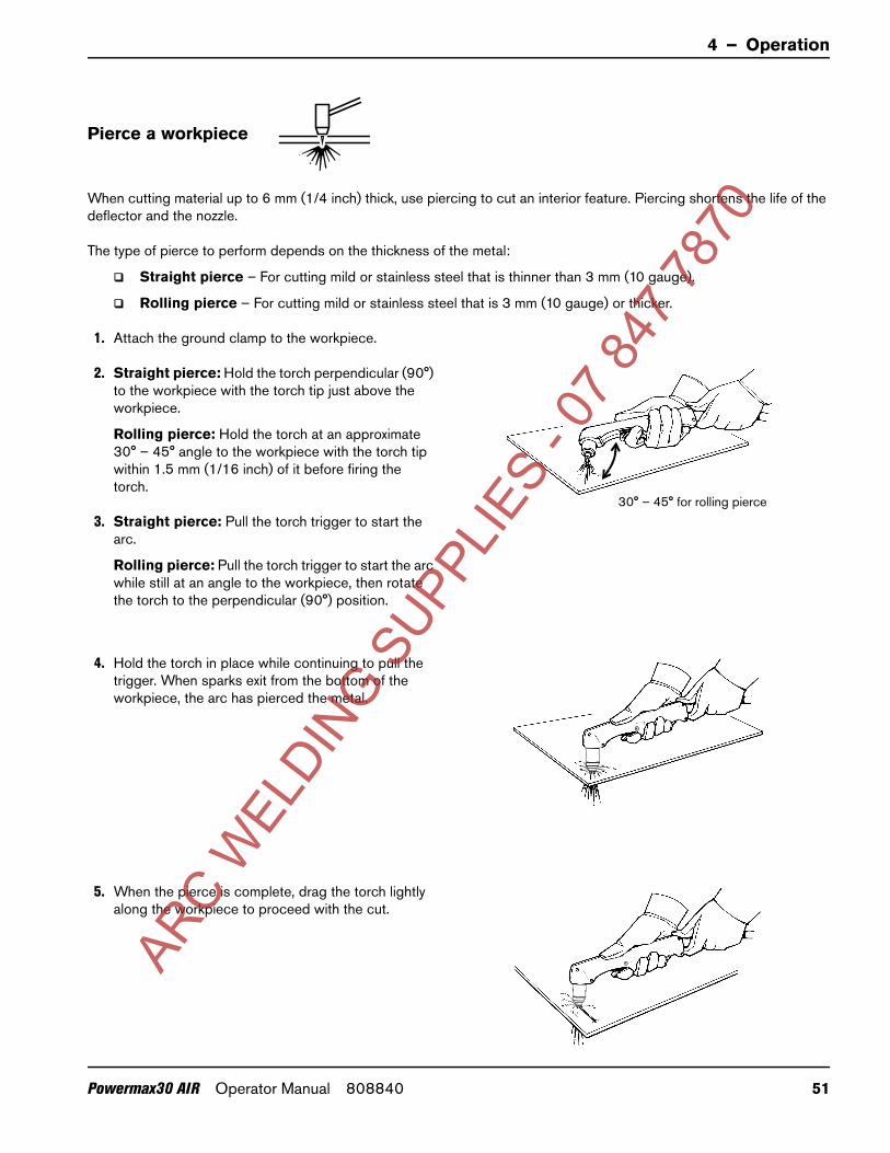
4 – Operation
Pierce a workpiece
When cutting material up to 6 mm (1/4 inch) thick, use piercing to cut an interior feature. Piercing shortens the life of the deflector and the nozzle.
The type of pierce to perform depends on the thickness of the metal:
Straight pierce – For cutting mild or stainless steel that is thinner than 3 mm (10 gauge).
Rolling pierce – For cutting mild or stainless steel that is 3 mm (10 gauge) or thicker.
1. Attach the ground clamp to the workpiece.
2. Straight pierce: Hold the torch perpendicular (90°) to the workpiece with the torch tip just above the workpiece.
Rolling pierce: Hold the torch at an approximate 30° – 45° angle to the workpiece with the torch tip within 1.5 mm (1/16 inch) of it before firing the torch.
3. Straight pierce: Pull the torch trigger to start the arc.
Rolling pierce: Pull the torch trigger to start the arc while still at an angle to the workpiece, then rotate the torch to the perpendicular (90°) position.
4. Hold the torch in place while continuing to pull the trigger. When sparks exit from the bottom of the workpiece, the arc has pierced the metal.
5. When the pierce is complete, drag the torch lightly along the workpiece to proceed with the cut.
30° – 45° for rolling pierce
ARC W
ELDIN
G SUPP
LIES
- 07 8
47 78
70
Powermax30 AIR Operator Manual 808840 51
4 – Operation
Common hand-cutting faults
For more information on faults, see Basic troubleshooting on page 56.
The torch sputters and hisses, but does not produce an arc. The cause can be:
Overtightened consumables
The torch does not cut completely through the workpiece. The causes can be:
Cut speed is too fast
Worn consumables
Metal being cut is too thick for the selected amperage
Installation of the wrong consumables
Poor electrical contact between the ground clamp and the workpiece
Cut quality is poor. The causes can be:
Metal being cut is too thick for the selected amperage
Installation of the wrong consumables
Cut speed is too fast or too slow
Worn or damaged consumables
The arc sputters and consumables life is shorter than expected. The causes can be:
Incorrect installation of the consumables
Installation of the wrong consumables
Moisture in the consumables or in the air supply within the system
Minimizing dross
Dross is the molten metal that solidifies on the workpiece. Some amount of dross is always present when cutting with air plasma. However, you can control the amount and type of dross by adjusting your system correctly for your application.
Low-speed dross forms when the torch’s cutting speed is too slow and the arc shoots ahead. It forms as a heavy, bubbly deposit at the bottom of the cut and is usually easy to remove. Increase your speed to reduce this type of dross.
High-speed dross forms when the cutting speed is too fast and the arc lags behind. It forms as a thin, linear bead of solid metal attached very close to the cut. It forms to the bottom of the cut and is often more difficult to remove. Decrease your speed to reduce this type of dross.
Dross is more likely to form on warm or hot metal than on cool metal. For example, the first cut in a series of cuts is likely to produce the least dross. As the workpiece heats up, more dross may form on subsequent cuts.
Worn or damaged consumables may produce intermittent dross.
ARC W
ELDIN
G SUPP
LIES
- 07 8
47 78
70
52 Powermax30 AIR Operator Manual 808840
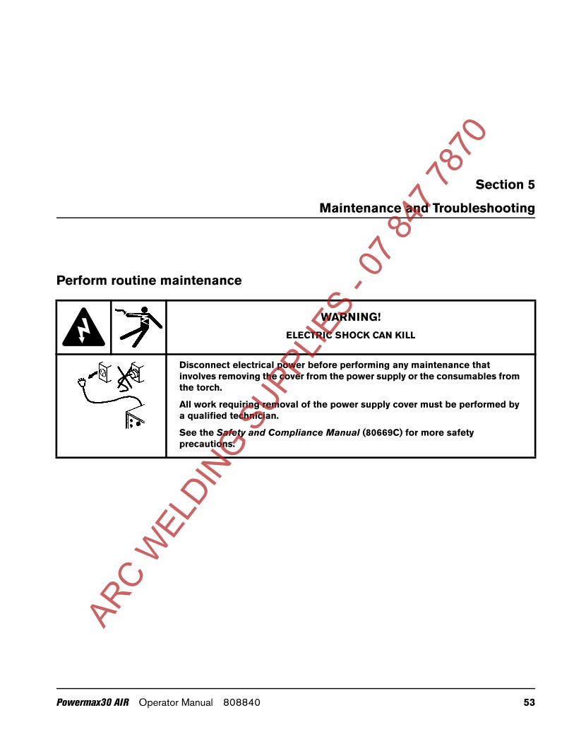
70
Section 5
Maintenance and Troubleshooting
Perform routine maintenance
WARNING!ELECTRIC SHOCK CAN KILL
Disconnect electrical power before performing any maintenance that involves removing the cover from the power supply or the consumables from the torch.
All work requiring removal of the power supply cover must be performed by a qualified technician.
See the Safety and Compliance Manual (80669C) for more safety precautions.
ARC W
ELDIN
G SUPP
LIES
- 07 8
47 78
Powermax30 AIR Operator Manual 808840 53
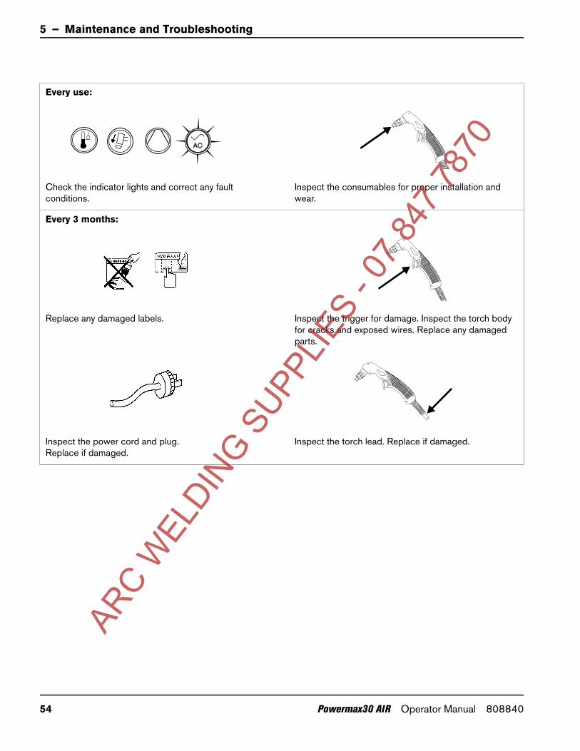
5 – Maintenance and Troubleshooting
Every use:
Check the indicator lights and correct any fault conditions.
Inspect the consumables for proper installation and wear.
Every 3 months:
Replace any damaged labels. Inspect the trigger for damage. Inspect the torch body for cracks and exposed wires. Replace any damaged parts.
Inspect the power cord and plug. Replace if damaged.
Inspect the torch lead. Replace if damaged.
ARC W
ELDIN
G SUPP
LIES
- 07 8
47 78
70
54 Powermax30 AIR Operator Manual 808840

5 – Maintenance and Troubleshooting
Inspect the consumables
Part Inspect Action
Deflector
The center hole for roundness.The rounded edges of the center hole for damage or noticeable wear.
Replace the deflector if the hole is no longer round or if it is worn or damaged.
The gap between the nozzle and the deflector for accumulated debris.
Remove the deflector and clean any material away.
Nozzle
The center hole for roundness. Replace if the center hole is not round. Replace the nozzle and the electrode together.
Electrode
The center surface for wear and verify the pit depth.
Replace if the surface is severely worn or the pit depth is greater than 1.6 mm (1/16 inch) deep. Replace the nozzle and the electrode together.Do not apply grease or other lubricants to the O-ring on the electrode.
Swirl ring
The internal surface for damage or wear and the gas holes for blockages.
Replace if the surface is damaged or worn or any of the gas holes are blocked.Do not apply grease or other lubricants to the O-ring on the swirl ring.
The length of the swirl ring. If the length of the swirl ring is less than 21 mm (0.83 inches), replace it.
Torch O-ring
The surface for damage, wear, or a lack of lubrication.
If the torch O-ring is dry, apply a thin film of silicone lubricant on the O-ring and the threads. The O-ring should look shiny, but there should not be any excess or built-up lubricant.If the O-ring is cracked or worn, replace it.
Good Worn
O-ring
Maximum 1.6 mm (1/16 inch)
O-ring
ARC W
ELDIN
G SUPP
LIES
- 07 8
47 78
70
Powermax30 AIR Operator Manual 808840 55

5 – Maintenance and Troubleshooting
Basic troubleshooting
The following sections provide an overview of the most common problems that may arise when using this system and explains how to solve them.
If you are unable to fix the problem by following this basic troubleshooting guide or if you need further assistance:
1. Call your Hypertherm distributor or authorized Hypertherm repair facility.
2. Call the nearest Hypertherm office listed in the front of this manual.
Power LED faults
The ON/OFF power switch is set to ON (I), but the power ON LED does not illuminate.
Make sure the power cord is plugged into the receptacle.
Make sure the power is on at the main power panel or at the disconnect-power switch box.
Make sure the line voltage is not too low (more than 15% below the rated voltage).
The power ON LED blinks.
Have an electrical technician check the incoming power. The input line voltage is either too high or too low (a variance greater than ±15% of the rated voltage). See Hypertherm system ratings on page 17 and Prepare the electrical power on page 25.
All four LEDs blink when the system is powered ON.
A qualified service technician must service the system. Contact your distributor or use the information in the front of this manual to contact Hypertherm Technical Service.
AC
ACO
AC
ARC W
ELDIN
G SUPP
LIES
- 07 8
47 78
70
56 Powermax30 AIR Operator Manual 808840

5 – Maintenance and Troubleshooting
Temperature LED faults
The temperature LED illuminates while the machine is powered ON.
The system overheated. Leave the system on to allow the fan to cool the power supply.
If the system’s internal temperature approaches -30°C (-22°F), the temperature LED may illuminate. Move the system to a warmer location.
The temperature LED blinks while the machine is powered ON.
Leave the system on to allow the fan to cool the power supply. The temperature LED blinks when the system continuously draws too much input current for too long. Try the following to prevent this condition:
Turn down the cutting current. See Step 3 – Adjust the output current on page 43.
Operate the system on a 240 VAC input circuit whenever possible.
Avoid stretching the arc. Drag the torch on the workpiece. See Edge start on a workpiece on page 50.
Operate the system without using an extension cord. If you must use an extension cord, use a heavy conductor cord of the shortest possible length. See Extension cord recommendations on page 29.
Make sure nothing else is drawing power on the same circuit.
ARC W
ELDIN
G SUPP
LIES
- 07 8
47 78
70
Powermax30 AIR Operator Manual 808840 57
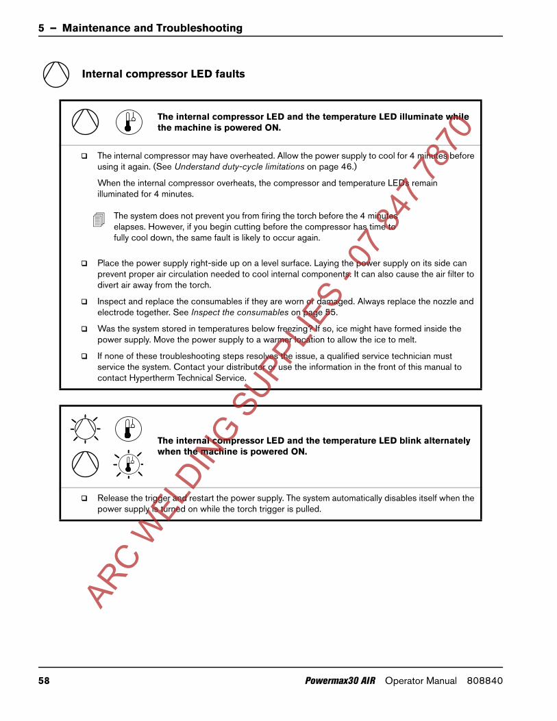
5 – Maintenance and Troubleshooting
Internal compressor LED faults
The internal compressor LED and the temperature LED illuminate while the machine is powered ON.
The internal compressor may have overheated. Allow the power supply to cool for 4 minutes before using it again. (See Understand duty-cycle limitations on page 46.)
When the internal compressor overheats, the compressor and temperature LEDs remain illuminated for 4 minutes.
The system does not prevent you from firing the torch before the 4 minutes elapses. However, if you begin cutting before the compressor has time to fully cool down, the same fault is likely to occur again.
Place the power supply right-side up on a level surface. Laying the power supply on its side can prevent proper air circulation needed to cool internal components. It can also cause the air filter to divert air away from the torch.
Inspect and replace the consumables if they are worn or damaged. Always replace the nozzle and electrode together. See Inspect the consumables on page 55.
Was the system stored in temperatures below freezing? If so, ice might have formed inside the power supply. Move the power supply to a warmer location to allow the ice to melt.
If none of these troubleshooting steps resolves the issue, a qualified service technician must service the system. Contact your distributor or use the information in the front of this manual to contact Hypertherm Technical Service.
The internal compressor LED and the temperature LED blink alternately when the machine is powered ON.
Release the trigger and restart the power supply. The system automatically disables itself when the power supply is turned on while the torch trigger is pulled.
ARC W
ELDIN
G SUPP
LIES
- 07 8
47 78
70
58 Powermax30 AIR Operator Manual 808840

5 – Maintenance and Troubleshooting
Torch LED faults
The torch cap LED illuminates or blinks while the machine is powered ON.
Inspect the torch lead. If it is twisted or kinked, straighten it out and try to fire the torch again.
Turn OFF (O) the power supply. Make sure the consumables are properly installed and tightened. See Step 1 – Install the consumables on page 41.
If the consumables became loose or were removed while the power supply was ON, turn OFF (O) the power supply, correct the problem, and then turn ON (I) the power supply to clear the fault.
If the consumables appear to be installed correctly, the torch may be damaged. Contact your Hypertherm distributor or authorized repair facility.
The internal compressor, temperature, and power ON LEDs blink, and the torch cap LED illuminates.
Install new consumables in the torch (they may be corroded or approaching end of life).
If you continue to see this error, contact your Hypertherm distributor or authorized repair facility.
AC
ARC W
ELDIN
G SUPP
LIES
- 07 8
47 78
70
Powermax30 AIR Operator Manual 808840 59

5 – Maintenance and Troubleshooting
Common cutting issues
Problem Solution
The circuit breaker trips while you are cutting.
• Turn down the cutting current. See Step 3 – Adjust the output current on page 43.
• Operate the system on a 240 VAC input circuit whenever possible.• Avoid stretching the arc. Drag the torch on the workpiece. See Edge start
on a workpiece on page 50.• Operate the system without using an extension cord. If you must use an
extension cord, use a heavy conductor cord of the shortest possible length. See Extension cord recommendations on page 29.
• Make sure nothing else is drawing power on the same circuit.
The cut quality is poor. • Make sure the torch is being used correctly. See Hand torch operation on page 48.
• Make sure the correct consumables are installed. See Consumable use on page 33.
• Inspect the consumables and replace as necessary. See Inspect the consumables on page 55.
• Loosen the consumables about 1/8th of a turn and try again.• Make sure the work lead connection is secure and there is no damage to
the work lead.• Operate the system without using an extension cord. If you must use an
extension cord, use a heavy conductor cord of the shortest possible length. See Extension cord recommendations on page 29.
The torch does not cut completely through the workpiece.
• Make sure the torch is being used correctly. See Hand torch operation on page 48.
• Inspect the consumables and replace as necessary. See Inspect the consumables on page 55.
The arc does not transfer to the workpiece.
• Clean the area where the ground clamp contacts the workpiece to ensure a good metal-to-metal contact.
• Inspect the ground clamp for damage and repair it if necessary.• Move the torch closer to the workpiece and fire the torch again. See Hand
torch operation on page 48.
ARC W
ELDIN
G SUPP
LIES
- 07 8
47 78
70
60 Powermax30 AIR Operator Manual 808840

5 – Maintenance and Troubleshooting
A small amount of moisture exits the torch nozzle.
• A small amount of moisture at the torch nozzle is normal for this system, particularly in very humid environments. It should not prevent the torch from firing or degrade cut quality or performance.
• If excess moisture exiting the torch does interfere with starting the torch or with cutting performance, contact your Hypertherm distributor or authorized repair facility.
The arc blows out but re-ignites when the torch trigger is pulled again, or the arc sputters and hisses.
• First, inspect the consumables for signs of excess moisture. A small amount of moisture at the torch nozzle is normal for this system and should not prevent the torch from firing. If excess moisture is present, fire the torch approximately 5 times in succession.
• If firing the torch does not clear out the excess moisture, and the moisture exiting the torch does interfere with starting the torch or with cutting performance, contact your Hypertherm distributor or authorized repair facility.
• If the problem persists and excess moisture is not an issue, inspect and replace the consumable parts if they are worn or damaged. See Inspect the consumables on page 55.
Problem Solution
ARC W
ELDIN
G SUPP
LIES
- 07 8
47 78
70
Powermax30 AIR Operator Manual 808840 61
5 – Maintenance and Troubleshooting
ARC W
ELDIN
G SUPP
LIES
- 07 8
47 78
70
62 Powermax30 AIR Operator Manual 808840
70
Section 6
Parts
Use the part numbers and kit numbers in this section to order consumables, accessories, and external replacement parts for your power supply and hand torch.
For instructions on installing the consumables in the hand torch, see Step 1 – Install the consumables on page 41.
This system contains no customer serviceable parts inside the power supply or inside the hand torch. For assistance with repairing or replacing internal components:
1. Call your Hypertherm distributor or authorized Hypertherm repair facility.
2. Call the nearest Hypertherm office listed in the front of this manual.
ARC W
ELDIN
G SUPP
LIES
- 07 8
47 78
Powermax30 AIR Operator Manual 808840 63

6 – Parts
Power supply parts
Exterior, front
Item Kit number Description
1 228267 Kit: Power supply handle (includes screws and shoulder strap clips)
2 428226 Kit: Current adjustment knob
3 228561 Kit: Ground clamp
1
2 3
ARC W
ELDIN
G SUPP
LIES
- 07 8
47 78
70
64 Powermax30 AIR Operator Manual 808840
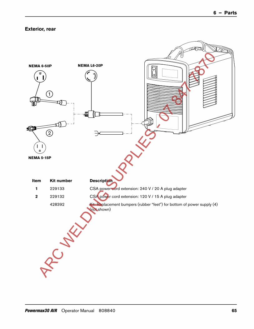
6 – Parts
Exterior, rear
Item Kit number Description
1 229133 CSA power cord extension: 240 V / 20 A plug adapter
2 229132 CSA power cord extension: 120 V / 15 A plug adapter
428392 Kit: Replacement bumpers (rubber “feet”) for bottom of power supply (4) (not shown)
1
2
NEMA 6-50P
NEMA 5-15P
NEMA L6-20P
ARC W
ELDIN
G SUPP
LIES
- 07 8
47 78
70
Powermax30 AIR Operator Manual 808840 65

6 – Parts
Hand torch consumables
To order consumables for your Air T30 torch, use the following part numbers.
You can order individual packages of nozzles and electrodes, or you can order them combined as a kit:
Use 420134 to order a package of 5 nozzles.
Use 420132 to order a package of 5 electrodes.
Use 428350 to order a kit of 2 nozzles and 2 electrodes.
These consumables are designed specifically for use with the Powermax30 AIR power supply and Air T30 hand torch. They cannot be used with any other Powermax system or torch.
Individual consumables
Kit: electrode (2) + nozzle (2)
420133420132 420134 420135
Electrode Swirl ring Nozzle Retaining cap
428179
Torch O-ring Deflector
420399
428350
ARC W
ELDIN
G SUPP
LIES
- 07 8
47 78
70
66 Powermax30 AIR Operator Manual 808840

6 – Parts
Accessory parts
Part number Description
127102 Basic plasma (circle) cutting guide
027668 Deluxe plasma (circle) cutting guide
127144 Dust cover
024548 Leather torch lead cover, brown, 7.6 m (25 feet)
024877 Leather torch lead cover, black with Hypertherm logo, 7.6 m (25 feet)
127217 Shoulder strap
127169 Leather cutting gloves
127416 Protective glasses, shade 5 lens
ARC W
ELDIN
G SUPP
LIES
- 07 8
47 78
70
Powermax30 AIR Operator Manual 808840 67

6 – Parts
Power supply labels
The label kits include:
Consumables label
Appropriate warning labels
Front and side decals
The following illustrations show the consumables label and warning labels.
Consumables label
The consumables label is affixed to the power supply’s rear panel. It shows the correct consumables to use with this system and torch and how to install them.
Kit number Description
428408 Kit: Powermax30 AIR labels, CSA
428410 Kit: Powermax30 AIR labels, CSA, Built in America
428409 Kit: Powermax30 AIR labels, CE/CCC
210347 Rev. A
420135 420134 420133 420132420399
428350
ARC W
ELDIN
G SUPP
LIES
- 07 8
47 78
70
68 Powermax30 AIR Operator Manual 808840

6 – Parts
CSA warning label
This warning label is affixed to some power supplies. It is important that the operator and maintenance technician understand the intent of these warning symbols as described.
Read and follow these instructions, employer safetypractices, and material safety data sheets. Refer to ANS Z49.1, “Safety in Welding, Cutting and Allied Processes” from American Welding Society (http://www.aws.org) and OSHA Safety and Health Standards, 29 CFR 1910 (http://www.osha.gov).
WARNING
1. Cutting sparks can cause explosion or fire.1.1 Do not cut near flammables.1.2 Have a fire extinguisher nearby and ready to use.1.3 Do not use a drum or other closed container as a cutting table.
2. Plasma arc can injure and burn; point the nozzle away from yourself. Arc starts instantly when triggered. 2.1 Turn off power before disassembling torch.2.2 Do not grip the workpiece near the cutting path.2.3 Wear complete body protection.
3. Hazardous voltage. Risk of electric shock or burn.3.1 Wear insulating gloves. Replace gloves when wet or damaged.3.2 Protect from shock by insulating yourself from work and ground.3.3 Disconnect power before servicing. Do not touch live parts.
4. Plasma fumes can be hazardous.4.1 Do not inhale fumes. 4.2 Use forced ventilation or local exhaust to remove the fumes.4.3 Do not operate in closed spaces. Remove fumes with ventilation.
6. Become trained. Only qualified personnel should operate this equipment. Use torches specified in the manual. Keep non-qualified personnel and children away.
5. Arc rays can burn eyes and injure skin.5.1 Wear correct and appropriate protective equipment to protect head, eyes, ears, hands, and body. Button shirt collar. Protect ears from noise. Use welding helmet with the correct shade of filter.
7. Do not remove, destroy, or cover this label. Replace if it is missing, damaged, or worn.
Plasma cutting can be injurious to operator and persons in the work area. Consult manual before operating. Failure to follow all these safety instructions can result in death.
(PN 110673 Rev D)
AVERTISSEMENTLe coupage plasma peut être préjudiciable pour l’opérateur et les personnes qui se trouvent sur les lieux de travail. Consulter le manuel avant de faire fonctionner. Le non respect des ces instructions de sécurité peut entraîner la mort.
1. Les étincelles de coupage peuvent provoquer une explosion ou un incendie.1.1 Ne pas couper près des matières inflammables. 1.2 Un extincteur doit être à proximité et prêt à être utilisé.1.3 Ne pas utiliser un fût ou un autre contenant fermé comme table de coupage.
2. L’arc plasma peut blesser et brûler; éloigner la buse de soi. Il s’allume instantanément quand on l’amorce. 2.1 Couper l’alimentation avant de démonter la torche. 2.2 Ne pas saisir la pièce à couper de la trajectoire de coupage. 2.3 Se protéger entièrement le corps.
3. Tension dangereuse. Risque de choc électrique ou de brûlure. 3.1 Porter des gants isolants. Remplacer les gants quand ils sont humides ou endommagés. 3.2 Se protéger contre les chocs en s’isolant de la pièce et de la terre. 3.3 Couper l’alimentation avant l’entretien. Ne pas toucher les pièces sous tension.4. Les fumées plasma peuvent être dangereuses. 4.1 Ne pas inhaler les fumées. 4.2 Utiliser une ventilation forcée ou un extracteur local pour dissiper les fumées. 4.3 Ne pas couper dans des espaces clos. Chasser les fumées par ventilation.
5. Les rayons d’arc peuvent brûler les yeux et blesser la peau. 5.1 Porter un bon équipement de protection pour se protéger la tête, les yeux, les oreilles, les mains et le corps. Boutonner le col de la chemise. Protéger les oreilles contre le bruit. Utiliser un masque de soudeur avec un filtre de nuance appropriée.
6. Suivre une formation. Seul le personnel qualifié a le droit de faire fonctionner cet équipement. Utiliser exclusivement les torches indiquées dans le manual. Le personnel non qualifié et les enfants doivent se tenir à l’écart.
7. Ne pas enlever, détruire ni couvrir cette étiquette. La remplacer si elle est absente, endommagée ou usée.
(PN 110673 Rev D)
ARC W
ELDIN
G SUPP
LIES
- 07 8
47 78
70
Powermax30 AIR Operator Manual 808840 69

6 – Parts
CE/CCC warning label
This warning label is affixed to some power supplies. It is important that the operator and maintenance technician understand the intent of these warning symbols as described. The numbered text corresponds to the numbered boxes on the label.
1. Cutting sparks can cause explosion or fire.
1.1 Do not cut near flammables.1.2 Have a fire extinguisher nearby and
ready to use.1.3 Do not use a drum or other closed
container as a cutting table.2. Plasma arc can injure and burn; point
the nozzle away from yourself. Arc starts instantly when triggered.
2.1 Turn off power before disassembling torch.
2.2 Do not grip the workpiece near the cutting path.
2.3 Wear complete body protection.3. Hazardous voltage. Risk of electric
shock or burn.3.1 Wear insulating gloves. Replace
gloves when wet or damaged.3.2 Protect from shock by insulating
yourself from work and ground.3.3 Disconnect power before servicing.
Do not touch live parts.4. Plasma fumes can be hazardous.4.1 Do not inhale fumes.4.2 Use forced ventilation or local exhaust
to remove the fumes.4.3 Do not operate in closed spaces.
Remove fumes with ventilation.5. Arc rays can burn eyes and injure
skin.5.1 Wear correct and appropriate
protective equipment to protect head, eyes, ears, hands, and body. Button shirt collar. Protect ears from noise. Use welding helmet with the correct shade of filter.
6. Become trained. Only qualified personnel should operate this equipment. Use torches specified in the manual. Keep non-qualified personnel and children away.
7. Do not remove, destroy, or cover this label. Replace if it is missing, damaged, or worn.AR
C WEL
DING S
UPPLIE
S - 0
7 847
7870
70 Powermax30 AIR Operator Manual 808840


