110
ABPL 30048 ARCHITECTURE STUDIO AIR 2015 SEMESTER 2 TUTOR: CANHUI CHEN STUDENT NAME: NING ZHU STUDENT NUMBER: 730220

ABPL 30048ARCHITECTURE STUDIO AIR2015 SEMESTER 2TUTOR: CANHUI CHENSTUDENT NAME: NING ZHUSTUDENT NUMBER: 730220


ContentsIntroduction
Part A: CONCEPTUALIZATION
A1: Design futuring
A2: Design Computation
A3: Composition & Generation
A4: Conclusion
A5: Learning Outcomes
A6: Bibliography and image references
A7: Algorithmic Sketchbook
Part B: CRITERIA DESIGN
B1: Research field
B2: Case study 1.0
B3: Case study 2.0
B4: Technique development
B5: Technique, Prototype
B6: Technique, Proposal
B7: Learning Objectives and outcomes
B8: Algorithmic Sketchbook
Part C: DETAILED DESIGN
C1: Design concept
C2: Techtonic elements & prototypes
C3: Final detail design
C4: Learning Objectives and outcomes
07
10
13
16
17
18
20
32
34
39
43
49
52
55
56
04
66
82
92
109

4 CONCEPTUALISATION
I am Ning ZHU, now it is my sixth month (August,2015) in Melbourne City, also the second semester in Bachelor of environments course at University of Melbourne, majoring in architecture.
I was born in Zhengzhou, Henan, China and raised there to finish my primary and secondary courses. After that, i went to Singapore to pursue my diploma of industrial design course at Nanyang Polytechnic for three years. After that, I worked at a project contracting company in Singapore to liaise with other teams regarding of M&E works, and costing and quantity surveying based on drawing and site conditions sometimes. It lasted almost two years. Then i resigned early this year and reached Melbourne to have my current studies.
I was rewarded 150 points to jump grade since my case is special. Since i handed in my diploma course descriptions, industrial design portfolio and some profiles on my last working experience when i applied architecture course in Unimelb, i was exempted on designing environments, visualising environemnts, environemntal building systems and all breadth courses which related to my previous courses and working experiences, that is the reason i am able to start Studio Air in my second semester.
The reason that i chose industrial design as my major during my diploma period is a bit simple. We had limited course selections in our batch from Henan Province toNanyang Polytechnic by Gaokao transcript. Excluding purely engineering courses such as electrical,mechanical ones, the only left course related to drawing as well
as engineering courses are industrial design. As for me, i do not like courses which are not related to engineering such as graphic design, digital design,etc.Since i am keep on drawing something interesting, industrial design seems my my choice.
My jumping from industrial design to architecture is complex. Firstly, my diploma in industrial design courses taught me about knowledge on aesthetic appreciation, sketching by hand and CAD, technological issues like materials, explosion views, etc, which laid the foundation of all design fields including architectural design; secondly, my job experiences allowed me to contact with varied construction participants especially architects, which pushed me to come up with an idea that i could combine my aesthetical diploma course knowledge with my technological job experiences to become an architect to lead a group of team to build a house that chopped my name; thirdly, architecture related jobs are much wider and highly-paid salary than industrial design on both China and Singapore. According to three reasons above, i would like to choose architecture as my major if i was received related oppotunities.
Studying architecture in University of Melbourne took me another special experience which is totally different with my previous ones whether studying or working, China or Singapore. I would like to adopt my experiences to be better during current learing period. Since design fields is interlinked, I hope that i could build another higher storey above my previous experiences.
INTRODUCTION
MY LOGO

CONCEPTUALISATION 5
PAST PROJECTS
Figure 1 & 2 & 3: Industrial Design Project i finished at Singapore
Figure 4 & 5: Studio earth: HERRING ISLAND, a place for keeping secret
Figure 1.
Figure 2.
Figure 3.
Figure 4. Figure 5.

PART ACONCEPTUALIZATION

A1: Design futuring
Design for futuring has to face two important issues, one is how to integrate ethics or norm with architectural practice in order to achieve sustainability purposes; the other is to solve deep level troubles in society by multiple perspectives rather than designing alone.
On the one hand, The ‘state of the world’ and the state of design need to be brought together,1 as we are currently facing with varied challenges such as environment, resources, ecological issues, etc., and deteriorations like pollutions, resource-exhausting, population explosion are threatening sustainability for our future. With technology advancing in recent decades, participants should have utilized it into design widly, however, people might either ignore its existence, or utilize its fallacious application, which leads to the results as pollution sources like light pollution, Freon leaking in contemporary cities, therefore, it is urgent to redirect design method to solve hard issues for human’s existence, which can take them from the existing momentum of a particular force and bring it to a means of change2. Meanwhile, raising design intelligence of all citizens is able to force participants to redirect design direction into the intelligence aspect
On the other hand, based on the fact that most of designs, especially buildings, are offered for mankind’s use, the thought of people-oriented should be always applied in design process. Just like Tony Fry states “Design, in the first instance, has to be understood anthropologically”3. Humans as social beings definition, varied human’s physical conditions, human’s mental feelings, human‘s variant cultures should be included in thinking scope. Meanwhile it is important that designers go beyond designing alone to think more issues on other subjects, to explore, hybridize, borrow, and embrace the many tools available for crafting not only things but also ideas—fictional worlds, cautionary tales, what-if scenarios, thought experiments,counterfactuals, reductio and absurdum experiments, prefigurative futures,4, rather than purely radical materialism or physicalism.
1 .Tony Fry, Design Futuring: Sustainability, Ethics and New Practice (Oxford: Berg, 2009), p42. Tony Fry, Design Futuring: Sustainability, Ethics and New Practice (Oxford: Berg, 2009), p113. Tony Fry, Design Futuring: Sustainability, Ethics and New Practice (Oxford: Berg, 2009), p2 4. Anthony Dunne & Fiona Raby, speculative everything,design, friction and social dreaming(publisher and time no stated),p3

8 CONCEPTUALISATION
A1: Design futuring, project 01
Fig1. Aerial view of Gardens by the bay and Conservatory complex (shell shape at left side)
Fig.2 Inside scenery of the Flower Dome
Fig.3. Inside scenery of the Cloud Forest, On top is evelope
Conservatory complex is seated at eastern zone of “Gardens by the bay”, south end of marina bay reclamation area in Singapore.The complex includes two units, the Flower Dome and the Cloud Forest(Fig.1).
This horticultural destination, as the largest controlled-climate greenhouse in the world, is to create a giant man-made climate zone for touring, experimenting, educating, etc.As Singapore is a small size but highly-populated citizens country, inland plateaus do not exist there but only surrounded by sea, so it is easily affected by sea-level rising caused by climate change.Therefore, the complex was taken advantage of passive and active sustainable technologies to create the perfect micro climate for exotic plants to grow, which accords with calling for people to care for climate change issues
The cooled conservatories achieve its own distinct climate by controlling carbon neutral status in low-energy and renewable systems. The Flower Dome(fig.2) has a cool-dryzone with a Mediterranean feel, while the Cloud Forest(fig.3) is a cool-moistbiome with a giant tropical waterfall inside. Through this method, different ranges of plants can be showed separately, thus, one of the purposes which can be defined as education is obvious(fig.4)--- the former explores interacting issues between people and plants, while the latter highlights how climate change and destruction of tropical cloud forests will threaten the Earth’s biodiversity(fig.5)
Sophisticated systems are designed to operate these greenhouses in an energy-efficient way. The envelopes(Fig.3) are the key to the whole operation; the myriad glass panels act to let in light while reducing solar heat gain. Low-e panels take in approximately 65% of the incident daylight, but only 35% of the solar heat. Cool, dry air is introduced near the bottom of the greenhouses amongst the plants and people, while hot air rises up and out of the structures or is directed back into the system for other processes, like dehumidifying. The nearby solar trees act as vents to expel hot air out and also generate hot water and electricity for the entire complex. Rainwater is collected off the greenhouses, stored and then used for irrigation. An on-site biomass boiler provides heat and electricity and is fueled entirely with green waste from the parks1.
1. Inhabitat, Gallery Singapore’s Garden By the Bay, http://inhabitat.com/singapores-gardens-by-the-bay-features-the-worlds-largest-climate-controlled-greenhouses/cooled-conservatories-wilkinson-eyre-13/?extend=1 17 Jan 2013
Fig.4. Educational purposes for Singapore local pupils
Conservatory complex (Flower Dome and the Cloud Forest), Singapore // Architect:Wilkinson Eyre
Fig.5.Diagram of highland’s biodiversity inside Cloud Forest

CONCEPTUALISATION 9
A1: Design futuring, project 02“Brick box” house, Benxi, China // Architect:Dazhong Feng
This project is located at Benxi City, Lianning Province, China, as a multi-function construction for living house, workplace studio and art gallery. Since its façade faces scenery formed by ranges of mountains(Fig.6), the main purpose of this building is to solve conflicts between social and individual, between rapid urban life and peaceful feelings in deep heart. The idea of this project is that Mr. Feng likes to construct a static and peaceful inner world first, followed by diagnosing with outer natural issues, so as to express whole potential functions for a certain building. Based on its multi-function characteristic, this building not only offers relevant tranquil space for both workplace and comfortable living, but also brings a deep-level cultural feeling through its soft power.
The house was designed as a concaved box at top surrounded by brick material(Fig.7). Slant concaved roof converge to centre, linking up three courtyards as one structure. This kind of structure reflects oriental thought, “converge all elite from whole heaven”(fig.8), which origins from southern China courtyard’s structure, “water from all directions will merge into hall pool”1.
An added timber storey was built at centre for people walking(Fig.9).Since the concaved roof shields all surrounding scenery if standing on this storey except distant mountains, sky, moon that can be viewed.This kind of structure forms a feeling of inner giant space, rather than actual space area. Viewing that scenery from limited opening, a kind of tranquil existing feeling will be felt by viewers. It is a big contrast with daytime urbanites who often lose themselves in engaged urban life,
1 weiheadline.arcticle, brick boxing house-Taolei Architect Studio, http://wtt.wzaobao.com/p/b785tE.html 17 Apr 2015
Fig6. Overall view of house, mountain background
Fig7. Concaved part at right side of image; brick material
Fig8. slant concaved roof converge to centre with courtyards
Fig9. Added timber storey at house centre

10 CONCEPTUALISATION
A2: Design computation
With the popularization of design computation, a variety of related software comes into being, such as BIM, grasshopper, etc. With the help of computation, the design process is much accelerated, jumping from freehand drawing and manual model makings, to virtual models by just inputting relevant programs and data. Therefore, workload is much relieved. Even under parametric algorithmic condition, geometries can be much changed by modifying a few data, workload is further relieved.
The practice of designers is also re-defined. As an architect, for example, before design computation comes into being, he or she has to stay at workshops filled with tools to do model-making constantly, or frequently step into construction site to check contractors whether they misunderstand design ideas; while with the help of design computation, hypostatic geometry can be modeled by machines through inputting relevant program and data, contractors also can easily understand architects’ intentions by virtual geometry, so there is no need for designers to step into workshops or sites constantly. It is the result of digital fabrication, which emerges mathematics inside design rather than previous purely design.
Another change taken by design computation is that architects can more easily participate in branch fields of whole project. With modifying programs and data, exterior refining is able to take other fields like structures, M & E works, surveying to refine accordingly, which benefits macro-handling for architects. Architects are never pure architects, but also engineers, surveyors, etc.
Meanwhile, by various communication devices which simulate construction process, architectural appearance, etc., it is much easier for non-professionals like clients to know about details of overall project.
Design computation makes both geometries and construction process more consistent. Building details can be displayed at large by zoom in and out, and it is convenient to refine details through computation while no affecting whole construction. Architects also can stimulate project schedule from macro-view without obvious period-breaking, followed by distributing to subsides, avoiding construction rushing or extension effectively.
Design computation takes unique opportunities to solve current problems facing by humans like sustainability. Since more information and data can be processed by computation, once local natural conditions like sunlight, wind are inputted, computation can automatically processed and figure out the best solution for constructions in order to reach energy saving target.
Of course, Design computation also exists its drawbacks. Since architecture are hypostatic constructions with human’s imagination, computation, replacing human’s brain, produces relevant geometry by programs and data only, not previous real geometries. Humans are only as tools to check whether the virtual geometries are our options or not. Human’s brains will degenerate on imaginative filed gradually over time. Once out of design computation, are humans able to build those ancient exquisite artificial masterpieces? That is a question.

CONCEPTUALISATION 11
A2: Design computation, project 013D printing apartment and villas, Suzhou, China
They were designed and fabricated by Shanghai Winsun Decoration & Design Co., including an assembly component residential building of six-storey with totally 1100 meter sqaure(Fig.10),and a villa of 200 meter sqaure(Fig.11).
The building has shifted traditional architectural practices by architects, since it is much relying on design computation, by an air-brush machine of 7 meters height, 10 meters width and 40 meters length(Fig.12), followed by inputting relevant programs and data, so pieces of assembly parts are manufactured. Then they are all transported to Suzhou industrial Park for assembling, rather than built on site directly.
The materials to build this house are simple. Special ingredients are original from various wastes such as industrial waste, tailings, construction waste, etc(Fig.13). These wastes will be under deepen-treatments by radiation detecting, high temperature forging, etc. Based on drawings and schemes by design computation, raw materials are laid layer by layer through air brush method. It is regarded as high-efficient construction method, 60% materials, 70% construction period and 80% workforce are saved, compared to the traditional architecture,
The practice of this building is also to solve current problems for the rapid developing of China. Affordable apartments can be quickly offered through fast, budget and efficient construction method, which is viewed as a crucial way to settle urban population surge and housing shortly-supply situation; while the raw material ingredients origin from various wastes, which is to achieve resource-saving purpose through recycling.
Fig10. 3D printing 6-storey apartment
Fig11. 3D printing villa
Fig14. Inner room with machine printed layer-surface wall
Fig13. Fabricated components by recycled material
Fig12. Components fabricated by big air-brush machine

12 CONCEPTUALISATION
A2: Design computation, project 02Tencent corporate new headquarter seafront Building, Shenzhen, China
Tencent corporate new headquarters(Fig.15) in Shenzhen challenges the traditional podium-tower typology. It is a project by proposing a workplace hybridizing office program, recreational resources and collaborative functions. The whole structure is two slender volumes, which breaks conventional single office tower.
Design computation is adopted for recoding information like elevator stops, transfer floors, and floor plate circulation so as to better understand the programmatic organizations within two volumes (Fig.16). Analysis algorithm is used to compute travel distances and efficient travel paths for the elevator core configuration. Through this method, it not only allows the team to study and diagram different possible user movements over the course of a working day efficiently, which helps the team compare efficiency variables and determine areas of high traffic, but also as a communication device for conveying graphic information to the client (Fig.17)1.
To measure the performance of the space through user experience data which inputted in design computation, is a key concept for refining architectural practice. Algorithmic analysis tools have also led to the development of other spatial analysis and user experience recordings, which are collected and figured out the best solution (Fig.18).
Two slender volumes have also set aside one tower at shade place, which reduces energy consumption effectively. Algorithmic analysis on daylight simulation was adopted for developing a practical and high-performance facade. Starting with a two-story unitized curtain wall module, the module grid was used as the analysis tool for recording annual solar radiation values on all faces of the building surface (Fig.19). This method accords with the tendency of daylight optimizing, or reducing daylight heating more efficiently, which is regarded as sustainability2.
1. CTBUH research paper, Design computation for the 21st century high-rise, http://global.ctbuh.org/resources/papers/download/919-design-computation-for-the-21st-century-high-rise.pdf, 20122. Solar Building, Modelling of High-performance Envelope and Façadehttp://www.solarbuildings.ca/documents/Modelling_of_High-performance_Envelope_and_Fa%C3%A7ade_Integrated_Photovoltaic_Solar_Thermal_Systems_for_High_Latitude_Applications.pdf,2012
Fig15. Effect image of Tencent
corporate new headquarters
Fig16. Interior programming & core complexity for linked tower.
Fig18. Visual analysis of sightlines, intelligibility and path of travel.
Fig19. Annual Solar radiation analysis of the tower reveals irregular patterns due to discrepant towers
Fig17. User scenario diagrams were produced using A* path analysis algorithms onthe tower circulation network

CONCEPTUALISATION 13
A3: Composition/GenerationParametric design has integrated with every aspect of design processes, including data recording and processing, algorithmic thinking and refining, parametric model-making or even construction components fabrication. With design computation technology is widely used, as well as various parametric design softwares are developed, it seems that parametric design will be more complex than ever, but actually more comprehensive and convenient.
One of the most remarkable features for parametric design is visualization. Although multiple programming languages means deepened complexity, rather than abstraction, visualization allows more persons of various disciplines to participate in relevant projects, insiders are able to cross sub-field to know about what other teams do, i.e. architects are not only architects but engineers, surveyors, etc.; Outsiders also have opportunities to roughly know about the overall project. As a result, diversification both happens on designing tools (algorithmic languages) and participants, which means designing can be thought about through multi-dimensional fields, which may be used for exploring fields that non-parametric tools cannot reach.
In term of the characteristic of visualization itself, it is led by both graphic component and programming component, rather than non-parametric period that hand or digital sketching is never related with programming languages like C++, Lunux, etc. Just like Grasshopper as a Plug-in program run on Rhinoceros, graphics are as contents to present what programs process; and programs are as root to dominate what graphics demonstrate, both are indispensable. One of the advantages of languaged-graphics is that it enables designers to clearly understand of what systems they have been modelling. “Parametric design is not about designing a building,” explained Lars Hesselgren, “It’s about designing the system that designs a building.”1This method offers chances to refine each cell without affecting other cells; the other advantage is it is more convenient to modify compared with graphics only, which offers chances to reduce time on project variation and to satisfy customers’ needs.
Meanwhile, parametric design also conforms the trends that the Internet is highly developed. Currently, distance-learning is quite commonly used by many learners, so sharing outcomes from visualization and learning them through the Internet are widely adopted, even some learners hope to further explore why and how those outcomes are produced. Assuming that the outcomes by visualization are images or 3D models only, without parametric language, it is difficult for them how the processes are, let alone learning from outcomes. It is just like a building covered by outer materials but without inner structures, which is hard to be imitated. Of course, since graphics and parametric languages are displayed independent softwares, publishers can also share its graphics without its “roots” to avoid further plagiarizing.
1. Infrastructure writing, Architecture Gets an Upgrade, http://www.infrastructurewriting.com/portfolio/magazine-article-written-for-bentley-systems/,2015
14 CONCEPTUALISATION
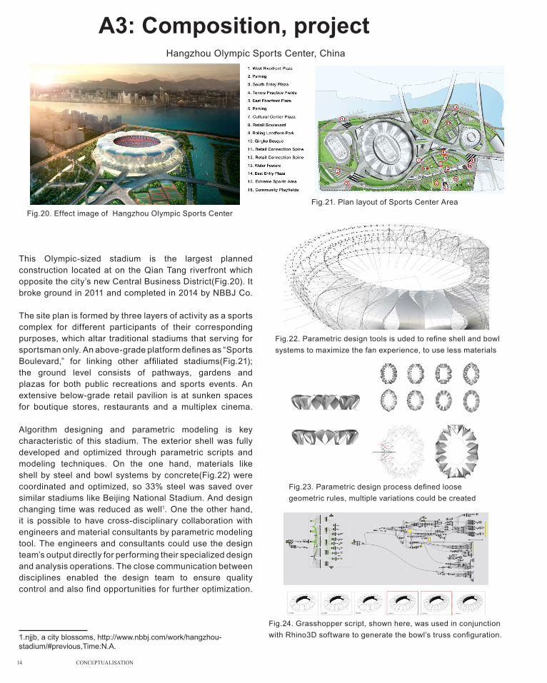
A3: Composition, projectHangzhou Olympic Sports Center, China
This Olympic-sized stadium is the largest planned construction located at on the Qian Tang riverfront which opposite the city’s new Central Business District(Fig.20). It broke ground in 2011 and completed in 2014 by NBBJ Co.
The site plan is formed by three layers of activity as a sports complex for different participants of their corresponding purposes, which altar traditional stadiums that serving for sportsman only. An above-grade platform defines as “Sports Boulevard,” for linking other affiliated stadiums(Fig.21); the ground level consists of pathways, gardens and plazas for both public recreations and sports events. An extensive below-grade retail pavilion is at sunken spaces for boutique stores, restaurants and a multiplex cinema.
Algorithm designing and parametric modeling is key characteristic of this stadium. The exterior shell was fully developed and optimized through parametric scripts and modeling techniques. On the one hand, materials like shell by steel and bowl systems by concrete(Fig.22) were coordinated and optimized, so 33% steel was saved over similar stadiums like Beijing National Stadium. And design changing time was reduced as well1. One the other hand, it is possible to have cross-disciplinary collaboration with engineers and material consultants by parametric modeling tool. The engineers and consultants could use the design team’s output directly for performing their specialized design and analysis operations. The close communication between disciplines enabled the design team to ensure quality control and also find opportunities for further optimization.
1.njjb, a city blossoms, http://www.nbbj.com/work/hangzhou-stadium/#previous,Time:N.A.
Fig.20. Effect image of Hangzhou Olympic Sports CenterFig.21. Plan layout of Sports Center Area
Fig.22. Parametric design tools is uded to refine shell and bowl systems to maximize the fan experience, to use less materials
Fig.23. Parametric design process defined loose geometric rules, multiple variations could be created
Fig.24. Grasshopper script, shown here, was used in conjunction with Rhino3D software to generate the bowl’s truss configuration.

CONCEPTUALISATION 15
A3: Generation, projectBeijing National Aquatcis Centre (the Water Cube), China
As the Water Cube was one of a spectacular buildings remembered by people during the 2008 Olympic Games, its design, engineering and construction have much replied on parametric design. Since humans controlling mechanical forces more powerful than the human body by using actual tool, now it gradually happens in architecture but software tools, they are developed specially for parametric design.
The Water Cube was built into parametric software, i.e. MicroStation V&I(Fig.27), which are used by architects and engineers to automate design processes and accelerate design iterations. It gives designers and engineers new ways to explore alternative soap bubble-like structure(Fig.25&26) without manually building a detailed design model for each scenario. It also increases efficiency in managing conventional design and documentation.
Since parametric design is about designing a system that designs a building.” the system on engineering and design services for the Water Cube was provided from ArupSport. J Parrish, director of ArupSport, helped pioneer the rapid prototyping face of generative design and began working with Microsoft’s Visual Basic and Excel — “a useful interface” — and MicroStation in the 1970s to design stadiums quickly. For the Water Cube case, by tweaking any of 3,000–4,000 parameters, Parrish was able to quickly compare(Fig.28). For example, various 50,000-seat positioning schemes and optimize them for views, distance from the field, and other factors.1
1. Cadalyst, Generative Design Is Changing the Face of Architecture - See more at: http://www.cadalyst.com/cad/building-design/generative-design-is-changing-face-architecture-12948#sthash.J9j9wVo5.dpufhttp://www.cadalyst.com/cad/building-design/generative-design-is-changing-face-architecture-12948, July 2008
Fig.25. The ceiling over main pool showcases the Water Cube’s “soap bubble-like” structure, which was designed with parametric software
Fig.26. The optimal design for the Water Cube was determined by analyzing multiple configurations of the thousands of steel members and connecting nodes
Fig.27. The Strand7 Finite Element model of the Water Cube
https://yeswebim.wordpress.com/2015/04/13/bim-and-scripting-beijing-national-aquatics-center/
http://continuingeducation.construction.com/article.php?L=5&C=418&P=3
Fig.28. Software that Arup developed helped designers optimize and size these components

16 CONCEPTUALISATION
A4: Conclusions
Through explorations of three parts, I further know about that architecture, as part of the design discipline, is continuously going forward with social conditions, technical conditions developing.
Part A explores design futuring topic, which is on how architecture shifts as social conditions changes. Human’s existence has encountered various challenges from nature or humans themselves, architecture has to focus on and solve these issues based on providing basic space needs.
Part B explores design computation topic, which is about revolutionary changes taken by widely using of parametric design on architecture itself and its participants. Architecture has shifted from conventional artificial thinking, molding and construction, to algorithm thinking, parametric modeling, and computational construction, so participants have to equip with this ability to deal with algorithm system issue, which also re-position their role in whole team, re-arrange their workload and their interactions with clients.
Part C explores composition / generation topic, further explores how parametric design changes architectural forms, materials, constructing period, etc. on composition and generation aspects. Parametric design also greatly affects outside fields of design, visualization and online sharing & teaching are typical examples.
In all, current architecture occurs huge and far-reaching changes today, which are required by needs on both coping with challenges, and various cost-saving to follow social trends. The appearance of parametric design is able to meet these needs, so it is widely used on architectural fields currently.

CONCEPTUALISATION 17
A5: Learning Outcomes
Through explorations of three parts, I further know about that aThrough learning this course, I gradually know about influences on current architecture taken by algorithmic or parametric design. Before I step into this field, I am always fascinated by those constructions by their ornate appearance and complex internals, but for how to construct them I do not have any conceptual knowledge. Through parametric design, I probably understand some of architectural components by knowing its core programming, so that ideas of how to construct them can be roughly described.
Learning parametric language is an experience that painful process while delightful result. Since this modeling system is not conventional method that sketching or changing on visual models directly like Sketchup, Rhinoceros alone, but to model a system language, which will display visual model automatically. Due to lacking of direct manipulation on visual model, I feel that manipulating on system model, rather than visual model is indirect, in particular, I have to encounter various parametric language errors, and errors seems never happen on visual model. However, once the system parametric model is built, compared to direct visual modeling, modifying is simple by just changing a cell without affecting the entire system, while on visual model those steps following changed cell needs to be modified as well. Therefore, lots of new concepts can be made by small changes without painfulness.
Also looking back at previous works, I find that parametric design is not only limited to architecture field, industrial design can adopt it as well. For example, in studio earth, if I adopt parametric design, i can quickly adjust the amplitude of path trail, and locations and quantities of support poles; in past industrial design works, if the material properties or user experience data were inputted in parametric design, some products may be impossible, while some may exit further exploration spaces.

18 CONCEPTUALISATION
A6: Bibliography & image references
Anthony Dunne & Fiona Raby, speculative everything,design, friction and social dreaming(publisher and time no stated),p3
Cadalyst, Generative Design Is Changing the Face of Architecture - See more at: http://www.cadalyst.com/cad/building-design/generative-design-is-changing-face-architecture-12948#sthash.J9j9wVo5.dpufhttp://www.cadalyst.com/cad/building-design/generative-design-is-changing-face-architecture-12948, July 2008
CTBUH research paper, Design computation for the 21st century high-rise, http://global.ctbuh.org/resources/papers/download/919-design-computation-for-the-21st-century-high-rise.pdf, 2012
http://www.infrastructurewriting.com/portfolio/magazine-article-written-for-bentley-systems/,2015
Infrastructure writing, Architecture Gets an Upgrade, http://www.infrastructurewriting.com/portfolio/magazine-article-written-for-bentley-systems/,2015
Inhabitat, Gallery Singapore’s Garden By the Bay, http://inhabitat.com/singapores-gardens-by-the-bay-features-the-worlds-largest-climate-controlled-greenhouses/cooled-conservatories-wilkinson-eyre-13/?extend=1 17 Jan 2013
njjb, a city blossoms, http://www.nbbj.com/work/hangzhou-stadium/#previous,Time:N.A.
Solar Building, Modelling of High-performance Envelope and Façadehttp://www.solarbuildings.ca/documents/Modelling_of_High-performance_Envelope_and_Fa%C3%A7ade_Integrated_Photovoltaic_Solar_Thermal_Systems_for_High_Latitude_Applications.pdf,2012
Tony Fry, Design Futuring: Sustainability, Ethics and New Practice (Oxford: Berg, 2009), p2
Weiheadline.arcticle, brick boxing house-Taolei Architect Studio, http://wtt.wzaobao.com/p/b785tE.html 17 Apr 2015

CONCEPTUALISATION 19
Fig. 1 Retrieved from http://www.123rf.com/photo_15294213_aerial-view-of-newly-opened-gardens-by-the-bay-singapore-river-and-marina-barrage-in-singapore.html, Time: N.A.
Fig. 2 Retrieved from http://www.gardensbythebay.com.sg/en/the-gardens/attractions/flower-dome.html, April 2015
Fig. 3 Retrieved from http://www.gardensbythebay.com.sg/en/the-gardens/attractions/cloud-forest.html, March 2015
Fig. 4-5 Retrieved from http://www.gardensbythebay.com.sg/en/the-gardens/attractions/cloud-forest.html#!/gardens, March 2015
Fig. 6-9 Retrieved from http://wtt.wzaobao.com/p/b785tE.html, April 17th 2015
Fig. 10-11, 13-14 Retrieved from http://blog.sciencenet.cn/blog-633348-861386.html, Jan 21st 2015
Fig. 12 Retrieved from https://www.facebook.com/8TV.NEWS/videos/975493162478326/?pnref=story, Jan 23rd 2015
Fig.15 Retrieved from http://www.chinabim.com/news/domestic/2015-04-20/11375_2.html, May 12th 2015
Fig. 16-19 Retrieved from http://global.ctbuh.org/resources/papers/download/919-design-computation-for-the-21st-century-high-rise.pdf, 2012
Fig. 20-24 Retrieved from http://www.nbbj.com/work/hangzhou-stadium/#previous, Time: N.A.
Fig.25-26. Retrieved from http://www.cadalyst.com/cad/building-design/generative-design-is-changing-face-architecture-12948, Oct 19th, 2008
Fig.27. Retrieved from https://yeswebim.wordpress.com/2015/04/13/bim-and-scripting-beijing-national-aquatics-center/, Apr 13th, 2015
Fig.28. Retrieved from http://continuingeducation.construction.com/article.php?L=5&C=418&P=3Oct, July 2008

A l g o r i t h m sketchbook part A

W01_ LOFTING

W01_ SWEEPING

W01_TRIANGULATION 2D

W01_ TRIANGULATION 3D
Count:10Group:2
Count:20Group:2
Count:40Group:2
Count:40Group:6
Count:40Group:10

W02_VECTOR&MESH GEOMETRY

W02_VECTOR&MESH GEOMETRY W02_ CURVE MENU

W02_ TRANSFORM MENU

W02_ Detailing Planar Joints

W02_ Contours, sections, Curve Intersections
Pyramid successive section still fails,exploring...


PART B CRITERIA DESIGN

B1: Research fields_Strips & FoldingStrips/folding is the form that characterized by folded or curve shape on surface which is still made up of basic small free-form curves, surfaces, or volumes. In parametric algorithmic design system, those basic forms are banded, linked and bended as a surface, followed by being folded to a intricate cube.
Greg Lynn, who wrote a book named “ Folding in architecture”, emphasized the imporatnce of folding in structure and facade system. He stated that architectural complexity in both composition and constructioncontinues as folidng is widely used in construction, and folding is also developed to a “metophor” filed to demonstrate its existing. 1It is true. Classical strips and foldling is normally demonstrated on detail components but the structure of mian construction is either vertical or horizontal, like Feiyang in traditional Chinese buiding or capitals in Greek columns. With the technics developing, folding types can be widely used in main structure so that construction form can be formed vivid than ever.
Computational design takes strip or folding shape another chance to revolute itself. With continous iterations, alterations, or overlapping, folding can be changed, added or omitted easily without any economic wastes while reaching the target that desginers want.
As for its fabrication concerns, it is much easier to be manufactured with the aiming of certain tools to a certain folded angle. Additionally, folding is sometimes a god way to save materials since curves sometimes are shorter than two straight lines and also waste materials are reduced compared to ancient time.
Therefore, even current strip/folding system is a complexity when seeing, it can be manipulated by certain tools, modifying whole construction structure readily and also save time as well as materials.
1. "Folding in architecture", Greg Lynn, https://arch629eldridge.files.wordpress.com/2010/04/read-to-p23wk14-lynn-et-al-folding-in-architecture.pdf
CO-DE-IT, LOOP 3
Strips is adopted thoroughly in this structure. First, strips form its base. The base of this structure can be seen as a triangle or three ellipses banding together initially. However, with the strip curved line, the shape beomes one unit without obvious angles. Secondly,strips makes the base centre stand up. The strips concerntrating to centre makes this structure extend vertically while standing on ground with its three feet still. Thirdly, three wings are “inflating” with the distance further away from centre point, which is rovolved smoothly at end by strip shape Fourthly, the structure above is bigger than bottom but still standing stable. By using strip shape at each wing vertically, it can transfer the load homogeneously to ground without any abrupt angles or rotate at edge.Fifthly, strip makes this structure in multi-layer in a gradient form.The second top layer of wing is the biggest area, followed by decresing area to two ends, which makes it aesthetically smart.

GALAXY SOHO,BEIJING
Strips is adopted both at main four main tower structure and their linking corridorsFirst, strips form every tower edge horinzontally, which makes it like a round or ellipse if from top view.Secondly, strips shpe form every tower vertically. Seen from side view, ithe vertical edge is bigger at middle point while deflate at two ends, which demonstrates its gracefull feelingThirdly, strips from the top of each tower. Seen from outside, it seems that no flat ground for people standing since stripe-shape roof is adopted up to highest line tehn downFourthly, strips are used at each linking corridor edge horizontally.
ICD/ITKE Research Pavilion 2010.
Strips and folding are both adopted at this construction.First, Strip line is used at timber bottom edge horizontally and vertically. Through horizontal aspect, it forms a round shape while the height of people standing area(see people on image) is a bit higher than height of glazing French window area.Secondly, strip is used at top so that no abrupt angle existing from outer edge to top then to centre round hole.Thirdly, folidng shape is adopted at its component of main structure. It seems that the structure is made up of five layers of stereo circles while each circle consists of about 50 pieces of “foldling timber”. These folidng timbers are folded as annulation things and ranged side by side. Of course, annulation things are stripes themself also since it is round or ellipse fromside view.

B2: Case study 1.0
Biothing pavilion is charactered by its self organising and adaptive systems, followed by transferred each of "cluster" into different scales1.Each cluster consists of several curved dropping pipe orgins from one centre like a umbrella, and these different scaled clusters are linked at cluster centre by a main curved pipe.
Due to the computational design system, the curved lines can be added and modified themself by adjusting varied data on a few magnetic field. Every magnetic field will affect surrounding magnetic fields, so that those curves demonstrated by a magnetic fields is modified.
I choose this structure for two reasons. Firstly, it demonstrates a curved shape that only formed by many basic curve line, which is suitable with my proposal on curving shape in Merri Creek.Secondly, the realtionships of each clusters that will interact surrounding shapes between them is another lightspot. Since my proposed structure will be manipulated by simple but near distance objects, i need to focus on the interations between each componenets.
1."‘biothing’ – a transdisciplinary lobratory founded by Alisa Andrasek", Posted by Nora Schmidt on 05.11.2009http://www.dailytonic.com/biothing-a-transdisciplinary-lobratory-founded-by-alisa-andrasek/

Biothing Pavilion
Biothing pavilion is charactered by its self organising and adaptive systems, followed by transferred each of "cluster" into different scales1.Each cluster consists of several curved dropping pipe orgins from one centre like a umbrella, and these different scaled clusters are linked at cluster centre by a main curved pipe.
Due to the computational design system, the curved lines can be added and modified themself by adjusting varied data on a few magnetic field. Every magnetic field will affect surrounding magnetic fields, so that those curves demonstrated by a magnetic fields is modified.
I choose this structure for two reasons. Firstly, it demonstrates a curved shape that only formed by many basic curve line, which is suitable with my proposal on curving shape in Merri Creek.Secondly, the realtionships of each clusters that will interact surrounding shapes between them is another lightspot. Since my proposed structure will be manipulated by simple but near distance objects, i need to focus on the interations between each componenets.
1."‘biothing’ – a transdisciplinary lobratory founded by Alisa Andrasek", Posted by Nora Schmidt on 05.11.2009http://www.dailytonic.com/biothing-a-transdisciplinary-lobratory-founded-by-alisa-andrasek/

1 2 3 42.
Add
ing
spin
fiel
dan
d po
int c
harg
e1.
Mod
ifyin
g cu
rves
3. S
tick
shap
e4.
Strin
gs fo
rm
surf
ace(
s)
Change curve shape and add decay parameter
Add divide points on main "stem" curve
Increase radius data of circles on main "stem" curve
Increase division point a long c i rc les on main "stem" curve
Add one field spin Add multi-field spins, strength positive and negative
Add more points on curve divide, Point spin exist with Field spin
Change parameters on circle that before field line, offset more circles
5. M
ore
emph
asiz
ing
on F
ield
spi
n
Add multi-field spins, strength positive and negative
Modify data in point field and field spin before field spin
Modify data in graph mapper A d d o n e - t w o s i n e g r a p h mapper
Delete curve and keep point filed as orgins
A d j u s t d a t a a f t e r f i e l d line,including graph mapper, add data on charge
Add s ine graph mapper, parallel with Bezier graph mapper
Graph mapper are multipled by different parameter units
Add many field spin and just keep two point field
Add decay on field spin Add decay on field spin, use ellipse to replace circle before field line, unit Z to move it
Change scale one graph mapper

5 6 7 8
Increase division point a long c i rc les on main "stem" curve
Decrease division data of Field spin and range data
Change graph mapper shape and scale, keeping Bezier curve type
Change graph mapper type from Bezier curve to sine curve
Add perlin graph mapper type with initial graph mappers
Change parameters on circle that before field line, offset more circles
Change parameters on circle that before field line, offset more circles
Change graph mapper type by sries battery controlling
A d d s i n e g r a p h m a p p e r controlled by range battery with Bezier graph mapper
Simplify data on field spin, delete points and keep curves, increase "N" in field line
A d d o n e - t w o s i n e g r a p h mapper
A d d o n e - t w o s i n e g r a p h mapper
A d d t w o s i n e g r a p h mapper,change data on sine and bezier graph mapper
Add decay on spin field and much change on this data
Simplify graph mapper, add a point on initial circle
Graph mapper are multipled by different parameter units Add decay on point field,change
radius of filed lineCircles left of field line is linked with several planes
Much adjusting data on graph mapper
S i m p l i f y g r a p h m a p p e r, u s e rectangles to replace circle before field line
Change scale one graph mapper
Change graph mapper from Bezier line to sine line
Add unit Y and perlin graph mapper
Add mataball components on initial points
Add pipe of different radius at two ends on before field line

Chosen designSelection criteria:
1.. Intriguing: the shape can reflect somethings in the real world, allowing people to connect other things2. Doubled/Multiled: the shape needs to be duplicated of the same shape3. Covering: the shape needs to expose a large area rather than a long stick or a few small dots only.
2.2 3.7
4.6 5.7
2.2: i choose that because it is not only like a group of tadpole, but also it is made up of by repeating tadpoles and showing a dynamic shape in water. Origins from Biothing pavilion, the cluster centres are seen as "fixing dots", while with dynamic long curves behind like tails. It will help my further design on something on water surface.
3.7: i choose that because it is like two up-side down bottles whereas they share a same bottle bottom at top. Since my future proposal exists somethings that hang on ends of curved high stick, so it wakes me a lot.
4.6: i choose that because it is like a snail shell or sea conch. Its shape exists a centre and sweep biggger and bigger surrounding this centre. It embarks me on its relations between surrounding issues and centre issue, how they interact each but still keeping on two different things.
4.6: i choose that because it is like several black holes in universe with heavy and light suction power. Even though each of black holes intersect half of its volumns, they can be seen clearly still. My proposal exist intersection from top view, so how to deal with is a problem that i need to solve.

B3: Case study 2.0Slicing Opacity Pavilion in Silico Building
This part of case study is about reverse engineering. The project i choose is slicing opacity pavilion in Silico Building. The reason i choose this structure is because it not only exists the charateristics of stripes/folding shapes, but also somethings that to connects a series of stripes/folding shapes that resembles my thinking for Merri Creek.
1.Stripes/folding shapes: It is obvious to be demonstrated from its layers of sections. For each section, it is like a storey that demonstrate an irregular curved-edge shape. However, every layer are connected by this shape and from bottom layer to top layer, they demonstrate a process of gradient shifing, normally bigger at bottom and smaller at top.
2.Multi-shape connections: These shapes are all supported by vertical issues like long bolt or glasses that passing the load from up layer to down layer until bottom supporters to ground. This kind of supporting method guaranttes the shape to be stable, no matter what kind of shape above or the shapes deviate to which directions, the supporers can be added to more density at certain areas to make sure a stable structure
3. Materials: Since the struture is normally made up of two issues, one is horizontal multi-layer sections and the other is vertical supporters, two different types of materials are adopted. For front, they are non-transparent to offer clear vision to show that they are layers, to provide paltforms to stand or place things on them; for rear, they are non-section vertical things except transparet glass, so it seems that they are not existing but they are indeed crucial. Without them, the structure will collapse.

Reverse engineering
CURVE OUTVERTICAL
CURVE OUTTOP
CURVE OUTBOTTOM
CURVE INVERTICAL
CURVE INTOP
CURVE INBOTTOM
SWEEP 1RAIL
SWEEP 1RAIL
END(S) PDECOM(Z)
A/BNUMBERSLIDER(INT)
OUTERCONTOUR
INNERCONTOUR
UNIT Z
UNIT
BOUNDARYSURFACE
OFFSETSURFACE
NUMBERSLIDER(NEG)
UNIT Z
STAGE 01 STAGE 02 STAGE 03
STAGE 01 STAGE 02 STAGE 03

Z
TACE MIRROR
EXTRUDE
ADDITION(+)
OFFSETCURVE
DIVIDECURVE
MOVE MIRROR LINE PIPE
NUMBERSLIDER(R)
NUMBERSLIDER(NEG)
NUMBERSLIDER(INT)
MOVE
UNIT Z
STAGE 03 STAGE 04 STAGE 05
STAGE 03 STAGE 04 STAGE 05

B4: Technique development1.
Mod
ifyin
g su
ppor
ters
of
str
uctu
re b
u ad
just
ing
divi
sion
, ite
m li
st1 2 3 4
2. M
odify
ing
over
all
shap
e by
adj
ustin
g to
p,
dow
n an
d si
de c
urve
3. M
odify
ing
Kna
groo
on
supp
orte
r and
pla
tform
Curve Point offset controlled by range
End points manipulate circles into one big one small and loft
Shift points to two side and make weave
Add arc component on points
Top curve b igger wh i le b o t t o m c u r v e s m a l l e r, changeparametre to make more section layer
To p a n d b o t t o m c u r v e change location to limit
Rotate that volumn to varied rad ian to make severa l volumns combine together
Change top and bot tom curve to polygon, and rotate middle part of section layer
Outside surface shell mesh
Inside core surface mesh to smaller
Section layer surface mesh to make bigger and concave -convex
Section layer mesh to merge storey, offset supporter points to corresponding location

5 6 7 8
Add rectangle on same vertical line points
Add rectangle on random points
Offse t d i f fe ren t distance and loft
Change top and bot tom curve to polygon, and rotate middle part of section layer
Change section layer th inkness by range component
Bot tom curve choose round curve and top curve choose polygon curve
Section layer mesh to merge storey, offset supporter points to corresponding location
Mesh supporter as inflation and deflation
Use basic shape as foundation to make pavilion

1 2 3 44.
Mod
ifyin
g su
rfac
e su
bdis
ion
on v
ertic
al fa
cade
5. M
odify
ing
who
le s
uppo
rter
s by
wei
rd p
ipe
and
jew
els
6. A
dopt
ing
jitte
r and
sca
le
on s
ectio
n sh
ape
Outside surface subdivision to make different radius circles
Both outside and inside core surface subdivision in different density
Subdivide outside surface to re-make hundreds of triangle panel surfaces
Two sets of Triangle panel surfaces, one is offset to out
A d o p t j i t t e r a n d s c a l e b a s e d o n orginal base shape
C h a n g e s e r i e s parameter that control scale component
Change series parameter to negative number
Change series parameter that control jitter
"Move" component that control original curve, i ts "N" in series component is increased

5 6 7 8
Put image sampler component on surface and loft
Two sets of Triangle panel surfaces, one is offset to out
Adopt brep closet point and trim on outside surface
brep closet point and trim is adopted on section layer
Change series parameter that control jitter
series parameter that control jitter is changed to range rather than one number
Jitter 's j i t ter and seed are modified
Jitter is unfunctioned, only left scale to be functioned

1 2 37.
Ado
ptin
g gr
aph
map
per
on o
vera
ll sh
ape
8. A
dopt
ing
pfam
es a
nd v
onor
oi to
sw
ay s
ectio
n an
d su
ppor
ters
Add one graph mapper(Bezier ) to control rail curve
A d d f o u r g r a p h mapper(Bezier) to control section curves
Add 2-3 other type of graph mapper(perlin,sine) on initial oen Bezier graph mapper
Much change on shape of graph mapper
Adopt Pframes and brep/plane to make section layer sway rather than standard level
Cull pattern to control pipe, brep/plane
Change direction of outer rail and inner rail, and top&bottom curve direction
Adopt pop2D and vonoroi as frame supporter to replace previous broken supporters

4 5 6 7 8
Much change on shape of graph mapper Deflate mapper shape, so
making section layer deflation as well
Adopt pop2D and vonoroi as frame supporter to replace previous broken supporters
Vonoroi with pop3D, make poin ts up a long un i tZ as supporters
Add metaba l l and o f f se t component
F o l l o w e d b y m e t a b a l l , extruding it and cap

Chosen designSelection criteria:
1. supporting: the section layers are not supported by conventional columns, vertical stickes,etc, but by boards, outside facades,etc.2. Section layers: should be weird, dynamic, splice shaped,etc, rather than a whole piece.3. Overall layer shape vertically: should be somethinngs that curved, concave and convex rahter than a straight line.
1..6: i choose it because it is supported by random panels at each section (2-3 panels), which will strength my futher model on trying different supporters.
4.6: I choose it because the section layers are not conventional, they are looped by an outer and an inner surrounding line, but break one piece again and again. Also for each section layer’s break, they are like sunshine from centre core hole.
6.2: I choose it beacause it resembles wind erosion rock in natural. Even supporters are not seen from outside, a core central supporter is in centre to link hundreds of varied shapes of layers. It is a good practise for me to resemble something that origins from nature directly, and for my future model on Merri Creek
8.4: I choose it beacause the overall main struture is not that section layers but a extruded “shelf” while the section layers are set to be an affiliated issue. Meanwhile, the “shelf”’s inner partitions become supporters to fix that section layers on this shelf structure, which make traditional column supporters to be thrown away.
1.6 4.6
6.28.4

B5: Technique: PrototypesTechinique focus: Strip-shaped Section with vertical tree links
The idea of this focus origins from two aspects. On the one hand, aquatic birds are not always swim in water. They sometimes will stand on platforms(refer to image 1 and 3). On the other hand, they likes to swim along bank especially where lush plants grow(refer to image 2). So i would like to combine these two elements, to construct some man-made things that in water but along the bank to offer them good places
Image 1
Image 2
Image 3
First step: Long section but only one layer + higher parallel "plants", they connect only at one pointResult: The outcomes was not quite well since if the plants are too high and only fix with that section at lower position, they can not intersect each other to make compression and tension, so they are easily collapsing.
I had to use glue to fix one side to test its outcomes. It is better compared with the side that without glues, but compression and tension still can not be made through this method.
As for the fastness issue of that section, the result showed that it is stable since i made joinery with those "plants" which add friction force.
Conclusion: Multi-layer section will be adopted and plants have to be shortened
Above image: bottom row of plants are glued while upper side of plants almost are not glued, almost collpsing

Second step: Short section but multi layers (I put two layers first) to decrease the friction force of joinery+ shorter round "plants", each plant connect at two points with section layers
Result: The outcomes was better than first step since even though the main bigger layer section is at lower position like first step, those plants intersect each other through second layer of section,which is like two clips to hold two ends of a string and make this string not to be skew.
Since for those two layer section of that structure, one is joined at out edge of plants and the other is joined inner edge of plants, the lower one produces compression while upper one produces tension, both section layer and plants are stable.
Conclusion:Multi-layer have to be adopted, better one is in and the other is out
Third step: Re-use first step structure and add another section layer out of plants, to test whether the struture is strengthedResult: The outcomes was better than first step but still worse than second step round one, since i mix the plants location with digital ones, and once the prototype model's joinery can not be suitable with temporary arranged plants, the top section layer will not be supported by plants. So all structure will easily collapse. In addition, i believe that both section layers are out circles will lead to lacking of tension load to high "plant" especially at top part I must add one section layer inside circle like step2, to add some tension.
Conclusion:Section layer have to include both outer circle and inner circle; if the section layer is long and connect with lots of plants, the joinery must be accurated precisely and plants can not be mixed
Stable on both section layer and vertical plants

Fourth step: To replace upper outer circle to inner strip(since the strip space is limited, i do not make a hole as step two) to add tension to structure
Result: The outcomes was better than third step but worse than second step, since the strip shape is long and joinery to plants are harder to control compared with step two. I believe that mixing plants with initial joinery is another reason, but through the test one outer strip circle and one one inner strip (circle) is a must, to strenth both section layer and high plants
Conclusion:High plants is not problem, but long strip shape have to be more careful on its joinery issue. Both outer strip circle and inner strip are have to adopted to strength both compression and tension.

B6: Technique: ProposalPlanted Platforms for water birds on
The connection area of Merri Creek and Yarra River is inhabited by many water birds. Sometimes they like to stand on rocks above water surface; sometimes they like to swim along water bank in and out lush plants even step on land.My proposal is to observe and analyse these habit and propose best planted platforms for multi-purposes.
Multi-layer section platforms for them to remain on.
Platforms that built at deep-water area can offer water birds another choice to sway other than shallow water near river bank.
Man-made planted-shape scupltures can keep the flourish of plants when winter comes
Vertical "plants" and horizontal "platforms" can shade part of strong sunlight when summer comes.
Good place to shunt running of water-flow so that algae will grow up there, followed by fish comes which attracts water birds comes as a food-hunting place.
Platforms offer places for soil and plants seeds being blowed on it, so it is possible that real plants grow up on it mixing with man-made vertical "plants"
Deep water level by dam, water surface wide, water flow slow, seldom natural rock or plants can grow from water
Rapid water flow, hard for water birds to swim inside
Shallow water level,narrow water surface, many rocks and plants can expose out of water surface
There fore , the b lue area is my destination to set this planted platforms

Proposal i: Single cluster
Proposal ii: Multi clusters

From B5 process, I have tried to explore the relations of section layer numbers and shape, as well as supporter height. How these two elements affect the stability of my struture.
Joinery struture will be much applied in this struture no matter to join components in one cluster or one cluster and one cluster joinery. However, since the struture is in water and the lower part of this struture is soaked in water, special fixing methods have to be adopted to make sure it is stable forever.
Since timber material will be corroded if soaked in water for long time, i think that metal material have to be adopted for “plant-shaped” supporters even though the surfaces of these metal resemble timber. Meanwhile, rock or grass texture surface material can be adopted for section layer but they have to be lightweight and smaller-scale from lower level to top level.
Fabrication and material thinking
From B1 to B4 process, the two structures, Biothing Pavilion and Slicing Opacity Pavilion in Silico Building wake me a lot on thier technique applications.
For biothing pavilion aspect, i adopt its several clusters on one curve, then the whole structure is made up of a few curves with these clusters. It was achieved by divided points on curve generating points fileds and interact together.
So my struture is also as clusters to be linked together(refer to proposal ii) along the river bank. Even though i do not adopt point field or spin field on my own design, each cluster have to interact each other though higher and lower section layer. One cluster’s plants forms also may also affect another cluster’s plants or section platform, so this is what the field component in grasshopper that wakes me.
Technique thinking

B7: Learning Objectives and outcomes Objective 7. developing “the ability to make a case for proposals
Actually there is a big gap between digital approaches and practical approach. In digital approach that adopts grasshopper, the shape can be stimulated by just piling, but through practical model i find that small joins or small gap will the whole struture not in an completed shape or collapsing. However, though practical model i can make some mistakes that digital model doing wrong or never being considered to perfect my proposal.
Objective 8. begin developing a personalised repertoire of computational techniques.
I am able to develop some of personalised repertoire from initial algorithm programming but not fully mastered, especially when i face some simple programming that the shape itself can not be changed too much like in B4. Additionly, some components in grasshopper that relevant seldom using will also stuck me to program further complex programming.
Objective 2. developing “an ability to generate a variety of design possibilities for a given situation”
Since i have not much researched in detail on my target clients, water birds like in Mebourne, what they eat, what kinds of plants they are refer to be habitating, my design proposed possiblity is limited,which means only one to two shapes or functions can be put forward.
Objective 3. developing “skills in various three-dimensional media”
In three dimension rhinoceros and grasshopper from B2 to B4, i can do different media by showing varied shape on technique development, but in the prototyping process afterwards, since my reaserach field have not expanded in details, i can not put forward various 3D media that shot on certain points accurately. In addition, prototyping is another shortcoming since i made it simple as much as i can so that the judgers felt that my model can not show praramtric elements
Objective 7. develop foundational understandings of computational geometry, data structures and types of programming
IN opinion, in B2 case study1.0 i can showed my understanding exactly according to parametric data shifting, in B4 my reverse-engineering program, my techinique development is not as good as B2 since some parametric data is leaping and i do not know how to transit them smoothly. in B6, even though i use grasshopper to made digital model first, it is still to see the computational elemnents inside.

A l g o r i t h m sketchbook part B

W03_ Gridshell and patterning

W04_ Field, Expressions, Fractal Tetrahedra

W04_ Field, Expressions, Fractal Tetrahedra

W05_ Evaluating Fields

W05_ Evaluating Fields

W06_ Tree issues and path mapper

W08_ Kangaroo application

PART C DETAILED DESIGN
MORPH

PART C DETAILED DESIGN
MORPH

C1: Design concept(OCT 6th-16th)
My Part B critical feedback:
1. Good algorithmic skills user, even though did some unrelevant iterations in B4 at last.
2. Should adopt my algorithmic skills into my conceptual design more.
3. Construction and load relations are explored in B5, which is good
4. Bad conceptual design, lacking of real situation thought, target users are not deeply researched, much more aspects should be considered if users are animals
5. Can not see section elements in my conceptual design since section panel that adopting is rear.
For part C, Chen assigned the groups based on project direction. Our group members are Sarah Haque, Timothy Tan, Yicheng Sun and me initially. Sarah withdrew our group after the assigned group was set up, but she still made some suggestions on our conceptual design during the first week. Our script project is section.
OCT 6th 2015 group meeting with Chen, contents are as followes:Other team members' feedback on part B:
Sarah: Concept of section panels to prevent people from droping from high places is interesting.
Tim: Good at visual presentation(since he did not present in front of us, i hardly analyse his concept)
Sun: Limited work on part B
POSSIBLE PRECEDENTS:
Custore pavilion Cspace pavilion kengo kuma pavilion
Transparent churchlight and shadow feeling
Sectional space and fururnitureVertical sectional panel link top(space) with down
FROM INDIVIDUAL TO COLLABRATIVE

C1: Design concept(OCT 6th-16th)
For part C, Chen assigned the groups based on project direction. Our group members are Sarah Haque, Timothy Tan, Yicheng Sun and me initially. Sarah withdrew our group after the assigned group was set up, but she still made some suggestions on our conceptual design during the first week. Our script project is section.
OCT 6th 2015 group meeting with Chen, contents are as followes:Other team members' feedback on part B:
Sarah: Concept of section panels to prevent people from droping from high places is interesting.
Tim: Good at visual presentation(since he did not present in front of us, i hardly analyse his concept)
Sun: Limited work on part B
kengo kuma pavilion
Almost zero waste on original board, taking advantage of whole materials
Zero fold pavilion
FROM INDIVIDUAL TO COLLABRATIVE

OCT 7th-10th 2015 concept step 1:Since all of four persons' ideas are not very outstanding and persuaded, we have to come up with a new idea together. This is the first period that we come up with our ideas individually.
My idea: I develop my initial idea from animals to plants, to design some 3D platforms that made up by sectional panels, offering low plants (e.g. grass, flower, trellis,etc) to grow there. It will be located at a steep highland wall along Yarra River since the bottom of that wall is casted by concrete while upper part is mussy weeds. Human made 3D plants platform can add its attractions and order.
LOCATIONLOCATION SCENARIO REFERENCE IMAGES "Hung" platform for plants
Sun: Design something that like a deck chair for vistors' resting, relaxing in cool place,etc.
The sect ional mul t i -panels are overa l l perpendicular to ground, with small space intervals for people's comfortable sitting on it
Conclusion: Doing a Shading plus Phone Charging Port Structure When this structure is not in use it will act as a shading for anyone to sit under but most importantly it is going to be a charging portal for people who need to charge their phones when their phone battery is almost dying. The shading part will be used as parametric sectioning and charging ports Additionally, light will penetrate gaps between sectional panels that attracting people to the structure especially at night time

Since all of four persons' ideas are not very outstanding and persuaded, we have to come up with a new idea together. This is the first period that we come up with our ideas individually.
My idea: I develop my initial idea from animals to plants, to design some 3D platforms that made up by sectional panels, offering low plants (e.g. grass, flower, trellis,etc) to grow there. It will be located at a steep highland wall along Yarra River since the bottom of that wall is casted by concrete while upper part is mussy weeds. Human made 3D plants platform can add its attractions and order.
REFERENCE IMAGES "Hung" platform for plantsSarah: Design something that like a charging pole tool, that allows visitors to charge their handphone since the Merri Creek public path is a long path that visitors' handphone battery will not in power very soon.
The horizontal multi-panels to put handphone are as sectional components, penetrated by one central thick pole
Based on Sun's idea, i find some precedents on chair/furnitureConclusion: Doing a Shading plus Phone Charging Port Structure When this structure is not in use it will act as a shading for anyone to sit under but most importantly it is going to be a charging portal for people who need to charge their phones when their phone battery is almost dying. The shading part will be used as parametric sectioning and charging ports Additionally, light will penetrate gaps between sectional panels that attracting people to the structure especially at night time

OCT 10th-14th 2015 concept step 2 (Sarah withdrew):
Leaning and shading part - small log interlaced joining
Sample:Seating concave part contours
Based on Chen's feedback, we decided to combine charging elements and chair elements together to be as an interactive chair, i.e.the chair can be rocked while transferering its kinetic power to electricity power for phone charging; or the chair can transfer its solar power by taking advantage of the shading part but it is unrocked
First concept:A doubled-combined chair that shape is orginal from Chinese symbol "Taiji", one is facing north that used for morning sun, and the other is facing south that used for afternoon sun(Orientation needs to be re-thought). Then phone is put at small cabinets at leaning part at back, taking advantage of solar power generating from top shading panel.
(Green lines shows how the sectional panels probably extend on sitting part)
Shortcomings: 1.Stable, hard to rotate/move, so its top solar panel's orientation to sun will be affected; 2.Hard to fabricate by sectional panels especially at two chairs joining part
Second concept:Based on those shortcomings that we find during discussion,Tim suggested that the chair can be simplified to only one "concave" but can rotate 360° of its whole construction like an "Executive Leather Chair"
It shows that what i try to adopt the horinzontal and vertical coutours into "seating part" as lists of section panels)

OCT 10th-14th 2015 concept step 2 (Sarah withdrew):
Seating concave part - panel joiningLeaning and shading
part - small log interlaced joining
Based on Chen's feedback, we decided to combine charging elements and chair elements together to be as an interactive chair, i.e.the chair can be rocked while transferering its kinetic power to electricity power for phone charging; or the chair can transfer its solar power by taking advantage of the shading part but it is unrocked
First concept:A doubled-combined chair that shape is orginal from Chinese symbol "Taiji", one is facing north that used for morning sun, and the other is facing south that used for afternoon sun(Orientation needs to be re-thought). Then phone is put at small cabinets at leaning part at back, taking advantage of solar power generating from top shading panel.
(Green lines shows how the sectional panels probably extend on sitting part)
Shortcomings: 1.Stable, hard to rotate/move, so its top solar panel's orientation to sun will be affected; 2.Hard to fabricate by sectional panels especially at two chairs joining part
Second concept:Based on those shortcomings that we find during discussion,Tim suggested that the chair can be simplified to only one "concave" but can rotate 360° of its whole construction like an "Executive Leather Chair"
Shading with solar panel part
Back leaning with phone charging part
Seatingconcave
part

OCT 14th-16th 2015 concept step 3 (final chosen concept)Chen was not satisfied with our chair concept since on the one hand, it is complex to be munipulated and assembled; one the other hand, the second concept of chair is almost same like normal chair shape and it is much boring(compared to first concept of chair). So we have to drawback to original starting point. After i showed those "sectional plant platform" images and this concept to Chen again, he helped us to do something interesting shape like this platform, but asked us to think new concept that to be suitable with this shape and target site/users, and also tried to adopt the "zero material waste" concept to its individual panels.
Target purposes we have thought: 1.Carrier for hanging history information boards to show history of Merri Creek (high density panels); 2.Barrier to orb a round as a toilet/dressing room (high density panels)3.To hang potted plant at concave part on verical facade (very high density panels)Shortcomings: High density panels will take lots of time to fabricate..We dont believe that we have enough time to prototype,fabricate, and assemble so many panelsSolution: To think somethings that are low to medium density panels adopted
Final concept: To be as a shelf(low density panels) combined with a common barrier (low to medium density panels, not for toilet, dressing room that privacy purpose type).... But where is the target site?

Proposed site context
Proposed clients
When farmer's market opened --- consumers and retailers When farmer's market closed --- children/parents and livestocks

The site we finally choose is Collingwood children's farm. It is a large area of plain natural meadow.It is used for argricultural products' market once a month, and retailers will set up their temporary shed and storage rack one by one there; in other time, it is used for parking most of time as well as grazing sometimes. Without any barriers or entrances around, people can be easily accessible to there to park cars or play with those livestocks.
Currently, there exists another piece of grazing area being used at north side of our target place(blue circle indicates). However, since two areas are connected in centre, and meadow shall be preserved after a period of grazing, this red circled area can be developed as another grazing area alternative with the blue circled area when there is no farmers' market.
When farmer's market closed --- children/parents and livestocks

Current scenario --- missing pointsWhen farmer's market opened1.Common storage rack has to be unfolded and folded within a day, heavy to transport, occupy spaces when carry2. Common storage rack is lower height and less levels, can not put many things on it3. When storage rack is unfolded, it will occupy large spaces, and check-out counter sometimes is far away with sold issue
When farmer's market closed1.There is not enough barriers to enclose this new grazing land2. Traditional barriers (like barriers in above image) are stable and unmoved, it is not convenient for both consumers and retailers when farmer's market is opened3. Traditional barriers are rigid and stiff, not very visual smart.
Conclusion: What we do for our multi-section issue should be:1. Farmer's market opened: Flexible to rotate each "vertical screen"; not taking many spaces when folded; one screen's height can be as "check-out counter" that is next to other screens2. Farmer's market closed: Can be unfolded to any shape to enclose certain areas(if total length is enough, otherwise more have to be used; Dynamic to move; visual smart and appreciated

Technique: Zero material exploration
In one board, a list of stripes will be arranged vertically. Since the top and bottom edges of each stripe are coincident, no materials will be wasted during cutting process. In order to make every stripe's shape vivid, curve line edge has to be adopted rather than straight lines. However, if every curved line's shape is totally different, the effect of overall article consisting of different shapes of curved stripe is hard to predict.
Therefore, based on our analysing, each of our section panels will adopt coincident edge(exclude top one and bottom ones) and same curved shape if possible.
Zero fold pavilion
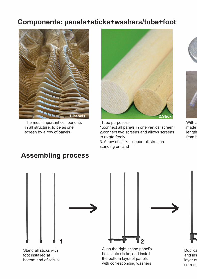
Components: panels+sticks+washers/tube+foot
1.Panels 2.StickThe most important components in all structure, to be as one screen by a row of panels
Assembling process
Three purposes: 1.connect all panels in one vertical screen; 2.connect two screens and allows screens to rotate freely3. A row of sticks support all structure standing on land
With a few washers piling up, or ready-made tube that be cut corresponding length, to separate each upper panel from below panel
Stand all sticks with foot installed at bottom end of sticks
Align the right shape panel's holes into sticks, and install the bottom layer of panels with corresponding washers
Duplicate the second step and install all the second layer of panels with corresponding washers
1 2

Components: panels+sticks+washers/tube+foot
With a few washers piling up, or ready-made tube that be cut corresponding length, to separate each upper panel from below panel
Duplicate the second step and install all the second layer of panels with corresponding washers
Duplicate second and third step and finish to install all the layers of panels
Same diameter with stick, can be installed accurately at bootom end of stick for more stable standing
3.Washer/Tube 4.Foot
3 4

Form possibilities: multi-purposes
Ring shape with one entrance/exit:Used for private issues that only allows one person/family entering in
Totally-Folded:Used for non-using
Extended as a line:Used for barrier to enclose a large area, standing at the boundary, or put some veg and fruits on it if the ground is enough wide

Totally-Folded:Used for non-using
Ring shape without gap:Used for enclose some important issues that trees at meadow to prevent sheep chewing bark
Half folded:Random put on meadow, prepare to be used for some purposes
Check-out counter: The entrance/exit is just in front of check-out counter for convenient settling

We analysed this issue from the board size that fablab offers us since i want to explore the most efficient way to manipulate. The shape is 2400mm(length) x 1200mm (width) on both boxboard and MDF board that we might use. We started to calculate the board from its shorter edge (1200mm) for its easier components array than longer edge (2400mm) if each panel on mockup is not too big (<200mm)
After that, we tried to confim how big of each panel is in real scenario. We took the self in our fablab as a precedent (750mm width of each cabinet) and thought that our panel should ±200mm of that precedent (550mm-950mm).
As in mock up, if we arranged 10 pieces of panels along shorter edge (since 1200÷10=120, it is an interger which is convenient to array them on a shaped board), each mock-up panel is 120mm length. And if the scale we do is 1:5, the real panel's length is 600mm, which is between 550mm to 950mm that mentioned.
In addition,since what we want to do can be as a shelf, the real height should be controlled as convenient as consumers can easily take goods by putting up their hand. We also refer to the shelf in fablab also, the highest panel is 2050mm. So we decide that our highest panel can be as 2000mm
Since like that, the mock-up can be 1:2(1000mm height), 1:5(400mm height), or 1:10(200mm height). 1:2 is too big to move and 1:10 may be too small to display details. So 1:5 is the best choice.
In all, we confirm that for final mock up, the scale should be 1:5. But in mock up, what we would like to explore is its joint/rotating issue, so we just did 1:10.
C2: Tectonic Elements & Prototypes(OCT 16th-21th)
C2.1 Scale confirmation
750mm
2050mm
2400mm
Main purpose: For our digital model that we would like to do mockup, three issues have to be tested through prototype:1.Joint effect: how can we keep one panel fixed, not falling down to below panels and shaking?2.Folding effect: if whole thing is totally folded, how maxium extent can we reach though panel's shape and height refinement?3.Rotating effect: will each screen be rotated freely if holding many panels and their supporters?
25mm

We analysed this issue from the board size that fablab offers us since i want to explore the most efficient way to manipulate. The shape is 2400mm(length) x 1200mm (width) on both boxboard and MDF board that we might use. We started to calculate the board from its shorter edge (1200mm) for its easier components array than longer edge (2400mm) if each panel on mockup is not too big (<200mm)
After that, we tried to confim how big of each panel is in real scenario. We took the self in our fablab as a precedent (750mm width of each cabinet) and thought that our panel should ±200mm of that precedent (550mm-950mm).
As in mock up, if we arranged 10 pieces of panels along shorter edge (since 1200÷10=120, it is an interger which is convenient to array them on a shaped board), each mock-up panel is 120mm length. And if the scale we do is 1:5, the real panel's length is 600mm, which is between 550mm to 950mm that mentioned.
In addition,since what we want to do can be as a shelf, the real height should be controlled as convenient as consumers can easily take goods by putting up their hand. We also refer to the shelf in fablab also, the highest panel is 2050mm. So we decide that our highest panel can be as 2000mm
Since like that, the mock-up can be 1:2(1000mm height), 1:5(400mm height), or 1:10(200mm height). 1:2 is too big to move and 1:10 may be too small to display details. So 1:5 is the best choice.
In all, we confirm that for final mock up, the scale should be 1:5. But in mock up, what we would like to explore is its joint/rotating issue, so we just did 1:10.
C2: Tectonic Elements & Prototypes(OCT 16th-21th)
1200mmBoxboard size (3mm thinkness)MDF board size (6mm thinkness)
Red circle: Array panel starting edge
Main purpose: For our digital model that we would like to do mockup, three issues have to be tested through prototype:1.Joint effect: how can we keep one panel fixed, not falling down to below panels and shaking?2.Folding effect: if whole thing is totally folded, how maxium extent can we reach though panel's shape and height refinement?3.Rotating effect: will each screen be rotated freely if holding many panels and their supporters?

C2.2 Panel and screen numbersWe put four screens for testing here, since it is the minimum number to test joint effect at edge stick and screen-joint stick; folding effect, how maximum extent of all screens fold; rotating effect only at screen-joint stick.
For panel numbers in each panel, we take an integer of 10 for just testing. It will not influence our joint/rotating purpose if plus/minus one.
Panels' materials:Boxboard is the first choice we consider since its cheap price and faster cutting space (compared with CNC of MDF timber board)
Panels' shape:What we focus on here is its less space occupation when folded,and panels'shape will much decide whether the whole structure can be entirely folded or not like folding fan.
What inspires me is tenon and mortise structure since two pieces can be combined as one if the tenon structure is inserted into mortise. Since our panel in every screen is alternative layer (a certain panel's height in one screen is half height of two screens of both sides), it will occlude each other in every next screen.
1. Panel design
Panels' two holes' size:Since we have many balsa sticks of 8mm diameter already, we will use that for prototype first. So every hole's diameter is 8mm
Alternative screen panel: same height
tenon and mortise structure
panels that resemble tenon(convex) and
mortise(concave) structure
boxboard
8mm dia
8mm dia
C2.3 Components size, materials, types

We put four screens for testing here, since it is the minimum number to test joint effect at edge stick and screen-joint stick; folding effect, how maximum extent of all screens fold; rotating effect only at screen-joint stick.
For panel numbers in each panel, we take an integer of 10 for just testing. It will not influence our joint/rotating purpose if plus/minus one.
Panels' shape:What we focus on here is its less space occupation when folded,and panels'shape will much decide whether the whole structure can be entirely folded or not like folding fan.
What inspires me is tenon and mortise structure since two pieces can be combined as one if the tenon structure is inserted into mortise. Since our panel in every screen is alternative layer (a certain panel's height in one screen is half height of two screens of both sides), it will occlude each other in every next screen.
Panels' two holes' size:Since we have many balsa sticks of 8mm diameter already, we will use that for prototype first. So every hole's diameter is 8mm
41 pieces of washers were cut, but after assembling, we find that cut washers are not enough. So for mock up, only 38 pieces are assembled 4 screens
C2.3 Components size, materials, types
10.0010.00
46.1
5
120.00
Horizontal: 10 pieces1200
600.
00
Vertical: 13 pieces
120mm
46.15mm
curved shape on top
10 10 11 10 11 9 9 8 12 8 9 9 8 6
panels quantity on each screen, distance is 150mm(1:1)totall 130 pieces to make up one sqaure piece on whole board
1:5 scale board cutting grid (laser cutting)not consider zero material waste
each panel's outline dimension
1:5 scale
Dia8
Dia8
1:10 scale
Dia8
Dia860
5 5
23
Panels' dimensison:We thought this issue from "zero waste material" idea first since what we need is only a 1200x600 board and wanted to cut it based on grid; but since our prototype main purpose, we did not exactly do each panel's shape based on grid line, we just did whatever shape that we thought beautiful.

2. Stick designSticks' materials:As this is just a prototype model, balsa wood can be used for this time even though it is not as hard as real timber stick
Sticks' length:We put 9-10 panels of each screen and the distance of each panel is either four washers thickness plus one panel's thickness(for rotating stick), or five washers' thckness(for edge stick). After calculation, we cut each stick of 210mm to be enough length to hold such panels and washers
balsa wood stick
4. Joint design
We would like to use tube-shaped issue to support upper panels from below ones. But initially we have two choices, wahers that piling to corresponding height, or ready-made soft tube that cut to corresponding length
Washers' advantage:Can easily adjust its inner diameter, outer diameter, wall thickness; Can choose same color/material with panels, harmonyWashers' disadvantage:Need to pile them one by one; distance of upper panel and bottom panel must be integral multiples of washers' thickness
210mm length
Plastic tube' advantage:No need to pile one by one; length can be cut at any height rather than integral multiples thickness of boardPlastic tube' disadvantage:Inner diameter, outer diameter, wall thickness is limited, maybe hard to be suitable with stick's diameter;Color/material may be a great difference with panels', unharmony
Finally, we choose washer method in prototyping since its flexible piling and harmonious color/material with panel. Also, what we find plastic tube on bunning website is dia9.5 rather than dia8, which is not suitable with balsa wood stick we use.
C2.3 Components size, materials, types

Sticks' materials:As this is just a prototype model, balsa wood can be used for this time even though it is not as hard as real timber stick
Sticks' length:We put 9-10 panels of each screen and the distance of each panel is either four washers thickness plus one panel's thickness(for rotating stick), or five washers' thckness(for edge stick). After calculation, we cut each stick of 210mm to be enough length to hold such panels and washers
Finally, we choose washer method in prototyping since its flexible piling and harmonious color/material with panel. Also, what we find plastic tube on bunning website is dia9.5 rather than dia8, which is not suitable with balsa wood stick we use.
3. Foot design
two washers covered bottom end of stick
We use two pieces of washers to cover bottom end of sticks to be as feet temporarily, because their added ground area contact will make whole structure stand more stable than sticks only. (Refer to image below)
C2.3 Components size, materials, types
five washers' thickness(15mm)
four washers plus one panel's thickness
(15mm)

C2.4 Assembling process
Like what we imagined in C1 part, we piled panels and washers one by one in sticks, and finally assembled whole structure.
1
6
Cut five pieces of210mm sticks
Assemble half panels (five layers) of whole structure
Whole panels (nine to ten layers) are assembled on structure

2 3
45
Assemble feet by using washers
Assemble bottom first layer of panels, sticks are therfore linked
Assemble bottom second layer of panels
Assemble half panels (five layers) of whole structure

C2.5 Main purpose testing
Joint effect
Lacking of washers will lead panels stagger
Washers clamp panels while support panels until tenth layers, preventing s t a g g e r o r s h a k i n g scenario happening
Conclusion: A large quantity of washers join panels,sticks,which is effective
Rotating effect
Each screen can be rotated freely to form any kind of shapes
Conclusion: Panels, sticks and washers components are perfect to form this random rotating structure

Foilding effect
P a n e l s t h a t r e s e m b l e t e n o n ( c o n v e x ) a n d mortise(concave) shape is effective when folded, almost be combined as a one
Conclusion: convex and concave shape panel is effective for screen folding
Conclusion: Panels, sticks and washers components are perfect to form this random rotating structure

C3: Final Detail Model (OCT 21th-23th)Main guide: Adopting same components to arrive joint effect, folding effect, and rotating effect, while panels have to be "zero materials wastes" cut from board
C3.1 Panel design
Horizontal: 10 pieces1200
600.
00
Vertical: 13 pieces
Panels' shape: "Zero waste meterial" concept was adopted in board if in laser cutting
2400mm
1200mm
material waste at panel's spacing and drill gap(CNC)
Practical machine limitation:
6mm thickness board's edge will be burn by laser cutting machine, CNC machine only
Spacings exist between panels
Materials waste

C3: Final Detail Model (OCT 21th-23th)Main guide: Adopting same components to arrive joint effect, folding effect, and rotating effect, while panels have to be "zero materials wastes" cut from board
Panels' shape: "Zero waste meterial" concept was adopted in board if in laser cutting
Panels' final model(1:5) material:Our final model's scale is 1:5, and panel's thickness should be 20mm-30mm in real situation(we refer fablab's shelf which is 25mm, refer to C2 image), so in our model the panel's thickness should be 4mm-6mm. Since fablab can offer materials of 3mm and 6mm in MDF board, so we have double choices, either combining two boards to reach 6mm(3mm is thin and unacceptable) or use one board to reach 6mm. Because we have 130 panels to be cut which are a large quantuty, we finally choose to 6mm board to make panels. However, 6mm thickness board can be only finished on CNC machine rather than laser cutting otherwise buring at edge, while for CNC machine, distances of 20mm have to be left for drilling, which is conflicting with our initial concept (refer to image above).
This limitation of school's machine conflicts our initial concept and practical fabrication situation. We have to compromise with practical situation finally.
Panels' real model(1:1) material:We choose to adopt plywood to be panel's material, for its low cost, lightweight and easy to be fabricated. Practical industrial facility exist laser cutting machine that can cut more than 3mm thickness board, so our "zero waste material" idea can come true.
MODEL NAMEMORPH

C3.2 Washer designWhat can be our final model's washer?We had four choices initially, that is, 3D-printing 30mm/12mm washer; Plastic tube that to be cut 30mm/12mm; CNC machine cutting 12mm/6mm MDF board followed by piled together; laser cutting machine cutting 3mm MDF board followed by piled
1. 3D-printing 30mm/12mm washer ×3D-printing is the most efficient and accurate way. However, our large quantities of washers makes this proposal very expensive and long times. We have to give up this method.
2. Plastic tube that to be cut 30mm/12mm ×Plastic tube that to be cut is another efficient way if the inner/outer diameter is suitable with stick. What we found in Bunnings is soft plastic tube of inner dia 10mm which is the most adjacent with our stick's inner diameter(8mm).However, since tube's cross section we cut is not exacly parallel with panel's surface, and also the tube's color and materials is not harmonious with panel's and stick's. So we give up this method as well.
It is not one-step method as two methods above. It needs to pile up washers but not as many as 3mm MDF board method. However, adopting CNC machine to cut small issue will encounter one serious problem: bridge, which is used to prevent small issues from vaccuming, and this has to be cut off by hand. Since in our case, we totally got more than hundreds of pieces of washers components that bridge needs to be cut by hand. It is an arduous work. We finally give up
3. CNC machine cutting 12/6mm MDF board ×
30mm
Even though lots of washer components have to be piled, this method prevents three challenges that above three methods encounted. We finally choose to use this methods
4. Laser cutting machine cutting 3mm MDF board √
30mm
12mm
A completed 150mm/60mm plastic tube will be adopted rather than several washers piling uo together.
Real model(1:1)'s material:

What can be our final model's washer?We had four choices initially, that is, 3D-printing 30mm/12mm washer; Plastic tube that to be cut 30mm/12mm; CNC machine cutting 12mm/6mm MDF board followed by piled together; laser cutting machine cutting 3mm MDF board followed by piled
Inner dia: 8mm; Outer dia: 18mm
30mm height washers: 32 pieces
12mm height washers: 223 pieces≈ 1800AUD
+3 days
= 12mm x 2+ 6
mm x 130mm height washers: 32 pieces12mm height washers: 223 pieces
so,12mm washer components: 287pieces6mm washer components: 32piecesmeans that we need to cut 319 bridges by hand
bridge
= 3mm x 10
=30mm height washers: 32 pieces12mm height washers: 223 pieces
so,total washer components(3mm thickness): 1212 pieces3
mm x 4
http://www.bunnings.com.au/pope-10mm-x-5m-clear-vinyl-tubing_p3130565
Pope 10mm x 5m Clear Vinyl Tubing

C3.3 Assembling process
Washer components Panels cutting
Half structure assembled
Components
Assembling (Same with prototype process but with more screens, panels, sticks and washers

Panels cutting Panels collected together
Whole structure assembled
Assembling (Same with prototype process but with more screens, panels, sticks and washers

C3.4 Different configurations


C3.5 Detailed components
Top panel inserted by stick
Edge supporter --- 10 washers

Non-edge supporter --- 4 washers
Plastic foot inserted by stick

C3.6 Used at site --- Farmers' marketing as shelf


C3.6 Used at site --- Different configuration on meadow

C3.6 Used at site --- Different configuration on meadow

C3.6 Used at site --- Barrier for grazing meadow

C3.6 Used at site --- Barrier for grazing meadow

C4: Learning Objectives and OutcomesOverall, through the model that we assembled, section elements are displayed by interlaced layers of panels; its dynamic rotating and multi-function also makes it interesting and workable. However, there also exists some obvious shortcomings:
1. Material waste: As what i have described on C3.1, lots of MDF materials are wasted during the drilling process rather than what we initially thought. If we choose to use laser cutting to cut panels, this scenario will be avoided but more labor is needed to assemble
Presentation feedback
2. Folding effect: The screen-folding effect of final model is not so closed as what we did on prototype model. After comparing and analysing panel's shape, we find its secret .For prototype model's panel, we dont consider "zero waste material" issue so that we can do any shape of our panel. Therefore, the edge of panel is much round. Also, the two holes on each panel is very near to panel's edge. Additionally, the concave part in prototype is not deep as final model'sFor final model's panel, we have to consider "zero waste material" issue (although the process wastes lots of material during fabrication) so that the panel's edge exist straight line and much closed angle. These two elements are fatal since they hinder "circular rotating" of panels with panels (it is something like gears and gears circular rotating, the gears have to be round shape rather than straight line shape, square shape,etc.). Therefore, the folding effect is worse than prototype model.
6mm thickness MDF board
laser cutting rather than CNC+ =
industrial laser cutting machine, MSD's fablab is not avaiable
VS
prototype's panel final model's panel
panel's angled corner is blocked by convex bottom part(red circle: angled corner)(green circle:convex bottom)
SOLUTIONS:
Cut more materials at corner to make it round (but it conflicts with "zero material waste" idea)
Make convex bottom part shallow, while make concave part more shallow also and wider
Make two holes bigger so that the spaces between hole and edge will be smaller

C4: Learning Objectives and Outcomes3. Overall shape: Initailly, what we tried to get is to make a "curve line" at top through panel's quantities on each panel while keeping a "straight line" at bottom. However, when we assemble our panels, we did not exactly base on digital numbers in each screen. As a result, the top line is like a "slant line" rather than "curved line"
Cut more materials at corner to make it round (but it conflicts with "zero material waste" idea)
Make convex bottom part shallow, while make concave part more shallow also and wider
Top line more curved
Bottom line create curve

4. Two holes on each panel to insert on stickes: During our assembling process, we found that it is very hard to insert each panel on sticks by only using raw diameter size 8mm. So we had to saw each hole's edge on panel to make it a bit bigger than stick's diameter. The encounter demonstrated the difference between designed model and practical model again. Same diameter hole and stick does not mean that panels can be inserted onto sticks perfectly.On our presentation another tutor proposed an idea that may solve this probelm. He would adopt two "gaps" on panel to allow sticks to be inserted rather than two holes. But in my opinion, it is an undirect thought than holes. Also, even though the assembling process is tough, the sturdiness of our model is perfect. If the gaps are adopted, i do not think same sturdiness effect will be reached.
Objective1. The learning objectives of the studio and your performance in relationship to them: This studio air is much emphasizing on design computation and optimizing design idea through relevant computation technology. Actually, in our final model, although we use grasshopper to manipulate our digital model, computation issue is not much strong in Part C compared with compared Part B, since the overall shape is not much modified all the time.
Objective2. How the design project affected your knowledge of architecture and the roles of computation in the design process: The studio air's project is not traditional architectural type. Through computation in design process, edgy architectural form maybe come out rather than traditional cubic type. Also, computation helps me to optimize my design in digital format easily, to coordinate each components in whole architecture system.
Objective3. Are you able to create, manipulate and design using parametric modelling: Parametric modelling skills are normally gained by me through manipulating grasshopper components in rhinoceros. Although sometimes some components are still not very familiar with, to design an uncomplex form is not a very tough task for me already.
Objective4. Can you use computational methods to design and fabricate bespoke tectonic assemblies?: Baiscally if the architectural form is not so complex and also i am familair with those components that will be adopted in grasshopper, i will definitely fabricate bespoke tectonic assembiles; However, sometimes i am so restrained by grasshopper skills, although some excellent assembiles can be come out in my brain, computational methods is not my first choice.


