LTE Application Framework 2.0.1 Getting Started Guide This document provides basic information about how to get started with the LTE Application Framework. Contents System Requirements ............................................................................................................................................... 2 Software ........................................................................................................................................................................ 2 Hardware....................................................................................................................................................................... 2 Understanding the Components of This Sample Project ...................................................................... 3 Folder Structure ........................................................................................................................................................ 3 Operation Modes....................................................................................................................................................... 4 Components................................................................................................................................................................. 5 Statement of Compliance and Deviations.................................................................................................. 6 Running This Sample Project in a Single-Device Configuration ...................................................... 6 Configuring the Hardware .................................................................................................................................. 6 Configuring the NI USRP RIO ....................................................................................................................... 6 Configuring the FlexRIO .................................................................................................................................. 7 Using Over-the-Air Transmission ............................................................................................................... 7 Running the LabVIEW Host Code ................................................................................................................... 7 Starting the System ............................................................................................................................................ 7 Verify That the System is Running as Expected ................................................................................ 8 Running Video Streaming ................................................................................................................................. 10 Start Video Stream Transmitter ................................................................................................................ 10 Start Video Stream Receiver ....................................................................................................................... 10 Description of the Controls and Indicators on the Host Panel ................................................... 11 Application Settings.......................................................................................................................................... 11 Basic Runtime Static Settings .................................................................................................................... 11 Advanced Runtime Static Settings........................................................................................................... 11 Runtime Dynamic Settings ........................................................................................................................... 12 Graphs and Indicators..................................................................................................................................... 13 Running This Sample Project in Double-Device Setup ........................................................................ 14 Configuring the Hardware ................................................................................................................................ 14 Configuring the NI USRP RIO Setup ....................................................................................................... 14 Configuring the FlexRIO Setup .................................................................................................................. 14 Using Over-the-Air Transmission ............................................................................................................. 14 Running the LabVIEW Host Code ................................................................................................................. 15
Transcript
LTE Application Framework 2.0.1 Getting Started Guide This document provides basic information about how to get started with the LTE Application Framework.
Contents System Requirements ............................................................................................................................................... 2
Statement of Compliance and Deviations.................................................................................................. 6
Running This Sample Project in a Single-Device Configuration ...................................................... 6
Configuring the Hardware .................................................................................................................................. 6
Configuring the NI USRP RIO ....................................................................................................................... 6
Configuring the FlexRIO .................................................................................................................................. 7
Using Over-the-Air Transmission ............................................................................................................... 7
Running the LabVIEW Host Code ................................................................................................................... 7
Starting the System ............................................................................................................................................ 7
Verify That the System is Running as Expected ................................................................................ 8
Running Video Streaming ................................................................................................................................. 10
Start Video Stream Transmitter ................................................................................................................ 10
Start Video Stream Receiver ....................................................................................................................... 10
Description of the Controls and Indicators on the Host Panel ................................................... 11
Graphs and Indicators ..................................................................................................................................... 13
Running This Sample Project in Double-Device Setup ........................................................................ 14
Configuring the Hardware ................................................................................................................................ 14
Configuring the NI USRP RIO Setup ....................................................................................................... 14
Configuring the FlexRIO Setup .................................................................................................................. 14
Using Over-the-Air Transmission ............................................................................................................. 14
Running the LabVIEW Host Code ................................................................................................................. 15
Starting the System .......................................................................................................................................... 15
Verify That the System is Running as Expected .............................................................................. 17
Running Video Streaming ................................................................................................................................. 21
Description of the Controls and Indicators on the Host Panel ................................................... 21
Graphs and Indicators ..................................................................................................................................... 23
Graphs and Indicators ..................................................................................................................................... 25
Known Issues ............................................................................................................................................................... 27
Related Information ................................................................................................................................................. 27
Legal Information ...................................................................................................................................................... 27
o Installed with the optional LTE Application Framework enabled
Hardware
To use the LTE Application Framework for bidirectional data transmission, you need two RF capable devices, either a USRP RIO device with 40 MHz bandwidth or 120 MHz bandwidth, or a PXIe-7975R/7976R with an attached NI 5791 adapter module[1]. The two devices can be connected to either one host computer or several host computers. Special test modes using the loopback functionality provided by the framework can be executed with only one device. The setup options are shown in Figure 1.
Figure 1 Hardware Configuration Options
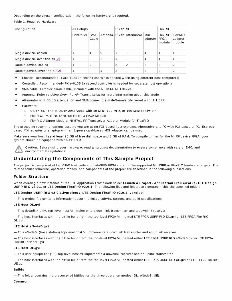
Depending on the chosen configuration, the following hardware is required.
Table 1. Required Hardware
Configuration All Setups USRP RIO FlexRIO
Controller SMA Cable
Antenna USRP Attenuator MXI adapter
FlexRIO FPGA module
FlexRIO adapter module
Single device, cabled 1 1 0 1 1 1 1 1
Single device, over-the-air[2] 1 - 2 1 - 1 1 1
Double device, cabled 1 2 - 2 2 2 2 2
Double device, over-the-air[2] 1 - 4 2 - 2 2 2
• Chassis: Recommended--PXIe-1085 (a second chassis is needed when using different host computers)
• Controller: Recommended--PXIe-8135 (a second controller is needed for separate host operation)
• SMA cable: Female/female cable, included with the NI USRP RIO device
• Antenna: Refer to Using Over-the-Air Transmission for more information about this mode
• Attenuator with 30 dB attenuation and SMA connectors male/female (delivered with NI USRP)
• Hardware:
o USRP RIO: one of USRP-294x/295x with 40 MHz, 120 MHz, or 160 MHz bandwidth
o FlexRIO: PXIe-7975/7976R FlexRIO FPGA Module
o FlexRIO Adapter Module: NI 5791 RF Transceiver Adapter Module for FlexRIO
The preceding recommendations assume you are using PXI-based host systems. Alternatively, a PC with PCI-based or PCI Express-based MXI adapter or a laptop with an Express card-based MXI adapter can be used.
Make sure your host has at least 20 GB of free disk space and 8 GB of RAM. To compile bitfiles for the NI RF device FPGA, your system should be equipped with 16 GB RAM.
Caution: Before using your hardware, read all product documentation to ensure compliance with safety, EMC, and environmental regulations.
Understanding the Components of This Sample Project The project is comprised of LabVIEW host code and LabVIEW FPGA code for the supported NI USRP or FlexRIO hardware targets. The related folder structure, operation modes, and components of the project are described in the following subsections.
Folder Structure
When creating a new instance of the LTE Application Framework select Launch a Project»Application Frameworks»LTE Design USRP RIO v2.0.1 or LTE Design FlexRIO v2.0.1. The following files and folders are created inside the specified folder:
LTE Design USRP RIO v2.0.1.lvproject / LTE Design FlexRIO v2.0.1.lvproject
— This project file contains information about the linked subVIs, targets, and build specifications.
LTE Host DL.gvi
— This downlink only, top-level host VI implements a downlink transmitter and a downlink receiver.
— The host interfaces with the bitfile build from the top-level FPGA VI, named LTE FPGA USRP RIO DL.gvi or LTE FPGA FlexRIO DL.gvi
LTE Host eNodeB.gvi
— This eNodeB, (base station) top-level host VI implements a downlink transmitter and an uplink receiver.
— The host interfaces with the bitfile build from the top-level FPGA VI, named either LTE FPGA USRP RIO eNodeB.gvi or LTE FPGA FlexRIO eNodeB.gvi
LTE Host UE.gvi
— This user equipment (UE) top-level host VI implements a downlink receiver and an uplink transmitter
— The host interfaces with the bitfile build from the top-level FPGA VI, named either LTE FPGA USRP RIO UE.gvi or LTE FPGA FlexRIO UE.gvi
Builds
— This folder contains the precompiled bitfiles for the three operation modes (DL, eNodeB, UE).
Common
— The common folder contains generic subVIs for host and FPGA that are used in but not limited to the LTE Application Frameworks, such as mathematical functions, type conversions, etc.
FlexRIO / USRP RIO
— These folders contain target-specific implementations of host and FPGA subVIs, which handle setting gain and frequency. These subVIs are in most cases adapted from the target-specific streaming sample project, either PXIe USRP RIO 120-160 MHz BW Single-Device Streaming for USRP RIO, or PXIe NI-579xR Streaming for FlexRIO/FlexRIO adapter module devices.
— These folders also contain the target specific top-level FPGA VI for the three operation modes: DL, eNodeB, and UE.
LTE v2.0.1
— This folder contains host and FPGA subVIs, which were specifically designed for the LTE Application Framework. The FPGA code is grouped into different folders that represent the part of the system where they are used, such as FPGA DL RX, FPGA DL TX, and so on.
Operation Modes
The LTE Application Framework offers three operation modes, including host code and associated FPGA code, which are depicted in Figure 2.
Downlink (DL):
— Establishes a downlink link in either a single-device setup or a double-device setup.
— Implements the downlink transmitter (DL TX) of a base station (eNodeB) and the downlink receiver (DL RX) of user equipment (UE).
— Top-level host VI: LTE Host DL.gvi
— Top-level FPGA VI: LTE FPGA FlexRIO DL.gvi or LTE FPGA USRP RIO DL.gvi
eNodeB:
— Provides the base station (eNodeB) side in a double-device setup.
— Implements the downlink transmitter (DL TX) and the uplink receiver (UL RX) of an eNodeB.
— Top-level host VI: LTE Host eNodeB.gvi
— Top-level FPGA VI: LTE FPGA FlexRIO eNodeB.gvi or LTE FPGA USRP RIO eNodeB.gvi
UE:
— Provides the user equipment (UE) side in a double-device setup
— Implements the downlink receiver (DL RX) and the uplink transmitter (UL TX) of a UE
— Top-level host VI: LTE Host eNodeB.gvi
— Top-level FPGA VI: LTE FPGA FlexRIO UE.gvi or LTE FPGA USRP RIO UE.gvi
Figure 2 System Configurations (Host and Associated FPGA Code)
The downlink (DL) operation mode can be used either in a single-device setup or in a double-device setup. The eNodeB/UE operation modes require a double-device setup.
Components
Figure 3 and Figure 4 show the block diagram of the system in the previously described operation modes.
Figure 3 Block diagram of the system in DL operation mode (single-device setup)
Figure 4 Block diagram of the system in eNodeB/UE operation mode (double-device setup)
The components shown in the figures above perform the following tasks:
• UDP read: Reads data, provided by an external application, from a UDP socket. The data is used as payload data in the transport block (TB). This data is then encoded and modulated as an LTE downlink (DL) signal by the downlink transmitter (DL TX PHY).
• UDP write: Writes the payload data, which was received and decoded from the LTE downlink (DL) signal by the downlink receiver (DL RX PHY), to a UDP socket. The data can then be read by an external application.
• MAC TX: A simple MAC implementation that adds a header to the transport block (TB) containing the number of payload bytes. The header is followed by the payload bytes, and the remaining bits of the TB are filled with padding bits.
• MAC RX: Disassembles the transport block (TB) and extracts the payload bytes.
• DL TX PHY: Physical layer (PHY) of the downlink (DL) transmitter (TX).
Encodes the physical channels and creates the LTE downlink signal as digital baseband I/Q data. This code includes encoding of the control channel (PDCCH), encoding of the data channel (PDSCH), resource mapping, and OFDM modulation.
• DL RX PHY: Physical layer (PHY) of the downlink (DL) receiver (RX).
Demodulates the LTE downlink signal and decodes the physical channels. This code includes primary synchronization sequence (PSS)-based synchronization, orthogonal frequency-division multiplexing (OFDM) demodulation, resource demapping, channel estimation and equalization, decoding of the control channel (PDCCH), and decoding of the data channel (=shared channel, PDSCH).
• UL TX PHY: Physical layer (PHY) of the uplink (UL) transmitter (TX).
Encodes the physical channels and creates the LTE uplink signal as digital baseband I/Q data. This code includes encoding of the data channel (=shared channel, PUSCH), resource mapping, and OFDM modulation.
• DL RX PHY: Physical layer (PHY) of the uplink (UL) receiver (RX).
Demodulates the LTE downlink signal and decodes the physical channels. This code includes OFDM demodulation, resource demapping, channel estimation and equalization, and decoding of the data channel (=shared channel, PUSCH).
• SINR calculation: Calculates the signal-to-interference-noise-ratio (SINR) based on the channel estimation that was used for PDSCH decoding. Channel estimation is either based on cell-specific reference signals (CRS), or on UE-specific reference signals (UERS).
• Rate adaptation: Sets the modulation and coding scheme (MCS) depending on the measured/reported signal-to-interference-noise-ratio (SINR). This keeps the block error rate (BLER) of the PDSCH decoding low.
• Feedback generation: Creates a feedback message that contains the measured subband and wideband SINR, as well as the ACK/NACK information (=CRC result of the PDSCH decoding) of the previously received radio frame.
• Feedback evaluation: Extracts the subband and wideband SINR, as well as the ACK/NACK information from the feedback message.
Statement of Compliance and Deviations
The LTE Application Framework implements parts of the 3GPP-LTE release 10 downlink and uplink physical layer transmitter and receiver. To reduce the complexity of this application framework, the following settings are fixed and can only be changed by modifying the design:
• 20 MHz bandwidth
• For TDD operation: Uplink (UL)/Downlink (DL) configuration 5, special subframe configuration 5
• Normal cyclic prefix
• Resource mapping for two TX antennas (only first antenna used)
• Downlink:
o Primary synchronization signals (PSS) only once per radio frame
(10 ms periodicity instead of 5 ms periodicity)
o Proprietary downlink control information (DCI) message format and length, PDCCH format 1 (CFI = 1)
o No secondary synchronization signals (SSS), physical broadcast channel (PBCH), physical control format indicator channel (PCFICH), or physical hybrid ARQ indicator channel (PHICH)
• Uplink:
o OFDMA is used for wideband modulation instead of SC-FDMA
o No physical random access channel (PRACH)
o No physical uplink control channel (PUCCH)
For more details, refer to the LTE Application Framework White Paper.
Running This Sample Project in a Single-Device Configuration This section describes how to run the LTE Application Framework using an RF loopback configuration with a single NI USRP RIO or FlexRIO device. This corresponds to the single device use case shown in Figure 1.
Configuring the Hardware
Depending on the available hardware, follow the steps of either Configuring the NI USRP RIO or Configuring the FlexRIO.
Configuring the NI USRP RIO
1. Ensure the USRP RIO device is properly connected to the host system running LabVIEW.
2. Create the RF loopback configuration using one RF cable and attenuator:
• Connect the cable to RF0/TX1.
• Connect the 30 dB attenuator to the other end of the cable.
1. Ensure the FlexRIO FPGA module with an attached FlexRIO adapter module is properly installed in the PXI Express chassis containing the embedded controller that is used as the host system running LabVIEW.
2. Create an RF loopback configuration by connecting the TX of the NI 5791 with the RX of the NI 5791. For this loopback connection, no external attenuator is needed, since the FlexRIO adapter module RX IN port is designed to handle the output power provided by the FlexRIO adapter module TX OUT port.
3. Power on the PXI chassis.
Figure 6 FlexRIO Hardware Configuration
Using Over-the-Air Transmission
The configuration for over the air transmission is similar to the cabled setup. Cables are replaced by antennas suitable for the selected channel center frequency and system bandwidth.
Caution Read the product documentation for all hardware components, especially the NI RF devices before using the system.
NI USRP and FlexRIO devices are not approved or licensed for transmission over the air using an antenna. As a result, operating those products with an antenna may violate local laws. Ensure that you are in compliance with all local laws before operating this product with an antenna.
Running the LabVIEW Host Code
The single-device hardware configuration uses the downlink only host variant of the LTE Application Framework (LTE Host DL.gvi), which implements a downlink transmitter and a downlink receiver.
Starting the System
Ensure the LabVIEW Communications System Design Suite and the LTE Application Framework are installed on your system.
Installation is started by running setup.exe from the provided installation media. Follow the installer prompts to complete the installation process.
1. Launch LabVIEW Communications System Design Suite, by selecting LabVIEW Communications 2.0 from the Start menu.
2. From the Project Templates on the Launch a Project tab, select Project Application Frameworks » LTE Design... to launch the project.
• Select "LTE Design USRP RIO v2.0.1" if you are using a USRP RIO device
• Select"LTE Design FlexRIO v2.0.1" if you are using a FlexRIO device.
3. Within that project, open the LabVIEW top-level host VI in the Downlink only variant, LTE Host DL.gvi. The panel of this VI is shown in Figure 7.
4. Set the RIO Device to the alias of the RIO device connected to your system. You can use NI Measurement & Automation Explorer (MAX) to get the RIO alias for your device.
5. Set USRP bandwidth to the bandwidth which matches your USRP RIO device. You can ignore this setting for a FlexRIO device.
6. Click the Run button, , on the LabVIEW host VI.
• If successful, the FPGA Ready indicator lights.
• If you receive an error, check if your RIO device is connected properly.
7. Set eNBTX Frequency [Hz] to a frequency supported by your NI USRP RIO or FlexRIO device, as shown in Table 1.
8. Set UERX Frequency [Hz] to the same value
9. Enable the eNB Transmitter, which implements a Downlink Transmitter, by setting the switch control to On.
• If successful, the eNB TX Active indicator lights.
10. Enable the UE Receiver, which implements a Downlink Receiver, by setting the Switch control to On.
• If successful, the UE RX Active indicator lights.
Figure 7 Front panel of LTE Host DL.gvi (downlink only host variant)
Table 2 Supported frequency ranges of NI USRP and FlexRIO/FAM models
NI Hardware model Supported frequency range
USRP-2940R/2950R 50 MHz to 2.2 GHz
USRP-2942R/2952R 400 MHz to 4.4 GHz
USRP-2943R/2953R 1.2 GHz to 6 GHz
USRP-2944R/2954R 10 MHz to 6 GHz
PXIe-7975R/7976R and NI 5791 200 MHz to 4.4 GHz
Verify That the System is Running as Expected
If the system is running as expected, the downlink signal generated by the transmitter is correctly received and decoded by the receiver. In this case, the host panel should appear as shown in Figure 8 and Figure 9.
Basic Tab
• TX Power spectrum—Spectrum matches the resource block allocation configured by the control Resource Block Allocation (4 PRB/bit)
• RX Power spectrum—Spectrum matches the TX power spectrum
• Sync Found—Constantly on, indicating sync success
Note: Sync success is a prerequisite for correct PDCCH (and PDSCH) reception and decoding.
• PDSCH Constellation—Clean and stable QPSK or QAM constellation. The modulation depends on the modulation and coding scheme that are configured by the MCS control on the eNB Transmit side. This graph indicates whether the PDSCH subcarriers were received correctly.
• Throughput—Constant green curve; constant value for PDSCH (CRC ok)
o No red portions in the curve; value PDSCH (CRC ok) equals value PDSCH (overall)
o Indicates correct PDSCH channel decoding without CRC errors
Advanced Tabs
• PDCCH Constellation—Clean and stable QPSK constellation (=allocated PDCCH subcarriers) with an additional dot in the origin (=unallocated PDCCH subcarriers). The graph indicates correct reception of the PDCCH subcarriers.
• PDCCH Received DCI Message—Valid flag is constantly on.
o MCS and Resource Block Allocation (4 PRB/bit) match the equally named controls on the eNB Transmitter side. This indicator shows whether PDCCH subcarrier data was received correctly.
Note: Correct PDCCH reception and decoding is a prerequisite for PDSCH reception and decoding.
• UE Failure / Block Error Rate (BLER)
o The Sync value is constantly zero.
o The PDCCH value is constantly zero.
o The PDSCH value is constantly zero.
Note: Sync success is a prerequisite for correct PDCCH (and PDSCH) reception and decoding. Correct PDCCH reception and decoding is a prerequisite for PDSCH reception and decoding. Correct PDSCH reception and decoding is a prerequisite for error-free data exchange.
• Channel Estimation—
o Normalized Amplitude: If using a cabled setup: flat curve around 0 as shown in Figure 9; if using an over-the-air setup: any curve (highs and lows indicate a frequency-selective channel caused by multipath fading)
o Phase: If using a cabled setup: saw tooth curve (straight line, wrapping two times) as shown in Figure 9 (indicating that FFT cuts slightly into the cyclic prefix)
Figure 8 Front panel of LTE Host DL.gvi / Basic Tab when running successfully
Figure 9 Front panel of LTE Host DL.gvi / Advanced Tab when running successfully
Running Video Streaming
The previous section described how to use the downlink host variant of the LTE Application Framework (LTE Host DL.gvi) to establish a LTE downlink link between the transmitter and the receiver. A basic MAC implementation allows for packet-based data exchange of user-defined payload data. The payload data can be provided to the host using UDP as shown in Figure 10. You can use any program capable of transmitting UDP data as data source. Similarly, you can use any program capable of receiving UDP data as a data sink.
The LTE Application Framework allows you to transmit video streams if you use a video streaming application as data source and a video player as data sink. For example, you can use the VLC media player, which is available at www.videolan.org.
Figure 10 Data streaming to/from the system using UDP (downlink-only operation mode)
Start Video Stream Transmitter
1. Start cmd.exe and change the directory to the VLC installation directory.
2. Start the VLC application as a streaming client with the following command:
vlc.exe --repeat ";PATH_TO_VIDEO_FILE” :sout=#std{access=udp{ttl=1},mux=ts,dst=127.0.0.1:50000} where PATH_TO_VIDEO_FILE should be replaced with the location of the video that should be used.
Port 50.000 is the default UDP Receive Port. For ease of use, you can also save this command line to a batch file, for example, Stream Video LTE.bat.
Start Video Stream Receiver
1. Start cmd.exe and change the directory to the VLC installation directory.
2. Start the VLC application as a streaming client with the following command:
vlc.exe udp://@:60000
Port 60.000 is the default UDP Transmit Port. For ease of use, you can also save this command line to a batch file, e.g. Play Video LTE.bat.
Description of the Controls and Indicators on the Host Panel
This section provides information about how to use the controls and how to interpret the graphs and indicators that are available on the host panel.
Application Settings
Set these parameters prior to running the gvi. Changes are only applied after stopping and restarting the gvi.
Parameter Description
RIO Device The RIO address of the RF hardware device.
Reference Clock Source
Configures the Reference Clock source used for the transceiver chain.
• Internal: Device internal clock
• REF IN / ClkIn: Clock input at the RF device (rear connector pane of USRP RIO, front connector pane for NI 579x devices)
• PXI_CLK: Backplane clock from the PXI Chassis (NI 579x only)
• GPS: GPS module (NI RIO 295x devices only)
USRP Bandwidth The bandwidth of the RF hardware device. Applicable only for USRP RIO devices.
Basic Runtime Static Settings
These settings, located on the Basic tabs, can be changed without restarting the gvi. Value changes are applied when the corresponding transmitter or receiver chain is restarted using the associated Boolean control.
Parameter Description
eNB Transmitter Enables or disables the transmitter using the current configuration.
eNB TX Frequency [Hz] DL TX center frequency. The allowed range depends on the RF device used.
eNB Maximum RF TX Power [dBm]
Maximum RF transmit power (upper bound - achievable for a full scale complex sine wave (CW) signal).
Note: The actual time-domain RF transmit power depends on the configured resource allocation, and is typically at least 15 dB lower to allow for the OFDM PAPR backoff.
UE Receiver Enables or disables the receiver using the current configuration.
UE RX Frequency [Hz] DL RX center frequency. The allowed range depends on the RF device used.
Advanced Runtime Static Settings
These settings, located on the Advanced tabs, can be changed without restarting the gvi. Value changes are applied when the corresponding transmitter or receiver chain is restarted using the associated Boolean control.
Parameter Description
UDP Receive Port The UDP port the host monitors for incoming packets to be transferred to the FPGA PDSCH chain.
eNB TX RF Port (USRP)
Selects the RF port the DL TX is transmitted on (USRP RIO only).
eNB TX Frame Structure
Selects between frequency division duplex (FDD) and time division duplex (TDD) using subframe configuration 5 and special subframe configuration 5 (3GPP TS 36.211 §4).
eNB TX Cell ID Physical cell ID used for PSS, CRS, UERS sequence generation and PDCCH/PDSCH scrambling. [0...511]
Transmit IP Address
The IP address the UDP packets received from PDSCH are sent to.
UDP Transmit Port The UDP port the UDP packets received from PDSCH are sent to.
UE RX RF Port (USRP)
Selects the RF port the DL RX will be received from (USRP RIO only).
UE RX Frame Structure
Selects between FDD (frequency division duplex) and TDD (time division duplex) using subframe configuration 5 and special subframe configuration 5 (3GPP TS 36.211 §4).
UE RX Cell ID Physical cell ID used for PSS, CRS, UERS sequence generation and PDCCH/PDSCH scrambling. [0...511]
Runtime Dynamic Settings
These settings can be changed while the corresponding transmitter or receiver chain is running. Value changes are applied immediately.
Parameter Description
eNB TX DCI Downlink control information for the PDCCH content and the PDSCH transmission.
Active Enables or disables the transmission of PDCCH and PDSCH.
Resource Block Allocation Resource allocation given as bitmap, with each bit representing four physical resource blocks (DL resource allocation type 0, 3GPP TS 36.213 §7.1.6.1). The left-most bit represents the lowest resource block index.
MCS Modulation and coding scheme used for PDSCH transmission according to 3GPP TS 36.213 §7.1.7.
eNB TX UE Context UE specific parameters for DL transmission.
Use UERS If enabled, the DL transmitter feeds UE-specific reference signals into the PDSCH data stream. The usage of UERS is closely related to Transmission Mode 9 defined in the LTE standard 3GPP TS 36.213 §7.1.
Antenna Port The antenna port used for generating UERS. Range is 7...14, according to 3GPP TS 36.213 §7.1.
RNTI The radio network temporary identifier used for PDSCH scrambling and PDCCH CRC mask generation.
CCE Offset First control channel element to be used for PDCCH transmission, according to 3GPP TS 36.211 §6.8.1/.2.
eNB Timing Offset Changes the eNodeB timing (start of radio frame). Given in 30.72 MS/s.
Rate Adaptation If enabled, eNB TX MCS is automatically adapted to reported/measured Wideband SINR [dB] to handle channel quality fluctuations. The adaptation is calibrated so that the applied MCS produces approximately 5% to 10% BLER under current MCS conditions. Modify SINR Offset [dB] to achieve different values.
SINR Offset [dB] This value is effectively subtracted from the reported SINR before looking up the MCS in the adaptation table (for example, if a positive offset is configured, a higher reported SINR is required to adapt to a certain MCS to avoid block errors).
UE RX UE Context UE-specific parameters for DL reception. Use UERS If enabled, the DL receiver uses UE specific reference signals to equalize
PDSCH assigned I/Q samples. The usage of UERS is closely related to Transmission Mode 9, defined in the LTE standard 3GPP TS 36.213 §7.1.
Antenna Port The antenna port used for generating UERS for channel estimation. Range is 7...14 according to 3GPP TS 36.213 §7.1
RNTI The radio network temporary identifier used for PDSCH scrambling and PDCCH CRC mask checks.
CCE Offset First control channel element to be used for PDCCH reception, according to 3GPP TS 36.211 §6.8.1/.2.
Symbol-Nr (PDSCH) The OFDM symbol number (counting from 0 with symbol 0 being occupied by the PDCCH) used to display constellation data for PDSCH I/Q samples.
Throughput [Mbps] select Selects the used values for throughput calculation:
• PDSCH (overall): The total throughput scheduled by the eNodeB TX, regardless of CRC result.
• PDSCH (CRC ok): The actual achieved physical layer throughput which was decoded successfully.
• User data (to UDP): The higher layer throughput (from/to the UDP stream) after removing the padding.
UE AGC Enables or disables the automated gain control on the receiver side. If enabled, the analog RX gain of the RF device is automatically configured within its valid range to meet a target range for the baseband input signal power.
UE Manual Gain Value [dB] Controls the analog RX gain if UE AGC is switched off.
Graphs and Indicators
The indicators on the front panel represent the state of the target device and show information about ongoing transfers.
Parameter Description
FPGA ready Indicates that the FPGA bitfile has been downloaded and that the device has been initialized and is ready for configuration. Initialization can take up to 20 seconds.
eNB TX Active Indicates that all eNB TX control configurations have been applied and the transmitter is running.
eNB RF TX Power [dBm]
Actual eNB RF transmit power, in dBm.
eNB Coerced Max RF TX Power [dBm]
Indicates the coerced value actually used as maximum RF transmit output power after applying the device capabilities (with range and resolution limitations) to the configured eNB Maximum RF TX Power [dBm].
eNB TX Power Spectrum
Shows the power spectrum of the DL TX baseband signal transferred to the RF.
Data Transfer In Indicates that the configured UDP stream is receiving data on the configured Receive Port.
Packet Loss In Indicates that the system is losing UDP data due to overload, which can occur when data inflow from UDP port is higher than the configured PDSCH throughput.
eNB TX IFFT Output Clipped
Indicates a numeric overflow after the IFFT.
eNB Baseband TX Power [dBFS]
Actual eNB baseband transmit power level [baseband output power level], in dB full scale.
UE RX Active Indicates that all UE RX control configurations have been applied and the receiver is running.
Sync Found Indicates that the synchronization module has successfully detected and synchronized to a DL RX signal.
UE Frequency Offset [Hz]
The estimated and compensated frequency offset detected in the RX signal.
UE RF RX Power [dBm]
The measured time domain input power at the RX RF port.
UE ADC Values Clipped
Indicates a numeric overflow at the ADC output. An overflow can occur when the analog RX RF gain is too high or the receiver power level is too high.
UE DDC Values Clipped
Indicates a numeric overflow at the output of the digital downconversion block. An overflow can occur when the analog RX RF gain is too high or the receive power level is too high.
UE Coerced Gain [dB] The actual used analog RX RF gain either set by AGC ( if enabled) or by UE Manual Gain Value [dB].
UE Baseband RX Power [dBFS]
The measured baseband input power level, in dB full scale.
UE RX Power Spectrum
Shows the power spectrum of the DL RX baseband signal received from RF. If synchronization is successful, frequency offset compensation is applied.
PDSCH Constellation Constellation of RX I/Q samples allocated for PDSCH transmission after equalization. Only samples for the configured OFDM Symbol-Nr (PDSCH) are displayed.
Wideband SINR [dB] The estimated SINR over the full 20 MHz band using cell-specific reference signals.
Subband SINR [dB] The estimated SINR for each subband occupying 8 PRBs. Comparable to Reporting Mode 3-0 in 3GPP TS 36.213 §7.2.1. Usage of CRS or UERS for estimation depends on the Use UERS switch setting in UE RX System Parameters.
Throughput [Mbps] Numerical and graphical indication of scheduled, successfully decodable, and actually used channel capacity.
• PDSCH (overall): The total throughput scheduled by the eNodeB TX regardless of the CRC result.
• PDSCH (CRC ok): The actual achieved physical layer throughput that was decoded successfully.
• User data (to UDP): The higher layer throughput (from/to the UDP stream) after removing the padding.
Data Transfer Out Indicates that the configured UDP stream is sending data to the configured Transmit IP Address using Transmit Port.
Packet Loss Out Indicates that the system is losing UDP data caused by overload, which can occur when data inflow from the PDSCH is higher than UDP throughput.
PDCCH Constellation Constellation of RX I/Q samples allocated for PDCCH transmission after equalization.
UE Failure / Block Error Rate (BLER)
Numerical and graphical display of error rates for synchronization detection and PDCCH and PDSCH decoding.
Channel Estimation Graphical representation of the normalized channel amplitude and phase estimated on the cell specific reference signals.
PDCCH Received DCI Message
Array of decoded and interpreted downlink control information messages received on PDCCH and applied to PDSCH decoding. Each element corresponds to a DL subframe.
Running This Sample Project in Double-Device Setup The section describes how to run the LTE Application Framework using an RF loopback configuration with either two NI USRP RIO or two FlexRIO devices. This configuration corresponds to the double-device setups shown in Figure 1. The devices can be either connected to the same host computer or to different host computers.
Configuring the Hardware
Depending on the available hardware, follow the steps of either Configuring the NI USRP RIO or Configuring FlexRIO Setup.
Configuring the NI USRP RIO Setup
1. Ensure both NI USRP devices are properly connected to the host system running LabVIEW.
2. Create an RF connection as shown in the following figure:
3. On station A, connect the cable to RF0/TX1.
4. Connect the other end of that cable to the 30 dB attenuator.
5. Connect the attenuator to RF1/RX2 on station B.
6. On station B, connect the cable to RF0/TX1.
7. Connect the other end of that cable to the 30 dB attenuator.
8. Connect the attenuator to RF1/RX2 on station A.
Figure 11 Cabled Connection of two NI USRP Devices
Configuring the FlexRIO Setup
1. Ensure that the FlexRIO FPGA module with an attached FlexRIO adapter module is installed in the PXI Express chassis containing the embedded controller that is used as the host system running LabVIEW.
2. Create an RF connection as shown in the following figure:
3. On device A, connect the cable to TX.
4. Connect the cable to RX on device B.
5. On device B, connect another cable to TX.
6. Connect the cable to RX on device A.
Figure 12 Cabled Connection of two FlexRIO Devices
Using Over-the-Air Transmission
The configuration for over the air transmission is similar to the cabled setup. Cables are replaced by antennas suitable for the selected channel center frequency and system bandwidth.
Caution Read the product documentation for all hardware components, especially the NI RF devices, before using the system.
NI USRP and FlexRIO devices are not approved or licensed for transmission over the air using an antenna. As a result, operating those products with an antenna may violate local laws. Ensure that you are in compliance with all local laws before operating this product with an antenna.
Running the LabVIEW Host Code
Depending on the selected host applications, different operation modes are possible:
• One device acts as eNodeB by running Host eNodeB.gvi (downlink transmitter and uplink receiver) and the other device acts as UE by running Host UE.gvi (downlink receiver and uplink transmitter).
• Alternatively, both devices can act as downlink transmitters and receivers by running the downlink only host variant (LTE Host DL.gvi) on both host computers.
This section describes how to run the system in the eNodeB/UE operation mode. The downlink only operation mode using a double-device setup is not further described here because it is similar to the downlink only operation mode using a single-device setup that is described in the previous chapter.
Starting the System
On the eNodeB host computer
1. Launch LabVIEW Communications System Design Suite by selecting LabVIEW Communications 2.0 from the Start menu.
2. From the Project Templates on the Launch a Project tab, select Project Application Frameworks » LTE Design to launch the project.
• Select LTE Design USRP RIO v2.0.1 if you are using a USRP device.
• Select LTE Design FlexRIO v2.0.1 if you are using a FlexRIO device.
3. Within that project, open the LabVIEW top-level host VI for the eNodeB operation mode, LTE Host eNodeB.gvi. The front panel of this VI is shown in Figure 13.
4. Set USRP bandwidth to the bandwidth which matches your USRP RIO device. You can ignore this setting for a FlexRIO device.
5. Set the RIO Device to the alias of the RIO device connected to your system. You can use NI Measurement & Automation Explorer (MAX) to get the RIO alias for your device.
6. Click the Run button, , on the LabVIEW host VI.
• If successful, the FPGA Ready indicator lights.
• If you receive an error, check whether your RIO device is connected properly.
Figure 13 Front panel of LTE Host eNodeB.gvi
On the UE Host Computer
7. Launch LabVIEW Communications System Design Suite by selecting LabVIEW Communications 2.0 from the Start menu.
8. From the Project Templates on the Launch a Project tab, select Application Frameworks » LTE Design to launch the project.
• Select LTE Design USRP RIO v2.0.1 if you are using a USRP RIO device.
• Select LTE Design FlexRIO v2.0.1 if you are using a FlexRIO device.
9. Within that project, open the LabVIEW top-level host VI for the UE operation mode, LTE Host UE.gvi.
The front panel of this VI is shown in Figure 14.
10. Set the RIO Device to the alias of the RIO device connected to your system. You can use NI Measurement & Automation Explorer (MAX) to get the RIO alias for your device.
11. Set USRP bandwidth to the bandwidth which matches your USRP RIO device. You can ignore this setting for a FlexRIO device.
12. Click the Run button on the LabVIEW host VI.
• If successful, the FPGA Ready indicator lights.
• If you receive an error, check whether your RIO device is connected properly.
Figure 14 Front panel of LTE Host UE.gvi
On the eNodeB Host Computer
13. Set the control eNBTX Frequency [Hz] to a frequency supported by your USRP RIO or FlexRIO device, refer to Table 1.
14. Enable the eNB Transmitter(implementing a Downlink Transmitter) by setting the switch control to On.
• If successful, the eNB TX Active indicator lights.
On the UE Host Computer
15. Set the control UERX Frequency [Hz] to the same value as you have chosen for eNB TX Frequency [Hz].
16. Enable UE Receiver(implementing a Downlink Receiver) by setting the switch control to On.
• If successful, the UE RX Active indicator lights.
17. Set the control UETX Frequency [Hz] to a frequency supported by your USRP RIO or FlexRIO device, see Table 1.
18. Enable the UE Transmitter(implementing an Uplink Transmitter) by setting the switch control to On.
• If successful, the UE TX Active indicator lights.
On the eNodeB Host Computer
19. Set the control eNBRX Frequency [Hz] to the same value as you have chosen for UE TX Frequency [Hz].
20. Enable eNB Receiver, which implements an uplink receiver, by setting the switch control to On.
• If successful, the eNB RX Active indicator lights.
Verify That the System is Running as Expected
If the system is running as expected, all necessary steps as illustrated in Figure 15 were completed successfully. As a result, the indicators and graphs on the host panel should look similar to the host panels shown in Figure 16, Figure 17, and Figure 18.
Figure 15 Establishing a downlink and uplink connection between eNodeB and UE
eNodeB Transmits Downlink
"eNB Transmitter” side / "Basic” Tab
1. Graph eNBTX Power spectrum:
Spectrum matches the resource block allocation configured by the control "eNB TX Resource Block Allocation [4 PRB/bit]";
UE Receives Downlink
"UE Receiver” side / "Basic” Tab
2. Graph UERX Power spectrum:
Spectrum matches the eNB TX power spectrum
3. Indicator Sync Found:
Constantly on, indicating sync success
Note: Sync success is a prerequisite for correct PDCCH (and PDSCH) reception and decoding.
4. Graph PDSCH Constellation:
Shows a clean QPSK or QAM constellation (modulation depends on the modulation and coding scheme, which is configured on the eNB Transmitter side by the control "eNB TX MCS";)
5. Graph Throughput
Constant green curve; constant value for PDSCH (CRC ok)
No red portions in the curve; the value PDSCH (CRC ok) equals the value PDSCH (overall)
Indicates correct PDSCH channel decoding without CRC errors
"UE Receiver” side / "Advanced” Tab
6. Graph PDCCH Constellation:
Clean and stable QPSK constellation (=allocated PDCCH subcarriers) with an additional dot in the origin (=unallocated PDCCH subcarriers)
Indicates correct reception of the PDCCH subcarrier data
7. Indicator PDCCH Received DCI Message:
"Valid"; flag is constantly on
"MCS"; and "Resource Block Allocation (4 PRB/bit)"; match the equally named controls on the "eNB Transmitter"; side
Note: Correct PDCCH reception and decoding is a prerequisite for PDSCH reception and decoding
8. Graph UE Failure / Block Error Rate (BLER):
Value "Sync"; is constantly zero
Value "PDCCH"; is constantly zero
Value "PDSCH"; is constantly zero
Note: Sync success is a prerequisite for correct PDCCH (and PDSCH) reception and decoding. Correct PDCCH reception and decoding is a prerequisite for PDSCH reception and decoding. Correct PDSCH reception and decoding is a prerequisite for error-free data exchange.
9. Graph Channel Estimation:
"Normalized Amplitude";: In case of cabled setup: flat curve around 0 as shown in Figure 17; in case of over-the-air setup: any curve (highs and lows indicate a frequency-selective channel caused by multipath fading)
"Phase";: In case of cabled setup: saw tooth curve (straight line, wrapping two times) as shown in Figure 17 (indicating that FFT cuts slightly into the cyclic prefix)
UE transmits Uplink
"UE Transmitter” side / "Basic” Tab
10. Graph UETX Power spectrum:
Spectrum matches the resource block allocation configured by the control " UE TX Resource Block Allocation (4 PRB/bit)";
eNodeB receives Uplink
"eNB Receiver” side / "Basic” Tab
11. Graph eNBRX Power spectrum:
Spectrum matches the UE TX power spectrum
12. Graph eNB Failure / Block Error Rate (BLER):
Constantly zero indicating correct PUSCH reception without CRC errors
13. Graph Reported DL Block Error Rate:
Constantly zero indicating correct PDSCH reception without CRC errors on the UE Receiver side
Note: displayed value matches the value "PDSCH"; in the "UE Failure / Block Error Rate (BLER)"; graph on the "Advanced"; tab on the UE Receiver side
14. Indicator PUSCH throughput indicator:
Non-zero value (the actual value is matching the theoretical data rate for the combination of MCS and resource block allocation which was set on the UE TX side)
15. Indicator Reported DL ACK/NACK:
Values "ACK, ACK, ..., ACK"; in case of FDD frame structure ("ACK, DTX, DTX, ACK, ..., ACK"; in case of TDD frame structure), indicating correct PDSCH reception without CRC errors on the UE Receiver side
16. Indicator The Radio Frame Number:
Value is rapidly increasing
"eNB Receiver” side / "Advanced” Tab
17. Graph PUSCH Constellation:
Shows a clean QPSK or QAM constellation (modulation depends on the modulation and coding scheme, which is configured on the UE Transmitter side by the control "UE TX MCS";)
Figure 16 Front panel of LTE Host eNodeB.gvi / Basic Tabs when running successfully
Figure 17 Front panel of LTE Host eNodeB.gvi / Advanced Tabs when running successfully
Figure 18 Front panel of LTE Host UE.gvi / Basic Tabs when running successfully
Figure 19 Front panel of LTE Host UE.gvi / Advanced Tabs when running successfully
Running Video Streaming
The previous section described how to use the LTE Application Framework with the double-device setup in eNodeB/UE configuration for establishing a LTE downlink link between the eNodeB device and the UE device. A basic MAC implementation allows for packet-based data exchange of user data between eNodeB and UE. The user data can be provided to the host using UDP as shown in Figure 10. Any program capable of transmitting UDP data can be used as a data source. Similarly, any program capable of receiving UDP data can be used as a data sink.
Figure 20 Data streaming to/from the system using UDP (eNodeB/UE operation mode)
As described in the Running This Sample Project in a Single-Device Configuration section, the VLC media player can be used to stream video data. Please refer to this section for detailed instructions. The commands as described in Start Video Stream Transmitter (Stream Video LTE.bat) need to run on the host computer running the LTE Host eNodeB.gvi. The commands as described in Start Video Stream Transmitter (Play Video LTE.bat) need to run on the host computer running the LTE Host UE.gvi.
Description of the Controls and Indicators on the Host Panel
This section provides information about how to use the controls and how to interpret the graphs and indicators which are available on the host panel.
eNodeB
Application Settings
These settings need to be set prior to running the gvi. Changes will only be applied after stopping and restarting the gvi.
Parameter Description
RIO Device The RIO address of the RF hardware device.
Reference Clock Source
Configures the Reference clock source used for the transceiver chain.
• Internal: device internal clock
• REF IN / ClkIn: Clock input at the RF device (rear connector pane of USRP RIO devices, front connector pane of NI 579x devices)
• PXI_CLK: Clock of the PXI Chassis (NI 579x only)
• GPS: GPS module (USRP RIO 295x only)
USRP Bandwidth The bandwidth of the RF hardware device. Applicable only for USRP RIO devices.
Basic Runtime Static Settings
These settings, placed on the Basic tabs, can be changed without restarting the gvi. Value changes are applied when the corresponding transmitter or receiver chain is restarted using the associated switch control (Off » On).
Parameter Description
eNB Transmitter Enables or disables the transmitter using the current configuration.
eNB TX Frequency [Hz] DL TX center frequency. The allowed range depends on the RF device used.
eNB Maximum RF TX Power [dBm]
Maximum RF transmit output power (upper bound - achievable for a full scale complex sine wave (CW) signal).
Note: The actual time-domain RF transmit power depends on the configured resource allocation, and is typically at least 15 dB lower to allow for the OFDM PAPR backoff.
eNB Receiver Enables or disables the receiver using the current configuration.
eNB RX Frequency [Hz] UL RX center frequency. The allowed range depends on the RF device used.
Advanced Runtime Static Settings
These settings, placed on the Advanced tabs, can be changed without restarting the gvi. Value changes are applied when the corresponding transmitter or receiver chain is restarted using the associated switch control (Off » On).
Parameter Description
UDP Receive Port The UDP port the host monitors for incoming packets to be transferred to the FPGA PDSCH chain.
eNB TX RF Port (USRP)
Selects the RF port where the DL TX is transmitted (USRP RIO only).
eNB TX Frame Structure
Selects between frequency division duplex (FDD) and time division duplex (TDD) using subframe configuration 5 and special subframe configuration 5 (3GPP TS 36.211 §4).
eNB TX Cell ID Physical cell ID used for PSS, CRS, UERS sequence generation and PDCCH/PDSCH scrambling. [0...511]
eNB RX RF Port Selects the RF port the UL RX will be received from (USRP RIO only).
eNB RX Frame Structure
Selected between FDD (frequency division duplex) and TDD (time division duplex) using subframe configuration 5 and special subframe configuration 5 (3GPP TS 36.211 §4).
eNB RX Cell ID The physical Cell ID used for PUSCH scrambling.
Runtime Dynamic Settings
These setting can be changed while the corresponding transmitter or receiver chain is running. Value changes are applied immediately.
Parameter Description
eNB TX DCI Downlink control information for the PDCCH content and the PDSCH transmission.
Active Enables or disables the transmission of PDCCH and PDSCH.
Resource Block Allocation
Resource allocation given as bitmaps, with each bit representing four physical resource blocks (DL resource allocation type 0, 3GPP TS 36.213 §7.1.6.1). The left-most bit represents the lowest resource block index.
MCS Modulation and coding scheme used for PDSCH transmission, according to 3GPP TS 36.213 §7.1.7.
eNB TX UE Context UE specific parameters for DL transmission.
Use UERS If enabled, the DL transmitter feeds UE-specific reference signals into the PDSCH data stream. The usage of UERS is closely related to Transmission Mode 9 defined in the LTE standard 3GPP TS 36.213 §7.1.
Antenna Port The antenna port used for generating UERS. Range is 7...14, according to 3GPP TS 36.213 §7.1
RNTI The radio network temporary identifier used for PDSCH scrambling and PDCCH CRC mask generation.
CCE Offset First control channel element to be used for PDCCH transmission, according to 3GPP TS 36.211 §6.8.1/.2.
eNB Timing Offset Changes the eNodeB timing (start of radio frame). Given in 30.72 MS/s.
Rate Adaptation If enabled, eNB TX MCS is automatically adapted to reported/measured Wideband SINR [dB] to handle channel quality fluctuations. The adaptation is calibrated so that the applied MCS produces about 5% to 10% BLER under current MCS conditions. Modify SINR Offset [dB] to change these values.
SINR Offset [dB] This value is effectively subtracted from the reported SINR before looking up the MCS in the adaptation table (i.e. if a positive offset is configured, a higher reported SINR is required to adapt to a certain MCS to avoid block errors).
eNB RX DCI Parameters for reception of PUSCH.
Active Enables or disables the reception of the PUSCH.
MCS Modulation and coding scheme used for PUSCH reception, according to 3GPP TS 36.213 §7.1.7.
Resource Block Allocation
Resource allocation for PUSCH given as a bitmap, with each bit representing 4 physical resource blocks (DL resource allocation type 0, 3GPP TS 36.312 §7.1.6.1). The leftmost bit represents lowest resource block index.
eNB RX UE Context UE-specific parameters for UL reception.
RNTI The radio network temporary identifier used for PUSCH scrambling.
SRS Configuration The configuration used for receiving sounding reference signals.
SRS Enabled If TRUE, the SRS location is reserved as last symbol in each UL subframe (FDD, TDD) and the last 2 symbols in each special subframe (TDD), according to 3GPP TS 36.211 §5.5.3.3: FDD: srs-SubframeConfig = 0, TDD: srs-SubframeConfig = 7.
SRS Subframe Allocation
This bitmap determines the subframes actually used for SRS transmission. Periodicity of 10, and the leftmost bit represents subframe 0.
Transmission Comb
Parameter transmissionComb k_TC determining if even (0) or odd (1) subcarriers are used for SRS transmission/reception. See also 3GPP TS 36.211 §5.5.3.2.
Symbol-Nr (PUSCH) The OFDM symbol number used for displaying constellation data for PUSCH IQ samples.
eNB AGC Enables or disables the automated gain control on the receiver side. If enabled, the analog RX gain of the RF device will be automatically configured within its valid range to meet a target range for the baseband receive power.
eNB Manual Gain Value [dB]
Controls the analog RX gain if eNB AGC is switched off.
Graphs and Indicators
The indicators on the front panel represent the state of the target device and show information about ongoing transfers.
Parameter Description
FPGA ready Indicates that the FPGA bitfile has been downloaded and that the device has been initialized and is ready for configuration (initialization can take up to 20 seconds).
eNB TX Active Indicates that all eNB TX control configurations have been applied and the transmitter is running.
eNB RF TX Power [dBm]
Actual eNB RF transmit power, in dBm.
eNB Coerced Max RF TX Power [dBm]
Indicates the coerced value actually used as maximum RF transmit output power level after applying the device's capabilities (range and resolution limitations apply) to the configured eNB Maximum RF TX Power [dBm].
eNB TX Power Spectrum
Indicates the power spectrum of the DL TX baseband signal transferred to the RF.
Data Transfer In Indicates that the configured UDP stream is receiving data on the configured Receive Port.
Packet Loss In Indicates that the system is losing UDP data due to overload. Data inflow from UDP port is higher than the configured PDSCH throughput.
eNB TX IFFT Output Clipped
Indicates a numeric overflow after the IFFT.
eNB Baseband TX Power [dBFS]
Actual eNB baseband transmit power level [baseband output power level] in dB full scale.
eNB RX Active Indicates that all eNB RX control configurations have been applied and the receiver is running.
eNB RF RX Power [dBm]
The measured time domain receive power at the RX RF port.
eNB ADC Values Clipped
Indicates a numeric overflow at the ADC output. Overflows can be caused when the analog RX RF gain is too high or the receive power level is too high.
eNB DDC Values Clipped
Indicates a numeric overflow at the output of the digital downconversion block. Overflows can be caused when the analog RX RF gain is too high or the receive power level is too high.
eNB Coerced Gain [dB]
The actual used analog RX RF gain either set by AGC, if enabled, or by UE Manual Gain Value [dB].
eNB Baseband RX Power [dBFS]
The measured baseband receive power level, in dB full scale.
eNB RX Power Spectrum
Indicates the power spectrum of the UL RX baseband signal received from RF.
PUSCH Throughput [Mbps]
The achieved throughput on the PUSCH channel.
eNB Failure / Block Error Rate (BLER)
Graphical display of the PUSCH reception block error rate.
Reported DL ACK/NACK
This array displays the latest received DL ACK/NACK report from the UE side.
Radio Frame Number The number of the latest successfully received report ranging from 0...1023.
Reported DL Block Error Rate
Graphical and numerical representation of the DL receiver block error rate on the UE side reported back to the eNodeB.
Reported Subband SINR [dB]
The reported SINR for each subband occupying 8 PRBs. Comparable to Reporting Mode 3-0 in 3GPP TS 36.213 §7.2.1. Usage of CRS or UERS for estimation depends on the Use UERS switch setting in UE RX System Parameters on the UE side.
Reported Wideband SINR [dB]
The reported SINR over the full 20 MHz band using cell specific reference signals.
PUSCH Constellation Constellation of RX IQ samples allocated for PUSCH transmission after equalization. Only samples for the configured OFDM Symbol-Nr (PUSCH) are displayed.
UE
Application Settings
You must set the application setting prior to running the gvi. Changes will only be applied after stopping and restarting the gvi.
Parameter Description
RIO Device The RIO address of the RF hardware device.
Reference Clock Source
Configures the Reference clock source used for the transceiver chain.
• Internal: device internal clock
• REF IN / ClkIn: Clock input at the RF device (rear connector pane of USRP RIO devices, front connector pane of the NI 579x)
• PXI_CLK: Clock of the PXI Chassis (NI 579x only)
• GPS: GPS module (USRP RIO 295x only)
USRP Bandwidth The bandwidth of the RF hardware device. Applicable only for USRP RIO devices.
Basic Runtime Static Settings
These settings, placed on the Basic tabs, can be changed without restarting the gvi. Value changes are applied when the corresponding transmitter or receiver chain is restarted using the associated switch control (Off » On).
Parameter Description
UE Transmitter Enables or disables the transmitter using the current configuration.
UE TX Frequency [Hz] UL TX center frequency. The allowed range depends on the RF device used.
UE Maximum RF TX Power [dBm]
Maximum RF transmit output power (upper bound - achievable for a full scale complex sine wave (CW) signal).
Note: The actual time-domain RF transmit power depends on the configured resource allocation and is typically at least 15 dB lower to allow for the OFDM PAPR backoff.
Timing Advance [samples]
The applied UL timing advance, i.e. the number of samples the UL TX is started earlier than the DL RX. Given in the 30.72 MS/s domain.
UE Receiver Enables or disables the receiver using the current configuration.
UE RX Frequency [Hz] DL RX center frequency. The allowed range depends on used RF device.
Advanced Runtime Static Settings
These settings, placed on the Advanced tabs, can be changed without restarting the gvi. Value changes are applied when the corresponding transmitter or receiver chain is restarted using the associated switch control (Off » On).
Parameter Description
UE TX RF Port (USRP)
Selects the RF port the UL TX will be transmitted on (USRP RIO only).
UE TX Frame Structure
Selects between FDD (frequency division duplex) and TDD (time division duplex) using subframe configuration 5 and special subframe configuration 5 (3GPP TS 36.211 §4).
UE TX Cell ID Physical cell ID used for PUSCH scrambling.
Transmit IP Address
The IP address the UDP packets received from PDSCH are sent to.
UDP Transmit Port
The UDP port the UDP packets received from PDSCH are sent to.
UE RX RF Port Selects the RF port the DL RX is received from (USRP RIO only).
UE RX Frame Structure
Selects between FDD (frequency division duplex) and TDD (time division duplex) using subframe configuration 5 and special subframe configuration 5 (3GPP TS 36.211 §4).
UE RX Cell ID Physical cell ID used for PSS, CRS, UERS sequence generation and PDCCH/PDSCH scrambling. [0...511]
Runtime Dynamic Settings
These settings can be changed while the corresponding transmitter or receiver chain is running. Value changes are applied immediately.
Parameter Description
UE TX DCI Parameters for transmission of PUSCH.
Active Enables or disables the transmission of the PUSCH.
MCS Modulation and coding scheme used for PUSCH transmission according to 3GPP TS 36.213 §7.1.7.
Resource Block Allocation
Resource allocation for PUSCH given as bitmap with each bit representing 4 physical resource blocks (DL resource allocation type 0, 3GPP TS 36.312 §7.1.6.1). The leftmost bit represents lowest resource block index.
UE TX UE Context UE-specific parameters for UL transmission.
RNTI The radio network temporary identifier used for PUSCH scrambling.
SRS Configuration The configuration used for transmitting the sounding reference signal.
SRS Enabled If TRUE, the SRS location is reserved as last symbol in each UL subframe (FDD, TDD) and last 2 symbols in each special subframe (TDD), according to 3GPP TS 36.211 §5.5.3.3: FDD: srs-SubframeConfig = 0, TDD: srs-SubframeConfig = 7.
SRS Subframe Allocation
This bitmap determines the subframes actually used for SRS transmission. Periodicity of 10. The leftmost bit represents subframe 0.
Transmission Comb
Parameter transmission Comb k_TC determines whether even (0) or odd (1) subcarriers are used for SRS transmission/reception. See also 3GPP TS 36.211 §5.5.3.2.
UE RX UE Context UE-specific parameters for DL reception.
Use UERS If enabled, the DL receiver will use UE specific reference signals for equalizing PDSCH assigned I/Q samples. The usage of UERS is closely related to Transmission Mode 9 defined in the LTE standard 3GPP TS 36.213 §7.1.
Antenna Port The antenna port used for generating UERS for channel estimation. Range: 7...14 according to 3GPP TS 36.213 §7.1.
RNTI The radio network temporary identifier used for PDSCH scrambling and PDCCH CRC mask checks.
CCE Offset First control channel element to be used for PDCCH reception, according to 3GPP TS 36.211 §6.8.1/.2.
Symbol-Nr (PDSCH) The OFDM symbol number (counting from 0 with symbol 0 being occupied by the PDCCH) used for displaying constellation data for PDSCH IQ samples.
Throughput [Mbps] select
Selects the used values for throughput calculation.
• PDSCH (overall): the total throughput scheduled by the eNodeB TX regardless of CRC result.
• PDSCH (CRC ok): the actual achieved physical layer throughput that was decoded successfully.
• User data (to UDP): the higher layer throughput (from/to UDP stream) after removing the padding.
UE AGC Enables or disables the automated gain control on the receiver side. If enabled, the analog RX gain of the RF device will be automatically configured within its valid range to meet a target range for the baseband receive power.
UE Manual Gain Value [dB]
Controls the analog RX gain if UE AGC is switched off.
Graphs and Indicators
The indicators on the front panel represent the state of the target device and show information about ongoing transfers.
Parameter Description
FPGA ready Indicates that the FPGA bitfile has been downloaded and that the device has been initialized and is ready for configuration. (Initialization can take up to 20 seconds).
UE TX Active Indicates that all UE TX control configurations have been applied and the transmitter is running.
UE RF TX Power [dBm]
Actual UE RF transmit power in dBm.
UE Coerced Max RF TX Power [dBm]
Indicates the coerced value actually used as maximum RF transmit output power after applying the device’s capabilities (range and resolution limitations) to the configured UE Maximum RF TX Power [dBm].
UE TX Power Spectrum
Indicates the power spectrum of the UL TX baseband signal transferred to the RF.
UE TX IFFT Output Clipped
Indicates a numeric overflow after the IFFT.
UE Baseband TX Power [dBFS]
Actual UE baseband transmit power level [baseband output power level] in dB full scale.
UE RX Active Indicates that all UE RX control configurations have been applied and the receiver is running.
Sync Found Indicates that the synchronization module has successfully detected and synchronized to a DL RX signal.
UE Frequency Offset [Hz]
The estimated and compensated frequency offset detected in the RX signal.
UE RF RX Power [dBm]
The measured time domain receive power at the RX RF port.
UE ADC Values Clipped
Indicates a numeric overflow at the ADC output (i.e. the analog RX RF gain is too high or the receive power level is too high).
UE DDC Values Clipped
Indicates a numeric overflow at the output of the digital downconversion block (for example, the analog RX RF gain is too high or the input power level is too high).
UE Coerced Gain [dB] The actual used analog RX RF gain either set by AGC, if enabled, or by UE Manual Gain Value [dB].
UE Baseband RX Power [dBFS]
The measured baseband receive power level in dB full scale.
UE RX Power Spectrum
Displays the power spectrum of the DL RX baseband signal received from RF. If synchronization is successful, frequency offset compensation is applied.
PDSCH Constellation Constellation of RX IQ samples allocated for PDSCH transmission after equalization. Only samples for the configured OFDM Symbol-Nr (PDSCH) are displayed.
Wideband SINR [dB] The estimated SINR over the full 20 MHz band using cell-specific reference signals.
Subband SINR [dB] The estimated SINR for each subband occupying 8 PRBs. Comparable to Reporting Mode 3-0 in 3GPP TS 36.213 §7.2.1. Usage of CRS or UERS for estimation depends on setting of Use UERS switch in UE RX System Parameters.
Throughput [Mbps] Numerical and graphical indication of scheduled, successfully decodable, and actually used channel capacity.
• PDSCH (overall): the total throughput scheduled by the eNodeB TX regardless of CRC result.
• PDSCH (CRC ok): the actual achieved physical layer throughput that was decoded successfully.
• User data (to UDP): the higher layer throughput (from/to UDP stream) after removing the padding.
Data Transfer Out Indicates that the configured UDP stream is sending data to the configured Transmit IP Address using Transmit Port.
Packet Loss Out Indicates that the system is losing UDP data due to overload (i.e. data inflow from PDSCH is higher than UDP throughput).
PDCCH Constellation Constellation of RX IQ samples allocated for PDCCH transmission after equalization.
UE Failure / Block Error Rate (BLER)
Numerical and graphical display of error rates for synchronization detection and PDCCH and PDSCH decoding.
Channel Estimation Graphical representation of the normalized channel amplitude and phase estimated on the cell specific reference signals.
PDCCH Received DCI Message
Array of decoded and interpreted downlink control information messages received on PDCCH and applied to PDSCH decoding. Each element corresponds to a DL subframe.
Known Issues A complete list of issues and workarounds is located on theNational Instruments website.
Related Information • NI USRP and LabVIEW Communications System Design Suite Getting Started Guide
• 3GPP TS 36.211 (Physical channels and modulation) Release 10
• 3GPP TS 36.212 (Multiplexing and channel coding) Release 10
• Refer to the LabVIEW Communications System Design Suite Manual, available online, for information about LabVIEW concepts or objects used in this sample project.
• You also can use the Context Help window to learn basic information about LabVIEW objects as you move the cursor over each object. To display the Context Help window in LabVIEW, select View»Context Help.
Under the copyright laws, this publication may not be reproduced or transmitted in any form, electronic or mechanical, including photocopying, recording, storing in an information retrieval system, or translating, in whole or in part, without the prior written consent of National Instruments Corporation.
National Instruments respects the intellectual property of others, and we ask our users to do the same. NI software is protected by copyright and other intellectual property laws. Where NI software may be used to reproduce software or other materials belonging to others, you may use NI software only to reproduce materials that you may reproduce in accordance with the terms of any applicable license or other legal restriction.
End-User License Agreements and Third-Party Legal Notices
You can find end-user license agreements (EULAs) and third-party legal notices in the following locations after installation:
• Notices are located in the %ProgramFiles(x86)%\National Instruments\_Legal Information and %ProgramFiles(x86)%\National Instruments directories.
• EULAs are located in the %ProgramFiles(x86)%\National Instruments\Shared\MDF\Legal\license directory.
• Review %ProgramFiles(x86)%\National Instruments\_Legal Information.txt for information on including legal information in installers built with NI products.
U.S. Government Restricted Rights
If you are an agency, department, or other entity of the United States Government ("Government"), the use, duplication, reproduction, release, modification, disclosure or transfer of the technical data included in this manual is governed by the Restricted Rights provisions under Federal Acquisition Regulation 52.227-14 for civilian agencies and Defense Federal Acquisition Regulation Supplement Section 252.227-7014 and 252.227-7015 for military agencies.
Trademarks
Refer to the NI Trademarks and Logo Guidelines at ni.com/trademarks for information on National Instruments trademarks. Other product and company names mentioned herein are trademarks or trade names of their respective companies.
Patents
For patents covering the National Instruments products/technology, refer to the appropriate location: Help»Patents in your software, the patents.txt file on your media, or the National Instruments Patent Notice at ni.com/patents.
eNB / eNodeB Evolved NodeB (base station in LTE network)
FAM Frontend Adapter Module (RF module)
LTE Long Term Evolution
NACK Negative Acknowledgement
MAC Medium Access Control Layer
MCS Modulation and Coding Scheme
OFDM Orthogonal Frequency-Division Multiplexing
PAPR Peak to Average Power Ratio
PBCH Physical Broadcast Channel
PCFICH Physical Control Format Indicator Channel
PDCCH Physical Downlink Control Channel
PDSCH Physical Downlink Shared Channel
PHICH Physical Hybrid-ARQ Indicator Channel
PHY Physical Layer
PSS Primary Synchronization Sequence
PUCCH Physical Uplink Control Channel
PUSCH Physical Uplink Shared Channel
RF Radio Frequency
RX Receive
SINR Signal to Interference Noise Ratio
SRS Sounding Reference Symbols
SSS Secondary Synchronization Sequence
TB Transport Block
TDD Time Division Duplex
TX Transmit
UDP User Datagram Protocol
UE User Equipment (user device in LTE network)
UERS UE Specific Reference Symbols
UL Uplink
[1] When using the LTE Application Framework with NI 5791 the operating ambient temperature range is limited to 23°C ± 5°C, room temperature.
[2] If you are transmitting over the air make sure to consider the instructions given in Section Using Over-the-Air Transmission. The RF devices USRP-29xx and NI 5791 are not approved or licensed for transmission over the air using an antenna. As a result, operating those products with an antenna may violate local laws.