16
Area Separation Wall Systems Fire & sound protection for multi-family construction what the job demands

Area Separation Wall Systems Fire & sound protection for multi-family construction
what the job demands

CONTACT INFORMATION
PABCO® Gypsum is a division of PABCO® building products, LLCPO Box 419074Rancho Cordova, CA 95741Technical Services: 866-282-9298www.PABCOgypsum.com
WE’RE ALWAYS HERE TO HELP
PABCO® Gypsum prides itself on the unsurpassed expertise that we offer our customers: architects, engineers, contractors, distributors and owners. Our team of experts are available to answer your questions and assist in the selection of the right product for your project.
PABCO® GYPSUM TECHNICAL SERVICES
We are here for you. At PABCO® Gypsum, technical support is one of the most important services we provide to the building community. Our technical services team is staffed by some of the most experienced professionals in the field. From selecting the right product for the job to proper installation questions, our expertise is always available to you.
PABCO®Technical Support by phone . . . . . . . . . . . . . . . . . 866-282-9298By Email . . . . . . . . . . . . . . . . . . . . . . [email protected]
PABCO GYPSUM SALES TEAMS
PABCO® Gypsum and its QuietRock® product division have a sales organization of inside and outside sales professionals that are focused on your success.
Sales Support by phone . . . . . . . . . . . . . . . . . . . . . 877-449-7786By Email . . . . . . . . . . . . . . . . . . . . . . . [email protected] the Web . . . . . . . . . . . . . . . . . . . . . www.PABCOgypsum.com
QuietRock® acoustical productsSales Support by phone . . . . . . . . . . . . . . . . . . . . . 800-797-8159By Email . . . . . . . . . . . . . . . . . . . . . . . . . [email protected] the Web . . . . . . . . . . . . . . . . . . . . . . . . www.QuietRock.com
© 2015 PABCO Gypsum. All rights reserved.

3 of 16
Table of Contents
GENERAL INFORMATIONH-Stud Area Separation Wall System Details 4PABCO® ASW Overview 5PABCO GA -ASFW 0985 Detail 6 ASSEMBLY COMPONENTS Primary Assembly Components 7H-Stud & C-Runner Properties 8Additional Assembly Components 9 TECHNICAL DATA & FEATURESTechnical Data & Features 10Performance & Testing 11Design Requirements 12Design Details 13 INSTALLATIONFoundation 14Intermediate Floors & Roof 15
4 of 16
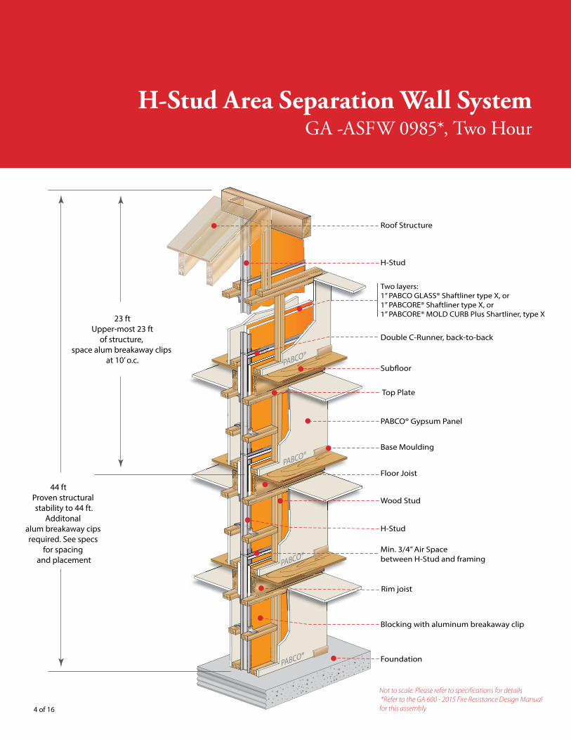
Roof Structure
Double C-Runner, back-to-back
Two layers:1” PABCO GLASS® Shaftliner type X, or1” PABCORE® Shaftliner type X, or 1” PABCORE® MOLD CURB Plus Shartliner, type X
Base Moulding
Rim joist
PABCO® Gypsum Panel
Sub�oor
Blocking with aluminum breakaway clip
Floor Joist
Top Plate
Wood Stud
Min. 3/4” Air Spacebetween H-Stud and framing
Foundation
H-Stud
H-Stud
PABCO®
PABCO®
PABCO®
PABCO®
44 ft Proven structural stability to 44 ft.
Additonalalum breakaway cipsrequired. See specs
for spacing and placement
23 ftUpper-most 23 ft
of structure, space alum breakaway clips
at 10’ o.c.
H-Stud Area Separation Wall SystemGA -ASFW 0985*, Two Hour
Not to scale. Please refer to specifications for details *Refer to the GA 600 - 2015 Fire Resistance Design Manual for this assembly
5 of 16
Introduction to The PABCO Area Separation Wall System (ASW)
The unique design of multifamily, multi-storied townhouses and condominiums requires special methods of construction that will provide fire resistance and acoustical separation between dwelling units The PABCO® H-Stud Area Separation Wall System (ASW) has been developed to meet these critical design criteria Weighing no more than ten pounds per square foot when erected, the PABCO H-Stud ASW provides a code compliant, efficient, lightweight and low cost solution for separating townhouses, condos and other multi-family dwelling units by eliminating the necessity of costly footers and foundation modifications An important benefit of the PABCO H-Stud ASW is that it may be easily erected directly onto a poured concrete slab by the contractor already on site Carpenters can easily install the H-Stud ASW modular system progressively once the framing for one residence is completed and prior to the construction of the adjacent unit The popularity of the non-load bearing gypsum board H-Stud ASW has grown as contractors and architects discover the efficiency, simplicity and cost effectiveness of the system
The PABCO H-Stud ASW is a two-hour fire resistance rated assembly specifically designed to protect the occupants in attached multi-unit residences Extending continuously from the foundation to, or through the roof, the PABCO H-Stud ASW provides sufficient structural stability under fire conditions to allow collapse of construction on either sided without the collapse of the wall The H-Stud ASW will also provide a sound attenuation of 60-64 STC where required and constructed to PABCO Gypsum’s specifications The PABCO H-Stud ASW can be constructed up to four stories (44 feet) tall, encompassing all common floor-ceiling heights, while providing the highest level of fire and sound performance
The key component of the PABCO H-Stud ASW is a continuous double layer of 1-inch thick, Type X, non-combustible PABCORE® Shaftliner, MOLD CURB® Plus Shaftliner or PABCO GLASS® Shaftliner panels installed in a continuous assembly from the foundation to the roof, and from the front to the back wall This construction restricts the spread of fire while maintaining sufficient structural stability under fire conditions to allow collapse of construction on either side without the collapse of the ASW or compromising structural integrity Structural support is provided by steel C-Runners and H-Studs Horizontal structural support is provided by L-Shaped “breakaway” aluminum slips, as described in the following section Depending upon the application, the ASW may be extended beyond the roof to form a parapet, or may terminate at the roof level
Shaftliner panels and metal components are easily stacked to allow progressive construction of the ASW during the framing stages of the building
BREAK AWAY ALUMINUM CLIPS allow for the collapse of the structure on the fire-exposed side without collapse of the entire wall or compromising its structural integrity The ASW assembly is attached to each unit’s structural framework using L-Shaped aluminum “breakaway” clips fastened to each side of the ASW’s steel H-Studs and to the structure of each unit The L-Shaped aluminum clips connect each H-Stud on both sides at the adjacent floors and roof/ceiling intersections to keep the area separation in place between the two structures The L-Shaped aluminum clips are designed to soften and yield to the heat of the fire at approximately 1,100°F When one side is exposed to fire, the clips on the exposed fire side soften and breakaway allowing the structure on the exposed fire side to collapse Because temperatures on the unexposed side of the ASW will be far below the point at which the clip will soften, the aluminum clips will remain intact allowing the ASW to remain intact and in place, thus protecting the adjacent townhouse
what the job demands
6 of 16
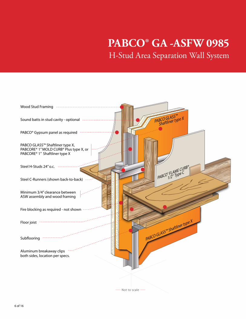
PABCO® GA -ASFW 0985H-Stud Area Separation Wall System
PABCO GLASS™ Shaftliner type X
PABCO® FLAME CURB®
1/2” Type C
PABCO GLASS™
Shaftliner type X
Not to scale
Wood Stud Framing
Sound batts in stud cavity - optional
PABCO® Gypsum panel as required
PABCO GLASS™ Shaftliner type X,PABCORE® 1” MOLD CURB® Plus type X, or PABCORE® 1” Shaftliner type X
Steel H-Studs 24” o.c.
Steel C-Runners (shown back-to-back)
Minimum 3/4” clearance betweenASW assembly and wood framing
Fire blocking as required - not shown
Floor joist
Sub�ooring
Aluminum breakaway clipsboth sides, location per specs.

7 of 16
Primary Assembly Components
PABCO® Gypsum Panels:The following products are suitable in this system:
• PABCO Glass® Shaftliner Type X 1”• PABCORE® MOLD CURB® Plus Shaftliner Type X 1”• PABCORE® Shaftliner Type X 1”• PABCO® Regular 1/2” • PABCO® LITECORE 1/2”• FLAME CURB® Type X 5/8”• FLAME CURB® Type XXX 1/2”• FLAME CURB® Type C 1/2”• MOLD CURB® Plus Type X 5/8”
width = 24”
thickness = 1”
Length = 8’, 9’ 10’ & 12’
PABCO GLASS® SHAFTLINER
PABCO GLASS® propriatary treated core providing �re resistant, mold-resistant and water-resistant
gypsum core, reinforced with glass �bers to increase its resilience.
Coated �berlass masts on both front and back panelsurfaces provide exceptional strength, resisting warping, rippling, buckling and sagging.
Double Beveled Edge for ease of installation
Steal H-Studs: H-studs are the key framing component, adding structural integrity to Area Separation Wall (ASW) assemblies. The H-studs secures two layers of 1” thick Saftliner panels between adjacent studs. The 2” wide H-Studs are inserted into the horizontal C-Runners .
2”
1-½”
Steal C-RunnersA C-runner is used at the top and bottom of vertical panels to secure 1” thick PABCO Shaftliner panels and H-studs in ASW assemblies. C-Runner is used back-to-back at intermediate floors to provide a joining system so that the ASW assembly can be erected one floor at a time. 2-1/8” galvanized steel. C-Runner, cap, edge or end closures 25 ga. (0.019”).
2”
1”
Aluminum Breakaway Clips: Aluminum Breakaway Clips are used as an integral part of the ASW assembly as a fuse attachment to the main wall assembly. This clip is designed to melt or yield to the high temperatures on the fire side of the wall allowing the fire engaged wall assembly to collapse while detaching to itself from the area separation wall. Breakaway clips on the non-fire side remain intact while holding the ASW in place as a barrier to contain the fire within the unit of origin.
2”
2”
2-½”

8 of 16
Primary Assembly Components H-Stud & C-Runner Properties
1” x 24“ PABCO GLASS® SHAFTLINER Type X , or1” x 24“ PABCORE® MOLD CURB® Plus SHAFTLINER Type X, or1” x 24“ PABCORE® SHAFTLINER Type X
2” C-Runner used as END CAP
2” C-Runner
2” C-Runner
2” H-Stud
AluminumBreakaway Clips(not shown)
H-STUD & C-RUNNER PROPERTIES:
Component Thickness Size
WeightGauge Design Thickness Width Length
H-Stud
25 ga (18 mil) 0.0188” (0.478 mm)
2-1/16” (52.4 mm)
8’ (2438 mm)
10’ (3048 mm)
12’ (3658 mm)
0.44 lbs/ft (0.656 kg/m)
C-Runner 2-1/8” (54 mm)8’ (2438 mm)
10’ (3048 mm) 0.27 lbs/ft
(0.400 kg/m)

9 of 16
Primary Assembly Components Fasteners & insulation
FASTENERS:Pan Head Screw 1/2”
• Attaching L-shaped Aluminum breakaway clip to H-Stud• Attaching horizontal C-Runner track to vertical C-Runner perimeter
tracks• Attaching back-back C-Runner tracks
Type W Drywall Screw 1-1/4”• Attaching L-Shaped Aluminum breakaway clip to wood framing
Drywall Nail 1-5/8”• Attaching 1/2” panel to wood studs and bearing plates of the
adjacent wall*
Steel Nail 16d• Assembly of adjacent wood framing
ACOUSTIC: • Acoustical insulation for wall cavity as specified
MISCELLANEOUS:• Mineral wool batt fire barrier is used where the ASW membrane
meets external walls and roofs
* For other products, Consult GA-216 or contact PABCO Technical Services

10 of 16
Technical Data & Features
TECHNICAL DATA:• The PABCO H-Stud ASW is a non-load bearing partition• The PABCO H-stud ASW is specifically designed to be used as a
2-hour wall separating units in multifamily construction• The PABCO H-stud ASW is not intended to be used as a shear wall• The PABCO H-stud ASW may be used in buildings up to four (4)
stories with a total height not to exceed 44 feet. • Penetrations or openings are not permitted in the PABCO H-stud
ASW• The PABCO H-stud ASW is designed to be laterally supported with
aluminum clips spaced at specified intervals as defined in the “Design Requirements” section
• Do not install insulation in the wall system until the building has been properly closed or dried-in to protect it from the weather
• PABCO GLASS® Sheathing should be used for all exposed faces of stud framing of Area Separation Walls which protrude beyond the roof or side walls
FEATURES: • Is easy to install with only three (3) basic components designed for
fast, easy installation that can be erected by carpenter tradesmen.• Can be constructed with or without a parapet, depending on local
code requirements • Provides continuous fire resistant membrane from foundation to
roof, unbroken by floor or structural members • Provides superior sound attenuation• Can be constructed in multifamily projects up to 44 feet in height• Weighs less than ten pounds per square foot (10p/ft2), resulting
in a considerable weight reduction when compared to concrete block
CODE COMPLIANCE:• For Party Walls, the PABCO H-Stud ASW must be continuous from
the foundation to the underside of the roof sheathing• For 2 hour fire walls, the PABCO H-Stud ASW must be continuous
from the foundation through the roof to form a parapet. The PABCO H-Stud ASW must allow for the collapse of the construction on the fire side of the wall while remaining intact to protect the structure on its opposite side.
11 of 16
Assembly Performance Testing
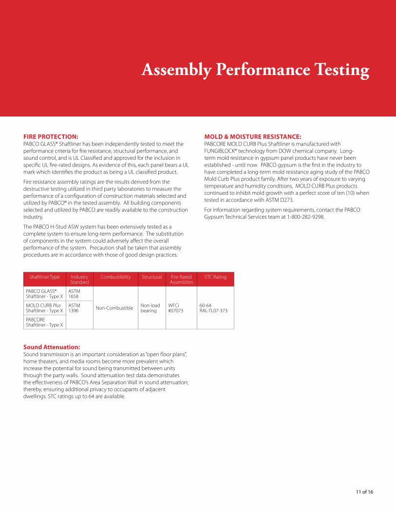
FIRE PROTECTION:PABCO GLASS® Shaftliner has been independently tested to meet the performance criteria for fire resistance, structural performance, and sound control, and is UL Classified and approved for the inclusion in specific UL fire-rated designs. As evidence of this, each panel bears a UL mark which identifies the product as being a UL classified product.
Fire resistance assembly ratings are the results derived from the destructive testing utilized in third party laboratories to measure the performance of a configuration of construction materials selected and utilized by PABCO® in the tested assembly. All building components selected and utilized by PABCO are readily available to the construction industry.
The PABCO H-Stud ASW system has been extensively tested as a complete system to ensure long-term performance. The substitution of components in the system could adversely affect the overall performance of the system. Precaution shall be taken that assembly procedures are in accordance with those of good design practices.
Shaftliner Type Industry Standard
Combustibility Structural Fire Rated Assemblies
STC Rating
PABCO GLASS® Shaftliner - Type X
ASTM 1658
Non-Combustible Non-load bearing
WFCi #07073
60-64 RAL-TL07-373
MOLD CURB Plus Shaftliner - Type X
ASTM 1396
PABCORE Shaftliner - Type X
Sound Attenuation: Sound transmission is an important consideration as “open floor plans”, home theaters, and media rooms become more prevalent which increase the potential for sound being transmitted between units through the party walls. Sound attenuation test data demonstrates the effectiveness of PABCO’s Area Separation Wall in sound attenuation; thereby, ensuring additional privacy to occupants of adjacent dwellings. STC ratings up to 64 are available.
MOLD & MOISTURE RESISTANCE:PABCORE MOLD CURB Plus Shaftliner is manufactured with FUNGIBLOCK® technology from DOW chemical company. Long-term mold resistance in gypsum panel products have never been established - until now. PABCO gypsum is the first in the industry to have completed a long-term mold resistance aging study of the PABCO Mold Curb Plus product family. After two years of exposure to varying temperature and humidity conditions, MOLD CURB Plus products continued to inhibit mold growth with a perfect score of ten (10) when tested in accordance with ASTM D273.
For information regarding system requirements, contact the PABCO Gypsum Technical Services team at 1-800-282-9298.

12 of 16
Design Requirements
SYSTEM, REQUIREMENTS:• When the total height of the ASW exceeds twenty-three feet
(23’) but nor more than forty-four feet (44’), the vertical spacing between rows of aluminum clips shall not exceed five feet (5’) o.c. for the lower twenty-three feet (23’), and ten feet (10’) o.c. for the portion above twenty-three feet (23’).
• When the ASW system is used as an exterior with adjacent framing on only one side, two (2) 1/2” Type S pan head screws are required for the clip attachment.
• Caulk all gaps between back-to-back C-Tracks with an approved fire caulking material.
• There shall be no penetrations in the PABCO GLASS® Shaftliner membrane.
ALUMINUM BREAK-AWAY” CLIP REQUIREMENTS: • Only use aluminum L-shaped clips to attach the PABCO H-stud
ASW to the adjacent framing members. In the event of a fire, the break-away clip is designed to melt, allowing the fire-side framing members to fall away leaving the two layers of 1” PABCO shaftliner intact.
• L-shaped aluminum clips are attached to each side of every H-stud (2 per stud) with two (2) 1/2” Type S pan head screws through the short leg of the clip. Secure the long leg of the clip to wood framing with one (1) 1-1/4” Type W screw.
• When the total height of the ASW exceeds twenty-three feet (23’) but not more than forty-four feet (44’), the vertical spacing between rows of aluminum clips shall not exceed five feet (5’) for the lower twenty-three feet (23’ ), and ten feet (10’) for the portion above twenty-three feet (23’).
• In the event that the H-stud does not align with the adjacent wood framing, insert blocking between wood framing members and attach aluminum clip to the blocking.
ACOUSTIC SEALING REQUIREMENTS:• Use an approved acoustical sealant and seal all penetrations, the
entire perimeter of wall/floor junctions, and the horizontal back-to-back C-runners with a minimum 1/4” bead of acoustical sealant.
• Membrane vertical T junction perimeters should be sealed for flanking noise using mineral wool insulation between vertical capping track and the external wall
• To maintain acoustic specifications, service penetrations through wood substrate framing should not be in contact with the ASW membrane, studs, tracks or clips.
• All penetrations in wood substrate should be sealed by applying an acoustical sealant.

13 of 16
Design Details
Roof Sheathing
PABCO® Gypsumbrand wallboard
Roof joist/rafter
2x4 top plate & wall framing
Roof truss member
Alum breakaway clips Gypsum board or mineral wool �re blocking as required
C-Runner
H-Stud Area Separation Wall Assemblywith two layers of 1” PABCORE® Shaftliner or MOLD CURB® Plus Shaftliner
TYPICAL ROOF INTERSECTION DETAIL
SJones 12-09
Elevation View
PABCO® Gypsumbrand wallboard
Floor joist
Sub�oor
2x4 top plate &wall framing
Alum breakaway clipsDouble C-Runnerback-to-back (horizontal)
Optional soundinsulation
H-Stud Area Separation Wall Assemblywith two layers of 1” PABCO shaftliner(see below for listing of products)
TYPICAL INTERMEDIATE FLOOR DETAILElevation View
Gypsum board or mineralwool �re blocking as required
PABCO® Gypsumbrand wallboard
Floor joist
Sealant as speci�ed
Foundation sill
Min 3/4” air space
C-Runner, fastened to foundation
Optional soundinsulation
TYPICAL FOUNDATION DETAILElevation View
Sub�oor
H-Stud Area Separation Wall Assemblywith two layers of 1” PABCO shaftliner(see below for listing of products)
Parapet height -(As required by local code) Roof Sheathing
Roof/Ceiling Joist
Roof Membrane
PABCO® Gypsumbrand wallboard 2x4 top plate & wall framing
Optional Sound Insulation
Alum breakaway clips Gypsum board or mineral wool �re blocking as required
C-Runner
Parapet Cap Flashing
TYPICAL ROOF INTERSECTION PARAPET DETAILElevation View
H-Stud Area Separation Wall Assembly with two layers of 1” PABCO shaftliner
PABCO® Gypsumbrand wallboard
Min 3/4” air space H-Stud
C-Runner
Optional sound insulation
Exterior Sheathing
Exterior Cladding
2x4 Wood Framing
EXTERIOR WALL INTERSECTION DETAILPlan View
H-Stud Area Separation Wall Assembly with two layers of 1” PABCO shaftliner
PABCO® Gypsum brand wallboard
Min 3/4” air space H-Stud
C- Runner
Flashing Cap
As RequiredOptional sound insulation
Exterior Gypsum Sheathing
Exterior Cladding
Exterior Wall Framing
PROTRUDING EXTERIOR WALL INTERSECTION DETAILPlan View
Gypsum board or mineral wool �re blocking as required
H-Stud Area Separation Wall Assembly with two layers of
1” PABCO shaftliner

14 of 16
Area Separation Wall Installation
INSTALLATION OF H-STUD AREA SEPARATION WALLSH-Stud Are Separation Walls (ASW) are installed either from above grade, top of masonry or concrete footings, which extend either to or through the roof deck; or from the foundation floor (slab) which extends either to or through the roof deck. The H-Stud ASW is progressively erected one floor at a time with each succeeding floor being stacked on top of the preceding floor.
FOUNDATIONIn typical construction, the PABCO® H-Stud ASW is installed from one end to the other one floor at a time. Succeeding floors are stacked on top of the lower completed floor. They are generally installed either (a) from the foundation (slab) to or through the roof deck or (b) from above grade top f masonry or concrete footings to or through the roof deck.
Step 1: Position the 2-1/8” C-Runner that will serve as the floor track allowing a 3/4” space for the wood stud framing on each side of the C-Runner and H-Studs. Apply acoustical sealant under each side of C-Runner along the edges to seal the juncture between the C-Runner track and the foundation or footing. Secure with power driven fasteners at both ends and spaced 24” o.c. down the length of the C-Runner. Space ends of adjacent C-Runner sections a minimum of 1/4” apart. Repeat the aforementioned fastening schedule.
Note: As an alternative to the 3/4” air space, the steel components (H-Studs and C-Runners) are permitted to be covered with one 6” wide gypsum batten attached to the framing on both sides with 1” Type S screws spaced 12” o.c. and screwed into alternate legs of H-Studs. 3” wide battens are installed over the C-Runners at the foundation and roof. Gypsum battens are cut from sheets of 1/2” PABCO® FLAME CURB® Super C Gypsum Board. The L-Shaped aluminum “breakaway” clips may then be attached directly to the steel studs through the gypsum board batten face into the H-Studs.
Step 2: Install a vertical 2-1/8” C-Runner track to the wall where the ASW intersects with a foundation wall of an exterior wall. Apply QuietSeal® Pro or equivalent under each side of C-Runner along the edges to seal the juncture between the C-Runner track and foundation wall and secure with power driven fasteners at both ends and spaced 24” o.c. down the length of the C-Runner. H-Studs, vertical C-Runner track, and PABCO GLASS® Shaftliner, PABCORE® MOLD CURB® Plus Shaftliner or PABCORE® Shaftliner panels (PABCO® Shaftliner Panels) are installed to the height of not more than 24” above the floor line of the floor above.
Step 3: Commence erecting the H-Stud ASW from either end at the foundation wall or exterior wall and the ASW intersection by inserting the first layer of 1” PABCO® Shaftliner Panel seating it into the C-Runner
foundation floor track and into the C-Runner foundation wall track. Once completed, insert the second PABCO® Shaftliner Panel back-to-back to the first panel, seating it into the C-Runner foundation floor track and into the C-Runner foundation wall track. PABCO® Shaftliner Panels and H-Studs may be set into position from either the basement floor or be fed down from the adjacent floor through the space provided in the wood framing.
Step 4: Ensure both of the PABCO® Shaftliner Panels are completely seated into the floor and vertical C-Runner tracks with their edges flush and in contact with the stud web. Insert and H-Stud flange over the long edges of the PABCO® Shaftliner Panels. Friction fit the H-Stud fully so that the PABCO® Shaftliner Panels’ long edges are flush and contact the stud web. Attach each flange of the vertical C-Runner track to the floor track with one 1/2” Type S pan head screw.
Step 5: Continue installing PABCO® Shaftliner Panels and H-Studs alternately in the manner described, ensuring that all H-Studs and PABCO® Shaftliner Panels are tightly nestled together until the first floor of the wall is completed within 24” of the end point of the wall. The last two PABCO® Shaftliner Panels are inserted from the adjacent floor above into the channel formed by the final H-Stud’s flange and the flanges of the C-Runner foundation wall track. Install a vertical 2-1/8” C-Runner track to the foundation walls where the ASW intersects. . Apply acoustical sealant under each side of C-Runner along the edges to seal the juncture between the C-Runner track and foundation wall and secure with power driven fasteners at both ends and spaced 24” o.c. down the length of the C-Runner. Before fastening the vertical C-Runner track flanges to the C-Runner floor track, cut the final two PABCO® Shaftliner Panels to the necessary width and insert these last two panels of 1” PABCO® Shaftliner Panels into the channel formed by the final H-Stud’s flange and the flanges of the C-Runner foundation wall track from the floor above. Once completed, ensure all H-Studs, C-Runner tracks and PABCO® Shaftliner Panels are tightly nested. Attach the H-Studs to the floor track on alternating sides with 1/2” Type S pan head screws.
Step 6: Cap the top edge of the erected foundation wall with 2-1/8” C-Runner track (legs down) installed horizontally over the top of the H-Studs and PABCO® Shaftliner Panels fastening the C-Runner track flanges at all corners on both sides with two 1/2” Type S pan head screws. Attach the H-Stud and vertical C-Runners to the adjacent wood framing by fastening L-Shaped aluminum “breakaway” clips to the ASW with one 1/2” Type S pan head screw through the short leg of the L-Shaped aluminum “breakaway” clip on each side of the ASW. Ensure a minimum of 3/4” air space is maintained between the H-Stud assembly and any adjacent framing members, and then fasten the long edge of the L-Shaped aluminum “breakaway” clip to the adjacent wood framing with one 8d nail of 1-1/4” Type W screw at the recommended point of attachment of the L-Shaped clip.

15 of 16
ASW Installation
INTERMEDIATE FLOORS AND ROOFStep 1: Installation to the intermediate H-Stud ASW continues by attaching a 2” C-Runner back to back (legs up) to the previously installed cap of the lower floor’s wall. This back-to-back C-Runner track installation creates the progressive erecting of the H-Stud ASW. Stagger the back-to-back C-Runner joints at least 12”, and fasten with Type S pan head screw at both ends and 24” o.c.Note: Always use back-to-back C-Runner track between floors in gypsum ASW. Substitution of a single H-Stud for the specified back-to-back C-Runner track is not allowed.
Step 2: Continue erecting-Studs and PABCO® Shaftliner Panels for succeeding floors in the same manner as described for the foundation wall with the exception that procedures for starting and ending point for the H-Stud ASW may vary depending on the exterior wall intersection detail and roof intersections.Step 3: When the H-Stud ASW has the adjacent wood framing on only one side and the exterior exposure on the other side, the L-shaped aluminum “breakaway” clips are attached to the H-Stud and the C-Runner with two ½” Type S pan head screws. Use one 1-1/4” Type W screw to attach to the adjacent exterior framing. Install code approved fire blocking between the solid wall system and adjacent framing at the floor lines, bottom of truss line, and any other locations required by the applicable code.
Fire blocking shall be installed at intermediate floors and roof locations. Either mineral wool or gypsum board filler may be utilized in the application.
Step 4: At top of floor, the H-Stud ASW may either extend to the top of the parapet wall or terminate at the underside of the roof deck.
Step 5: At the H-Stud ASW intersection with the roof, cut the H-Studs and PABCO® Shaftliner Panels to the required length and pitch to follow the roof-line. Cap the top edge of the wall with 2-1-8” C-Runner track installed horizontally over H-Studs and PABCO® Shaftliner Panels fastening the C-Runner track flanges at all corners on both sides with two ½” Type S pan head screws. Attach the H-Stud and vertical C-Runners to the adjacent wood framing by fastening L-Shaped aluminum “breakaway” clips. The L-Shaped aluminum “breakaway” clip are attached to adjacent framing on both sides and require attachment to the H-Stud and C-Runner with one ½” Type S pan head screw through the short leg of the clip. Ensure a minimum of ¾” air space is maintained between the H-Stud assembly and any adjacent framing members.
Note: When the total height of the ASW exceeds 23 feet but not more than 44 feet, the vertical spacing between the rows of the L-Shaped aluminum “breakaway” clips shall not exceed 10 feet. When the total height of the ASW exceeds 23 feet but not more than 44 feet, the vertical spacing between the rows of the L-Shaped aluminum “breakaway” clips shall not exceed 5 feet for the lower 23 feet and 10 feet for the portion above 23 feet.

what the job demands


