139
DOCUMENTATION

www.arkaos.net
D O C U M E N T A T I O N

The information in this document is subject to change without notice and does not represent a commitment on the part of ArKaos PRO S.A. No part of this publication may be copied, reproduced or otherwise transmitted or recorded, for any purpose, without prior written permission by ArKaos PRO S.A. All product and company names are ™ or © trademarks of their respective owners. © ArKaos PRO S.A. 2017. All rights reserved.

Table of Contents
ArKaos PRO Software License ............................................................ 9 GNU Lesser General Public License ................................................. 13 Introduction ......................................................................................... 16
Welcome to MediaMaster Version 5! .................................................... 16 Documentation ............................................................................................. 16 Express vs Pro ............................................................................................. 16
Installing the software - PC ................................................................... 17 Installing the software - Mac ................................................................. 17
About your license .............................................................................. 18 Activating your software........................................................................ 18
Software Activation Dialog ........................................................................... 18 About the Demo Mode ................................................................................. 18 Use Activation Code ..................................................................................... 19 Activate License Dongle ............................................................................... 19 Use Serial Key File ....................................................................................... 21
Introduction to the software ............................................................... 22 Control Concepts ................................................................................... 22
Theater Mode interface ................................................................................ 22 Fixture Mode interface.................................................................................. 22
Features Summary: ................................................................................ 23 Outputs ........................................................................................................ 23 Visual Presets – Theater Mode interface ...................................................... 23 Media Management (Express and Pro) ........................................................ 23 Layers – Theater Mode ................................................................................ 24
Software Interface Overview .............................................................. 25 Theater Mode interface .......................................................................... 25
Key features ................................................................................................. 25 Fixture Mode interface – MediaMaster Pro ........................................... 26
Key features ................................................................................................. 26 Full Screen Output ................................................................................. 26
Connecting an External Controller .................................................... 27 Setting up DMX Control ......................................................................... 27
Using ArtNet................................................................................................. 27 MSEX implementation (Pro edition only) ...................................................... 27 Support for grandMA MA-Net (Windows Only) ............................................. 27 Using an Enttec DMX USB Pro device ......................................................... 28
Setting up an Enttec DMX USB Pro device on a PC ...................................................28 Setting up an Enttec DMX USB Pro device on a Mac OSX .........................................29
Setting up MIDI Control.......................................................................... 29 Using the Software – Theater Mode................................................... 30
The main window ................................................................................... 30 Layer Previews ............................................................................................ 30 Layer Preview Customization ....................................................................... 31
Master Output ............................................................................................... 32 Master output controls .................................................................................................. 32 Masks (Instant mode only) ........................................................................................... 32 Keystoning (Instant mode only) .................................................................................... 33 Soft Edging (Instant mode only) ................................................................................... 33
Status indicators ........................................................................................... 33 Visual Preset and Preset Patch .................................................................... 34
Patch Selection............................................................................................................. 35 Latch Toggle ................................................................................................................. 35 Managing Patch and Visual presets (Copy, Paste, Edit,..) .......................................... 35
Show Settings......................................................................................... 36 DMX channels .............................................................................................. 36
Trigger Channels: ......................................................................................................... 36 Parameter Channels: ................................................................................................... 36 Patch Selector Channel:............................................................................................... 36 Patch Display offset Channel: ...................................................................................... 36 Brightness Channel ...................................................................................................... 36 Contrast Channel ......................................................................................................... 36 Master volume channel ................................................................................................ 36
MIDI controllers and notes ............................................................................ 37 Trigger Controllers: ....................................................................................................... 37 Trigger Notes: ............................................................................................................... 37 Parameter Controllers: ................................................................................................. 37 Patch Selector Controllers: .......................................................................................... 37 Patch Display offset Controllers: .................................................................................. 37 Brightness Controller: ................................................................................................... 37 Contrast Controller: ...................................................................................................... 37 Master volume Controller: ............................................................................................ 37
Keyboard shortcuts ....................................................................................... 38 Toggle Latch: ................................................................................................................ 38
Edit parameters for visual presets ........................................................ 38 Visual / Playback .......................................................................................... 39
Loop Mode .................................................................................................................... 39 Speed/Timecode: ......................................................................................................... 39 Loop In / Loop Out / Start Point .................................................................................... 39
Effect Configuration ...................................................................................... 39 Triggers: ....................................................................................................... 40
KEY............................................................................................................................... 40 DMX .............................................................................................................................. 40 MIDI .............................................................................................................................. 40
Position Parameters ..................................................................................... 40 Presets ......................................................................................................................... 40 Shapes ......................................................................................................................... 40 Auto Rotate ................................................................................................................... 41
Mixing Parameters ........................................................................................ 41 Max. Transparency ....................................................................................................... 41 Color Levels (Red/Green/Blue): ................................................................................... 42 Hue ............................................................................................................................... 42 Saturation ..................................................................................................................... 42 Lightness ...................................................................................................................... 42 Copy Mode ................................................................................................................... 42 Mask Mode – Chroma / Luminance Key ...................................................................... 43 Mask Centre ................................................................................................................. 43

Mask Size .....................................................................................................................43 Fade Time .....................................................................................................................43 Tiling .............................................................................................................................43
The Cue Player ....................................................................................... 44 Overview ...................................................................................................... 44 Getting started ............................................................................................. 44 The Cue Player interface .............................................................................. 45
The Toolbar ..................................................................................................................45 The Cue List .................................................................................................................45 Cue Selection ...............................................................................................................45 Adding a Cue ................................................................................................................45 Cue List Playback .........................................................................................................46 Properties Panel ...........................................................................................................46
Cue Properties ............................................................................................. 46 Main Tab .......................................................................................................................46
Cue List Properties ....................................................................................... 47 Cue List Tab .................................................................................................................47
Synchronization Modes ................................................................................ 47 Priority Layers .............................................................................................. 47 Halt cues ...................................................................................................... 47 Demo cue list ............................................................................................... 48 Advanced Topics.......................................................................................... 48
Reference Cue..............................................................................................................48 Freerun Cue ..................................................................................................................48 Mixing of Multiple Cues ................................................................................................48
Cue Player DMX, MIDI and Keyboard Controls ............................................ 49 DMX Chart Extension ...................................................................................................49 MIDI Chart Extension ...................................................................................................50 Keyboard Shortcuts ......................................................................................................50
Using the software – Fixture Mode .................................................... 51 The main window ................................................................................... 51
Previews area .............................................................................................. 51 Master output area ....................................................................................... 51 Status Indicators .......................................................................................... 51 Layer parameter area ................................................................................... 52
Visuals ..........................................................................................................................52 Effects ...........................................................................................................................52 Playback .......................................................................................................................53 Composition Modes ......................................................................................................54 Mapping ........................................................................................................................55 Position .........................................................................................................................55 Output ...........................................................................................................................55 Color .............................................................................................................................55 Cropping .......................................................................................................................56 Sound ...........................................................................................................................56
Media Types ......................................................................................... 57 Video ....................................................................................................... 57
Alpha source support ................................................................................... 57 Images ..................................................................................................... 57 Audio ....................................................................................................... 57

Generators .............................................................................................. 58 Effects ..................................................................................................... 58 Cameras / External Sources .................................................................. 58
Libraries ............................................................................................... 59 Library Management .............................................................................. 59
Overview and Library Concept ...................................................................... 59 Root Folder................................................................................................... 59 Media Folders and Naming Conventions ...................................................... 59
Building your libraries ........................................................................... 61 Adding visuals to the library .......................................................................... 62 Removing visuals from the library ................................................................. 62 Moving visuals in the library .......................................................................... 62 Renaming folders ......................................................................................... 62 File system ................................................................................................... 62 Changing the root folder ............................................................................... 63
Text Library ............................................................................................. 64 Lyrics Player ........................................................................................... 64 Timecode offsets .................................................................................... 65
Preferences Dialog ............................................................................. 66 Application Tab ...................................................................................... 66
Mode (MediaMaster Pro only) ....................................................................... 66 Server Name ................................................................................................ 66 Activate fullscreen at startup ......................................................................... 66 Start maximized ............................................................................................ 66 Autostart cue list ........................................................................................... 66
Output Tab .............................................................................................. 66 Instant mode ................................................................................................. 67 Full screen Display ....................................................................................... 67 Resolution .................................................................................................... 67 Multi-Display arrangement (Windows only) ................................................... 67 Soft Edge Span ............................................................................................ 68 Geometric correction & Soft-Edge per output (MediaMaster Pro) .................. 68
Geometric correction .................................................................................................... 68 Soft Edge per Output .................................................................................................... 70 Test grid and pattern .................................................................................................... 70
Video Mapper mode (MediaMaster Pro) ....................................................... 71 Hide mouse cursor in fullscreen (Mac only) .................................................. 71 Kling-Net ...................................................................................................... 71 LED Mapper ................................................................................................. 71 Engine Accuracy........................................................................................... 71 Timing Reference ......................................................................................... 72
DMX Tab .................................................................................................. 73 DMX Interface .............................................................................................. 73 Patch (Fixture mode only) ............................................................................. 74 Auto-Patch (Fixture mode only) .................................................................... 74
MIDI Tab (Theater mode only) ............................................................... 74 Audio Tab ................................................................................................ 75
Driver Type .................................................................................................. 75 Input Device ................................................................................................. 75 Output Device .............................................................................................. 75 Buffer Size ................................................................................................... 75 Hardware setup (Windows only) ................................................................... 75
Performances Tab .................................................................................. 76 Preview quality ............................................................................................. 76 Preview style ................................................................................................ 76 Flash Frame Rate Factor ............................................................................. 76
Activation Tab ........................................................................................ 77 Application Menus .............................................................................. 78
File ........................................................................................................... 78 Edit .......................................................................................................... 78 Display .................................................................................................... 78 Help ......................................................................................................... 79
Wide-screen & Multi-screen presentation ......................................... 80 Introduction ............................................................................................ 80 Definitions ............................................................................................... 80
Wide screen ................................................................................................. 80 Multi-screen ................................................................................................. 81
Case studies ........................................................................................... 81 Case 1: Dual head graphic card ................................................................... 81 Case 2: Dual head graphic card + single head graphic card ......................... 82 Case 3: Dual head graphic card + additional hardware ................................ 82 Other possible combinations ........................................................................ 82
Wide-screen or multi-screen projection – Setup ................................. 82 Monitors setup under Windows .................................................................... 82 Monitors setup under Mac OS X .................................................................. 84
Soft-Edge ............................................................................................. 85 Introduction ............................................................................................ 85 Soft-Edge in Instant Mode ..................................................................... 86 Calibration .............................................................................................. 87 Soft-Edge in VideoMapper Mode........................................................... 87 Calibration .............................................................................................. 88
VideoMapper ........................................................................................ 89 Concept ................................................................................................... 89 Hardware setup ...................................................................................... 89 Mapping workflow overview .................................................................. 89 VideoMapper application ....................................................................... 90
Interface overview ........................................................................................ 90 Toolbar ..........................................................................................................................90 Mapping Setup..............................................................................................................90 Sources .........................................................................................................................90 Surface Editor ...............................................................................................................90 Inspectors .....................................................................................................................90
Toolbar options ............................................................................................ 91
Setting up displays ....................................................................................... 91 Display corrections ....................................................................................... 93 Setting up surfaces ....................................................................................... 94
Masks ........................................................................................................................... 96 Cropping ....................................................................................................................... 96 Visual Sources.............................................................................................................. 97 Export and Import of Mapping Files ............................................................................. 97 Key Bindings................................................................................................................. 98
Output management in MediaMaster Pro ............................................. 99 Groups .......................................................................................................................... 99 DMX (Fixture mode only) ............................................................................................. 99
MediaHub ........................................................................................... 100 Concept ................................................................................................. 100 Getting Started ..................................................................................... 100 User Interface ....................................................................................... 100
Toolbar ....................................................................................................... 101 Left and Right Server Panels ...................................................................... 101 Synchronization Buttons ............................................................................. 101 Preferences ................................................................................................ 101 Transfers .................................................................................................... 102 Installer ....................................................................................................... 102 Troubleshooting .......................................................................................... 102
Firewall ....................................................................................................................... 102 Software Compatibility Issues .................................................................................... 102
Pixel Mapping over Kling-Net .......................................................... 103 Concepts ............................................................................................... 103 Hardware setup .................................................................................... 104 Mapping workflow overview ................................................................ 104 Kling-Net Mapper application .............................................................. 106
Overview .................................................................................................... 106 Connected Nodes ....................................................................................... 106 Connected Devices .................................................................................... 107 Mapped Objects ......................................................................................... 107 The canvas ................................................................................................. 107 Dividing and Splitting .................................................................................. 108
Dividing ....................................................................................................................... 108 Splitting ....................................................................................................................... 108
Output Selection ......................................................................................... 109 Test Pattern ................................................................................................................ 109 Screen Grabber .......................................................................................................... 109 MediaMaster ............................................................................................................... 109
Templates .................................................................................................. 110 Preferences ................................................................................................ 111 Pixel Perfect Mappings ............................................................................... 111 How to Display LED mappings from MediaMaster ...................................... 111
While the Kling-Net Mapper is running. ..................................................................... 111 While Kling-Net Mapper is not running. ..................................................................... 112
Pixel Mapping over DMX .................................................................. 113 LED Mapper 3 introduction .................................................................. 113

Overview of the new features ..................................................................... 113 Concepts .................................................................................................... 114 The integration of the LED Mapper with MediaMaster ................................ 114 Hardware setup and the Fixture Nodes list ................................................. 114
LED Mapper 3 interface........................................................................ 115 The main LED Mapper interface ................................................................. 115 The Fixture Library ..................................................................................... 116 Creating or modifying a LED Fixture ........................................................... 117 The Mapped Fixtures List ........................................................................... 117 Creating the LED mapping ......................................................................... 118 Selecting the network interface and the sender application ........................ 118 Editing the Device and DMX properties ...................................................... 119 Unicast versus Broadcast ........................................................................... 120 Editing the Mapping Properties .................................................................. 121 Deleting a device from the mapping ........................................................... 122 Mapped Devices Contextual Menu ............................................................. 122 Mapping resolution and pixel perfect sampling ........................................... 123 Project files ................................................................................................ 123
Performance tips ............................................................................... 124 Monitor Rate Versus Movie Rate ................................................................ 124 Hardware dependencies ............................................................................ 124 OS dependencies....................................................................................... 124
Windows OS ...............................................................................................................124 Mac OSX ....................................................................................................................124
Movie Compression ................................................................................... 125 Fixtures DMX Chart – Pro Version ................................................... 126
Layer Mini 1.0 ....................................................................................... 126 Layer Tiny 1.0 ....................................................................................... 127 Layer Full 1.1 ........................................................................................ 127 Layer Full 1.0 ........................................................................................ 130 Layer Extended .................................................................................... 130 Master Small 1.0 ................................................................................... 134 Master Full 1.0 ...................................................................................... 134 Master Full 1.1 ...................................................................................... 134
Terminology / Glossary of Terms .................................................... 135 Support, Information and Contact ................................................... 137
Solutions ............................................................................................... 137 ArKaos PRO Users Forum ......................................................................... 137 Knowledgebase articles ............................................................................. 137 Trouble Ticket System................................................................................ 137
Distributors and resellers .................................................................... 137
9
ArKaos PRO Software License
WARNING: DO NOT INSTALL THIS SOFTWARE UNTIL YOU HAVE READ AND ACCEPTED ALL THE TERMS OF THIS LICENSE. YOUR INSTALLATION OF THIS SOFTWARE WILL BE DEEMED TO BE YOUR ACCEPTANCE OF THE FOLLOWING TERMS AND YOUR WISH TO BECOME THE LICENSEE OF THIS ARKAOS PRO SOFTWARE, WHICH ACCEPTANCE SHALL BIND YOU AND ALL OF YOUR EMPLOYEES, AGENTS OR OTHER PARTIES WHO WILL USE THIS SOFTWARE TO THE TERMS OF THE SAID LICENSE. The ArKaos PRO Corporation (S.A. ARKAOS PRO, Chaussée de Waterloo, 198 B-1640 Rhode-Saint-Genèse - Belgium) is authorized to license the software of this installation (the ArKaos PRO MediaMaster Software) and by installing the licensee accepts a non-exclusive, non-transferable License to "Use" (as hereinafter defined) the ArKaos PRO MediaMaster Software (“Software”) on a single computer system ("The System"), subject to the terms and conditions contained herein. This License entitles the Licensee to: (a) make one working installation of the Software contained in this package on the System; (b) use the Software strictly in accordance with the provisions of Clause 2 of this License; (c) receive the benefit of the warranty specified herein; 1. Acceptance of this License. The terms and conditions of this License are deemed to be accepted by the parties as follows: (a) by the Licensor upon dispatch/delivery by the Licensor of this package to the Licensee, and (b) by the Licensee by installing the software. 2. Use of the Software. For the purposes of this License "Use" shall mean and include: a. Utilizing the whole or any part of the Software on one machine at a time. Utilizing means loading, transferring, copying or transmitting the Software into or within the single computer system for the processing of the system instructions or statements contained in the Software. b. Merging the whole or any part of the Software in machine-readable form into another software program. c. Copying the whole of the Software, which is in machine-readable form, into a machine readable copy for Use by the Licensee solely on the System and for the purpose only of understanding the contents of such readable material and for back up, PROVIDED THAT no more than one (1) copy will be in existence under any License at any one time without prior written consent from the Licensor. d. Storing the whole or any part of the Software on the System or other storage unit or disk. e. Utilizing (but not copying) the instructional and/or operational manuals relating to the Software. f. ACTIVATION CODE: With your purchase of the Software you will receive a unique Activation Code. This Activation Code will allow to unlock the protection in the Software so that it can run on a unique machine. Deactivating the software from one machine will allow to activate again the software on another machine. Once an Activation Code is used on one machine, this license doesn't give you right to activate and use the software on another machine. Activating and using multiple machines requires multiple Activation Codes. g. BACKUP LICENSE: A Backup License can be purchased by the Licensee for each owned license and will grant an extra Activation Code to activate and run the software on a second computer system. The Backup License only entitles the same Licensee to use the Software on the second computer system.

3. Licensee's Undertakings: The Licensee undertakes: a. Not to copy (other than for normal System operation and as specified in Clause 2 above), reproduce, translate (including electronic transfer), adapt, vary or modify the Software nor to communicate the same to any third party without the Licensor's prior written consent. b. To supervise and control Use of the Software in accordance with the terms of this License. c. To ensure that its employees, agents and other parties who will use the Software are notified of this License and the terms contained therein, and this prior to the said employee, agent or party using the said Software. d. To reproduce and include the copyright notice of the Licensor on all and any copies, whether in whole or in part, in any form, including partial copies of modifications of the Software made herein. e. Not to provide or otherwise make available the Software in whole or in part (including where applicable, but not limited to, program listings, object code and source program listings, object code and source code), in any form to any person other than the Licensee's employees or as specified in (c) above without prior written consent from the Licensor. f. To refrain from amending the method of working of the Software by way of reverse engineering, (necessary information to achieve the interoperability of the Software being available for the Licensee from the Licensor). 4. Warranty. a. The Licensee acknowledges that software in general is not error-free and agrees that the existence of such errors shall not constitute a breach of this License. b. In the event that the Licensee discovers a material error which substantially affects the Licensee's use of the same and notifies the Licensor of the error within 90 days from the date of dispatch of this License and the accompanying Software to the Licensee (the "warranty period"), the Licensor shall at its sole discretion either refund the license fee or use all reasonable endeavors to correct by patch or new release, also at its sole discretion, that part of the Software which does not so comply, PROVIDED THAT such non-compliance has not been caused by any modification, variation or addition to the original Software not performed by the Licensor or caused by its incorrect use, abuse or corruption or by use of the Software with other software or on equipment with which it is incompatible. 5. Source - Escrow. The Licensor has established certain source code deposit arrangements ("accord de séquestre") covering the source code and documentation for the "ArKaos PRO software" with the AGENCY FOR THE PROTECTION OF PROGRAMS (The A.P.P), W.T.C 10, route de l'Aéroport CH 125 Geneva. While this Agreement continues to exist, the Licensee will be entitled to receive the protection of such escrow arrangements in accordance with the rules and provisions of the "Procedure for the Applications of the Article 6 of the APP - IDDN - General Regulation ".

11
6. The Licensor's Liability. a. The Licensor shall not be liable to the Licensee for any loss or damage whatsoever or howsoever caused arising directly or indirectly in connection with this License, the Software, its use (whether or not as defined in this License) or otherwise, except to the extent that such liability may not be lawfully excluded. b. Notwithstanding the generality of (a) above, the Licensor expressly excludes liability for indirect, special, incidental or consequential loss or damage which may arise in respect of the Software, its Use, (whether or not as defined in this License), the System or in respect of other equipment or property, or for loss of profit, business, revenue, goodwill or anticipated savings. 7. Patents, Trademarks, Copyright and Intellectual Property Rights. a. The Licensee acknowledges that any and all of the trademarks, trade names, copyrights, patents and other intellectual property rights used or embodied in or in connection with the Software shall be and remain the sole property of the Licensor or such other party as may be identified therein or thereon. b. The Licensee shall not during or at any time after the expiry or termination of this License in any way question or dispute the ownership by the Licensor or rightful owners of any such rights. c. The Software, all copies of the software and derivative works based upon the Software or any part thereof remain the property of the Licensor. d. The Licensee shall indemnify the Licensor fully against all liabilities, costs and expenses which the Licensor may incur as a result of work done in accordance with the Licensee's specifications involving infringement of any copyright patent or other proprietary right. 8. Confidential Information. All information, data, drawings, specifications, documentation, software listings, source or object code which the Licensor may have imparted and may from time to time impart to the Licensee, relating to the Software, is proprietary and confidential. The Licensee hereby agrees that it shall use the same solely in accordance with the provisions of this License and that it shall not at any time during or after expiry or termination of this License, disclose the same, whether directly or indirectly, to any third party without the Licensor's prior written consent. The Licensee further agrees that it shall not itself or through any subsidiary, agent or third party modify, vary, enhance, copy, sell, lease, license, sub-license or otherwise deal in the Software or any part or parts, variations, modifications, copies, releases, versions or enhancements thereof or have any software or other program written or developed for itself based on any confidential information supplied by the Licensor. 9. Force Majeure. The Licensor shall be under no liability to the Licensee in respect of anything which, apart from this provision, may constitute breach of this License arising by reason of force majeure, namely, circumstances beyond the control of the Licensor. 10. Assignment. The Licensee shall not assign or otherwise transfer all or any part of the Software or this License without the prior written consent of the Licensor. 11. Waiver. Failure or neglect by either party to enforce at any time the provisions hereof shall not be construed nor shall be deemed to be a waiver of that party's rights hereunder nor any way affect the validity of the whole or any part of this License nor prejudice that party's rights to take subsequent action. 12. Severability.

In the event that any of these terms, conditions or provisions should turn out to be invalid, unlawful or unenforceable to any extent, such term, condition or provision shall be withdrawn from the remaining terms, conditions and provisions, which shall continue to be valid to the fullest extent permitted by law. 13. Law. The parties hereby agree that this License concluded between them and constituted on these terms and conditions shall be interpreted in accordance with Belgian Law. 14. Notices with respect to licenses administrated by MPEGLA. MPEG-4 Video Decoders and/or Encoders Notice THIS PRODUCT IS LICENSED UNDER THE MPEG-4 VISUAL PATENT PORTFOLIO LICENSE FOR THE PERSONAL AND NON-COMMERCIAL USE OF A CONSUMER FOR (i) ENCODING VIDEO IN COMPLIANCE WITH THE MPEG-4 VISUAL STANDARD (ÒMPEG-4 VIDEOÓ) AND/OR (ii) DECODING MPEG-4 VIDEO THAT WAS ENCODED BY A CONSUMER ENGAGED IN A PERSONAL AND NON-COMMERCIAL ACTIVITY AND/OR WAS OBTAINED FROM A VIDEO PROVIDER LICENSED BY MPEG LA TO PROVIDE MPEG-4 VIDEO. NO LICENSE IS GRANTED OR SHALL BE IMPLIED FOR ANY OTHER USE. AD.DITIONAL INFORMATION INCLUDING THAT RELATING TO PROMOTIONAL, INTERNAL AND COMMERCIAL USES AND LICENSING MAY BE OBTAINED FROM MPEG LA, LLC. SEE HTTP://WWW.MPEGLA.COM. AVC Royalty Product Notice THIS PRODUCT IS LICENSED UNDER THE AVC PATENT PORTFOLIO LICENSE FOR THE PERSONAL AND NON-COMMERCIAL USE OF A CONSUMER TO (i) ENCODE VIDEO IN COMPLIANCE WITH THE AVC STANDARD (ÒAVC VIDEOÓ) AND/OR (ii) DECODE AVC VIDEO THAT WAS ENCODED BY A CONSUMER ENGAGED IN A PERSONAL AND NON-COMMERCIAL ACTIVITY AND/OR WAS OBTAINED FROM A VIDEO PROVIDER LICENSED BY MPEG LA TO PROVIDE AVC VIDEO. NO LICENSE IS GRANTED OR SHALL BE IMPLIED FOR ANY OTHER USE. ADDITIONAL INFORMATION MAY BE OBTAINED FROM MPEG LA, LLC. SEE HTTP://WWW.MPEGLA.COM. AVC Sales to Codec Licensee Notice THIS PRODUCT IS LICENSED UNDER THE AVC PATENT PORTFOLIO LICENSE. SUCH LICENSE EXTENDS TO THIS PRODUCT ONLY AND ONLY TO THE EXTENT OF OTHER NOTICES WHICH MAY BE INCLUDED HEREIN. THE LICENSE DOES EXTEND TO ANY OTHER PRODUCT REGARDLESS OF WHETHER SUCH PRODUCT IS INCLUDED WITH THIS LICENSED PRODUCT IN A SINGLE ARTICLE. ADDITIONAL INFORMATION MAY BE OBTAINED FROM MPEG LA, LLC. SEE HTTP://WWW.MPEGLA.COM. 15. Notice with respect to the avcodec-54, avformat-54, swresample-0, swscale-2 and avutil-52 libraries originating from the FFMPEG project. The avcodec-54, avformat-54, swresample-0, swscale-2 and avutil-52 libraries are from the FFMPEG project. FFMPEG is a large project that allows recording, conversion and streaming of audio and video data. This product uses them to decompress MPEG based files. The author and primary copyright holder is Fabrice Bellard <fabrice.bellard at free.fr>. More information can be found at http://ffmpeg.sourceforge.net. The FFMPEG project is distributed under the GNU Lesser General Public License mentioned below.
13
GNU Lesser General Public License
Version 3, 29 June 2007 Copyright (C) 2007 Free Software Foundation, Inc. <http://fsf.org/> Everyone is permitted to copy and distribute verbatim copies of this license document, but changing it is not allowed. This version of the GNU Lesser General Public License incorporates the terms and conditions of version 3 of the GNU General Public License, supplemented by the additional permissions listed below. 0. Additional Definitions. As used herein, "this License" refers to version 3 of the GNU Lesser General Public License, and the "GNU GPL" refers to version 3 of the GNU General Public License. "The Library" refers to a covered work governed by this License, other than an Application or a Combined Work as defined below. An "Application" is any work that makes use of an interface provided by the Library, but which is not otherwise based on the Library. Defining a subclass of a class defined by the Library is deemed a mode of using an interface provided by the Library. A "Combined Work" is a work produced by combining or linking an Application with the Library. The particular version of the Library with which the Combined Work was made is also called the "Linked Version". The "Minimal Corresponding Source" for a Combined Work means the Corresponding Source for the Combined Work, excluding any source code for portions of the Combined Work that, considered in isolation, are based on the Application, and not on the Linked Version. The "Corresponding Application Code" for a Combined Work means the object code and/or source code for the Application, including any data and utility programs needed for reproducing the Combined Work from the Application, but excluding the System Libraries of the Combined Work. 1. Exception to Section 3 of the GNU GPL. You may convey a covered work under sections 3 and 4 of this License without being bound by section 3 of the GNU GPL. 2. Conveying Modified Versions. If you modify a copy of the Library, and, in your modifications, a facility refers to a function or data to be supplied by an Application that uses the facility (other than as an argument passed when the facility is invoked), then you may convey a copy of the modified version:
a) under this License, provided that you make a good faith effort to ensure that, in the event an Application does not supply the function or data, the facility still operates, and performs whatever part of its purpose remains meaningful, or b) under the GNU GPL, with none of the additional permissions of this License applicable to that copy. 3. Object Code Incorporating Material from Library Header Files. The object code form of an Application may incorporate material from a header file that is part of the Library. You may convey such object code under terms of your choice, provided that, if the incorporated material is not limited to numerical parameters, data structure layouts and

accessors, or small macros, inline functions and templates (ten or fewer lines in length), you do both of the following: a) Give prominent notice with each copy of the object code that the Library is used in it and that the Library and its use are covered by this License. b) Accompany the object code with a copy of the GNU GPL and this license document. 4. Combined Works. You may convey a Combined Work under terms of your choice that, taken together, effectively do not restrict modification of the portions of the Library contained in the Combined Work and reverse engineering for debugging such modifications, if you also do each of the following: a) Give prominent notice with each copy of the Combined Work that the Library is used in it and that the Library and its use are covered by this License. b) Accompany the Combined Work with a copy of the GNU GPL and this license document. c) For a Combined Work that displays copyright notices during execution, include the copyright notice for the Library among these notices, as well as a reference directing the user to the copies of the GNU GPL and this license document. d) Do one of the following: 0) Convey the Minimal Corresponding Source under the terms of this License, and the Corresponding Application Code in a form suitable for, and under terms that permit, the user to recombine or relink the Application with a modified version of the Linked Version to produce a modified Combined Work, in the manner specified by section 6 of the GNU GPL for conveying Corresponding Source. 1) Use a suitable shared library mechanism for linking with the Library. A suitable mechanism is one that (a) uses at run time a copy of the Library already present on the user's computer system, and (b) will operate properly with a modified version of the Library that is interface-compatible with the Linked Version. e) Provide Installation Information, but only if you would otherwise be required to provide such information under section 6 of the GNU GPL, and only to the extent that such information is necessary to install and execute a modified version of the Combined Work produced by recombining or relinking the Application with a modified version of the Linked Version. (If you use option 4d0, the Installation Information must accompany the Minimal Corresponding Source and Corresponding Application Code. If you use option 4d1, you must provide the Installation Information in the manner specified by section 6 of the GNU GPL for conveying Corresponding Source.) 5. Combined Libraries. You may place library facilities that are a work based on the Library side by side in a single library together with other library facilities that are not Applications and are not covered by this License, and convey such a combined library under terms of your choice, if you do both of the following: a) Accompany the combined library with a copy of the same work based on the Library, uncombined with any other library facilities, conveyed under the terms of this License. b) Give prominent notice with the combined library that part of it is a work based on the Library, and explaining where to find the accompanying uncombined form of the same work.

15
6. Revised Versions of the GNU Lesser General Public License. The Free Software Foundation may publish revised and/or new versions of the GNU Lesser General Public License from time to time. Such new versions will be similar in spirit to the present version, but may differ in detail to address new problems or concerns. Each version is given a distinguishing version number. If the Library as you received it specifies that a certain numbered version of the GNU Lesser General Public License "or any later version" applies to it, you have the option of following the terms and conditions either of that published version or of any later version published by the Free Software Foundation. If the Library as you received it does not specify a version number of the GNU Lesser General Public License, you may choose any version of the GNU Lesser General Public License ever published by the Free Software Foundation. If the Library as you received it specifies that a proxy can decide whether future versions of the GNU Lesser General Public License shall apply, that proxy's public statement of acceptance of any version is permanent authorization for you to choose that version for the Library.
Introduction
Welcome to MediaMaster Version 5!
The ArKaos PRO MediaMaster software has been created to offer an intuitive solution for the control of video media, animations and live picture inputs. It is a media server software that offers playback and real-time manipulation of clips, images and live feeds as well as flash text animations and real-time visual effect generators. The MediaMaster environment runs on both Windows and Mac OS platforms and integrates with your system hardware to offer a professional performance solution customised to your needs.
Documentation
The present User Guide covers all the aspects of MediaMaster Express and Pro version 5.0, including their extensions (LED Mapper, Kling-Net Mapper, Video Mapper, MediaHub…). Any changes, or any addition in the next intermediate releases (5.1, 5.2 etc..) will be detailed in the Release Notes PDF document, which can be found in the software installation folder on your computer. The Release Notes document completes this User Guide.
Express vs Pro
MediaMaster has two distinct user interfaces both with the power of the ArKaos PRO engine: the Theater mode and the Fixture mode interface. The Theater mode allows easy hands-on control via DMX, MIDI or even a computer keyboard. The Fixture mode offers a comprehensive fixture style interface for direct control over DMX off all parameters and attributes. MediaMaster is available in two different editions: Express and Pro. The Express edition is limited to the Theater mode interface and 12 layers of video, while the Pro edition enables both Theater mode and Fixture mode interface, 36 layers of video and the Video Mapper extension. Soft-Edge and Pixel-mapping control over DMX & Art-Net are available in both version but MediaMaster Pro adds a Geometric Correction module including advanced Soft-Edge settings per output and the Video Mapper extension for easy mapping of video onto irregularly shaped surfaces and through multiple outputs. The Video Mapper also offers advanced Soft-Edge, Geometric Correction and Per-display Color Correction. We hope you will enjoy using the software as much as we have enjoyed creating it for you! Sincerely, The ArKaos PRO team
17
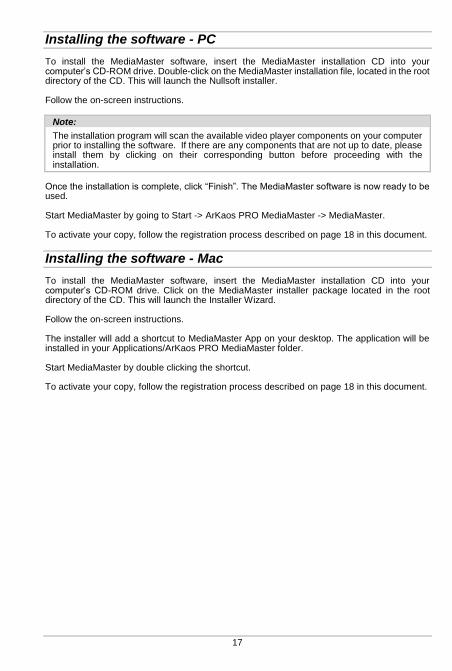
Installing the software - PC
To install the MediaMaster software, insert the MediaMaster installation CD into your computer’s CD-ROM drive. Double-click on the MediaMaster installation file, located in the root directory of the CD. This will launch the Nullsoft installer. Follow the on-screen instructions.
Note:
The installation program will scan the available video player components on your computer prior to installing the software. If there are any components that are not up to date, please install them by clicking on their corresponding button before proceeding with the installation.
Once the installation is complete, click “Finish”. The MediaMaster software is now ready to be used. Start MediaMaster by going to Start -> ArKaos PRO MediaMaster -> MediaMaster. To activate your copy, follow the registration process described on page 18 in this document.
Installing the software - Mac
To install the MediaMaster software, insert the MediaMaster installation CD into your computer’s CD-ROM drive. Click on the MediaMaster installer package located in the root directory of the CD. This will launch the Installer Wizard. Follow the on-screen instructions. The installer will add a shortcut to MediaMaster App on your desktop. The application will be installed in your Applications/ArKaos PRO MediaMaster folder. Start MediaMaster by double clicking the shortcut. To activate your copy, follow the registration process described on page 18 in this document.

About your license
Your software box comes with an Activation Code inside. It is very important that you keep this code in a safe place since it is the proof that you own a license and it might be needed in the future to re-install the software or to obtain upgrades. The Activation Code, however, is not the final serial number that will activate the software on your computer. To be able to run the software without limitations, you will need to create a serial number by following the instructions here after.
Note:
MediaMaster comes in two distinct editions: Express and Pro, please refer to “Express vs Pro” on page 16 for more info.
Activating your software
Software Activation Dialog
When you launch the application for the first time, it will display a “Software Activation” dialog.
About the Demo Mode
Note that, from the “Software Activation” dialog you can also choose to run the software in demo mode. If you do so, the software will still be fully functional but a ‘demo’ banner will be displayed randomly above the output. There are three possible demo modes related to the different MediaMaster editions: Express and Pro, please refer to “Express vs Pro” on page 16 for more info.
Note:
If you are not sure of your hardware setup and / or computer performance and you wish to make tests to decide whether you will use MediaMaster on a computer or not, we recommend to do so in demo mode since the software is fully functional in this mode. The demo mode also allows you to understand the differences between the Pro and the Express edition by letting you test the Theater mode interface or the Fixture interface.

19
Use Activation Code
To use this activation option you need a working Internet connection, a valid mail address and the activation code.
Fill in the activation code and your mail address and click “Next”. You will get a confirmation screen when the system is activated. You will also receive a confirmation mail and if you are using the activation code for the first time, you will also receive a password for your online customer account.
Activate License Dongle
To use this activation option you need a working Internet connection, a valid mail address, the activation code and a License Dongle.
If no License Dongle is detected or multiple License Dongles are detected you will not be able to click “Next”.
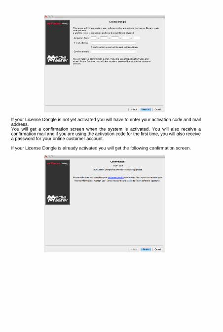
If your License Dongle is not yet activated you will have to enter your activation code and mail address. You will get a confirmation screen when the system is activated. You will also receive a confirmation mail and if you are using the activation code for the first time, you will also receive a password for your online customer account. If your License Dongle is already activated you will get the following confirmation screen.

21
Use Serial Key File
To use this activation option you need a serial key file (.aks) from www.arkaospro.com for this computer.
Introduction to the software
MediaMaster is a unique media server and visual effects software solution, which allows you to quickly create dynamic visual presentations. ArKaos PRO has long been established as a leading software developer for media control and the MediaMaster software has been designed to be as comprehensive in its functionality as possible and as such offers the perfect solution for the seamless real time integration of video into live performance, theatre, concerts and presentations.
Control Concepts
Theater Mode interface
The Theater mode interface of MediaMaster marks a new phase in software development allowing you to make use of the latest dynamic visual effects combined with an efficient and intuitive library management system and with Theater front end control via DMX, MIDI or even a computer keyboard. There are numerous attributes that must be defined to allow control of visuals in media servers – including content selection, playback speed, effects, size and position, keystoning etc. When these are directly controlled by a lighting console, such as with MediaMaster Pro’s Fixture interface, they can require a substantial number of control channels. MediaMaster’ Theater Mode interface allows you to make these decisions in the software itself and then simply take control of these visual presets using a few channels on your lighting desk or notes on a MIDI controller. Controlling the playback in the Theater Mode interface is much the same as using a dimmer to control a conventional fixture: think of rigging a profile light for a show – you decide first where to hang it, what color it should be, if you need a gobo or other effect’s device such as a scroller or animation disc. Once the fixture is rigged, prepared and focused you then only need to change the level of its dimmer as and when you require it in the show. Using the Theater Mode is the same – on the software you create the visual combination you want – define the content, any effects, playback speed etc. and then with your external controller simply fade it in an out as required during your show. Just like with a lighting system you can have multiple instruments – or in this case layers - to build your final show from. As such the Theater Mode gives you the same flexibility and control over your media as with a fixture based control solution but with an unprecedented ease of use.
Fixture Mode interface
MediaMaster Pro adds a fixture-based operation mode and as such acts as a traditional Media Server for professional lighting consoles such as ChamSys, Avolites, LSC, ETC, GrandMA, Martin, Compulite, etc. The fixture profiles allow total control of every MediaMaster parameter straight from the DMX console. To be able to send DMX commands to the server, you will need to set it up so it can communicate with your console. MediaMaster supports two different type of DMX connectivity: either using ArtNet or using a DMX USB widget.

23
Features Summary:
Outputs
MediaMaster is designed to work best with a minimum of a dual output computer system where the main screen shows the user interface and an output preview and the second screen (or screens) show the full resolution output image – this would normally be connected to a projector, screen, video mixer or LED display device. In MediaMaster, there are three types of output: Display outputs: “Displays” are the devices that are connected to the computer graphical
card(s) using DVI, HDMI, DisplayPort or VGA connectors. In Instant mode, there’s a single output called “Full screen Display” that correspond to the
full screen display (or multiple displays) that’s selected directly in the preferences. In Video Mapper mode, there are as many outputs as surfaces that are defined using the
“Video Mapper“ application. LED Mapper output: a set of LED devices controlled by the DMX protocol. The output
mapping is defined using the “LED Mapper” application. Kling-Net output: a set of LED devices controlled by ArKaos PRO Kling-Net protocol. The
output mapping is defined using the “Kling-Net Mapper” application. You can switch between Instant and Video Mapper Display modes, and activate LED Mapper and Kling-Net outputs in the Output tab of the Preferences window. MediaMaster can assign visuals to layers, and each layer can be assigned to a single output or a group of outputs that are defined within the application. You can create groups using the dedicated “Output” dialog that’s accessible in the “Outputs Management” menu item (CTRL + O / Cmd + O). There are numerous ways to configure your outputs, which are discussed later in this manual.
Visual Presets – Theater Mode interface
In the Theater Mode interface the choice of playback visuals is organized into patches and you can create up to 124 patches with up to 128 visual presets in each patch – that’s 15872 possible visual presets for each media library.
Media Management (Express and Pro)
As its name suggests MediaMaster can handle numerous different types of media sources – including video, flash, quartz compositions, images, external cameras and sources and even audio when attached to a video file. These media files are organized into library folders in exactly the same way that you would create and manage files on the computer. There are 256 library folders and each folder can have up to 255 individual pieces of media (one media file is always kept as a blank slot by the software). Some of the library folders in ArKaos PRO are pre-defined for specific duties – such as camera feeds or text effects - and these will be covered in a later section of this manual. It is also possible to have more than one library and this is also covered later.

Note:
Think of the media management as a set of filing cabinets – you have a total of 256 drawers and each draw can store 256 files in it. By creating a good filing practice you can quickly and easily find the content you need.
For example you can group clips by type or project into a specific folder so folder 001 has cloud animations, folder 002 has computer game visuals, folder 003 has slides for a specific event and so on and so forth.
With a possible media library of over 60,000 clips it can be really helpful to organise clips in this manner and make the recall of clips even more efficient.
In the Theater Mode your set-up configuration and show information is automatically saved into the library folder as it is created so the next time you boot the software you will have the exact set-up you last created. No need to keep saving – ArKaos PRO stores it all for you alongside your media library. In the Fixture Mode your set-up configuration and preferences are saved with the software but as the show will be controlled driven via DMX your show settings would be stored on the lighting console or controller you use with the software.
Layers – Theater Mode
MediaMaster Express is capable of running 12 layers of media playback simultaneously and uses a LTP (last takes precedence) rule when more than 12 visual presets are selected. The LTP rule means that the software automatically moves visual presets when layers become empty so that any new cues always jump to the highest (top) layer available. For example if you activate visual presets 1 through 12 in sequence so that each one is running on a different layer simultaneously and then activate visual preset 13 the first visual preset you selected (which was allocated to layer 1) will be removed and all of the visual presets move up a layer – so the visual preset on layer 2 moves to layer 1 and so on. If you fade out one layer – for example the visual preset on layer 4 – then the layers automatically move up – so the visual preset on layer 5 moves to layer 4 and so on. It will work the same way when running MediaMaster Pro in Theater Mode except that you will have access to 36 layers. The resolution of the video content is limited only by what your computer hardware can handle so with the right hardware 36 layers of High Definition (or greater) video is more than possible.
25
Software Interface Overview
Theater Mode interface
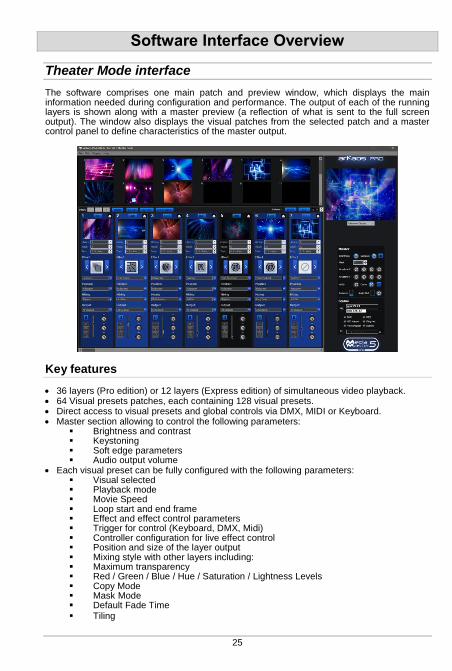
The software comprises one main patch and preview window, which displays the main information needed during configuration and performance. The output of each of the running layers is shown along with a master preview (a reflection of what is sent to the full screen output). The window also displays the visual patches from the selected patch and a master control panel to define characteristics of the master output.
Key features
36 layers (Pro edition) or 12 layers (Express edition) of simultaneous video playback. 64 Visual presets patches, each containing 128 visual presets. Direct access to visual presets and global controls via DMX, MIDI or Keyboard. Master section allowing to control the following parameters:
Brightness and contrast Keystoning Soft edge parameters Audio output volume
Each visual preset can be fully configured with the following parameters: Visual selected Playback mode Movie Speed Loop start and end frame Effect and effect control parameters Trigger for control (Keyboard, DMX, Midi) Controller configuration for live effect control Position and size of the layer output Mixing style with other layers including: Maximum transparency Red / Green / Blue / Hue / Saturation / Lightness Levels Copy Mode Mask Mode Default Fade Time Tiling

Fixture Mode interface – MediaMaster Pro
The Fixture Mode interface available in MediaMaster Pro is organized along one main window that displays most of the information needed during a performance. It shows the 36 individual layer outputs as well as the master preview (the reflection of what is sent to the full screen output) and a parameter panel allowing accessing and modifying the settings for each layer. Parameters can be either modified through the user interface or from the DMX console. If you modify a parameter on the user interface, it will keep its value unless a change happens in DMX values. It then re-syncs to the value sent by the console. In order to drive MediaMaster from a DMX console, you will need to select in your console a fixture that is compatible with the software. Within MediaMaster there are couple of different fixture types in order to allow control of the software from small to high-end consoles with a different set of parameter controls available with each fixture type. An extensive description of the fixture types is available later in this document in the “Fixtures DMX Chart – Pro Version” section 126.
Key features
The software provides for up to 36 layers of video. Each layer can run one visual and one effect, and gives DMX control over the following parameters: Visual selected (a visual is either a video, an image, a text, or an input from a camera or an
acquisition board…) Text (selectable text displayed in text animations) Layer transparency (dimmer) Effect and parameters Full cropping features (to transform your media server into a full-on, live video mixer) Position and size of the layer output Copy mode to blend with underlying layer Playback mode and Movie Speed Chrominance and Luminance Keying Movie start and end frame Tiling Mapping on 3D objects (plane, sphere, cylinder) 3D Object rotation Color control Output selection and edition Additionally, after all layers have been composed, there is a master section allowing to control the overall brightness and contrast, keystoning, soft-edge and volume parameters.
Full Screen Output
By default, when you start the software, the full screen output is not enabled. If you want to activate the full screen either by selecting the menu Display > Toggle Full screen or by pressing CTRL+F on Windows / Cmd+F on Mac. The full screen output can be launched automatically when the application is started by setting this as default in the preferences (see page 67 for further details) If you don’t have a dual output setup configured then the full screen will be activated on the main screen and the main interface will disappear. To exit the full screen mode, press CTRL+F / Cmd+F again. For more information on setting up a dual output system, see the “Preferences Dialog” on page 66 and the “Wide-screen & Multi-screen presentation” on page 80 in this document.

27
Connecting an External Controller
Setting up DMX Control
To be able to control MediaMaster via DMX, you’ll need to set it up so it can receive information from your console. MediaMaster supports two different types of DMX connectivity: either using ArtNet or using a DMX USB widget.
Using ArtNet
If your console supports ArtNet, you simply have to connect an Ethernet cable from the console to the computer running the MediaMaster software. On Mac computers the hardware is usually auto sensing so a standard network cable may be used. On Windows computers you may need a crossover cable if linking directly between the console and the computer running Media Master. MediaMaster presents itself as an ArtNet Node that receives all incoming DMX data on a selected range of DMX universes. For your computer to appear on the ArtNet network, you need to set its IP address within the range of the network – this is usually something like 2.X.X.X with an IP mask of 255.0.0.0 (this can be done in the control panel on Windows or System Preferences on MAC OS) If you decide to use MediaMaster using the ArtNet protocol, go in the Preferences Dialog and, in the DMX tab, select ‘ArtNet’ as DMX Interface and set the subnet and universes you want to be listening to.
Note:
Like any lighting fixture or dimmer MediaMaster will “listen” to all channels on the selected universe but only respond to the channels it is addressed to. It is quite feasible therefore to have other fixtures using different addresses on the same universe in much the same way as you could use a variety of moving lights, dimmers and LED’s all on the same universe.
For more information about ArtNet network configuration, check out the Artistic License web site at http://www.artisticlicence.com/.
MSEX implementation (Pro edition only)
MSEX stands for Media Server Extension and is a protocol that runs on top of DMX over Ethernet allowing for bi-directional communication between the media server and console. This allows for information on specific items to be passed from MediaMaster to the console. This includes media (images and video); effects; cues; crossfades; masks; blend presets; effects presets; and image presets. MediaMaster’s MSEX implementation is compatible with most of the lighting consoles, like ChamSys and Compulite. MediaMaster complies with the MSEX version 1.1 specifications, including thumbnails and live preview for visuals.
Support for grandMA MA-Net (Windows Only)
MediaMaster can be directly driven from grandMA consoles supporting the MA-eDMX protocol. To activate MA-Net, go to the DMX tab in the Preferences Dialog and select “MA-Net” from the DMX Interface drop down box:
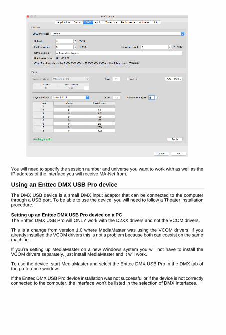
You will need to specify the session number and universe you want to work with as well as the IP address of the interface you will receive MA-Net from.
Using an Enttec DMX USB Pro device
The DMX USB device is a small DMX input adaptor that can be connected to the computer through a USB port. To be able to use the device, you will need to follow a Theater installation procedure.
Setting up an Enttec DMX USB Pro device on a PC
The Enttec DMX USB Pro will ONLY work with the D2XX drivers and not the VCOM drivers. This is a change from version 1.0 where MediaMaster was using the VCOM drivers. If you already installed the VCOM drivers this is not a problem because both can coexist on the same machine. If you’re setting up MediaMaster on a new Windows system you will not have to install the VCOM drivers separately, just install MediaMaster and it will work. To use the device, start MediaMaster and select the Enttec DMX USB Pro in the DMX tab of the preference window. If the Enttec DMX USB Pro device installation was not successful or if the device is not correctly connected to the computer, the interface won’t be listed in the selection of DMX Interfaces.
29
Setting up an Enttec DMX USB Pro device on a Mac OSX
The Enttec DMX USB Pro will ONLY work with the D2XX drivers and not the VCOM drivers. Under Mac OS X if the VCOM driver is installed it will prevent MediaMaster to work with the D2XX interface. To avoid this you can delete the VCOM driver by opening a terminal window and typing: sudo rm -rf /System/Library/Extensions/FTDIUSBSerialDriver.kext You can also open the /System/Library/Extensions folder and delete the file FTDIUSBSerialDriver.kext if present You will need to have Administrator privileges on the system to do this. You will also need to reboot the computer after you have deleted the file. If you’re setting up MediaMaster on a new Mac OS X system you will not have to install the VCOM drivers separately, just install MediaMaster and it will work. If the Enttec DMX USB Pro device installation was not successful or if the device is not properly connected to the computer, the interface won’t be listed in the selection of DMX Interfaces available in the Preferences dialog.
Setting up MIDI Control
To be able to control MediaMaster via MIDI, you will just need to have a MIDI device connected and properly installed on your system before starting the application. Then, from the MIDI input type tab from the Show Settings dialog (see page 36) you can check the device availability and define how the software will respond to the MIDI signals from your controller.
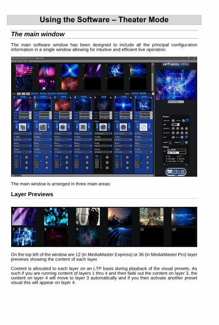
Using the Software – Theater Mode
The main window
The main software window has been designed to include all the principal configuration information in a single window allowing for intuitive and efficient live operation.
The main window is arranged in three main areas:
Layer Previews
On the top left of the window are 12 (in MediaMaster Express) or 36 (in MediaMaster Pro) layer previews showing the content of each layer. Content is allocated to each layer on an LTP basis during playback of the visual presets. As such if you are running content of layers 1 thru 4 and then fade out the content on layer 3, the content on layer 4 will move to layer 3 automatically and if you then activate another preset visual this will appear on layer 4.
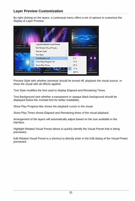
31
Layer Preview Customization
By right clicking on the layers, a contextual menu offers a set of options to customize the display of Layer Preview.
Preview Style tells whether previews should be turned off, playback the visual source, or show the visual with all effects applied. Text Style modifies the font used to display Elapsed and Remaining Times. Text Background sets whether a transparent or opaque black background should be displayed below the overlaid text for better readability. Show Play Progress Bar shows the playback cursor in the visual. Show Play Times shows Elapsed and Remaining times of the visual playback. Arrangement of the layers will automatically adjust based on the size available in the interface. Highlight Related Visual Preset allows to quickly identify the Visual Preset that is being previewed. Edit Related Visual Preset is a shortcut to directly enter in the Edit dialog of the Visual Preset previewed.

Master Output
To the right hand side of the software window is the master output section. At the top of this is a preview of the output to your external display coupled with an output selector. This preview shows the result of the composition of all the active layers on the selected output. This allows you to see what is being sent to your external device and also to prepare and preview your show without the need to connect an external output.
Master output controls
Under the output preview are the master parameter controls. Below is a quick description of each control you can see in the picture on the left, in the next pages we’ll describe how to use these settings in more detail. Master brightness and contrast These global settings can be controlled either by mouse control or by defining remote DMX or MIDI channels for Brightness and Contrast from the “SHOW” dialogue box which can be opened using the button at the top of the visuals patch window.
Blackout button If the blackout button is selected then the external output will go to BLACK – but the preview window will still show the layer composition preview. Mask selection (Instant mode only) Use it to recall a master mask from the library to overlay on the output.
Master Keystone Settings for X and Y (Instant mode only) These allow precise global keystone settings to be defined in order to digitally calibrate the output to ensure the best position of the visuals onto the screen or display unit.
Width and Curve settings for Soft-Edging (Instant mode only)
When using a multi screen output these controls allow you to configure the blending zone between the two projectors – the width sets the size of the overlapping strip and the curve defines how strong the soft edge blending should be to ensure you can calibrate the overlap to a seamless image with even brightness.
Master Volume
The “Volume” controls the volume of the output when your visuals contain some audio tracks. This way you can make sure that the audio plays in a proper way even when it has been recorded at different levels.
Note:
The aspect ratio of the layer preview is 4:3 ratio and therefore if you are working with an output of a different aspect ratio (for example 16:9 or a custom widescreen) the output will be shown “squashed to fit” within the preview window.
Masks (Instant mode only)
When a new media library is created the Masks folder is set as folder 255. Masks consists of

33
black and white or grayscale jpeg images. When a mask file is recalled from this folder using the Mask selection in the master control the white is automatically removed and the black left in tact to create a mask over the top of the output layers content.
Note:
In addition to providing some interesting and unique shapes the mask function is particularly useful when working with circular or irregular shaped screens. By recalling a mask shape you can quickly and easily ensure that all content is masked to fit the screen.
Keystoning (Instant mode only)
You can alter the master keystone settings for the output using the virtual encoders on the master section of the main software window.
The Keystone functions on Media Master allow you to digitally keystone BOTH the Vertical and Horizontal sides of the image. The power and control offered by MediaMaster gives you far greater range and precision than that offered in the built in settings of most projectors.
Keystoning allows you to digitally alter the image in order to help fit the output to the screen. For example if the projector is mounted slightly off axis to the screen then you may choose to adjust the keystoning to give the impression of a flat image. The keystone settings on MediaMaster allow you to modify the position of each of the four corners of the image within the output window by changing the X/Y coordinates of each corner.
Note:
Unlike using shutters on a profile light Keystoning does not cut or mask any of the image. Instead the action of Keystoning moves these corners but all pixels of output remain the same – they are just in different positions on the screen. MediaMaster automatically adjusts the pixel composition to fit within the new keystoned parameters.
Keystoning only shows on the output window as it is directly related to the output display you are using. It is a global setting across the full width of the output display so for example if you are using two projectors side by side to make a single wide image then the keystone function will manipulate the top right and bottom right of one projector and the top left and bottom left of the other.
Soft Edging (Instant mode only)
Soft edging is used when several projectors are combined to build one big scene. In such cases, you often have to overlap the images sent by every projector in order to blend them correctly. The two soft-edge parameters allow controlling the blending zone in between each projector: the width parameter sets the width of the overlapping strip while the curve defines how strong the soft-edge blending should be. For more information about setting up soft-edge, refer to the “Preference Dialog” section about Soft Edge Span on page 68 and to the “Soft-Edge” chapter on page 85.
Status indicators
These give a summary of the current operational statistics including the FPS (frames per second) of the graphics processing unit (GPU) and the central processing unit (CPU) of the computer. The two FPS bars give performance information about the engine. The first line (GPU) shows indication of the current frame rate. It is active only when in full
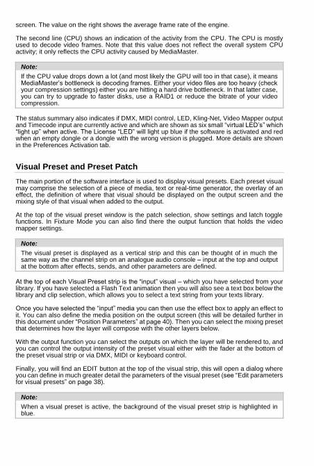
screen. The value on the right shows the average frame rate of the engine. The second line (CPU) shows an indication of the activity from the CPU. The CPU is mostly used to decode video frames. Note that this value does not reflect the overall system CPU activity; it only reflects the CPU activity caused by MediaMaster.
Note:
If the CPU value drops down a lot (and most likely the GPU will too in that case), it means MediaMaster’s bottleneck is decoding frames. Either your video files are too heavy (check your compression settings) either you are hitting a hard drive bottleneck. In that latter case, you can try to upgrade to faster disks, use a RAID1 or reduce the bitrate of your video compression.
The status summary also indicates if DMX, MIDI control, LED, Kling-Net, Video Mapper output and Timecode input are currently active and which are shown as six small “virtual LED’s” which “light up” when active. The License “LED” will light up blue if the software is activated and red when an empty dongle or a dongle with the wrong version is plugged. More details are shown in the Preferences Activation tab.
Visual Preset and Preset Patch
The main portion of the software interface is used to display visual presets. Each preset visual may comprise the selection of a piece of media, text or real-time generator, the overlay of an effect, the definition of where that visual should be displayed on the output screen and the mixing style of that visual when added to the output. At the top of the visual preset window is the patch selection, show settings and latch toggle functions. In Fixture Mode you can also find there the output function that holds the video mapper settings.
Note:
The visual preset is displayed as a vertical strip and this can be thought of in much the same way as the channel strip on an analogue audio console – input at the top and output at the bottom after effects, sends, and other parameters are defined.
At the top of each Visual Preset strip is the “input” visual – which you have selected from your library. If you have selected a Flash Text animation then you will also see a text box below the library and clip selection, which allows you to select a text string from your texts library. Once you have selected the “input” media you can then use the effect box to apply an effect to it. You can also define the media position on the output screen (this will be detailed further in this document under “Position Parameters” at page 40). Then you can select the mixing preset that determines how the layer will compose with the other layers below. With the output function you can select the outputs on which the layer will be rendered to, and you can control the output intensity of the preset visual either with the fader at the bottom of the preset visual strip or via DMX, MIDI or keyboard control. Finally, you will find an EDIT button at the top of the visual strip, this will open a dialog where you can define in much greater detail the parameters of the visual preset (see “Edit parameters for visual presets” on page 38).
Note:
When a visual preset is active, the background of the visual preset strip is highlighted in blue.
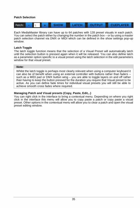
35
Patch Selection
Each MediaMaster library can have up to 64 patches with 128 preset visuals in each patch. You can select the patch either by changing the number in the patch box – or by using a master patch selection channel via DMX or MIDI which can be defined in the show settings pop-up window.
Latch Toggle
The latch toggle function means that the selection of a Visual Preset will automatically latch until the selection button is pressed again when it will be released. You can also define latch as a parameter option specific to a visual preset using the latch selection in the edit parameters window for that visual preset.
Note:
Whilst the latch toggle is perhaps most clearly relevant when using a computer keyboard it can also be of benefit when using an external controller with buttons rather than faders – such as a MIDI pad or DMX button wing – you are able to toggle layers on and off rather than having to keep the button pressed for the duration you require that Visual preset to be active. As you can define fade times for individual visual presets you will still be able to achieve smooth cross fades where required.
Managing Patch and Visual presets (Copy, Paste, Edit,..)
You can right click in the interface to bring a contextual menu. Depending on where you right click in the interface this menu will allow you to copy paste a patch or copy paste a visual preset. Other options in the contextual menu will allow you to clear a patch and open the visual preset editing window.
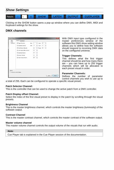
Show Settings
Clicking on the SHOW button opens a pop-up window where you can define DMX, MIDI and Keyboard settings for the show.
DMX channels
With DMX input type configured in the master preferences window of the software this DMX show setting window allows you to define how the software should respond to incoming DMX data on the configured universe.
Trigger Channels:
This defines what the first trigger channel should be and how many there are – you can have up to 255 trigger channels which will be allocated to each preset visual in order.
Parameter Channels:
Defines the number of parameter control channels you wish to use up to
a total of 255. Each can be configured to operate a specific visual preset.
Patch Selector Channel:
This is the controller that can be used to change the active patch from a DMX controller.
Patch Display offset Channel:
Select the index of the first visual preset to display in the patch by scrolling through the visual presets.
Brightness Channel
This is the master brightness channel, which controls the master brightness (luminosity) of the software output.
Contrast Channel
This is the master contrast channel, which controls the master contrast of the software output.
Master volume channel
This master volume channel controls the output volume of the visuals that run with audio.
Note:
Cue Player tab is explained in the Cue Player session of the documentation.
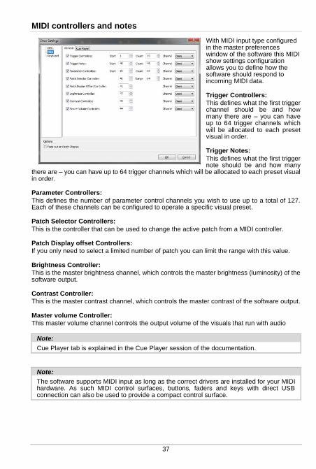
37
MIDI controllers and notes
With MIDI input type configured in the master preferences window of the software this MIDI show settings configuration allows you to define how the software should respond to incoming MIDI data.
Trigger Controllers:
This defines what the first trigger channel should be and how many there are – you can have up to 64 trigger channels which will be allocated to each preset visual in order.
Trigger Notes:
This defines what the first trigger note should be and how many
there are – you can have up to 64 trigger channels which will be allocated to each preset visual in order.
Parameter Controllers:
This defines the number of parameter control channels you wish to use up to a total of 127. Each of these channels can be configured to operate a specific visual preset.
Patch Selector Controllers:
This is the controller that can be used to change the active patch from a MIDI controller.
Patch Display offset Controllers:
If you only need to select a limited number of patch you can limit the range with this value.
Brightness Controller:
This is the master brightness channel, which controls the master brightness (luminosity) of the software output.
Contrast Controller:
This is the master contrast channel, which controls the master contrast of the software output.
Master volume Controller:
This master volume channel controls the output volume of the visuals that run with audio
Note:
Cue Player tab is explained in the Cue Player session of the documentation.
Note:
The software supports MIDI input as long as the correct drivers are installed for your MIDI hardware. As such MIDI control surfaces, buttons, faders and keys with direct USB connection can also be used to provide a compact control surface.

Keyboard shortcuts
“Learn” button can be used to detect the next key pressed and assign it as keyboard shortcut.
“ESC” key allows to cancel the learn operation. “DEL” or “Backspace” can be used to remove a keyboard shortcut.
Toggle Latch:
Key shortcut to toggle latch mode on and off.
Note:
Cue Player tab is explained in the Cue Player session of the documentation.
Edit parameters for visual presets
At the top of each visual preset strip is an EDIT button. Clicking on this opens a dialog allowing detailed configuration of each of the parameters for that particular visual preset.
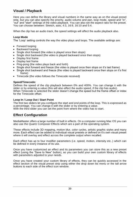
39
Visual / Playback
Here you can define the library and visual numbers in the same way as on the visual preset strip, but you can also specify the priority, audio volume and pan, loop mode, speed and “in”, “out” and “start” settings of the video playback. You can also set the aspect ratio for the preset. You can choose between: Stretch, auto, 4:3, 16:9, 16:10 and 5:4. When the clip has an audio track, the speed settings will affect the audio playback also.
Loop Mode
The ‘Loop’ setting controls the way the video plays and loops. The available settings are: Forward looping Backward looping Single shot forward (the video is played once then stops) Single shot backward (the video is played backward once then stops) Display first frame Display last frame Ping-pong (the video plays back and forth) Single shot forward and freeze (the video is played once then stops on it’s last frame) Single shot backward and freeze (the video is played backward once then stops on it’s first
frame) Timecode (the video follows the Timecode received)
Speed/Timecode:
Defines the speed of the clip playback between 0% and 400%. You can change it with the slider or by entering a value (this will also affect the audio speed, if the clip has audio). When Timecode is selected the slider doesn’t change the speed but the frame offset or index for the Timecode offset.
Loop In / Loop Out / Start Point
The first two sliders let you configure the start and end points of the loop. This is expressed as a percentage. You can change it with the slider or by entering a value. With the third slider you can set the point from where the video has to start.
Effect Configuration
MediaMaster offers a large number of built in effects. On a computer running Mac OS you can also use the Quartz Composer Effects which are a part of the operating system. These effects include 3D mapping, motion blur, color cycles, artistic graphic styles and many more. Each effect can be added to individual visual presets or defined on it’s own visual preset where it will overlay and effect across the complete output when recalled. Each effect has up to four modifier parameters (i.e. speed, motion, intensity etc..) which can be defined in every instance of its use. Once you have customized an effect and its parameters you can store this as a new preset effect (using the “Save to New” button), so you can build your own custom library of effects with parameters adjusted to your needs. Once you have created your custom library of effects, they can be quickly accessed in the effect section of the visual preset strip using either the drop down list menu or the tall arrow buttons to each side of the effect icon window.
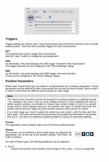
Triggers:
Trigger settings are used to start / stop visual presets and control their intensity in the currently selected patch. There are three possible triggers for each visual preset:
KEY
The keyboard key used to trigger this visual preset. Use the “Learn” button to change the key assignment.
DMX
As information, the panel displays the DMX trigger channel for this visual preset. The trigger channels can be configured in the “Show Settings” dialog.
MIDI
As information, the panel displays both MIDI trigger note and controller. Those can be configured in the “Show Settings” dialog.
Position Parameters
Within each Visual Preset you can define a comprehensive set of position parameters. These parameters can be defined for each visual preset but can also be saved (using “Save to New”) in order to recall them for different preset visuals at a later stage.
Note:
The “Save to New” function can also be thought of as storing a palette on a lighting console - for example if you have a set up using multiple screens or pixel mapping and want to define specific position co-ordinates to ensure that certain content is sent to a specific screen area or pixel mapped area you can position one piece of content and store this position preset and then apply the same position preset to other pieces of content.
If at a later stage you need to adjust the preset you can recall it, edit the data and then Save again. This will overwrite the previous preset and update this information in all presets that use it – the same as updating a position palette for a piece of automated lighting.
Presets
The application comes shipped with a set of common position presets.
Shapes
The position can be defined in three shape types by selecting the appropriate icon at the top of the position display: Flat Plane, 3D Cube or Sphere. For each of these types, the following attributes can be adjusted: Pos X
Defines the top-left corner position of the image on the X axis – so for an image 800
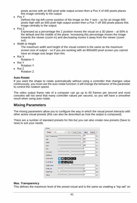
41
pixels across with an 800 pixel wide output screen then a Pos X of 400 pixels places this image centrally to the output.
Pos Y Defines the top-left corner position of the image on the Y axis – so for an image 600 pixels high with an 600 pixel high output screen then a Pos Y off 300 pixels places this image centrally to the output.
Pos Z Expressed as a percentage the Z position moves the visual on a 3D plane – at 50% is the default and the middle of the plane. Increasing this percentage moves the image towards the viewer (zoom in) and decreasing moves it away from the viewer (zoom out).
Width & Height The maximum width and height of the visual content is the same as the maximum screen size of output – so if you are working with an 800x600 pixel screen you cannot have an image size larger than this.
Rot X Rotation X
Rot Y Rotation Y
Rot Z Rotation Z
Auto Rotate
If you want the shape to rotate automatically without using a controller that changes value continuously, you must use the auto rotate function; it will change the behavior of the parameter to control the rotation speed. The video output frame rate of a computer can go up to 60 frames per second and most consoles will not send that many controller values per second, so you will have a smoother result when using auto rotate.
Mixing Parameters
The mixing parameters allow you to configure the way in which the visual preset interacts with other active visual presets (this can also be described as how the output is composed). There are a number of standard presets for this but you can also create new presets (Save to new) to suit your needs.
Max. Transparency
This defines the maximum level of the preset visual and is the same as creating a “top set” on

a lighting console. For example if you set the Max. Transparency to 80% then even if you fade the visual in to the top of its fader (full) you will still be able to see through it to the layer below.
Color Levels (Red/Green/Blue):
The three color sliders allow you to adjust the amount of each color to be represented in the image. With all sliders at full (100%) then it is possible to achieve a white output. Once you reduce any of these sliders then you limit the color tone of the image – this can be very useful in adjusting clips to suit a particular color scheme or mood. It can also be helpful when creating visuals for projection onto colored surfaces where adjusting the color balance can help to ensure the original image is best represented against a tinted background.
Hue
Much used for color correction, hue lets you slide a virtual color wheel before your output.
Saturation
This defines how saturated the output will be.
Lightness
Lightness is often confused with brightness because they both make the output brighter but the big difference is that where brightness adds light to everything (black becomes grey) Lightness only adds light to the light areas so black remains black.
Copy Mode
The copy mode defines the basic composition between the current layer and previous layers. MediaMaster supports the following options:
Replace: In this mode, the pixels of the Visual Preset are written on top of the previous
active layers. This is the default mode. Addition: In this mode, the pixel values of the current layer are added to the ones of the
previous layers. This means that “dark” pixels in the current layer image won’t alter the pixels that are underneath while “light” pixel will saturate the image underneath.
Subtraction: In this mode, the pixel values of the current layer are subtracted from the pixel
value in the underlying layers. Dark pixel from the current layer won’t alter the pixel of the layers underneath while light pixel will darken them.
Multiplication: In this mode, the pixels from the current layer will be multiplied by the pixels
of the underlying layers. For a pixel to appear bright in the output, the equivalent pixel of the current layer and the underlying layer needs to be bright. If any of the layers has a dark pixel, the result will be dark.
Minimum: This mode takes the pixel that is the darkest between the current layer and the
layer underneath. Maximum: This mode takes the pixel that is the brightest between the current layer and the
layer underneath.

43
Mask Mode – Chroma / Luminance Key
There are 5 basic mask modes for content. These affects how the content interacts with other running content.
Keying is a technique where some pixels are made transparent depending on their characteristics. Creating a Key is simply defining this interaction depending on the color or brightness of a pixel. Chrominance Keying (or Chromakey) – ‘removes’ pixels based on their colors – for example the “blue screen” technique. Luminance Keying – ‘removes’ pixels based on their brightness level. The masking mode switches allow you to select, from left to right: no keying luminance keying (band reject) luminance keying (band pass) chrominance keying (band reject) chrominance keying (band pass) Band reject means that the selected luminance/color band will disappear while band pass will let the selection through.
Mask Centre
The center of the mask defines mid point tolerance of the mixing mode – varying this amount will change the amount of pixels that can be seen based on the type of mask used.
Mask Size
This defines the range of the mask algorithm – generally speaking the higher the mask size the more pixels can be seen from the layers underneath.
Fade Time
This function allows you to predefine the fade time for the Visual Preset when activated. The default fade time is 0 milliseconds (ms). When a new fade time is set which can be anywhere between 0 and 10,000 milliseconds (0-10seconds) the fade down timing is also taken from this parameter setting. The fade time is set as a complete fade from 0 – 100%, if you choose to fade the layer from 0-50% it will take half of the preset fade time.
Tiling
The Tiling Function allows you to tile the output of that visual preset. At 0% the visual preset takes up the whole screen – as you increase the percentage the visual preset is tiled numerous times to fill the screen area with each tile presented at the same aspect ratio as the full screen output.
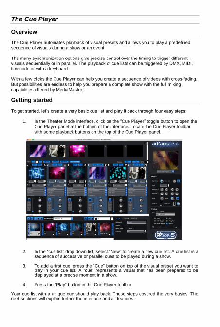
The Cue Player
Overview
The Cue Player automates playback of visual presets and allows you to play a predefined sequence of visuals during a show or an event. The many synchronization options give precise control over the timing to trigger different visuals sequentially or in parallel. The playback of cue lists can be triggered by DMX, MIDI, timecode or with a keyboard. With a few clicks the Cue Player can help you create a sequence of videos with cross-fading. But possibilities are endless to help you prepare a complete show with the full mixing capabilities offered by MediaMaster.
Getting started
To get started, let’s create a very basic cue list and play it back through four easy steps:
1. In the Theater Mode interface, click on the “Cue Player” toggle button to open the Cue Player panel at the bottom of the interface. Locate the Cue Player toolbar with some playback buttons on the top of the Cue Player panel.
2. In the “cue list” drop down list, select “New” to create a new cue list. A cue list is a sequence of successive or parallel cues to be played during a show.
3. To add a first cue, press the “Cue” button on top of the visual preset you want to
play in your cue list. A “cue” represents a visual that has been prepared to be displayed at a precise moment in a show.
4. Press the “Play” button in the Cue Player toolbar.
Your cue list with a unique cue should play back. These steps covered the very basics. The next sections will explain further the interface and all features.
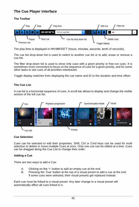
45
The Cue Player interface
The Toolbar
The play time is displayed in HH:MM’SS”T (hours, minutes, seconds, tenth of seconds). The cue list drop-down list is used to switch to another cue list or to add, erase or remove a cue list. The filter drop-down list is used to show only cues with a given priority or free-run cues. It is sometimes more convenient to focus on the sequence of cues for a given priority, and for some other tasks to see cues of all priorities interleaved. Toggle display switches from displaying the cue name and ID to the duration and time offset.
The Cue List
A cue list is a horizontal sequence of cues. A scroll bar allows to display and change the visible section of the full cue list.
Cue Selection
Cues can be selected to edit their properties. Shift, Ctrl or Cmd keys can be used for multi selection to delete or move multiple Cues at once. Only one cue can be edited at a time. Cues can be dragged along the Cue List to change their order.
Adding a Cue There are two ways to add a Cue:
A. Clicking on the ‘+’ button to add an empty cue at the end. B. Pressing the ‘Cue’ button at the top of a visual preset to add a cue at the end.
If some cues were selected, their visual presets get replaced instead. Each cue must be linked to a visual preset. Any later change to a visual preset will automatically affect all cues linked to it.
Cue info
Cue
Priority
Synchronization Mode Playback progression
Previous cue
Play
Pause
Stop
Next cue
Play time
Cue list drop down list
Add cue
Delete cues
Toggle display
Filter list
Visual
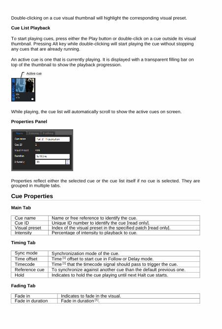
Double-clicking on a cue visual thumbnail will highlight the corresponding visual preset.
Cue List Playback
To start playing cues, press either the Play button or double-click on a cue outside its visual thumbnail. Pressing Alt key while double-clicking will start playing the cue without stopping any cues that are already running. An active cue is one that is currently playing. It is displayed with a transparent filling bar on top of the thumbnail to show the playback progression.
While playing, the cue list will automatically scroll to show the active cues on screen.
Properties Panel
Properties reflect either the selected cue or the cue list itself if no cue is selected. They are grouped in multiple tabs.
Cue Properties
Main Tab
Cue name Name or free reference to identify the cue. Cue ID Unique ID number to identify the cue [read only]. Visual preset Index of the visual preset in the specified patch [read only]. Intensity Percentage of intensity to playback to cue.
Timing Tab
Sync mode Synchronization mode of the cue.
Time offset Time [1] offset to start cue in Follow or Delay mode.
Timecode Time [1] that the timecode signal should pass to trigger the cue.
Reference cue To synchronize against another cue than the default previous one.
Hold Indicates to hold the cue playing until next Halt cue starts. Fading Tab
Fade in Indicates to fade in the visual. Fade in duration Fade in duration [1].
Active cue

47
Fade out Indicates to fade out the visual. Fade out duration Fade out duration [1].
Cue List Properties
Cue List Tab
Name Name of the cue list. Loop at end Restart the cue list when the end is reached. Timecode offset Applies an offset to all timecode defined in the cue list.
[1] Times, offsets or durations can be defined with any hour, minute, second or millisecond specification like in the following examples: “1h 23m 15s 900ms”, “1h 23s”, “50m 15ms”
Synchronization Modes
A cue has one of the following Synchronization mode:
Halt The operator needs to press explicitly the Play button or send a DMX or MIDI trigger to play the cue.
Follow Play the cue after a given time offset when the previous or reference cue ends.
Delay Play the cue after a given time offset when the previous or reference cue starts.
Timecode Play the cue when the timecode has passed the given time.
Crossfade Play Cues to follow each other with a small overlap to perform a crossfading.
The Synchronization mode can be changed either by right-clicking on a Cue or by editing the cue properties.
Priority Layers
Introduced by the visual presets, each cue is associated to a priority layer to determine if the visual should be played as background, normal or foreground. The priority filter dropdown list allows to focus on one priority layer at the time. Each cue is synchronized by default to the previous cue on the same priority layer. In other words background, normal and foreground cues run by default in parallel.
By using filters, it becomes easier to handle the sequence and the transitions of cues to be played for each priority layer successively. That means focusing on background sequence first, then adding normal priority content and finally adding visuals on foreground.
Halt cues
Halt cues interrupt the show until the user asks to continue. They interrupt cues and are visible on all priority layers. A Halt cue activates when all cues before and with any priority have finished. If a cue has the property Hold, then it will continue to play until the show continues again.

Cues of any priority placed after a Halt will only play once the Halt event has been passed. Also a cue can’t reference another cue if separated by a Halt. Only freerun Cues can reference any Cue.
Demo cue list
A demo cue list is deployed when a new library is created. If you use currently an existing library, you can still create a new library to see the demo cue list. In the Library Management dialog, click the button “Set Root folder…” and specify the location where the new Library should be deployed.
Advanced Topics
Reference Cue
By default the synchronization of a cue is done relative to the previous cue on the same priority layer. But each cue can also specify explicitly another cue to be used as the reference cue or “origin” to refer to the start of the cue list. By setting an explicit reference cue ID, for instance multiple cues can be synchronized to the same cue or cues can be synchronized between multiple priority layers.
A Cue will display a link icon to show that an explicit reference cue has been specified.
Freerun Cue
Freerun cues run independently of the main flow of the cue list, can reference any cue and are not interrupted by Halt cues. They can be triggered by timecode at any moment. Freerun cues allow the Cue Player to provide a convincing solution to trigger visual presets by timecode with fade-in and fade-out at the end. They also provide a good option to prepare visual patterns that can be triggered at any moment in a show. To create freerun cues, select a freerun filter in the filter drop-down list and add cues to it. Cues or freerun cues can’t reference a cue with a bigger ID (further on the right when displayed with “all” priority filter). An exception are freerun cues which can reference any non-freerun cue. Also cues can never reference a freerun cue.
Mixing of Multiple Cues
The Cue Player is used to automate the playback of different visual presets. But in the end, the rules of the Theater mode still apply to mix together the multiple active visual presets. All visual preset parameters (playback, looping, effect, positioning, priority, mixing and output) can be used to leverage the full mixing capability of MediaMaster through the Cue Player. Delay synchronization mode, priority layers and freerun cues give various solutions to play multiple cues simultaneously. In addition, other visual presets can still be driven by DMX, MIDI or mouse and keyboard and mixed together while the Cue Player is running.

49
Cue Player DMX, MIDI and Keyboard Controls
DMX Chart Extension
Chan. Name
Def. Chan.
Ranges Def. Val.
Loc. Val.
Snap/ Instant
Category
Cue List [1] 30 0-255 0 0 YES BEAM
Cue [1] 31 0-255 0 0 YES BEAM
Cue Player Control [2]
32 0-7 None 8-15 Play 16-23 Pause 24-31 Stop 32-39 Previous Cue 40-47 Next Cue 48-55 Toggle Play/Pause 56-63 Change Cue List 64-71 Jump to Cue
0 8 YES BEAM
Cue Player Play
33 0-127 Trigger off 128-255 Trigger on [3]
0 0 YES BEAM
Cue Player Pause
34 0-127 Trigger off 128-255 Trigger on [3]
0 0 YES BEAM
Cue Player Stop
35 0-127 Trigger off 128-255 Trigger on [3]
0 0 YES BEAM
Cue Player Previous Cue
36 0-127 Trigger off 128-255 Trigger on [3]
0 0 YES BEAM
Cue Player Next Cue
37 0-127 Trigger off 128-255 Trigger on [3]
0 0 YES BEAM
Cue Player Toggle Play/Pause
38 0-127 Trigger off 128-255 Trigger on [3]
0 0 YES BEAM
Cue Player Change Cue List [1]
39 0-127 Trigger off 128-255 Trigger on [3]
0 0 YES BEAM
Cue Player Jump to Cue [1]
40 0-127 Trigger off 128-255 Trigger on [3]
0 0 YES BEAM
[1] Cue and Cue List can be changed by first selecting their indices and then triggering either Change Cue List or Jump to Cue. [2] Actions triggers the first time a value in a new action range is received. [3] Action triggers when the DMX value changes from below 128 to above or equal 128.

MIDI Chart Extension
Controllers / Notes Def. ID Def. Channel
Cue List Controller 100 OMNI
Cue Controller 101 OMNI
Play Note 102 OMNI
Pause Note 103 OMNI
Stop Note 104 OMNI
Previous Cue Note 105 OMNI
Next Cue Note 106 OMNI
Toggle Play/Pause Note 107 OMNI
Keyboard Shortcuts
Action
Cue Player Play
Cue Player Pause
Cue Player Stop
Cue Player Previous Cue
Cue Player Next Cue
Cue Player Toggle Play/Pause
Note:
All keyboard, MIDI and DMX controls can be tweaked in the Show Settings dialog.
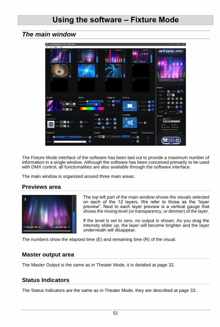
51
Using the software – Fixture Mode
The main window
The Fixture Mode interface of the software has been laid out to provide a maximum number of information in a single window. Although the software has been conceived primarily to be used with DMX control, all functionalities are also available through the software interface. The main window is organized around three main areas:
Previews area
The top left part of the main window shows the visuals selected on each of the 12 layers. We refer to those as the “layer preview”. Next to each layer preview is a vertical gauge that shows the mixing level (or transparency, or dimmer) of the layer. If the level is set to zero, no output is shown. As you drag the Intensity slider up, the layer will become brighter and the layer underneath will disappear.
The numbers show the elapsed time (E) and remaining time (R) of the visual.
Master output area
The Master Output is the same as in Theater Mode, it is detailed at page 32.
Status Indicators
The Status Indicators are the same as in Theater Mode, they are described at page 33.
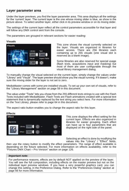
Layer parameter area
Under the layer previews, you find the layer parameter area. This area displays all the settings for the ‘current’ layer. The current layer is the one whose mixing slider is blue, as show in the picture above. To select another layer, either click in its preview window or on its mixing slider. The settings of the current layer reflect all the control parameters accessible for that layer and will follow any DMX control sent from the console. The parameters are grouped in relevant sections for easier reading:
Visuals
This zone shows the visual currently selected on the layer. Visuals are organized in libraries for easier access. There are 256 libraries each containing up to 255 visuals (one visual slot is reserved as a blank image). Some libraries are also reserved for special usage (flash texts, acquisitions input and masking) but most of them are user configurable through the visual library management dialog.
To manually change the visual selected on the current layer, simply change the values under “Library” and “Visual”. The layer preview should show you the visual running. If it doesn’t, make sure the mixing slider for the layer is not set to zero. MediaMaster comes with some pre-installed visuals. To set up your own set of visuals, refer to the “Library Management” section on page 59 in this document. The value under “Texts” lets you chose from the 255 different texts strings to use with the Flash Texts included with MediaMaster. Flash Texts are Flash animations created with a special text statement that is dynamically replaced by the text string you select here. For more information on the Text Library, please refer to page 64 in this document. The aspect ratio button enables you to change the aspect ratio for this layer.
Effects
This zone displays the effect setting for the current layer. Effects are also organized in libraries for easier grouping. Each effect can have up to four parameters that are displayed on the right side of the panel. Selecting an effect is done by modifying the values into the “Library” / “Effect” fields,
then use the rotary button to modify the effect parameters. The range of effect available is depending on the fixture selected. For more information on effects availability, refer to the “Fixtures DMX Chart – Pro Version” section on page 126.
Important note:
For performance reasons, effects are by default NOT applied on the preview of the layer. You will see the full composition, including effects on the master preview but not on the individual layer preview windows. If you have a very powerful graphics card, you can change this setting, in the Preference Dialog. Refer to the “Preferences Dialog” section at page 66 for more information.
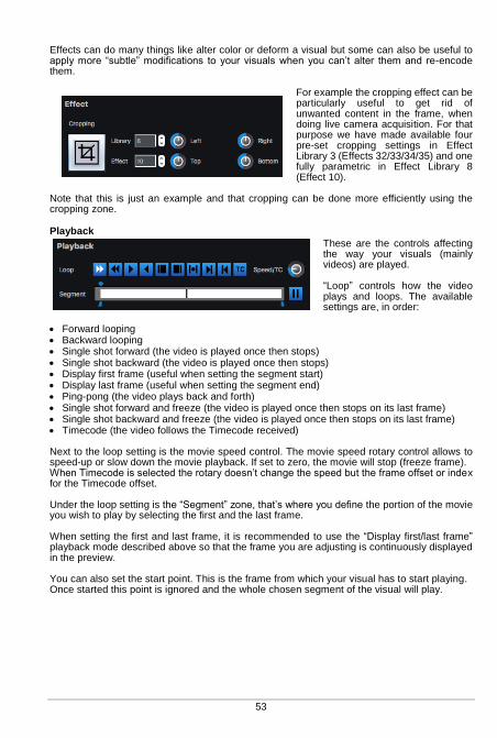
53
Effects can do many things like alter color or deform a visual but some can also be useful to apply more “subtle” modifications to your visuals when you can’t alter them and re-encode them.
For example the cropping effect can be particularly useful to get rid of unwanted content in the frame, when doing live camera acquisition. For that purpose we have made available four pre-set cropping settings in Effect Library 3 (Effects 32/33/34/35) and one fully parametric in Effect Library 8 (Effect 10).
Note that this is just an example and that cropping can be done more efficiently using the cropping zone.
Playback
These are the controls affecting the way your visuals (mainly videos) are played. “Loop” controls how the video plays and loops. The available settings are, in order:
Forward looping Backward looping Single shot forward (the video is played once then stops) Single shot backward (the video is played once then stops) Display first frame (useful when setting the segment start) Display last frame (useful when setting the segment end) Ping-pong (the video plays back and forth) Single shot forward and freeze (the video is played once then stops on its last frame) Single shot backward and freeze (the video is played once then stops on its last frame) Timecode (the video follows the Timecode received) Next to the loop setting is the movie speed control. The movie speed rotary control allows to speed-up or slow down the movie playback. If set to zero, the movie will stop (freeze frame). When Timecode is selected the rotary doesn’t change the speed but the frame offset or index for the Timecode offset. Under the loop setting is the “Segment” zone, that’s where you define the portion of the movie you wish to play by selecting the first and the last frame. When setting the first and last frame, it is recommended to use the “Display first/last frame” playback mode described above so that the frame you are adjusting is continuously displayed in the preview. You can also set the start point. This is the frame from which your visual has to start playing. Once started this point is ignored and the whole chosen segment of the visual will play.
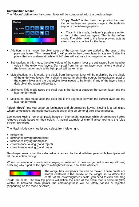
Composition Modes
The “Modes” define how the current layer will be ‘composed’ with the previous layer.
“Copy Mode” is the basic composition between the current layer and previous layers. MediaMaster supports the following options: Copy: In this mode, the layer’s pixels are written on top of the previous layers. This is the default mode. The slider next to the layer preview acts as a transparency control for the layer.
Addition: In this mode, the pixel values of the current layer are added to the ones of the
previous layers. This means that “dark” pixels in the current layer image won’t alter the pixels that are underneath while “light” pixel will saturate the image underneath.
Subtraction: In this mode, the pixel values of the current layer are subtracted from the pixel
value in the underlying layers. Dark pixel from the current layer won’t alter the pixel of the layers underneath while light pixel will darken them.
Multiplication: In this mode, the pixels from the current layer will be multiplied by the pixels
of the underlying layers. For a pixel to appear bright in the output, the equivalent pixel of the current layer and the underlying layer needs to be bright. If any of the layers has a dark pixel, the result will be dark.
Minimum: This mode takes the pixel that is the darkest between the current layer and the
layer underneath
Maximum: This mode takes the pixel that is the brightest between the current layer and the layer underneath.
“Mask Mode” lets you setup up luminance and chrominance keying. Keying is a technique where some pixels are made transparent depending on some of their characteristics. Luminance keying ‘removes’ pixels based on their brightness level while chrominance keying removes pixels based on their colors. A typical example of chrominance keying is the ‘blue screen’ technique. The Mask Mode switches let you select, from left to right: no keying luminance keying (band reject) luminance keying (band pass) chrominance keying (band reject) chrominance keying (band pass) Band reject means that the selected luminance/color band will disappear while band pass will let the selection through. When luminance or chrominance keying is selected, a new widget will show up allowing selecting which part of the spectrum/brightness level should be affected:
The widget has four points that can be moved. These points are always centered in the middle of the widget so, to define the center of the color/brightness scale, you need to click and drag
inside the scale. The two top points will define the zone of the scale that is selected (filter width). In between those points, the color/brightness will be totally passed or rejected (depending on the mode selected).
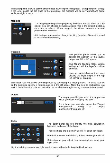
55
The lower points allow to set the smoothness at which pixel will appear / disappear (filter slope). If the lower points too are close to the top points, the masking will be very abrupt and some artifacts might show up.
Mapping
The mapping setting allows projecting the visual and the effect on a 3D object. You can choose between a plane (this is the default mode), a cube and a sphere. When mapped, the video becomes a texture projected on the object. At this stage, you can also change the tiling (number of times the visual is repeated on the object).
Position
The position panel allows you to control the position of the layer’s output in a 2D or 3D space. The square position widget allows setting up both the layer’s position and size. You can use this feature if you want display the layer output in the top left corner for example.
The slider next to it allows zooming in/out by specifying a Z (depth) offset. The three rotaries on the right side specify 3 rotation angles in the 3D space. Note that next to each rotary is a switch that allows the rotary to act either as an absolute angle setting or as a rotation speed.
Output
The output panel let you select the outputs on which you want to display the layer. From here, you can also open the “Output management” dialog (cf. “Output management” on page 99)
Color
The color panel let you modify the hue, saturation, lightness and color of the layer. These settings are extremely useful for color correction. Hue is like a color wheel that you hold before your visual. Saturation let you select how saturated you want your layer to be.
Lightness brings some more light into the layer without affecting the black values.

Red, Green and Blue let you modify the red, green and blue values. Brightness and Contrast can be adapted for each layer separately.
Cropping
The cropping panel let you crop the layer so you can show exactly what you want. You can even select the softness of the edges. This is very useful when working with live camera input.
Sound
The sound panel let you select the volume and pan for each layer.
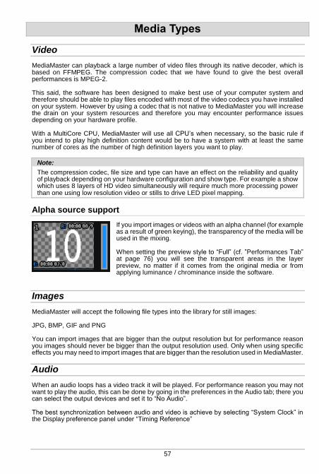
57
Media Types
Video
MediaMaster can playback a large number of video files through its native decoder, which is based on FFMPEG. The compression codec that we have found to give the best overall performances is MPEG-2. This said, the software has been designed to make best use of your computer system and therefore should be able to play files encoded with most of the video codecs you have installed on your system. However by using a codec that is not native to MediaMaster you will increase the drain on your system resources and therefore you may encounter performance issues depending on your hardware profile. With a MultiCore CPU, MediaMaster will use all CPU’s when necessary, so the basic rule if you intend to play high definition content would be to have a system with at least the same number of cores as the number of high definition layers you want to play.
Note:
The compression codec, file size and type can have an effect on the reliability and quality of playback depending on your hardware configuration and show type. For example a show which uses 8 layers of HD video simultaneously will require much more processing power than one using low resolution video or stills to drive LED pixel mapping.
Alpha source support
If you import images or videos with an alpha channel (for example as a result of green keying), the transparency of the media will be used in the mixing. When setting the preview style to “Full” (cf. ”Performances Tab” at page 76) you will see the transparent areas in the layer preview, no matter if it comes from the original media or from applying luminance / chrominance inside the software.
Images
MediaMaster will accept the following file types into the library for still images: JPG, BMP, GIF and PNG You can import images that are bigger than the output resolution but for performance reason you images should never be bigger than the output resolution used. Only when using specific effects you may need to import images that are bigger than the resolution used in MediaMaster.
Audio
When an audio loops has a video track it will be played. For performance reason you may not want to play the audio, this can be done by going in the preferences in the Audio tab; there you can select the output devices and set it to “No Audio”. The best synchronization between audio and video is achieve by selecting “System Clock” in the Display preference panel under “Timing Reference”
Generators
Those are music visualizers that react to the sound of the audio input of your system. Some generators are GPU accelerated effects while others are SWF Flash files. You can create custom generators with Flash, the ArKaos PRO Blog has tutorial articles to get you started.
Effects
Under Mac OS X, MediaMaster allows to use Quartz Composer .qtz files directly, both as sources and effects. The compositions are rendered natively through the fastest available interface. You can import .qtz files as sources simply by adding them to your media library, just like you import any standard movie. Adding Quartz compositions as effects is a little bit trickier because it involves modifying the default fixture to be able to control your effects. It is however possible to achieve this and if you would like to go that way, please contact us and we’ll help you.
Cameras / External Sources
MediaMaster will accept as source any live input that is connected to your computer, as long as it is natively recognized by your system (i.e. without the need to install proprietary drivers or software). Your acquisition device must be compatible with QuickTime under Mac OS X and Direct X under Windows.

59
Libraries
The following settings and preferences are accessed from the “Edit” menu at the top of the software window in Windows OS or on the application menu bar at the top of the screen in Mac OS.
Library Management
Overview and Library Concept
MediaMaster uses a library system of folders and files to help organize your content and allow for quick selection of media as required. The Library is made up of 256 folders, each of which can contain up to 256 media clips or visual effects. No matter what library folder you are in, the visual number 0 is blank – meaning that if you select 0 then no visual is displayed.
Root Folder
At first launch, MediaMaster will ask you to define the root folder for you media library. When you do that, MediaMaster will automatically generate a series of specific folders for pre-installed media content and effects.
Media Folders and Naming Conventions
Within this root folder each media folder needs to be named with a three digit number (001 – 255) followed by an underscore and then the name of the folder. You can name the folder as you wish but spaces are not allowed. For example if you wanted folder 1 to be called assorted clouds the naming convention would be “001_assorted_clouds”
Note:
If the name of the folder or files doesn’t match this format then it will simply be ignored by MediaMaster.
You can also change the name of the folder within the Library Management window by right clicking on the folder and selecting “Rename…” from the pop up menu.

The library window looks like this:
The left pane of the window shows the 256 library folders with the selected folder highlighted in blue. You can scroll through the list and select any of the folders by clicking on its icon. The right pane displays the thumbnails of the visuals contained within the selected folder. There are 255 visuals per folder (the fist one is always considered as an empty slot) and where content doesn’t exist then the thumbnail will display “empty”. You can scroll through the content using the scroll bar on the right side of the window. If you put the mouse pointer over an existing visual, you will see it’s full filename as well as its resolution. All regular content folders are indicated by a folder icon, and display the library number as well as its name. You can add, remove, and duplicate your content inside those folders as you wish either using the computers own filing system or through the library management window in MediaMaster.
The default libraries that are used for specific purposes are at the top end of the library structure (folders 240 onwards) and have different icons relating to their content and purpose. Folder 240 is reserved for Generators. Generators are modules that react to the audio input to generate visuals in much the same way as the visualizer is employed in iTunes or Windows Media Player.
These generators are pixel / particle based and can be great for integration with a live DJ or music set. The sound input from your computer is used to feed these – be it microphone (default) or line input and this is selected in the main software preferences.
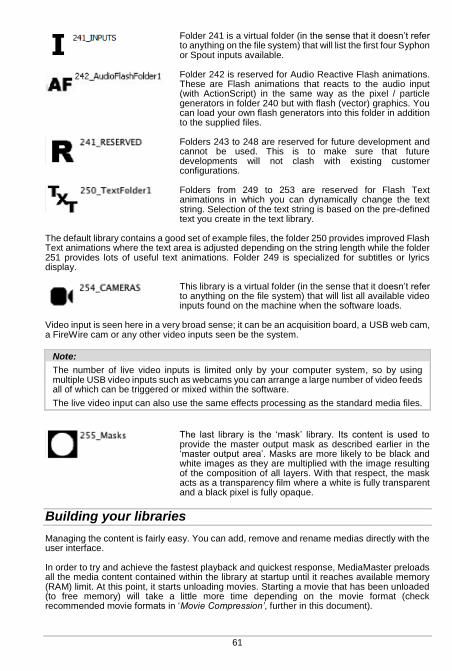
61
Folder 241 is a virtual folder (in the sense that it doesn’t refer to anything on the file system) that will list the first four Syphon or Spout inputs available.
Folder 242 is reserved for Audio Reactive Flash animations. These are Flash animations that reacts to the audio input (with ActionScript) in the same way as the pixel / particle generators in folder 240 but with flash (vector) graphics. You can load your own flash generators into this folder in addition to the supplied files.
Folders 243 to 248 are reserved for future development and cannot be used. This is to make sure that future developments will not clash with existing customer configurations.
Folders from 249 to 253 are reserved for Flash Text animations in which you can dynamically change the text string. Selection of the text string is based on the pre-defined text you create in the text library.
The default library contains a good set of example files, the folder 250 provides improved Flash Text animations where the text area is adjusted depending on the string length while the folder 251 provides lots of useful text animations. Folder 249 is specialized for subtitles or lyrics display.
This library is a virtual folder (in the sense that it doesn’t refer to anything on the file system) that will list all available video inputs found on the machine when the software loads.
Video input is seen here in a very broad sense; it can be an acquisition board, a USB web cam, a FireWire cam or any other video inputs seen be the system.
Note:
The number of live video inputs is limited only by your computer system, so by using multiple USB video inputs such as webcams you can arrange a large number of video feeds all of which can be triggered or mixed within the software.
The live video input can also use the same effects processing as the standard media files.
The last library is the ‘mask’ library. Its content is used to provide the master output mask as described earlier in the ‘master output area’. Masks are more likely to be black and white images as they are multiplied with the image resulting of the composition of all layers. With that respect, the mask acts as a transparency film where a white is fully transparent and a black pixel is fully opaque.
Building your libraries
Managing the content is fairly easy. You can add, remove and rename medias directly with the user interface. In order to try and achieve the fastest playback and quickest response, MediaMaster preloads all the media content contained within the library at startup until it reaches available memory (RAM) limit. At this point, it starts unloading movies. Starting a movie that has been unloaded (to free memory) will take a little more time depending on the movie format (check recommended movie formats in ‘Movie Compression’, further in this document).
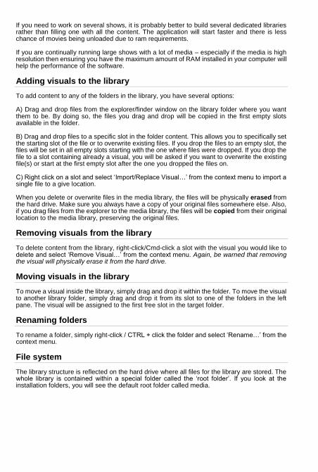
If you need to work on several shows, it is probably better to build several dedicated libraries rather than filling one with all the content. The application will start faster and there is less chance of movies being unloaded due to ram requirements. If you are continually running large shows with a lot of media – especially if the media is high resolution then ensuring you have the maximum amount of RAM installed in your computer will help the performance of the software.
Adding visuals to the library
To add content to any of the folders in the library, you have several options: A) Drag and drop files from the explorer/finder window on the library folder where you want them to be. By doing so, the files you drag and drop will be copied in the first empty slots available in the folder. B) Drag and drop files to a specific slot in the folder content. This allows you to specifically set the starting slot of the file or to overwrite existing files. If you drop the files to an empty slot, the files will be set in all empty slots starting with the one where files were dropped. If you drop the file to a slot containing already a visual, you will be asked if you want to overwrite the existing file(s) or start at the first empty slot after the one you dropped the files on. C) Right click on a slot and select ‘Import/Replace Visual…’ from the context menu to import a single file to a give location. When you delete or overwrite files in the media library, the files will be physically erased from the hard drive. Make sure you always have a copy of your original files somewhere else. Also, if you drag files from the explorer to the media library, the files will be copied from their original location to the media library, preserving the original files.
Removing visuals from the library
To delete content from the library, right-click/Cmd-click a slot with the visual you would like to delete and select ‘Remove Visual…’ from the context menu. Again, be warned that removing the visual will physically erase it from the hard drive.
Moving visuals in the library
To move a visual inside the library, simply drag and drop it within the folder. To move the visual to another library folder, simply drag and drop it from its slot to one of the folders in the left pane. The visual will be assigned to the first free slot in the target folder.
Renaming folders
To rename a folder, simply right-click / CTRL + click the folder and select ‘Rename…’ from the context menu.
File system
The library structure is reflected on the hard drive where all files for the library are stored. The whole library is contained within a special folder called the ‘root folder’. If you look at the installation folders, you will see the default root folder called media.
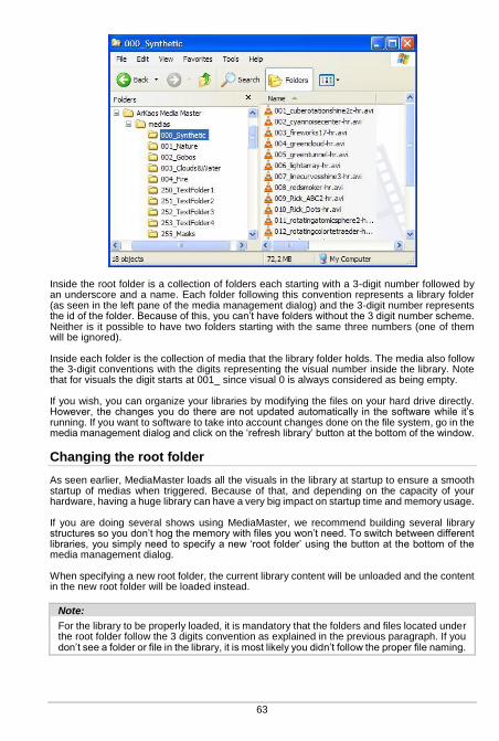
63
Inside the root folder is a collection of folders each starting with a 3-digit number followed by an underscore and a name. Each folder following this convention represents a library folder (as seen in the left pane of the media management dialog) and the 3-digit number represents the id of the folder. Because of this, you can’t have folders without the 3 digit number scheme. Neither is it possible to have two folders starting with the same three numbers (one of them will be ignored). Inside each folder is the collection of media that the library folder holds. The media also follow the 3-digit conventions with the digits representing the visual number inside the library. Note that for visuals the digit starts at 001_ since visual 0 is always considered as being empty. If you wish, you can organize your libraries by modifying the files on your hard drive directly. However, the changes you do there are not updated automatically in the software while it’s running. If you want to software to take into account changes done on the file system, go in the media management dialog and click on the ‘refresh library’ button at the bottom of the window.
Changing the root folder
As seen earlier, MediaMaster loads all the visuals in the library at startup to ensure a smooth startup of medias when triggered. Because of that, and depending on the capacity of your hardware, having a huge library can have a very big impact on startup time and memory usage. If you are doing several shows using MediaMaster, we recommend building several library structures so you don’t hog the memory with files you won’t need. To switch between different libraries, you simply need to specify a new ‘root folder’ using the button at the bottom of the media management dialog. When specifying a new root folder, the current library content will be unloaded and the content in the new root folder will be loaded instead.
Note:
For the library to be properly loaded, it is mandatory that the folders and files located under the root folder follow the 3 digits convention as explained in the previous paragraph. If you don’t see a folder or file in the library, it is most likely you didn’t follow the proper file naming.
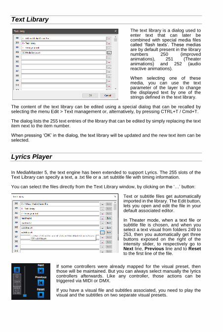
Text Library
The text library is a dialog used to enter text that can later be combined with special media files called ‘flash texts’. These medias are by default present in the library numbers 250 (improved animations), 251 (Theater animations) and 252 (audio reactive animations). When selecting one of these media, you can use the text parameter of the layer to change the displayed text by one of the strings defined in the text library.
The content of the text library can be edited using a special dialog that can be recalled by selecting the menu Edit > Text management or, alternatively, by pressing CTRL+T / Cmd+T. The dialog lists the 255 text entries of the library that can be edited by simply replacing the text item next to the item number. When pressing ‘OK’ in the dialog, the text library will be updated and the new text item can be selected.
Lyrics Player
In MediaMaster 5, the text engine has been extended to support Lyrics. The 255 slots of the Text Library can specify a text, a .txt file or a .srt subtitle file with timing information. You can select the files directly from the Text Library window, by clicking on the ‘…’ button:
Text or subtitle files get automatically imported in the library. The Edit button, lets you open and edit the file in your default associated editor. In Theater mode, when a text file or subtitle file is chosen, and when you select a text visual from folders 249 to 253, then you automatically get three buttons exposed on the right of the intensity slider, to respectively go to Next line, Previous line and to Reset to the first line of the file.
If some controllers were already mapped for the visual preset, then those will be maintained. But you can always select manually the lyrics controllers afterwards. Like any controller, those actions can be triggered via MIDI or DMX. If you have a visual file and subtitles associated, you need to play the visual and the subtitles on two separate visual presets.
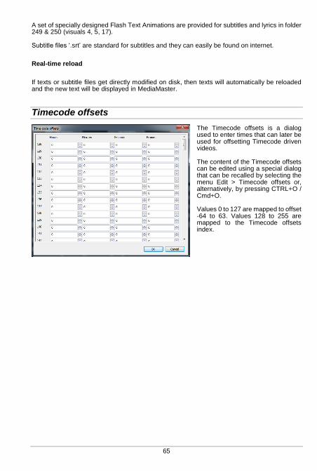
65
A set of specially designed Flash Text Animations are provided for subtitles and lyrics in folder 249 & 250 (visuals 4, 5, 17). Subtitle files ‘.srt’ are standard for subtitles and they can easily be found on internet.
Real-time reload
If texts or subtitle files get directly modified on disk, then texts will automatically be reloaded and the new text will be displayed in MediaMaster.
Timecode offsets
The Timecode offsets is a dialog used to enter times that can later be used for offsetting Timecode driven videos. The content of the Timecode offsets can be edited using a special dialog that can be recalled by selecting the menu Edit > Timecode offsets or, alternatively, by pressing CTRL+O / Cmd+O. Values 0 to 127 are mapped to offset -64 to 63. Values 128 to 255 are mapped to the Timecode offsets index.
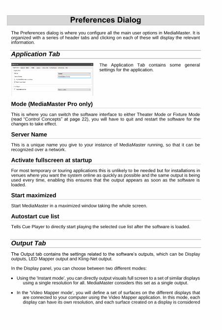
Preferences Dialog
The Preferences dialog is where you configure all the main user options in MediaMaster. It is organized with a series of header tabs and clicking on each of these will display the relevant information.
Application Tab
The Application Tab contains some general settings for the application.
Mode (MediaMaster Pro only)
This is where you can switch the software interface to either Theater Mode or Fixture Mode (read “Control Concepts” at page 22), you will have to quit and restart the software for the changes to take effect.
Server Name
This is a unique name you give to your instance of MediaMaster running, so that it can be recognized over a network.
Activate fullscreen at startup
For most temporary or touring applications this is unlikely to be needed but for installations in venues where you want the system online as quickly as possible and the same output is being used every time, enabling this ensures that the output appears as soon as the software is loaded.
Start maximized
Start MediaMaster in a maximized window taking the whole screen.
Autostart cue list
Tells Cue Player to directly start playing the selected cue list after the software is loaded.
Output Tab
The Output tab contains the settings related to the software’s outputs, which can be Display outputs, LED Mapper output and Kling-Net output. In the Display panel, you can choose between two different modes: Using the 'Instant mode', you can directly output visuals full screen to a set of similar displays
using a single resolution for all. MediaMaster considers this set as a single output.
In the 'Video Mapper mode', you will define a set of surfaces on the different displays that are connected to your computer using the Video Mapper application. In this mode, each display can have its own resolution, and each surface created on a display is considered

67
as a separate output by MediaMaster, meaning that each surface can display a different set of visuals.
Instant mode
The Display panel contains the setup related to the full screen or output mode of the software. As previously stated MediaMaster is designed to be used with at least a two display set-up where displays starting from the 2nd carry the full screen output from the software. As such the first video output is used to display the main interface containing all the previews and parameters while the second video output is used to send the full screen image to a projection hardware. This dialog is used to specify the characteristics of the adapter used for the full screen.
Full screen Display
This specifies on which adapter the full screen will be displayed. Normally the select box should contain at least two entries. If it does not, it means the system doesn’t think you have two-output setup. To correct this, go into the system properties and make sure the display settings are such as you have two displays recognized by the system. Make also sure your displays are setup to provide dual-mode and not cloning. For more discussions on screen setup, see ‘Widescreen & multiscreen presentation’ at page 80.
Resolution
This setting specifies the resolution at which the graphical engine should run. The lower it is, the faster the engine can go and the better the frame rate gets but the lower the quality of the result is. The list of resolutions shown in the drop down menu is dependent on the output device – for example if you are connected to a projector with a maximum resolution of 1024x768 pixels then this will be the maximum you can configure in this box. Use Custom Resolution: use this option if you want to specify manually the internal engine speed to a resolution that is not a display resolution. In the case this option is selected, the ‘Force Resolution’ option will automatically be disabled. Force Resolution: if this option is enabled (default) the software will resize the display output to the engine resolution when going to full screen. Unless specific case, it is often better and more efficient to leave it on. When "Force Resolution" is checked, the output will be displayed full screen. This mode
guaranties the best performances and screen synchronization. When "Force Resolution" is unchecked, the output will be displayed within a top-left
aligned window.
Multi-Display arrangement (Windows only)
It is possible to display the output of MediaMaster across all the displays connected to a graphic card without using the "spanning" feature that is only available under windows XP.
It can be used to avoid going through Matrox DualHead2Go or TrippleHead2Go interfaces if your video card has 2, 3 or more outputs. This feature is available under Windows XP, Vista and Seven. The "Resolution" pop-up menu now proposes multiple-display setups (i.e. "1024x768x2" for a 2048x768 horizontal setup or 1024x1536 vertical setup) in addition to the standard single-display resolutions. The "Multi-Display Arrangement" is there for you to choose the way you want to arrange your monitors. MediaMaster uses this information in combination with the actual Windows display arrangement to determine a correct output.
Note:
Under Mac OS X it is also possible to span the output of MediaMaster over several displays by simply select the display on the top-left and use a custom resolution that will cover the multi-screen setup area.
Soft Edge Span
This option allows you to specify how many projectors you are using to map the whole screen vertically and horizontally. Unless you are using the soft edging function of the software, you should leave this option to 1 for both fields. In the soft edge span the first box is the number of horizontal screens and the second box is the number of vertical screens – so for a triple screen system in a horizontal configuration you would insert 3 and then 1 into the number fields. Please refer to “Soft-Edge” at page 85 for more explanations about setting up and calibrating Soft-Edge span.
Geometric correction & Soft-Edge per output (MediaMaster Pro)
It is possible to warp the output per screen and adapt the soft edge on each side of an output. These settings can be accessed via the "Geometric Correction" button near the soft edge span dimensions on the Display tab of the preferences dialog in MediaMaster Pro. The number and arrangement of the outputs is determined by the soft edge span dimensions.
Geometric correction
Thanks to the Geometric correction you can correct output deformations via a correction grid.

69
The dialog is divided in three main zones: the screen arrangement, the toolbar and the correction grid. Via the clickable screen output arrangement, at the top left of the dialog, it is possible to switch between the correction grids of the different screen outputs. A normal output is represented by a blue rectangle and the overall correction grid is represented by an orange rectangle. With this overall correction grid it is possible to apply a correction over all displays at once. This is especially useful if you are using multiple outputs to project on one curved screen. From the drop-down list on the toolbar, you can choose from four different correction types, namely: No Correction: If you don’t want to apply geometric correction to this screen. In this way
MediaMaster knows that it can bypass the geometric correction process for this screen. Linear: A linearly interpolated grid for straight corrections. Curved: For smooth geometric corrections such as a curved screen. Nurb: A second method for smooth geometric corrections. The correction grid is modified by moving each control points. The control points can be moved with the mouse or with the arrow keys for per pixel precision. Control points can be added with the appropriate buttons on the toolbar and via the keyboard shortcuts (F1-F4). The reset button resets the grid to its original state. The magnetic border makes the screen border ‘sticky’, thus making it easier to correctly position a control point to the border of the screen. The following keyboard / mouse shortcuts are defined for the geometric grid dialog:
Shortcut Action
F1/F2 Add/Remove Horizontal Control Point
F3/F4 Add/Remove Vertical Control Point
R Reset Control Points
M Cycle Through Correction Modes
Arrow Keys Move Control Points Per Pixel
CTRL + A Select All Control Points
CTRL + Click Select Multiple Control Points
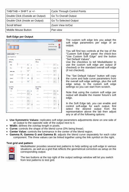
TAB/TAB + SHIFT or +/- Cycle Through Control Points
Double Click (Outside an Output) Go To Overall Output
Double Click (Inside an Output) Go To Selected Output
Scroll Wheel Zoom View In/Out
Middle Mouse Button Pan view
Soft Edge per Output
The custom soft edge lets you adapt the soft edge parameters per edge of an output. You will find two controls at the top of the "Custom Soft Edge" panel: the check-box "Use Custom Soft Edge" and the button "Set Default Values". Use the checkbox to tell MediaMaster to use the custom soft edge per output (if checked) or the standard overall soft edge (if not checked). The "Set Default Values" button will copy the curve and fade curve parameters from the overall soft edge settings, plus the soft edge setup, to the custom soft edge settings so you can start from scratch. Note that using the custom soft edge per output will disable the master fixture's soft edge. In the Soft Edge tab, you can enable and control soft-edge for each output, first select the desired output from the representation above the tab then adjust any or all of the following options:
Use Symmetric Values: replicates soft edge parameters adjustments done on one side of
an output to the opposite side of the output next to it. Width: defines the overlap length in pixels. Curve: controls the shape of the blend curve (0% being linear). Center Value: controls the luminance in the center of the blend region. Gamma R, Gamma G and Gamma B: adjusts the blend curve separately for each color
component. The three values can be linked together using the link symbol on the right.
Test grid and pattern
MediaMaster provides several test patterns to help setting up soft-edge in various situations, as well as a grid that reflects the geometrical correction as setup on the corresponding output. The two buttons at the top right of the output settings window will let you switch from test patterns to test grid.
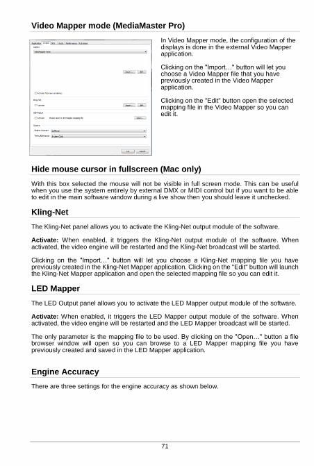
71
Video Mapper mode (MediaMaster Pro)
In Video Mapper mode, the configuration of the displays is done in the external Video Mapper application. Clicking on the "Import…" button will let you choose a Video Mapper file that you have previously created in the Video Mapper application. Clicking on the "Edit" button open the selected mapping file in the Video Mapper so you can edit it.
Hide mouse cursor in fullscreen (Mac only)
With this box selected the mouse will not be visible in full screen mode. This can be useful when you use the system entirely by external DMX or MIDI control but if you want to be able to edit in the main software window during a live show then you should leave it unchecked.
Kling-Net
The Kling-Net panel allows you to activate the Kling-Net output module of the software. Activate: When enabled, it triggers the Kling-Net output module of the software. When activated, the video engine will be restarted and the Kling-Net broadcast will be started. Clicking on the "Import…" button will let you choose a Kling-Net mapping file you have previously created in the Kling-Net Mapper application. Clicking on the "Edit" button will launch the Kling-Net Mapper application and open the selected mapping file so you can edit it.
LED Mapper
The LED Output panel allows you to activate the LED Mapper output module of the software. Activate: When enabled, it triggers the LED Mapper output module of the software. When activated, the video engine will be restarted and the LED Mapper broadcast will be started. The only parameter is the mapping file to be used. By clicking on the "Open…" button a file browser window will open so you can browse to a LED Mapper mapping file you have previously created and saved in the LED Mapper application.
Engine Accuracy
There are three settings for the engine accuracy as shown below.

Minimal is more suited for less powerful hardware. Buffered is the default mode and ensures frame pre-buffering to achieve display
synchronization. Frame Blending: activates the Frame Blending.
Note:
Frame Blending is a technique that allows the engine to interpolate between movie frames whenever it needs to. It’s very useful when slowing down videos a lot, since instead of producing a steppy frame display, the engine will continuously mix from one frame to the other making the transition a lot smoother. It’s also useful when you display movies that have a frame rate that is not ‘coherent’ with your output display.
For example, when using a 60hz display output, you should ideally use only 60/30 fps movies to avoid desyncronisation between the movie frame and when the monitor can display frames. MediaMaster won’t prevent you to play a 25 fps movie, but you might end up with some jitter in the display. Activating Frame Blending will dramatically improve the output quality of the movie in this scenario.
Timing Reference
In order to get the smoothest display possible, MediaMaster defaults to using the main display output as timing reference. This ensures that frames are delivered in timely fashion, synchronized to the display’s vertical blank. However the timing of graphic cards is not always truly accurate: they might advertise 60Hz while actually running slightly over/under that frequency. In most cases this is not really an issue but if you need the movie playback to be perfectly in time (if you synchronize it with some external audio for example, or use movies with audio) you need to be able to use the more accurate time reference of the System clock instead. The selection of the time reference is done through the Combo box under the engine accuracy:
Choose “Display” for a smoother image when exact timing isn’t mandatory or “System Clock” when the video playback speed is critical.
Note:
Display Time Reference privileges video smoothness over audio / video synchronization.
For the audio and video to properly synchronize, it is very important that the timing reference (in display preferences) is set to “System clock” as the inaccurate display frequency reported by the system might cause the audio to drift.
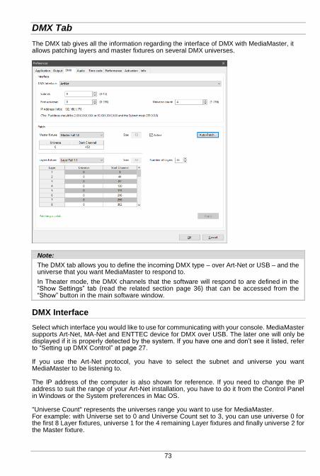
73
DMX Tab
The DMX tab gives all the information regarding the interface of DMX with MediaMaster, it allows patching layers and master fixtures on several DMX universes.
Note:
The DMX tab allows you to define the incoming DMX type – over Art-Net or USB – and the universe that you want MediaMaster to respond to.
In Theater mode, the DMX channels that the software will respond to are defined in the “Show Settings” tab (read the related section page 36) that can be accessed from the “Show” button in the main software window.
DMX Interface
Select which interface you would like to use for communicating with your console. MediaMaster supports Art-Net, MA-Net and ENTTEC device for DMX over USB. The later one will only be displayed if it is properly detected by the system. If you have one and don’t see it listed, refer to “Setting up DMX Control” at page 27. If you use the Art-Net protocol, you have to select the subnet and universe you want MediaMaster to be listening to. The IP address of the computer is also shown for reference. If you need to change the IP address to suit the range of your Art-Net installation, you have to do it from the Control Panel in Windows or the System preferences in Mac OS. "Universe Count" represents the universes range you want to use for MediaMaster. For example: with Universe set to 0 and Universe Count set to 3, you can use universe 0 for the first 8 Layer fixtures, universe 1 for the 4 remaining Layer fixtures and finally universe 2 for the Master fixture.
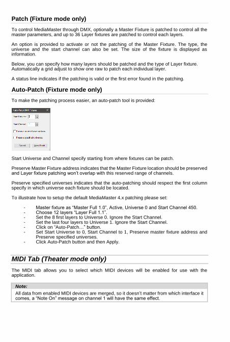
Patch (Fixture mode only)
To control MediaMaster through DMX, optionally a Master Fixture is patched to control all the master parameters, and up to 36 Layer fixtures are patched to control each layers. An option is provided to activate or not the patching of the Master Fixture. The type, the universe and the start channel can also be set. The size of the fixture is displayed as information. Below, you can specify how many layers should be patched and the type of Layer fixture. Automatically a grid adjust to show one raw to patch each individual layer. A status line indicates if the patching is valid or the first error found in the patching.
Auto-Patch (Fixture mode only)
To make the patching process easier, an auto-patch tool is provided:
Start Universe and Channel specify starting from where fixtures can be patch. Preserve Master Fixture address indicates that the Master Fixture location should be preserved and Layer fixture patching won’t overlap with this reserved range of channels. Preserve specified universes indicates that the auto-patching should respect the first column specify in which universe each fixture should be located. To illustrate how to setup the default MediaMaster 4.x patching please set:
- Master fixture as “Master Full 1.0”, Active, Universe 0 and Start Channel 450. - Choose 12 layers “Layer Full 1.1”. - Set the 8 first layers to Universe 0. Ignore the Start Channel. - Set the last four layers to Universe 1. Ignore the Start Channel. - Click on “Auto-Patch…” button. - Set Start Universe to 0, Start Channel to 1, Preserve master fixture address and
Preserve specified universes. - Click Auto-Patch button and then Apply.
MIDI Tab (Theater mode only)
The MIDI tab allows you to select which MIDI devices will be enabled for use with the application.
Note:
All data from enabled MIDI devices are merged, so it doesn’t matter from which interface it comes, a “Note On” message on channel 1 will have the same effect.
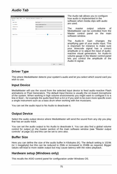
75
Audio Tab
The Audio tab allows you to configure how audio is implemented in the software when media clips with audio are used. The master output volume of MediaMaster can be controlled from the Master control panel on the main software window. The Audio-In Gain changes the amplifying gain of your audio input. This is important for instance to make sure your timecode signal has a correct amplitude or to adjust the input of audio-reactive visual generators. An Audio-In volume gauge in the Master control panel lets you control the amplitude of the Audio-In signal.
Driver Type
This where MediaMaster detects your system’s audio and let you select which sound card you wish to use.
Input Device
MediaMaster will use the sound from the selected input device to feed audio-reactive Flash animations or Pixel Generators. The default Input Device is usually the on-board microphone of the system. When working in high volume environments you might want to configure it to a line-in feed – for example the audio feed from a DJ or if you wish to be even more specific even a single instrument such as a bass drum when working with live musicians. You can set the audio input to No Audio to deactivate it.
Output Device
Select the audio output device where MediaMaster will send the sound from any clip you play that has an audio track. You can set the audio output to No Audio to deactivate it. You can also find a global volume control for output on the master section of the main software window (see “Master output controls” at page 32) and this can be set to zero also.
Buffer Size
Here you can define the size of the audio buffer in Kilobytes (K). The default setting is 1024k (or 1 megabyte) but this can be reduced to 256k or increased to 2048k as required. Bigger values will lead to more stable output but may cause latency with the video playback.
Hardware setup (Windows only)
This recalls the ASIO control panel for configuration under Windows OS.
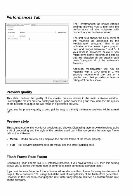
Performances Tab
The Performances tab shows various settings allowing you to fine tune the performance of the software with respect to your hardware set-up. The first field shows the GPU level of the machine as assessed by the MediaMaster software.. This is an indication of the power of your graphic card and ranges between 0 and 5. If your level is anywhere below 3, you might have some features and effects that are disabled as the graphic card doesn’t support all of the software’s features. Although MediaMaster will run on machine with a GPU level of 0, we strongly recommend the use of a graphic card that provides at least a rating of 3 on this scale.
Preview quality
This slider defines the quality of the master preview shown in the main software window. Lowering the master preview quality will speed up the processing and may increase the quality of the full screen output but will result in a pixelated preview. If you set the preview quality to zero (all the way to the left) the master preview will be turned off.
Preview style
This setting control the way layer previews are shown. Displaying layer preview involves quite a bit of processing and the style of the preview used can influence greatly the average frame rate of the software. Media – Media preview only displays the current frame of the visual playing.
Full – Full preview displays both the visual and the effect applied on it.
Flash Frame Rate Factor
Generating Flash effects is a CPU intensive process. If you have a weak CPU then this setting allows you to divide the frame rate of generating flash content by a preset factor. If you set the rate factor to 2 the software will render one flash frame for every two frames of output. This can lower CPU usage but at the cost of losing fluidity of the flash effect generated. However in this scenario changing the rate factor may help to achieve a constant frame rate on the software.
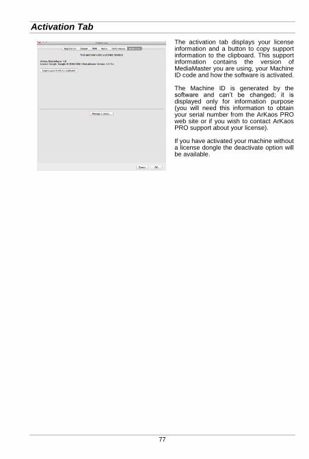
77
Activation Tab
The activation tab displays your license information and a button to copy support information to the clipboard. This support information contains the version of MediaMaster you are using, your Machine ID code and how the software is activated. The Machine ID is generated by the software and can’t be changed; it is displayed only for information purpose (you will need this information to obtain your serial number from the ArKaos PRO web site or if you wish to contact ArKaos PRO support about your license). If you have activated your machine without a license dongle the deactivate option will be available.

Application Menus
File
The “File” menu is only available on a PC. It lets you access to the Preferences dialog and Quit the software. On a Mac, those menus are located in the “MediaMaster” menu.
Note:
To prevent any accidental exit, you can’t exit the software when running in full screen mode.
Edit
Resync to DMX As we’ve seen earlier, even when you slave the server to the DMX console, you can still use the user interface to modify parameters of layers or the master controls. If you do so, the parameter will keep the modified value until this particular parameter is modified from the DMX (i.e. the DMX channel value for that parameter changes). If you wish all parameters to be re-synchronized automatically to the current DMX values, select this entry.
Library Management Brings the media library dialog as discussed in the ‘Media Management’ section earlier in this document.
Text Management Brings the text library dialog as discussed in the ‘Text Library’ section earlier in this document
Output Management Brings the Output dialog as discussed in the ‘Output Management’ section earlier in this document
Show Settings (Theater mode only) Brings the Show Settings dialog as discussed in the ‘Show Settings’ section earlier in this document
Video Mapper Opens the Video mapper application
Kling-Net Mapper Opens the Kling-Net mapper application LED Mapper
Opens the LED mapper application Release Patch (Theater mode only) Release All (Theater mode only) Clear Patch (Theater mode only) Clear Show (Theater mode only)
Display
Toggle full screen This turns on or off the full screen display output. If no external display is connected then the full screen display will be shown on the primary display – replacing the main software window.

79
Help
Documentation Opens the PDF version of this document
Release notes Opens the Release Notes for the current software version
Activation Opens the software activation wizard
ArKaos PRO Website Opens your default Web browser on the ArKaos PRO Home page.
About Opens the ‘About’ dialog
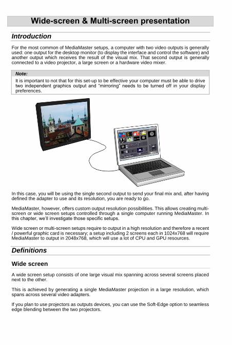
Wide-screen & Multi-screen presentation
Introduction
For the most common of MediaMaster setups, a computer with two video outputs is generally used: one output for the desktop monitor (to display the interface and control the software) and another output which receives the result of the visual mix. That second output is generally connected to a video projector, a large screen or a hardware video mixer.
Note:
It is important to not that for this set-up to be effective your computer must be able to drive two independent graphics output and “mirroring” needs to be turned off in your display preferences.
In this case, you will be using the single second output to send your final mix and, after having defined the adapter to use and its resolution, you are ready to go. MediaMaster, however, offers custom output resolution possibilities. This allows creating multi-screen or wide screen setups controlled through a single computer running MediaMaster. In this chapter, we’ll investigate those specific setups. Wide screen or multi-screen setups require to output in a high resolution and therefore a recent / powerful graphic card is necessary; a setup including 2 screens each in 1024x768 will require MediaMaster to output in 2048x768, which will use a lot of CPU and GPU resources.
Definitions
Wide screen
A wide screen setup consists of one large visual mix spanning across several screens placed next to the other. This is achieved by generating a single MediaMaster projection in a large resolution, which spans across several video adapters. If you plan to use projectors as outputs devices, you can use the Soft-Edge option to seamless edge blending between the two projectors.

81
Multi-screen
The multi-screen setup is the same concept as the wide screen in the sense that it drives several adapters but in this case you end with different visual mixes displayed on each output.
The way it works is that you use the position capabilities of MediaMaster to assign layers to part of the screen, which is divided across the various adapters.
Case studies
In order to explain the different steps to setup MediaMaster to produce a wide screen or multi-screen projection with several displays, let’s examine some common hardware configurations.
Case 1: Dual head graphic card
If you only have a dual head graphic card and would like to achieve multiple outputs, you will need to use both adapters and, since you have no more monitor available left, you will lose the display the interface. If you programmed your show in your DMX console and don’t need visual feedback from the program, this is an option.
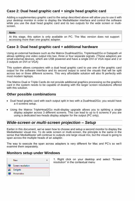
Case 2: Dual head graphic card + single head graphic card
Adding a supplementary graphic card to the setup described above will allow you to use it with your desktop monitor in order to display the MediaMaster interface and control the software while you use the dual head graphic card and its two outputs for the wide screen or multi-screen.
Note:
At this stage, this option is only available on PC. The Mac version does not support accessing more than one graphic adapter.
Case 3: Dual head graphic card + additional hardware
Using an external hardware such as the Matrox DualHead2Go, TripleHead2Go or Datapath x4 allows splitting one video output into two, three or four separate signals. (These adaptors are small external devices, which are USB powered and have a single DVI or VGA input and 2 or 3 outputs on DVI or VGA) This system allows computers with a dual head graphic card to use one of the graphic card output for the software interface and its second output to send the visuals that will be split across two or three different screens. This very affordable solution will also fit perfectly with most modern laptops. The Matrox Dual or Triple Cards do not provide additional graphics processing so the graphics card in the system needs to be capable of dealing with the larger screen resolutions offered with this solution.
Other possible combinations
Dual head graphic card with each output split in two with a DualHead2Go; you would have a 4 screens setup.
Using the Matrox TripleHead2Go multi-display upgrade allows you to splitting a single
display adapter across 3 different screens. This can lead to up to 6 screens if you are using a dedicated two-heads display adapter for the output (PC only).
Wide-screen or multi-screen projection – Setup
Earlier in this document, we’ve seen how to choose and setup a second monitor to display the MediaMaster visual mix. To do wide screen or multi-screen, the principle is the same in the sense that MediaMaster will continue to outputs one large visual mix, but the visual is going to span across the multiple heads of an adapter. The way to execute the span across adapters is very different for Mac and PC’s so we’ll examine them separately.
Monitors setup under Windows
1. Right click on your desktop and select “Screen resolution” in the contextual menu
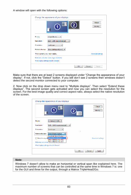
83
A window will open with the following options:
Make sure that there are at least 2 screens displayed under “Change the appearance of your display”. If not, click the “Detect” button. If you still don’t see 2 screens then windows doesn’t detect the second monitor connected to your computer. 2. Now click on the drop down menu next to “Multiple displays”. Then select “Extend these displays”. The second screen gets activated and now you can select the resolution for the screen. For the best image quality and correct aspect-ratio, always select the native resolution of the screen.
Note:
Windows 7 doesn’t allow to make an horizontal or vertical span like explained here. The maximum number of screens that can be controlled at the same time in Windows 7 is: one for the GUI and three for the output, through a Matrox TripleHead2Go.
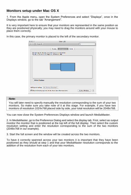
Monitors setup under Mac OS X
1. From the Apple menu, open the System Preferences and select “Displays”, once in the Displays window, go to the tab “Arrangement”. It is very important here to ensure that your monitors are represented in the same position as they are positioned physically; you may need to drag the monitors around with your mouse to place them correctly. In this case, the primary monitor is placed to the left of the secondary monitor.
Note:
You will later need to specify manually the resolution corresponding to the sum of your two monitors. So make sure you take note of it at this stage. For example, if you have two monitors of resolution 1024x768 placed side by side, your total resolution will be 2048x768.
You can now close the System Preferences Displays window and launch MediaMaster. 2. In MediaMaster, go to the Preference Dialog and select the display tab. First, select as output monitor the monitor that is positioned at the top left of the full display. Then select the custom resolution setting and enter the resolution corresponding to the sum of the two monitors (2048x768 in our example). 3. Start the full screen and the window will be created across the two monitors. To have it correctly spanned across your two monitors it is important that they have been positioned as they should at step 1 and that your MediaMaster resolution corresponds to the addition of the resolution from each of your two monitors.
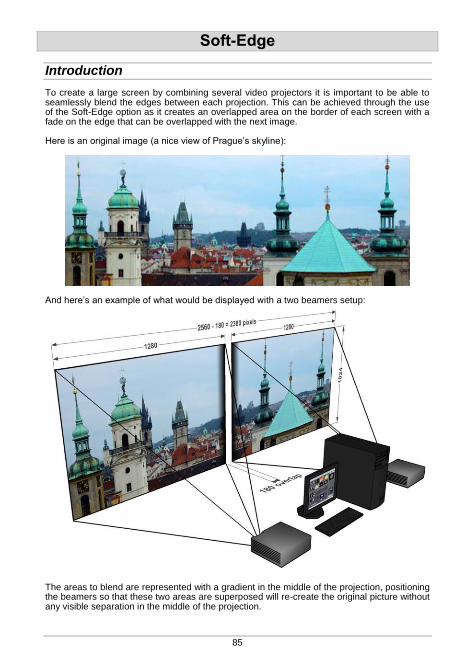
85
Soft-Edge
Introduction
To create a large screen by combining several video projectors it is important to be able to seamlessly blend the edges between each projection. This can be achieved through the use of the Soft-Edge option as it creates an overlapped area on the border of each screen with a fade on the edge that can be overlapped with the next image. Here is an original image (a nice view of Prague’s skyline):
And here’s an example of what would be displayed with a two beamers setup:
The areas to blend are represented with a gradient in the middle of the projection, positioning the beamers so that these two areas are superposed will re-create the original picture without any visible separation in the middle of the projection.
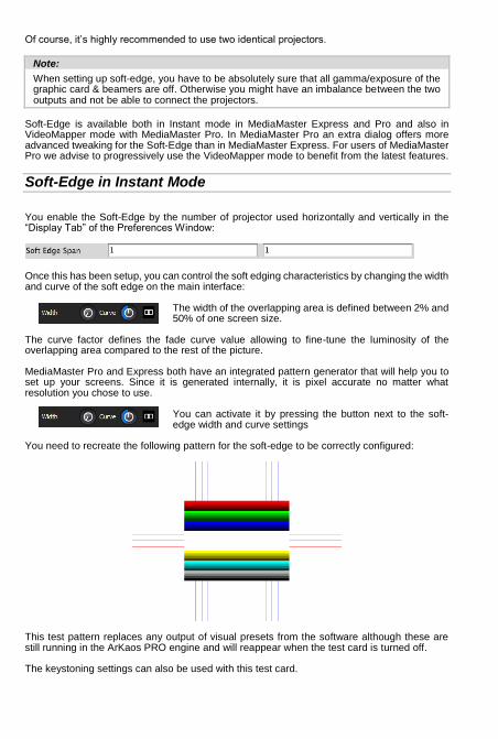
Of course, it’s highly recommended to use two identical projectors.
Note:
When setting up soft-edge, you have to be absolutely sure that all gamma/exposure of the graphic card & beamers are off. Otherwise you might have an imbalance between the two outputs and not be able to connect the projectors.
Soft-Edge is available both in Instant mode in MediaMaster Express and Pro and also in VideoMapper mode with MediaMaster Pro. In MediaMaster Pro an extra dialog offers more advanced tweaking for the Soft-Edge than in MediaMaster Express. For users of MediaMaster Pro we advise to progressively use the VideoMapper mode to benefit from the latest features.
Soft-Edge in Instant Mode
You enable the Soft-Edge by the number of projector used horizontally and vertically in the “Display Tab” of the Preferences Window:
Once this has been setup, you can control the soft edging characteristics by changing the width and curve of the soft edge on the main interface:
The width of the overlapping area is defined between 2% and 50% of one screen size.
The curve factor defines the fade curve value allowing to fine-tune the luminosity of the overlapping area compared to the rest of the picture. MediaMaster Pro and Express both have an integrated pattern generator that will help you to set up your screens. Since it is generated internally, it is pixel accurate no matter what resolution you chose to use.
You can activate it by pressing the button next to the soft-edge width and curve settings
You need to recreate the following pattern for the soft-edge to be correctly configured:
This test pattern replaces any output of visual presets from the software although these are still running in the ArKaos PRO engine and will reappear when the test card is turned off. The keystoning settings can also be used with this test card.

87
If you click again on this button, you will see that there are multiple test patterns appearing. You can choose the one that fits best for your setup.
Calibration
Below are the common steps to setup and calibrate a wide screen with Soft-Edge in MediaMaster in Instant Mode (provided that you have correctly setup your system and your graphics card driver parameters, as explained earlier in this document). Launch MediaMaster in Instant Mode Setup the number of horizontal and vertical screens, and the soft-edge settings in the
“Display tab” of the Preferences Window Import a picture appropriate for calibration and activate it Launch the full screen mode CTRL+F / Cmd +F in MediaMaster)
(At this point, you should have the picture displayed on the two beamers with the soft-edge effect)
Place the beamers correctly so that the edges that blend the seamless area are superposed
Adjust the Curve parameter to obtain the desired luminosity on the overlapping area
Soft-Edge in VideoMapper Mode
When using MediaMaster Pro in VideoMapper Mode, Soft-Edge can be setup between multiple displays and multiple spans directly from within the VideoMapper with all the extra strength offered by the mapper.
When you select a display or a group of display, you can enable Soft-Edge in the tab Correction, as well as Per Display color corrections. In the settings tab you can also turn-on the display of a pattern to help for the precise setup.

Calibration
Below are the common steps to setup and calibrate a wide screen with Soft-Edge in MediaMaster with the Video Mapper. Launch MediaMaster in VideoMapper Mode and run the VideoMapper. Select the display or select a group of displays and setup the resolution and the number of
spans. Activate the Pattern “Geometric Correction” for the setup. Launch the full screen mode CTRL+F / Cmd +F of the VideoMapper. Place the beamers correctly so that the edges that blend the seamless area are
superposed. Turn on Geometric Correction feature and do corrections if needed. Eventually calibrate each display with the Per Display color corrections. Turn on Soft-Edge feature and set the overlap width for each edge requiring Soft-Edge. Adjust the Curve for each edge to make for a smooth transition if needed. Adjust the Center Value to obtain the desired luminosity on the overlapping area.
89
VideoMapper
Concept
The ArKaos VideoMapper is an extension for MediaMaster Pro that allows easy mapping of video onto irregularly shaped surfaces and through multiple outputs. Designed to let you setup mapping projects in a very short time, it makes it incredibly simple to flow visuals around complex objects with just a few clicks. Once you launch the extension, MediaMaster Pro will send the output from each layer to virtual “surfaces” that can be scaled, deformed, and assigned to any physical output. One output can display a full screen visual or a composition of several mapped visuals; output to a video projector and you can map the surfaces to any physical volume (like objects or buildings).
Hardware setup
ArKaos PRO VideoMapper is designed to output video content on any display connected to the computer’s graphical cards. It is advised to connect all the displays to the computer before turning it on. The VideoMapper application will detect the connected displays and let you configure their resolution and refresh frequency individually.
Mapping workflow overview
The VideoMapper application is designed to communicate with MediaMaster. The VideoMapper and MediaMaster can run at the same time on the same computer, so that you can edit the mapping directly with the video content running in MediaMaster. The VideoMapper application is only needed for the edition the video mapping itself, and can be closed once the mapping setup is finished. The mapping will be automatically imported in MediaMaster. The typical workflow is: 1. Connect the displays to the graphics card then turn the computer on. 2. Launch MediaMaster application and switch to the “Video Mapper mode” in the Output
preferences. The application will restart in order to apply the new mode. 3. Launch VideoMapper application. You can also launch it using the “Edit” button in
MediaMaster’s Output preferences. 4. Create a mapping and test it directly with your video content while playing in MediaMaster
or by using a test image. 5. Once the mapping is finished, simply close the Video Mapper application and
MediaMaster will take over the full screen displays.
Important:
The video rendering of MediaMaster occurs on one graphical card. If you would create surfaces on a display that’s on another graphics card, be aware that you may experience reduced performances due to memory transfers between the different graphics cards going through the main memory.
If possible, it’s advised to use the same graphics card to drive all the displays, eventually using a video splitter device. If you absolutely need to use several graphics cards, then you should connect the displays with the biggest resolution to the main graphics card.
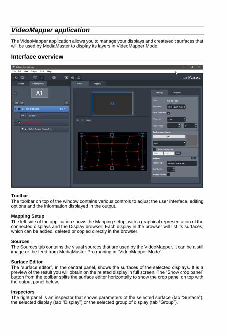
VideoMapper application
The VideoMapper application allows you to manage your displays and create/edit surfaces that will be used by MediaMaster to display its layers in VideoMapper Mode.
Interface overview
Toolbar
The toolbar on top of the window contains various controls to adjust the user interface, editing options and the information displayed in the output.
Mapping Setup
The left side of the application shows the Mapping setup, with a graphical representation of the connected displays and the Display browser. Each display in the browser will list its surfaces, which can be added, deleted or copied directly in the browser.
Sources
The Sources tab contains the visual sources that are used by the VideoMapper, it can be a still image or the feed from MediaMaster Pro running in “VideoMapper Mode”.
Surface Editor
The “surface editor”, in the central panel, shows the surfaces of the selected displays. It is a preview of the result you will obtain on the related display in full screen. The “Show crop panel” button from the toolbar splits the surface editor horizontally to show the crop panel on top with the output panel below.
Inspectors
The right panel is an inspector that shows parameters of the selected surface (tab “Surface”), the selected display (tab “Display”) or the selected group of display (tab “Group”).

91
Toolbar options
Show / hide left panel: shows or hide the left panel with the display browser
so you can have more room to edit your surfaces.
Show / hide crop panel: this will split the surface editor horizontally to show the crop panel on top with the output panel below.
Link grid points: links points between the grind on the crop zone and the grid
on the output zone so that moving a point on one will make the corresponding point move on the other also.
Snap surfaces: surface borders will snap with each other and with the borders of the surface editor
Enable / disable full screen: goes full screen on the active outputs.
Show cursor on full screen: shows the cursor position on the full screen displays
Surface selection flash: the active display will flash each time you select a surface
Surface info on full screen: shows the surface edition objects (surface borders, handles, center and name) on the full screen display.
Setting up displays
Each connected display (as detected by your operating system) is listed in the display browser. Disconnected displays are shown in red. Below each display item appears the list of surfaces (click on the arrow on the left to expand the display item). Each display can be enabled or disabled by clicking on the left check box. Disabled displays won’t go full screen when the global full screen button is activated (the display showing the VideoMapper interface is disabled by default).
Note:
The first letter of identification before the display name (A1, A2, B1, etc.) represents the GPU to which the display is connected. Two displays named A1 and A2 means that they are connected to the same graphics card.
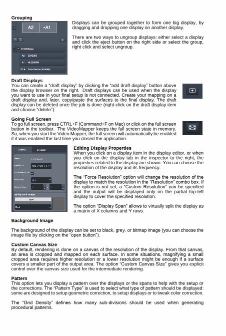
Grouping Displays can be grouped together to form one big display, by dragging and dropping one display on another display. There are two ways to ungroup displays: either select a display and click the eject button on the right side or select the group, right click and select ungroup.
Draft Displays You can create a “draft display” by clicking the “add draft display” button above the display browser on the right. Draft displays can be used when the display you want to use in your final setup is not connected. Create your mapping on a draft display and, later, copy/paste the surfaces to the final display. The draft display can be deleted once the job is done (right-click on the draft display item and choose “delete”).
Going Full Screen To go full screen, press CTRL+F (Command+F on Mac) or click on the full screen button in the toolbar. The VideoMapper keeps the full screen state in memory. So, when you start the Video Mapper, the full screen will automatically be enabled if it was enabled the last time you closed the application.
Editing Display Properties When you click on a display item in the display editor, or when you click on the display tab in the inspector to the right, the properties related to the display are shown. You can choose the resolution of the display and its frequency. The “Force Resolution” option will change the resolution of the display to match the resolution in the “Resolution” combo box. If the option is not set, a “Custom Resolution” can be specified and the output will be displayed only on the partial top-left display to cover the specified resolution. The option “Display Span” allows to virtually split the display as a matrix of X columns and Y rows.
Background Image The background of the display can be set to black, grey, or bitmap image (you can choose the image file by clicking on the “open button”). Custom Canvas Size By default, rendering is done on a canvas of the resolution of the display. From that canvas, an area is cropped and mapped on each surface. In some situations, magnifying a small cropped area requires higher resolution or a lower resolution might be enough if a surface covers a smaller part of the output area. The option “Custom Canvas Size” gives you explicit control over the canvas size used for the intermediate rendering. Pattern This option lets you display a pattern over the displays or the spans to help with the setup or the corrections. The “Pattern Type” is used to select what type of pattern should be displayed: some are designed to setup geometric correction, to setup displays or to tweak color correction. The “Grid Density” defines how many sub-divisions should be used when generating procedural patterns.
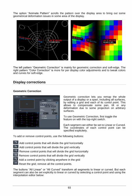
93
The option “Animate Pattern” scrolls the pattern over the display area to bring out some geometrical deformation issues in some area of the display.
The left pattern “Geometric Correction” is mainly for geometric correction and soft-edge. The right pattern “Color Correction” is more for per display color adjustments and to tweak colors and curves for soft-edge.
Display corrections
Geometric Correction
Geometric correction lets you remap the whole output of a display or a span, including all surfaces, by editing a grid and each of its contol point. This allows to compensate some pan, tilt or any deformation due to some projection on arbitrary surfaces. To use Geometric Correction, first toggle the feature on with the top-right switch. Each segment can either be set to Linear or Curved. The coordinates of each control point can be specified explicitely.
To add or remove control points, use the following buttons:
Add control points that will divide the grid horizontally
Add control points that will divide the grid vertically
Remove control points that will divide the grid horizontally
Remove control points that will divide the grid vertically
Add a control point by clicking anywhere in the grid
Reset the grid; remove all the control points. The buttons “All Linear” or “All Curved” transform all segments to linear or curved. But each segment can also be set explicitly to linear or curved by selecting a control point and using the interpolation editor below:
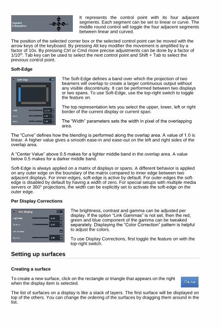
It represents the control point with its four adjacent segments. Each segment can be set to linear or curve. The middle round control will toggle the four adjacent segments between linear and curved.
The position of the selected corner box or the selected control point can be moved with the arrow keys of the keyboard. By pressing Alt key modifier the movement is amplified by a factor of 10x. By pressing Ctrl or Cmd more precise adjustments can be done by a factor of 1/10th. Tab key can be used to select the next control point and Shift + Tab to select the previous control point. Soft-Edge
The Soft-Edge defines a band over which the projection of two beamers will overlap to create a larger continuous output without any visible discontinuity. It can be performed between two displays or two spans. To use Soft-Edge, use the top-right switch to toggle the feature on. The top representation lets you select the upper, lower, left or right border of the current display or current span. The “Width” parameters sets the width in pixel of the overlapping area.
The “Curve” defines how the blending is performed along the overlap area. A value of 1.0 is linear. A higher value gives a smooth ease-in and ease-out on the left and right sides of the overlap area. A “Center Value” above 0.5 makes for a lighter middle band in the overlap area. A value below 0.5 makes for a darker middle band. Soft-Edge is always applied on a matrix of displays or spans. A different behavior is applied on any outer edge on the boundary of the matrix compared to inner edge between two adjacent displays. For inner-edges, soft-edge is active by default. For outer-edges the soft-edge is disabled by default by having a width of zero. For special setups with multiple media servers or 360° projections, the width can be explicitly set to activate the soft-edge on the outer edge. Per Display Corrections
The brightness, contrast and gamma can be adjusted per display. If the option “Link Gammas” is not set, then the red, green and blue component of the gamma can be tweaked separately. Displaying the “Color Correction” pattern is helpful to adjust the colors. To use Display Corrections, first toggle the feature on with the top-right switch.
Setting up surfaces
Creating a surface To create a new surface, click on the rectangle or triangle that appears on the right when the display item is selected. The list of surfaces on a display is like a stack of layers. The first surface will be displayed on top of the others. You can change the ordering of the surfaces by dragging them around in the list.

95
Editing Surface Properties When you select a surface, its properties are displayed in the inspector on the right.
You can modify geometrical parameters by editing the surface directly in the graphical editor (for example modify the width or the height of a rectangle by dragging the middle handles of the rectangle) or enter numerical values in the inspector.
The X and Y parameters are the coordinates of the surface. This position is by default the top-left corner for rectangles and the center for triangles. If the option “Display Top Left Coordinates” is unchecked in the view menu, the position of the rectangles will be centered. The R parameter is the rotation of the surface. The rotation can also be modified by dragging the rotation handle in the graphical editor. The other parameters depend on which surface you are editing. For Triangles you can edit the position of the three corners of the triangle (parameter X-Y
in the inspector). For Rectangles you can modify the width and the height of the rectangle (parameter W-H
in the inspector).
The rectangle can also be deformed using a grid pattern. To enable the grid, check the option “Edit Grid” in the inspector When the grid is enabled each control point of the grid can be dragged separately. To add or remove control points, use the buttons just below the edit grid option.
Add control points that will divide the grid horizontally
Add control points that will divide the grid vertically
Remove control points that will divide the grid horizontally
Remove control points that will divide the grid vertically
Add a control point by clicking anywhere in the grid
Reset the grid; remove all the control points.
The interpolation between the control points can be linear or curved. To set the interpolation for all the control points of the grid, use the interpolation combo box.
To set the interpolation separately for each control point, select a control point in the graphical editor, then the interpolation editor appears. It represents the control point with its four adjacent segments. Each segment can be set to linear or curve.
The position of the selected corner box or the selected control point can be edited with the arrow keys of the keyboard. To move the point of 20 pixels, press Alt while moving the point. To move the point of 0.05 pixels, press Ctrl (Cmd on mac) while moving the point.
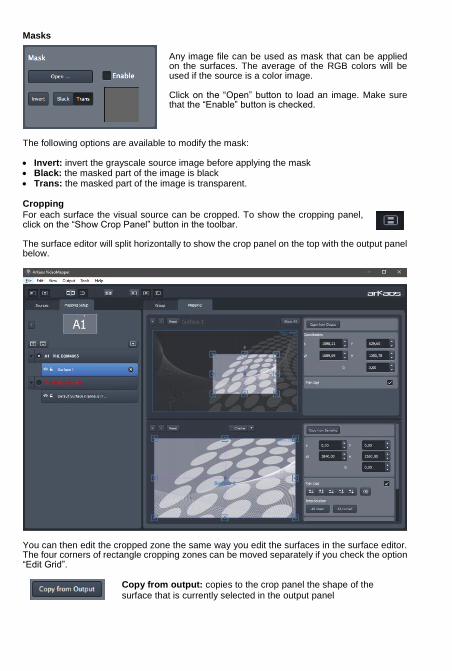
Masks
Any image file can be used as mask that can be applied on the surfaces. The average of the RGB colors will be used if the source is a color image. Click on the “Open” button to load an image. Make sure that the “Enable” button is checked.
The following options are available to modify the mask: Invert: invert the grayscale source image before applying the mask Black: the masked part of the image is black Trans: the masked part of the image is transparent.
Cropping
For each surface the visual source can be cropped. To show the cropping panel, click on the “Show Crop Panel” button in the toolbar. The surface editor will split horizontally to show the crop panel on the top with the output panel below.
You can then edit the cropped zone the same way you edit the surfaces in the surface editor. The four corners of rectangle cropping zones can be moved separately if you check the option “Edit Grid”.
Copy from output: copies to the crop panel the shape of the surface that is currently selected in the output panel

97
Copy from sampling: copies to the output panel the shape of the surface that is currently selected in the crop panel
The Copy from sampling/output feature is very handy when you have to deal with complex shapes made of several surfaces, it will help to keep a final image that won’t get distorted.
The Show All button allows seeing the cropping zones corresponding to all the surfaces of the display. This option is useful if you want “cut” a visual into several surfaces.
Visual Sources
The visual sources of the VideoMapper can be found under the “Sources” tab in the left pane, next to the Mapping setup.
Visual sources can be an image or the feed from MediaMaster Pro running in “VideoMapper Mode”. If MediaMaster Pro is running, the source will automatically switch to MediaMaster.
To add an image to the list of sources, click on the “Load Image” button above the list. Double click on an item of the list to select that source.
Export and Import of Mapping Files
The VideoMapper constantly saves the mapping file internally. You can export your mapping using the “Export” option in the “File” menu. The exported file (.vmp file) contains the configuration of the output groups of MediaMaster as well. You can import external mappings using the “Import” option in the “File” menu.

Key Bindings
Sampling Editor Shortcut Keys Middle Mouse Button : Pan View Scroll Wheel : Zoom View In/Out Shift + Left Mouse Click : Multi selection Shift + Surface Rescale : Aspect-ratio Rescale Arrow Keys : Move Selected Surface by 1 pixel Alt + Arrow Keys : Move Selected Surface by 10 pixels Ctrl (Cmd on Mac) + Arrow Keys : Move Selected Surface by 0.1 pixel Ctrl (Cmd on Mac) + i : Hide All Surfaces Except The Selected One Ctrl (Cmd on Mac) + shift + i : Show All Surfaces Grid Surface Shortcut Keys R : Reset Grid F1 : Adds Horizontal Control Points F2 : Removes Horizontal Control Points F3 : Adds Vertical Control Points F4 : Removes Vertical Control Points F5 : Adds a Control Point Anywhere F6 : Changes Grid Interpolation Type F7 : Toggles Control Point Interpolation Type TAB + Arrow Keys : Change Control Point Selection Right Click Inside Grid: Selection Box Around Control Points Application Shortcut Keys Ctrl (Cmd on Mac) + I : Move The Video Mapper Window To Cursor Position Ctrl (Cmd on Mac) + G : Surface Snap Ctrl (Cmd on Mac) + E : Show crop panel Ctrl (Cmd on Mac) + F : Go full screen Ctrl (Cmd on Mac) + N : New Mapping Ctrl (Cmd on Mac) + O : Import a Mapping File Ctrl (Cmd on Mac) + Shift + S : Export a Mapping File Ctrl (Cmd on Mac) + P : Open Preference Dialog Ctrl (Cmd on Mac) + Q : Quit The Application
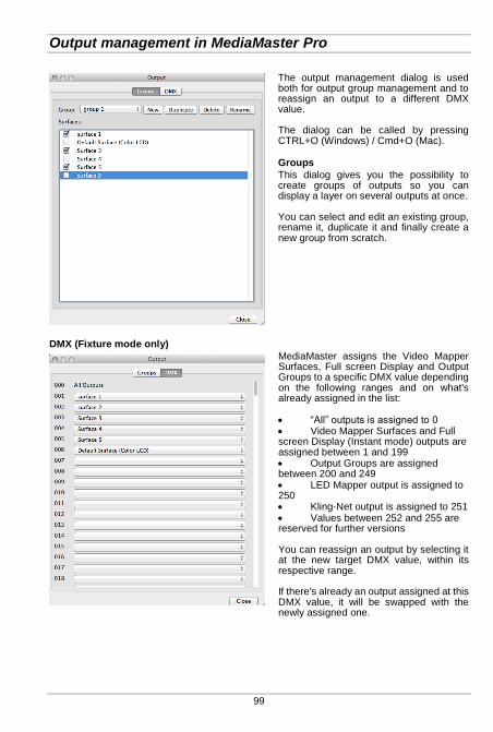
99
Output management in MediaMaster Pro
The output management dialog is used both for output group management and to reassign an output to a different DMX value. The dialog can be called by pressing CTRL+O (Windows) / Cmd+O (Mac).
Groups
This dialog gives you the possibility to create groups of outputs so you can display a layer on several outputs at once. You can select and edit an existing group, rename it, duplicate it and finally create a new group from scratch.
DMX (Fixture mode only)
MediaMaster assigns the Video Mapper Surfaces, Full screen Display and Output Groups to a specific DMX value depending on the following ranges and on what's already assigned in the list: “All” outputs is assigned to 0 Video Mapper Surfaces and Full screen Display (Instant mode) outputs are assigned between 1 and 199 Output Groups are assigned between 200 and 249 LED Mapper output is assigned to 250 Kling-Net output is assigned to 251 Values between 252 and 255 are reserved for further versions You can reassign an output by selecting it at the new target DMX value, within its respective range. If there's already an output assigned at this DMX value, it will be swapped with the newly assigned one.

MediaHub
Concept
MediaMaster 5 introduces a new tool, the MediaHub, to make synchronization of content as simple as possible between multiple servers. Typical use cases are:
Deploying new content on a set of Media servers. Doing a backup of all the content of a server. Synchronizing latest content from a laptop to a server just before a show. Remotely updating content on a server that is hard to reach. Comparing content of multiple servers and making sure they are in sync. Remotely checking the status of a set of servers.
Getting Started
MediaHub is an application that can run on a PC or on a Mac, and communicates over a wired or wireless network to one or more running instances of MediaMaster 5. MediaHub can communicate with MediaMaster running on the same computer, but installing MediaMaster on a computer is not mandatory to start MediaHub. To get started, MediaMaster 5 should be started on one or more computers or servers and reachable over a network. Then you should start the MediaHub application. Then select two servers you want to interact with through the dropdown above the left and the right panels. Then select directories or files that you want to synchronize in the left panel. Click the right arrow in the middle of the screen to start the synchronization to the other server.
User Interface
Main View
The main view shows:
A toolbar
A left and a right panel showing the content of two servers
Synchronization arrows buttons and a synchronization status
Actions to perform on each server
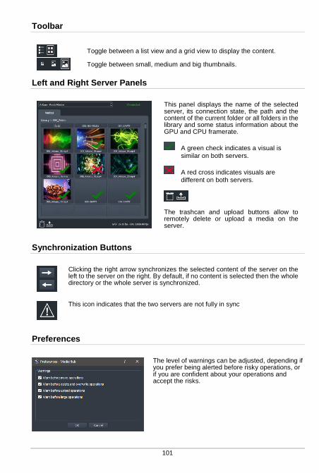
101
Toolbar
Toggle between a list view and a grid view to display the content.
Toggle between small, medium and big thumbnails.
Left and Right Server Panels
This panel displays the name of the selected server, its connection state, the path and the content of the current folder or all folders in the library and some status information about the GPU and CPU framerate.
A green check indicates a visual is
similar on both servers.
A red cross indicates visuals are different on both servers.
The trashcan and upload buttons allow to remotely delete or upload a media on the server.
Synchronization Buttons
Clicking the right arrow synchronizes the selected content of the server on the left to the server on the right. By default, if no content is selected then the whole directory or the whole server is synchronized.
This icon indicates that the two servers are not fully in sync
Preferences
The level of warnings can be adjusted, depending if you prefer being alerted before risky operations, or if you are confident about your operations and accept the risks.
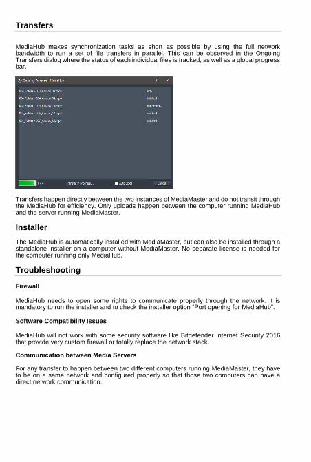
Transfers
MediaHub makes synchronization tasks as short as possible by using the full network bandwidth to run a set of file transfers in parallel. This can be observed in the Ongoing Transfers dialog where the status of each individual files is tracked, as well as a global progress bar.
Transfers happen directly between the two instances of MediaMaster and do not transit through the MediaHub for efficiency. Only uploads happen between the computer running MediaHub and the server running MediaMaster.
Installer
The MediaHub is automatically installed with MediaMaster, but can also be installed through a standalone installer on a computer without MediaMaster. No separate license is needed for the computer running only MediaHub.
Troubleshooting
Firewall
MediaHub needs to open some rights to communicate properly through the network. It is mandatory to run the installer and to check the installer option “Port opening for MediaHub”.
Software Compatibility Issues
MediaHub will not work with some security software like Bitdefender Internet Security 2016 that provide very custom firewall or totally replace the network stack. Communication between Media Servers For any transfer to happen between two different computers running MediaMaster, they have to be on a same network and configured properly so that those two computers can have a direct network communication.

103
Pixel Mapping over Kling-Net
Concepts
Kling-Net is a protocol designed to simplify the setup and operation of display devices such as LED devices. Those LED devices are connected to a computer through a standard Ethernet network.
The purpose of Kling-Net is: ● To allow the connection of display devices to a computer through an automatic configuration ● To dynamically configure the network by assigning IP numbers to the LED devices ● To ensure a perfect time synchronization of many display devices ● To avoid using expensive hardware video converters usually needed to send video to
display devices ● To allow creating a heterogeneous network of display devices made by different
manufacturer and controlled by a Theater computer ● To add some intelligence into display devices in order to allow device auto configuration With Kling-Net, display devices and network installations become straightforward to setup. Kling-Net is independent of DMX, Art-Net or E1.31 (also called Streaming ACN) protocols.
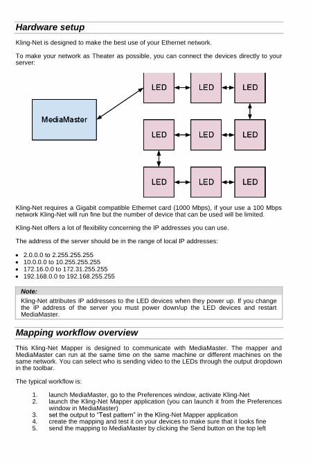
Hardware setup
Kling-Net is designed to make the best use of your Ethernet network. To make your network as Theater as possible, you can connect the devices directly to your server:
Kling-Net requires a Gigabit compatible Ethernet card (1000 Mbps), if your use a 100 Mbps network Kling-Net will run fine but the number of device that can be used will be limited. Kling-Net offers a lot of flexibility concerning the IP addresses you can use. The address of the server should be in the range of local IP addresses: 2.0.0.0 to 2.255.255.255 10.0.0.0 to 10.255.255.255 172.16.0.0 to 172.31.255.255 192.168.0.0 to 192.168.255.255
Note:
Kling-Net attributes IP addresses to the LED devices when they power up. If you change the IP address of the server you must power down/up the LED devices and restart MediaMaster.
Mapping workflow overview
This Kling-Net Mapper is designed to communicate with MediaMaster. The mapper and MediaMaster can run at the same time on the same machine or different machines on the same network. You can select who is sending video to the LEDs through the output dropdown in the toolbar. The typical workflow is:
1. launch MediaMaster, go to the Preferences window, activate Kling-Net 2. launch the Kling-Net Mapper application (you can launch it from the Preferences
window in MediaMaster) 3. set the output to “Test pattern” in the Kling-Net Mapper application 4. create the mapping and test it on your devices to make sure that it looks fine 5. send the mapping to MediaMaster by clicking the Send button on the top left
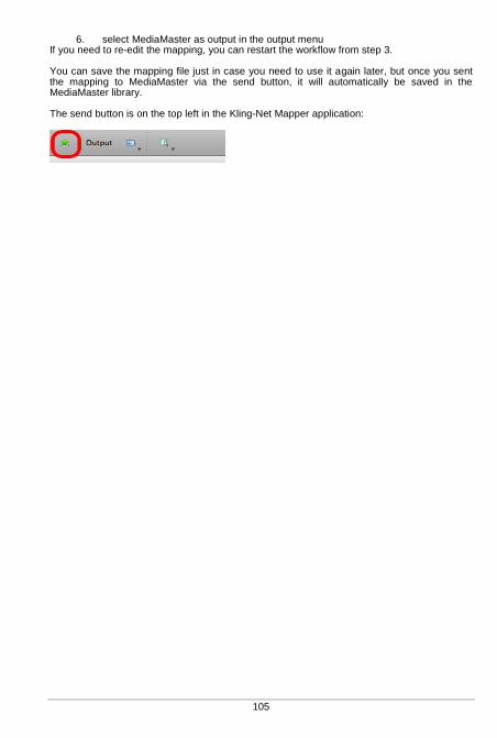
105
6. select MediaMaster as output in the output menu If you need to re-edit the mapping, you can restart the workflow from step 3. You can save the mapping file just in case you need to use it again later, but once you sent the mapping to MediaMaster via the send button, it will automatically be saved in the MediaMaster library. The send button is on the top left in the Kling-Net Mapper application:

Kling-Net Mapper application
Overview
The Kling-Net Mapper application is where you define areas of the MediaMaster video output that will be sent to the LED devices.
The video output is represented by the mapper canvas. The connected devices are listed in the left panel. To add a device in the setup, simply drag and drop a device on the canvas. It will automatically create a “mapping rectangle”. The area included in the rectangle will be grabbed and sent to the corresponding device. The application has been designed to be simple and easy to use. Each manipulation of device mapping are immediately reflected on the real LED device. This is very handy because some setups can be very complex and driving many devices. It also makes the mapping process in Kling-Net Mapper as seamless as possible. The mapper should primarily be used for calibration, so background images used in the canvas are still test pattern images. You can also use a screen grabber to preview the result on moving images. Once you’ve created your mapping, MediaMaster will use it to feed the LEDs with video streams, movies, text, effects or generated content.
Connected Nodes
The “Connected Nodes” panel shows the list of Kling-Net Nodes like the Kling-Force products. The toggle with the eye icon tells if the devices connected on that node should appear in the list of connected devices. For Kling-Force products, the three part number between round brackets indicates the Firmware version. If Kling-Net Mapper embeds a more recent version of the Firmware, the Kling-Force device will be automatically updated.
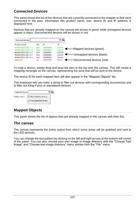
107
Connected Devices
This panel shows the list of the devices that are currently connected to the mapper or that were connected in the past. Information like product name, size, device ID and IP address is displayed here. Devices that are already mapped on the canvas are shown in green while unmapped devices appear in black. Disconnected devices will be shown in red.
To map a device, simply drag and drop the item in the list onto the canvas. This will create a mapping rectangle on the canvas, representing the area that will be sent to the device. The device ID for each mapped item will also appear in the “Mapped Objects” list. The dropdown lets you enter a string to filter out devices with corresponding occurrences and to filter out Kling-Force or standalone devices.
Mapped Objects
This panel shows the list of objects that are already mapped in the canvas with their IDs.
The canvas
The canvas represents the entire output from which some areas will be grabbed and sent to the LED devices. You can change the test pattern by clicking on the left and right arrows at the bottom-left corner of the panel. You can also choose your own image or image directory with the “Choose Test Image” and “Choose test image directory” menu entries from the “File” menu.
Mapped devices (green) Unmapped devices (black)
Disconnected devices (red)

The size of the canvas is the size that will be used to render animation clips in MediaMaster. You can change it by using the “Canvas Size” menu entry in the “Canvas” menu. You can also automatically adjust the canvas size to the selected devices by using the “Crop To Selection” menu entry. To edit mapping properties for devices, click on a mapping rectangle on the canvas. Properties will appear in the object inspector, at the bottom of the screen. To zoom in the canvas, use the mouse wheel on PC or Cmd + mouse scroll on Mac. To pan, press the middle mouse button and move the mouse on PC or use vertical and horizontal mouse scroll on Mac.
Dividing and Splitting
Kling-Net devices can be divided or split in the Kling-Net Mapper. Each part can then be mapped independently even if they are connected through only one Kling-Net connection.
Dividing
A typical use case would be for a set of LED strips that are exposed as one rectangular Kling-Net device. By using the divisor field in the device properties and entering the number of LED Strips, each individual LED strip can be mapped with the correct LED resolution.
Splitting
Each individual strip can also be split after any number of LEDs to create multi-segment strips.
Rotate handle: rotates the mapping rectangle
Select test pattern
Resize handle: resize the mapping rectangle
Mapping rectangle
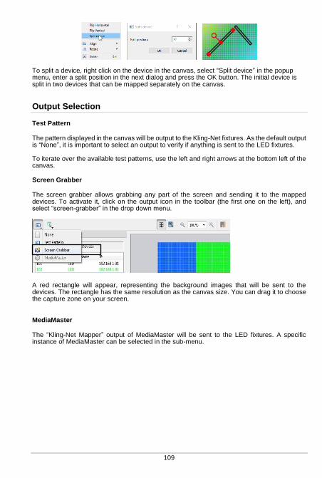
109
To split a device, right click on the device in the canvas, select “Split device” in the popup menu, enter a split position in the next dialog and press the OK button. The initial device is split in two devices that can be mapped separately on the canvas.
Output Selection
Test Pattern
The pattern displayed in the canvas will be output to the Kling-Net fixtures. As the default output is “None”, it is important to select an output to verify if anything is sent to the LED fixtures. To iterate over the available test patterns, use the left and right arrows at the bottom left of the canvas.
Screen Grabber
The screen grabber allows grabbing any part of the screen and sending it to the mapped devices. To activate it, click on the output icon in the toolbar (the first one on the left), and select “screen-grabber” in the drop down menu.
A red rectangle will appear, representing the background images that will be sent to the devices. The rectangle has the same resolution as the canvas size. You can drag it to choose the capture zone on your screen.
MediaMaster
The “Kling-Net Mapper” output of MediaMaster will be sent to the LED fixtures. A specific instance of MediaMaster can be selected in the sub-menu.

Templates
Templates are the easiest way to map several devices of the same size in a grid. To create a template click on the “Create Template” button at the bottom of the mapped devices list. This will open the Template Creation dialog box.
The Template Creation dialog box shows a list of available sizes on the left. Chose the size of the devices you want to map in the list. The dimensions parameter modifies the number of devices you can map on the template.
To map devices on the template, double click on it or click on the template map mode icon in the toolbar. When the map mode is activated, everything is frozen in the graphical editor, the only thing you can do is drag and drop devices on the template. You can only drag and drop devices with the right size, as defined in the template creation dialog. When you’re ready with the mapping, double click out of the template to come back to the normal mode. Devices mapped into a template are “attached” to it. Therefore it is easy to edit a set of devices, which belong to a template. A supplementary parameter is available for templates in the object inspector: “interspaces”. It allows you to define interspaces between each device in the template.
Select a device size
Select the template size

111
Preferences
“Use Bilinear Filtering” indicates that any sampling done between two pixels in the canvas will be interpolated using bilinear interpolation. If “Use Center for Position” is set, then the displayed and edited position of a fixture corresponds to the center of the fixture rectangle. Also rotations are done around the center which might feel more natural. If “Use Center for Position” is not set, then the displayed and edited position of a fixture corresponds to the first LED on the top left corner of the fixture rectangle. Also rotations are done around this first LED which is more appropriate to set vertical fixtures to some precise (x,y) coordinates. This mode is better to setup pixel perfect mapping because for even pixel dimensions, the center would be in the middle of two pixels.
Pixel Perfect Mappings
For pixel perfect mappings, unset options “Use Bilinear Filtering” and “Use Center for Position” in the preferences. Make sure your devices are mapped with their genuine size. Only use whole numbers for positions and only multiple of 90° for rotations.
How to Display LED mappings from MediaMaster
MediaMaster uses a unique mapping file that is stored to a precise location in the Library folder. If you use the New, Open, Save or Save As file operations in the Kling-Net Mapper, the current mapping will not automatically get used by MediaMaster. Below are the different ways to tell MediaMaster to use the new edited mapping.
While the Kling-Net Mapper is running.
If you have created and edited a mapping and want to display it in MediaMaster you must do two actions: 1. Send the mapping to MediaMaster To do this you can simply use the send button on the top left of the interface. Another way is to archive your mapping by saving it to disk and from the preference of MediaMaster import the mapping file. Using the send button is the fastest way. The send button is top left in the Kling-Net Mapper application:
2. Switch the output to MediaMaster From the output menu, switch the video output back to MediaMaster. While the output is set to MediaMaster you can continue to edit your mapping and use the send button to update the output in MediaMaster.
Note:
You can read the section “Output Tab” at page 66 of this manual to get more details about the configuration of Kling-Net in MediaMaster.

While Kling-Net Mapper is not running.
If no Kling-Net Mapper is running, then when MediaMaster starts it will send output to the Kling-Net devices if Kling-Net is activated. If you already loaded the mapping in a previous session, MediaMaster will restore the mapping automatically. If you want to load a new mapping file you must use the Kling-Net import button in the “Output Tab” in the Preferences of MediaMaster.
113
Pixel Mapping over DMX
MediaMaster Express and Pro can also be used to drive LED, dimmers or other color changing devices over DMX in addition to sending high resolution video content to conventional projection or display devices with DVI, VGA or S-Video input. In order to use the pixel mapping output over DMX you must first build a “mapping file”. This is created using the ArKaos PRO LED Mapper software, which is installed alongside the main MediaMaster program and allows you to configure what type of LED fixtures you are using, their DMX addresses and what pixels of your output screen they are related to. The LED mapping samples the video output buffer and as such full screen output must be enabled for pixel mapping to work. The LED Mapper has no software limitation. You can control as many LED fixtures as you want within the limit of the 256 DMX universes. We will explain here how to create the mapping file that describes your network of LED devices.
With the mapping file created and loaded into MediaMaster, the software will output DMX values for each pixel that has been mapped based on the color and intensity of that pixel in your master video output.
This output of DMX can be done SIMULTANEOUSLY with the main video output – allowing you to use DMX controlled color mixing fixtures alongside your display devices.
For example you may have a central projection display in the middle of the stage and surround it with LED color mixing tubes which would also respond to the same content and be controlled via MediaMaster. The LED Mapper software includes profiles for many of the leading LED fixtures currently on the market.
Note:
By default the LED Mapper is not activated, for more information on how to activate LED Output in MediaMaster, read the section “Output Tab” from the Preferences Dialog at page 66.
LED Mapper 3 introduction
Overview of the new features
LED Mapper 3 is a major upgrade from the LED Mapper that was included with the previous version of MediaMaster, the main new features are:
Support of unicast to optimize your network
Auto-discovery of Art-Net nodes for an easier setup
LED Mapper and MediaMaster can run simultaneously
Reworked toolbar with new network selector and activity LEDs
LED Mapper extension icon
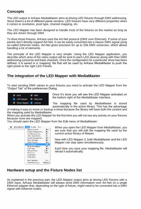
Concepts
The LED output in ArKaos MediaMaster aims at driving LED fixtures through DMX addressing. Since there’s a lot of different panel vendors, LED fixtures have very different properties when it comes to resolution, pixel type, channel mapping, etc. The LED Mapper has been designed to handle most of the fixtures on the market as long as they are driven through DMX. To drive those fixtures, ArKaos uses the Art-Net protocol (DMX over Ethernet). If some of your panels don’t directly support Art-Net, it can be easily converted into a classic DMX signal using so-called Ethernet nodes. Art-Net gives provision for up to 256 DMX universes, which allows handling a lot of elements. The principle of the LED Mapper is very simple: Using the LED Mapper application, you describe which area of the video output will be sent to each LED devices along with their DMX addressing (universe and base channel). Once the configuration for a particular show has been defined, it is saved in a ‘mapping’ file that will be used by ArKaos MediaMaster to push the right pixels to the right LED Panels.
The integration of the LED Mapper with MediaMaster
To start sending DMX values to your fixtures you need to activate the LED Mapper from the “Output Tab” of the preferences Dialog.
Once it’s done you will see the LED Mapper activated on the bottom right of the MediaMaster interface. The mapping file used by MediaMaster is stored automatically in the active library. This has the advantage
of making it easy to move or backup a show because the library will have both the content and the mapping used by MediaMaster. When you activate the LED Mapper for the first time you will not see any activity on your fixtures because none are mapped. You should open the LED Mapper from the Edit menu of MediaMaster:
When you open the LED Mapper from MediaMaster, you are sure that you will edit the mapping file used by the current active library of Master. New with LED Mapper 3, both MediaMaster and the LED Mapper can stay open simultaneously. Each time you save your mapping file, MediaMaster will reload it automatically.
Hardware setup and the Fixture Nodes list
As explained in the previous part, the LED Mapper output aims at driving LED fixtures with a DMX input. ArKaos MediaMaster will always send DMX information over Art-Net on a single Ethernet adapter that, depending on the type of fixture, might need to be converted into a DMX signal with Ethernet nodes.
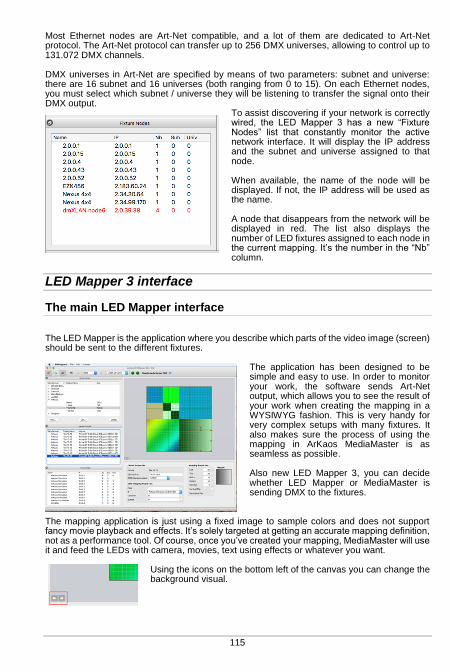
115
Most Ethernet nodes are Art-Net compatible, and a lot of them are dedicated to Art-Net protocol. The Art-Net protocol can transfer up to 256 DMX universes, allowing to control up to 131.072 DMX channels. DMX universes in Art-Net are specified by means of two parameters: subnet and universe: there are 16 subnet and 16 universes (both ranging from 0 to 15). On each Ethernet nodes, you must select which subnet / universe they will be listening to transfer the signal onto their DMX output.
To assist discovering if your network is correctly wired, the LED Mapper 3 has a new “Fixture Nodes” list that constantly monitor the active network interface. It will display the IP address and the subnet and universe assigned to that node. When available, the name of the node will be displayed. If not, the IP address will be used as the name. A node that disappears from the network will be displayed in red. The list also displays the number of LED fixtures assigned to each node in the current mapping. It’s the number in the “Nb” column.
LED Mapper 3 interface
The main LED Mapper interface
The LED Mapper is the application where you describe which parts of the video image (screen) should be sent to the different fixtures.
The application has been designed to be simple and easy to use. In order to monitor your work, the software sends Art-Net output, which allows you to see the result of your work when creating the mapping in a WYSIWYG fashion. This is very handy for very complex setups with many fixtures. It also makes sure the process of using the mapping in ArKaos MediaMaster is as seamless as possible. Also new LED Mapper 3, you can decide whether LED Mapper or MediaMaster is sending DMX to the fixtures.
The mapping application is just using a fixed image to sample colors and does not support fancy movie playback and effects. It’s solely targeted at getting an accurate mapping definition, not as a performance tool. Of course, once you’ve created your mapping, MediaMaster will use it and feed the LEDs with camera, movies, text using effects or whatever you want.
Using the icons on the bottom left of the canvas you can change the background visual.
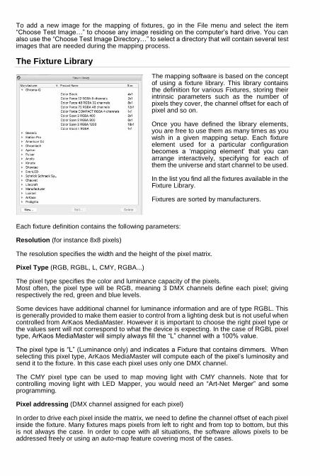
To add a new image for the mapping of fixtures, go in the File menu and select the item “Choose Test Image…” to choose any image residing on the computer’s hard drive. You can also use the “Choose Test Image Directory…” to select a directory that will contain several test images that are needed during the mapping process.
The Fixture Library
The mapping software is based on the concept of using a fixture library. This library contains the definition for various Fixtures, storing their intrinsic parameters such as the number of pixels they cover, the channel offset for each of pixel and so on. Once you have defined the library elements, you are free to use them as many times as you wish in a given mapping setup. Each fixture element used for a particular configuration becomes a ‘mapping element’ that you can arrange interactively, specifying for each of them the universe and start channel to be used. In the list you find all the fixtures available in the Fixture Library. Fixtures are sorted by manufacturers.
Each fixture definition contains the following parameters: Resolution (for instance 8x8 pixels) The resolution specifies the width and the height of the pixel matrix. Pixel Type (RGB, RGBL, L, CMY, RGBA...) The pixel type specifies the color and luminance capacity of the pixels. Most often, the pixel type will be RGB, meaning 3 DMX channels define each pixel; giving respectively the red, green and blue levels. Some devices have additional channel for luminance information and are of type RGBL. This is generally provided to make them easier to control from a lighting desk but is not useful when controlled from ArKaos MediaMaster. However it is important to choose the right pixel type or the values sent will not correspond to what the device is expecting. In the case of RGBL pixel type, ArKaos MediaMaster will simply always fill the “L” channel with a 100% value. The pixel type is “L” (Luminance only) and indicates a Fixture that contains dimmers. When selecting this pixel type, ArKaos MediaMaster will compute each of the pixel’s luminosity and send it to the fixture. In this case each pixel uses only one DMX channel. The CMY pixel type can be used to map moving light with CMY channels. Note that for controlling moving light with LED Mapper, you would need an “Art-Net Merger” and some programming. Pixel addressing (DMX channel assigned for each pixel) In order to drive each pixel inside the matrix, we need to define the channel offset of each pixel inside the fixture. Many fixtures maps pixels from left to right and from top to bottom, but this is not always the case. In order to cope with all situations, the software allows pixels to be addressed freely or using an auto-map feature covering most of the cases.

117
Creating or modifying a LED Fixture
To edit an existing fixture, select it in the fixture library list and press the “Edit” button at the bottom of the list. To create a new fixture, press the “New” button below the fixture list. In both cases it will open the LED Fixture dialog box:
This dialog allows you to define the manufacturer and product name of the fixture and choose its pixel type and resolution. Once those data have been defined, you need to press the “Apply Changes” button before you can patch the pixel addressing, either manually or using the auto-patch feature. The red squares indicate all pixels from the Fixture’s matrix. If they have a number in them, it represents their DMX addressing. The DMX addressing is the offset to be used to address that particular pixel. Pixels without numbers are not addressed, no pixel information will be sent to them Auto-patching gives a simple way to define an addressing that follows a row/column pattern. Simply specify the rule to fill out the matrix and click ‘Patch’. You will see the resulting addressing displayed inside the pixels. To patch pixel addresses manually, you need to click red squares one at a time in the correct order. Each time you click a pixel not yet patched, it will be given the next available DMX channel. You can always use the “Reset mapping” button to clear completely the mapping.
The Mapped Fixtures List
The “Mapped Fixtures List” contains all the mapped elements that have been already included into the current project. The address column provides the subnet, channel and universe used by the fixture.

Creating the LED mapping
When your set of fixtures is ready, you can start building a specific mapping, which can combine several fixtures into a mapping. To add a fixture, simply drag & drop it from the library onto the mapping area located on the right side of the screen. It will automatically create a ‘mapped fixture’ (an instance of a fixture in the mapping) and display the available parameters in the “Device Properties”, “DMX Mapping Properties” and “Mapping Properties” panes:
At this point, the LED Mapper will start sending DMX to the fixture. If your panels are properly connected, they should display the part of the image held inside the element’s area. If the panel doesn’t show any image, check the fixture definition, the DMX patching of the element as well as you hardware connections. The images sent for this particular element is also displayed in the “Preview” pane located under the mapping area.
Selecting the network interface and the sender application
The toolbar on the top of the mapping allows you to select the network interface where you want the Art-Net traffic to be sent:
If you want to create a mapping for a network not connected to your system you can select new and enter an address compatible with the system where the mapping will be used. If you are not sure of the complete IP address of the interface on that system you can by example simply use 2.x.x.x to allow selecting any interface that start by 2. Two LEDs are monitoring if packets are received or sent by the LED Mapper. Packets received by the LED Mapper are mainly Art-Net pool replies sent back by LED fixtures on the network. LED Mapper 3 supports any IP addresses including office network ranges like 192.168.x.x and more standard ranges 10.x.x.x and 2.x.x.x as defined by the protocol.

119
Before MediaMaster 5, the LED Mapper could not run simultaneously with MediaMaster because both would output to Art-Net. LED Mapper 3 has been enhanced to handle running side by side with MediaMaster. A sender selector toggles which application will output DMX to the fixtures:
This allows to quickly visualize the result of the mapping with the output of MediaMaster.
MediaMaster will immediately reload the mapping each time you save the file. When LED Mapper is the source of traffic, the LED in the Status panel of MediaMaster turns orange
Setting the Sender to LED Mapper means the LED Mapper should output Art-Net data instead of MediaMaster and in MediaMaster the LED will turn orange. When MediaMaster can send out Art-Net data, the LED turns blue again.
Editing the Device and DMX properties
The description in the device properties pane is a helper to identify your devices in the mapped fixtures list. The DMX properties give the address of the first DMX channel in the device. If IP address is set to “Auto” the LED Mapper will send the DMX channels to every device on the network. This makes the mapping easier to create, but can put a heavy load on every fixture in the network.
New in LED Mapper 3, you can set explicitly the IP address of a device. To assist you while setting the IP address, the IP menu is automatically populated with the fixtures nodes discovered on the network.
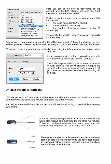
Here you see all the devices discovered on the network and the LED Mapper will send the DMX channels to the “dmXLAN node6” Each entry of the menu is the concatenation of this information: The node name (dmXLAN node6) The IP address (2.0.39.38) The number of devices assigned to that IP address (1) This avoids the need to enter IP addresses manually in most cases.
Only when you are creating a mapping file offline and you don’t have the devices on your network you need to enter the IP address manually and you must create a “Manual” IP address. When you create a manual address the dialog is using the information of the current active
network. If your main network is on 2.x.x.x you will only be able to enter the last 3 numbers of the IP address. The LED Mapper allows you to enter a manual network address. This allows creating a mapping file using IP addresses for devices, even if you are not yet connected to the network where the mapping will be used.
Unicast versus Broadcast
LED Mapper version 3 now supports the unicast transfer mode where packets of data can be sent directly to the addressed fixtures and not to the entire network. For backward compatibility, LED Mapper can still use broadcasting to send all data to every LED fixture.
In the Broadcast example here, each of the three fixtures would also receive data addressed to the other two fixtures. This would put three times more load on the network and the fixtures would be processing three times more data. The unicast transfer mode is more efficient because every packet of data is sent exclusively to the addressed fixture, as illustrated below. However unicast requires specifying the IP address of each fixture.
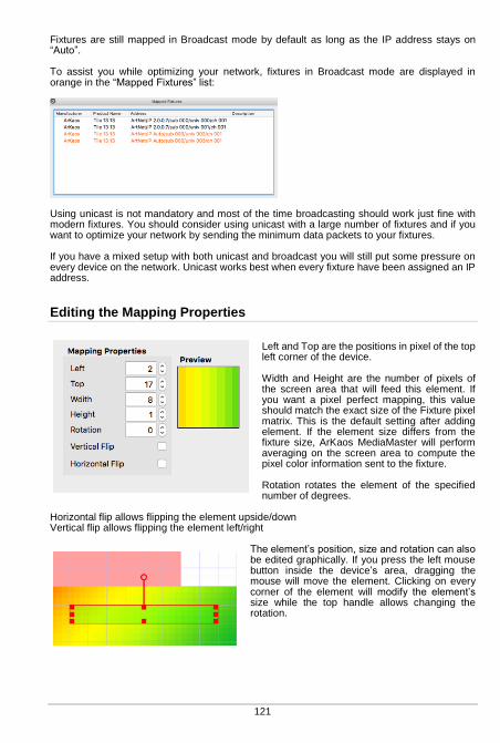
121
Fixtures are still mapped in Broadcast mode by default as long as the IP address stays on “Auto”. To assist you while optimizing your network, fixtures in Broadcast mode are displayed in orange in the “Mapped Fixtures” list:
Using unicast is not mandatory and most of the time broadcasting should work just fine with modern fixtures. You should consider using unicast with a large number of fixtures and if you want to optimize your network by sending the minimum data packets to your fixtures. If you have a mixed setup with both unicast and broadcast you will still put some pressure on every device on the network. Unicast works best when every fixture have been assigned an IP address.
Editing the Mapping Properties
Left and Top are the positions in pixel of the top left corner of the device. Width and Height are the number of pixels of the screen area that will feed this element. If you want a pixel perfect mapping, this value should match the exact size of the Fixture pixel matrix. This is the default setting after adding element. If the element size differs from the fixture size, ArKaos MediaMaster will perform averaging on the screen area to compute the pixel color information sent to the fixture. Rotation rotates the element of the specified number of degrees.
Horizontal flip allows flipping the element upside/down Vertical flip allows flipping the element left/right
The element’s position, size and rotation can also be edited graphically. If you press the left mouse button inside the device’s area, dragging the mouse will move the element. Clicking on every corner of the element will modify the element’s size while the top handle allows changing the rotation.
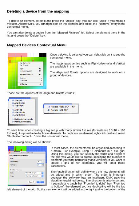
Deleting a device from the mapping
To delete an element, select it and press the “Delete” key, you can use “undo” if you made a mistake. Alternatively, you can right click on the element, and select the “Remove” entry in the contextual menu. You can also delete a device from the “Mapped Fixtures” list. Select the element there in the list and press the “Delete” key.
Mapped Devices Contextual Menu
Once a device is selected you can right click on it to see the contextual menu. The mapping properties such as Flip Horizontal and Vertical are available in the menu. The Align and Rotate options are designed to work on a group of devices.
Those are the options of the Align and Rotate entries:
To save time when creating a big setup with many similar fixtures (for instance 16x10 = 160 fixtures), it is possible to duplicate elements. To duplicate an element, right click on it and select “Duplicate Element…” from the contextual menu. The following dialog will be shown:
In most cases, the elements will be organized according to a matrix. For example, using 16 elements in a 4x4 grid. Using this dialog, you can specify the width and height of the grid you would like to create, specifying the number of elements you want horizontally and vertically. If you want to create a grid of 4x4 elements, you will enter these parameters. The Patch direction will define where the new elements will be added and in which order. The order is important because the software has an intelligent DMX patching algorithm explained below. The direction is also important: if you select to patch first “From left to right” then “From top to bottom”, the element you are duplicating will be the top
left element of the grid. So the new element will be added to the right and to the bottom of the
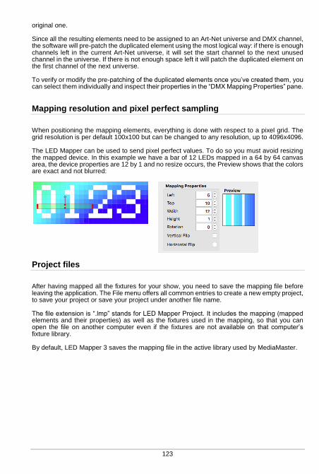
123
original one. Since all the resulting elements need to be assigned to an Art-Net universe and DMX channel, the software will pre-patch the duplicated element using the most logical way: if there is enough channels left in the current Art-Net universe, it will set the start channel to the next unused channel in the universe. If there is not enough space left it will patch the duplicated element on the first channel of the next universe. To verify or modify the pre-patching of the duplicated elements once you’ve created them, you can select them individually and inspect their properties in the “DMX Mapping Properties” pane.
Mapping resolution and pixel perfect sampling
When positioning the mapping elements, everything is done with respect to a pixel grid. The grid resolution is per default 100x100 but can be changed to any resolution, up to 4096x4096. The LED Mapper can be used to send pixel perfect values. To do so you must avoid resizing the mapped device. In this example we have a bar of 12 LEDs mapped in a 64 by 64 canvas area, the device properties are 12 by 1 and no resize occurs, the Preview shows that the colors are exact and not blurred:
Project files
After having mapped all the fixtures for your show, you need to save the mapping file before leaving the application. The File menu offers all common entries to create a new empty project, to save your project or save your project under another file name. The file extension is “.lmp” stands for LED Mapper Project. It includes the mapping (mapped elements and their properties) as well as the fixtures used in the mapping, so that you can open the file on another computer even if the fixtures are not available on that computer’s fixture library. By default, LED Mapper 3 saves the mapping file in the active library used by MediaMaster.
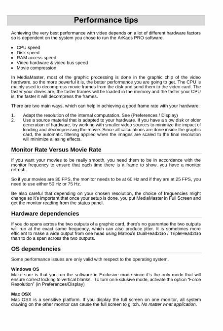
Performance tips
Achieving the very best performance with video depends on a lot of different hardware factors so is dependent on the system you chose to run the ArKaos PRO software. CPU speed Disk speed RAM access speed Video hardware & video bus speed Movie compression In MediaMaster, most of the graphic processing is done in the graphic chip of the video hardware, so the more powerful it is, the better performance you are going to get. The CPU is mainly used to decompress movie frames from the disk and send them to the video card. The faster your drives are, the faster frames will be loaded in the memory and the faster your CPU is, the faster it will decompress the frames. There are two main ways, which can help in achieving a good frame rate with your hardware: 1. Adapt the resolution of the internal computation. See (Preferences / Display) 2. Use a source material that is adapted to your hardware. If you have a slow disk or older
generation of hardware, try working with smaller video sources to minimize the impact of loading and decompressing the movie. Since all calculations are done inside the graphic card, the automatic filtering applied when the images are scaled to the final resolution will minimize aliasing effects.
Monitor Rate Versus Movie Rate
If you want your movies to be really smooth, you need them to be in accordance with the monitor frequency to ensure that each time there is a frame to show, you have a monitor refresh. So if your movies are 30 FPS, the monitor needs to be at 60 Hz and if they are at 25 FPS, you need to use either 50 Hz or 75 Hz. Be also careful that depending on your chosen resolution, the choice of frequencies might change so it’s important that once your setup is done, you put MediaMaster in Full Screen and get the monitor reading from the status panel.
Hardware dependencies
If you do spans across the two outputs of a graphic card, there’s no guarantee the two outputs will run at the exact same frequency, which can also produce jitter. It is sometimes more efficient to make a wide output from one head using Matrox’s DualHead2Go / TripleHead2Go than to do a span across the two outputs.
OS dependencies
Some performance issues are only valid with respect to the operating system.
Windows OS
Make sure is that you run the software in Exclusive mode since it’s the only mode that will ensure correct locking to vertical blanks. To turn on Exclusive mode, activate the option “Force Resolution” (in Preferences/Display)
Mac OSX
Mac OSX is a sensitive platform. If you display the full screen on one monitor, all system drawing on the other monitor can cause the full screen to glitch. No matter what application.
125
We have adapted the way the MediaMaster interface updates itself so that it won’t be interfering with the output but any other program updating its GUI will most likely be a problem. For this reason, in order to achieve the most fluid display under Mac OSX, we recommend to either quit or hide other visible window. For example, even the refresh of the clock in the menu bar can lead to one frame skipping.
Movie Compression
Besides size, the movie compression used has a huge impact both on the fluidity of the display and the movie playability. The software is using internally FFMPEG to decode most codecs and doesn’t need to use QuickTime or another decoder, which takes up more hardware resources to complete. MPEG-2 is the compression codec that we have found to give the best performances in most configurations, if playing the movie forward at a reasonable speed.
Note:
The more complex or heavier the compression used, the more work the processor will have to do to decompress the video for playback and this can result in reduced performance.
In addition to the compression method itself, there’s the issue of key frames. Most widely spread compression mechanism work using incremental methods, which means they construct a frame by storing the difference between a frame and the previous one (temporal compression). In order to keep the process from deriving too much from the original material, they store an original frame every now and then, and start again coding incremental information from that frame on. These original frames are called ‘key frames’. Using sparse key frames will mean that for MediaMaster to access a given frame, it will have to find the previous key frame and process all the intermediate frame differences until it reaches the desired one. This is not a problem until you play your movie with special loop modes (such as ping-pong) or when increasing playback speed (changing movie speed channel). The bitrate of the movie will define how much data is stored per second of video. Increasing the bitrate increases quality, and necessary hard disk bandwidth and CPU load for decompression. The bitrate must be high depending on the movie resolution. For instance for a full HD movie (1080p = 1920x1080), the recommended bitrate is between 15 Mbps and 40 Mbps (Mega bit per second). To play multiple movies in high resolution at the same time, it is recommended to use a multi-core CPU and multiple hard drives in a RAID array. If you are not satisfied with MPEG-2 quality, or if you need to play your movies with various playback modes (backward etc.) it is recommended to use a movie without temporal compression. The most adapted for MediaMaster is the QuickTime PhotoJPEG codec. It will be handled directly by the application without using QuickTime (through the internal FFMPEG player). Setting the quality between 60% and 80% is generally enough.
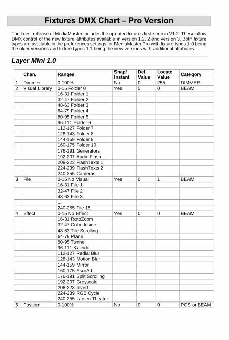
Fixtures DMX Chart – Pro Version
The latest release of MediaMaster includes the updated fixtures first seen in V1.2. These allow DMX control of the new fixture attributes available in version 1.2, 2 and version 3. Both fixture types are available in the preferences settings for MediaMaster Pro with fixture types 1.0 being the older versions and fixture types 1.1 being the new versions with additional attributes.
Layer Mini 1.0
Chan. Ranges Snap/ Instant
Def. Value
Locate Value
Category
1 Dimmer 0-100% No 0 255 DIMMER
2 Visual Library 0-15 Folder 0 Yes 0 0 BEAM
16-31 Folder 1
32-47 Folder 2
48-63 Folder 3
64-79 Folder 4
80-95 Folder 5
96-111 Folder 6
112-127 Folder 7
128-143 Folder 8
144-159 Folder 9
160-175 Folder 10
176-191 Generators
192-207 Audio Flash
208-223 FlashTexts 1
224-239 FlashTexts 2
240-255 Cameras
3 File 0-15 No Visual Yes 0 1 BEAM
16-31 File 1
32-47 File 2
48-63 File 3
...
240-255 File 15
4 Effect 0-15 No Effect Yes 0 0 BEAM
16-31 RotoZoom
32-47 Cube Inside
48-63 Tile Scrolling
64-79 Plane
80-95 Tunnel
96-111 Kaleido
112-127 Radial Blur
128-143 Motion Blur
144-159 Mirror
160-175 AsciiArt
176-191 Split Scrolling
192-207 Greyscale
208-223 Invert
224-239 RGB Cycle
240-255 Larsen Theater
5 Position 0-100% No 0 0 POS or BEAM

127
Layer Tiny 1.0
Chan. Ranges Snap/ Instant
Def. Value Locate Value
Category
1 Dimmer 0-100% No 0 255 DIMMER
2 Visual Library 0 User Folder 0 Yes 0 0 BEAM
1 User Folder 1
...
239 User Folder 239
240 Generators
242 Audio Flahs
250 FlashTexts 1
251 FlashTexts 2
252 FlashTexts 3
253 FlashTexts 4
254 Cameras
255 Masks
3 File 0 Prev. Layer Yes 0 1 BEAM
1-255 File 1-255
4 Effect Library 0-15 3D Yes 0 0 BEAM
16-31 Color
32-47 Blur
48-63 Split
64-79 Artistic
5 Effect 0 No Effect Yes 0 0 BEAM
1-255 Effect 1-255
6 Effect Parameter 0-100% No 128 128 BEAM
7 Red level 0-100% No 255 255 COLOR
8 Green level 0-100% No 255 255 COLOR
9 Blue level 0-100% No 255 255 COLOR
10 ScaleX - coarse 0-100% No 255-255 255-255 POS
11 ScaleX - fine
12 ScaleY - coarse 0-100% No 255-255 255-255 POS
13 ScaleY - fine
14 Pan/PositionX - coarse
0-100% No 128-128 128-128 POS
15 Pan/PositionX - fine
16 Tilt/PositionY - coarse
0-100% No 128-128 128-128 POS
17 Tilt/PositionY - fine
18 PositionZ - coarse 0-100% No 128-128 128-128 POS
19 PositionZ - fine
20 Text 0-255 Text 0-255 Yes 0 0 BEAM
Layer Full 1.1
Chan. Ranges Snap/ Instant
Def. Value
Locate Value
Category
1 Dimmer 0-100% No 0 255 DIMMER
2 Visual Library 0 User Folder 0 Yes 0 0 BEAM
1 User Folder 1
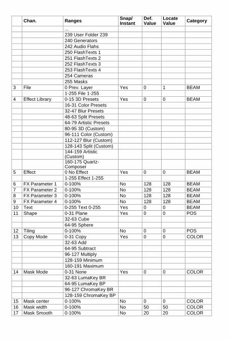
Chan. Ranges Snap/ Instant
Def. Value
Locate Value
Category
...
239 User Folder 239
240 Generators
242 Audio Flahs
250 FlashTexts 1
251 FlashTexts 2
252 FlashTexts 3
253 FlashTexts 4
254 Cameras
255 Masks
3 File 0 Prev. Layer Yes 0 1 BEAM
1-255 File 1-255
4 Effect Library 0-15 3D Presets Yes 0 0 BEAM
16-31 Color Presets
32-47 Blur Presets
48-63 Split Presets
64-79 Artistic Presets
80-95 3D (Custom)
96-111 Color (Custom)
112-127 Blur (Custom)
128-143 Split (Custom)
144-159 Artistic (Custom)
160-175 Quartz-Composer
5 Effect 0 No Effect Yes 0 0 BEAM
1-255 Effect 1-255
6 FX Parameter 1 0-100% No 128 128 BEAM
7 FX Parameter 2 0-100% No 128 128 BEAM
8 FX Parameter 3 0-100% No 128 128 BEAM
9 FX Parameter 4 0-100% No 128 128 BEAM
10 Text 0-255 Text 0-255 Yes 0 0 BEAM
11 Shape 0-31 Plane Yes 0 0 POS
32-63 Cube
64-95 Sphere
12 Tiling 0-100% No 0 0 POS
13 Copy Mode 0-31 Copy Yes 0 0 COLOR
32-63 Add
64-95 Subtract
96-127 Multiply
128-159 Minimum
160-191 Maximum
14 Mask Mode 0-31 None Yes 0 0 COLOR
32-63 LumaKey BR
64-95 LumaKey BP
96-127 ChromaKey BR
128-159 ChromaKey BP
15 Mask center 0-100% No 0 0 COLOR
16 Mask width 0-100% No 50 50 COLOR
17 Mask Smooth 0-100% No 20 20 COLOR
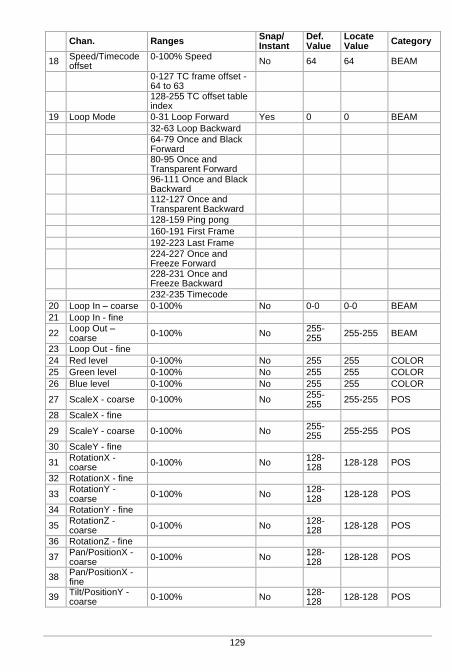
129
Chan. Ranges Snap/ Instant
Def. Value
Locate Value
Category
18 Speed/Timecode offset
0-100% Speed
No 64 64 BEAM
0-127 TC frame offset -64 to 63
128-255 TC offset table index
19 Loop Mode 0-31 Loop Forward Yes 0 0 BEAM
32-63 Loop Backward
64-79 Once and Black Forward
80-95 Once and Transparent Forward
96-111 Once and Black Backward
112-127 Once and Transparent Backward
128-159 Ping pong
160-191 First Frame
192-223 Last Frame
224-227 Once and Freeze Forward
228-231 Once and Freeze Backward
232-235 Timecode
20 Loop In – coarse 0-100% No 0-0 0-0 BEAM
21 Loop In - fine
22 Loop Out – coarse
0-100% No 255-255
255-255 BEAM
23 Loop Out - fine
24 Red level 0-100% No 255 255 COLOR
25 Green level 0-100% No 255 255 COLOR
26 Blue level 0-100% No 255 255 COLOR
27 ScaleX - coarse 0-100% No 255-255
255-255 POS
28 ScaleX - fine
29 ScaleY - coarse 0-100% No 255-255
255-255 POS
30 ScaleY - fine
31 RotationX - coarse
0-100% No 128-128
128-128 POS
32 RotationX - fine
33 RotationY - coarse
0-100% No 128-128
128-128 POS
34 RotationY - fine
35 RotationZ - coarse
0-100% No 128-128
128-128 POS
36 RotationZ - fine
37 Pan/PositionX - coarse
0-100% No 128-128
128-128 POS
38 Pan/PositionX - fine
39 Tilt/PositionY - coarse
0-100% No 128-128
128-128 POS
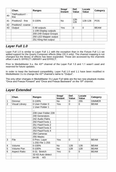
Chan. Ranges Snap/ Instant
Def. Value
Locate Value
Category
40 Tilt/PositionY - fine
41 PositionZ - fine 0-100% No 128-128
128-128 POS
42 PositionZ -coarse
43 Output 0 All outputs Yes 0 0 BEAM
1-199 Display outputs
200-249 Output Groups
250 LED Mapper output
251 Kling-Net output
Layer Full 1.0
Layer Full 1.0 is similar to Layer Full 1.1 with the exception than in the Fixture Full 1.1 we added support for the Quartz Composer effects (Mac OS X only). The channel mapping is not changed but the library of effects has been expanded. Those are accessed by the channels offset 4 and 5: EFFECT LIBRARY and EFFECT. Prior to MediaMaster 3.x, the 43rd channel of the Layer Full 1.0 and 1.1 wasn’t used and reserved for future updates. In order to keep the backward compatibility, Layer Full 1.0 and 1.1 have been modified in MediaMaster 3.x to change the 43rd channel’s name to “Output”. The only other changes in MediaMaster 3‘s Layer Full table are the two new playback modes “Once and Freeze Forward” and “Once and Freeze Backward” on the 19th channel.
Layer Extended
Chan. Ranges Snap/ Instant
Def. Value
Locate Value
Category
1 Dimmer 0-100% No 0 255 DIMMER
2 Visual Library 0 User Folder 0 Yes 0 0 BEAM
1 User Folder 1
...
239 User Folder 239
240 Generators
242 Audio Flahs
250 FlashTexts 1
251 FlashTexts 2
252 FlashTexts 3
253 FlashTexts 4
254 Cameras
255 Masks
3 File 0 Prev. Layer Yes 0 1 BEAM
1-255 File 1-255
4 Volume 0-100% No 128 128 BEAM
5 Volume Pan 0-100% No 128 128 BEAM
6 Aspect Ratio 0-31 Stretch Yes 0 0 BEAM
32-63 Auto detect
64-95 4/3
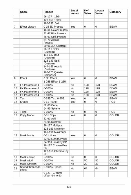
131
Chan. Ranges Snap/ Instant
Def. Value
Locate Value
Category
96-127 16/9
128-159 16/10
160-191 5/4
7 Effect Library 0-15 3D Presets Yes 0 0 BEAM
16-31 Color Presets
32-47 Blur Presets
48-63 Split Presets
64-79 Artistic Presets
80-95 3D (Custom)
96-111 Color (Custom)
112-127 Blur (Custom)
128-143 Split (Custom)
144-159 Artistic (Custom)
160-175 Quartz-Composer
8 Effect 0 No Effect Yes 0 0 BEAM
1-255 Effect 1-255
9 FX Parameter 1 0-100% No 128 128 BEAM
10 FX Parameter 2 0-100% No 128 128 BEAM
11 FX Parameter 3 0-100% No 128 128 BEAM
12 FX Parameter 4 0-100% No 128 128 BEAM
13 Text 0-255 Text 0-255 Yes 0 0 BEAM
14 Shape 0-31 Plane Yes 0 0 POS
32-63 Cube
64-95 Sphere
15 Tiling 0-100% No 0 0 POS
16 Copy Mode 0-31 Copy Yes 0 0 COLOR
32-63 Add
64-95 Subtract
96-127 Multiply
128-159 Minimum
160-191 Maximum
17 Mask Mode 0-31 None Yes 0 0 COLOR
32-63 LumaKey BR
64-95 LumaKey BP
96-127 ChromaKey BR
128-159 ChromaKey BP
18 Mask center 0-100% No 0 0 COLOR
19 Mask width 0-100% No 50 50 COLOR
20 Mask Smooth 0-100% No 20 20 COLOR
21 Speed/Timecode offset
0-100% Speed
No 64 64 BEAM
0-127 TC frame offset -64 to 63
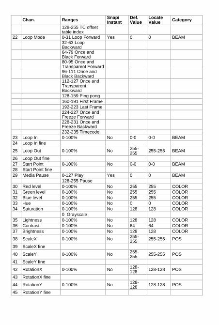
Chan. Ranges Snap/ Instant
Def. Value
Locate Value
Category
128-255 TC offset table index
22 Loop Mode 0-31 Loop Forward Yes 0 0 BEAM
32-63 Loop Backward
64-79 Once and Black Forward
80-95 Once and Transparent Forward
96-111 Once and Black Backward
112-127 Once and Transparent Backward
128-159 Ping pong
160-191 First Frame
192-223 Last Frame
224-227 Once and Freeze Forward
228-231 Once and Freeze Backward
232-235 Timecode
23 Loop In 0-100% No 0-0 0-0 BEAM
24 Loop In fine
25 Loop Out 0-100% No 255-255
255-255 BEAM
26 Loop Out fine
27 Start Point 0-100% No 0-0 0-0 BEAM
28 Start Point fine
29 Media Pause 0-127 Play Yes 0 0 BEAM
128-255 Pause
30 Red level 0-100% No 255 255 COLOR
31 Green level 0-100% No 255 255 COLOR
32 Blue level 0-100% No 255 255 COLOR
33 Hue 0-100% No 0 0 COLOR
34 Saturation 0-100% No 128 128 COLOR
0 Grayscale
35 Lightness 0-100% No 128 128 COLOR
36 Contrast 0-100% No 64 64 COLOR
37 Brightness 0-100% No 128 128 COLOR
38 ScaleX 0-100% No 255-255
255-255 POS
39 ScaleX fine
40 ScaleY 0-100% No 255-255
255-255 POS
41 ScaleY fine
42 RotationX 0-100% No 128-128
128-128 POS
43 RotationX fine
44 RotationY 0-100% No 128-128
128-128 POS
45 RotationY fine
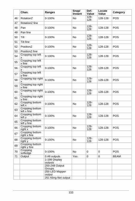
133
Chan. Ranges Snap/ Instant
Def. Value
Locate Value
Category
46 RotationZ 0-100% No 128-128
128-128 POS
47 RotationZ fine
48 Pan 0-100% No 128-128
128-128 POS
49 Pan fine
50 Tilt 0-100% No 128-128
128-128 POS
51 Tilt fine
52 PositionZ 0-100% No 128-128
128-128 POS
53 PositionZ fine
54 Cropping top left x
0-100% No 128-128
128-128 POS
55 Cropping top left x fine
56 Cropping top left y
0-100% No 128-128
128-128 POS
57 Cropping top left y fine
58 Cropping top right x
0-100% No 128-128
128-128 POS
59 Cropping top right x fine
60 Cropping top right y
0-100% No 128-128
128-128 POS
61 Cropping top right y fine
62 Cropping bottom left x
0-100% No 128-128
128-128 POS
63 Cropping bottom left x fine
64 Cropping bottom left y
0-100% No 128-128
128-128 POS
65 Cropping bottom left y fine
66 Cropping bottom right x
0-100% No 128-128
128-128 POS
67 Cropping bottom right x fine
68 Cropping bottom right y
0-100% No 128-128
128-128 POS
69 Cropping bottom right y fine
70 Cropping softedge
0-100% No 0 0 POS
71 Output 0 All outputs Yes 0 0 BEAM
1-199 Display outputs
200-249 Output Groups
250 LED Mapper output
251 Kling-Net output
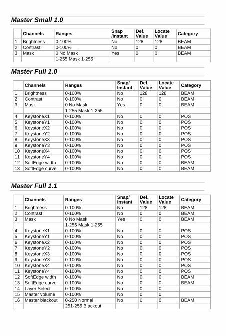
Master Small 1.0
Channels Ranges Snap /Instant
Def. Value
Locate Value
Category
1 Brightness 0-100% No 128 128 BEAM
2 Contrast 0-100% No 0 0 BEAM
3 Mask 0 No Mask Yes 0 0 BEAM
1-255 Mask 1-255
Master Full 1.0
Channels Ranges Snap/ Instant
Def. Value
Locate Value
Category
1 Brightness 0-100% No 128 128 BEAM
2 Contrast 0-100% No 0 0 BEAM
3 Mask 0 No Mask Yes 0 0 BEAM
1-255 Mask 1-255
4 KeystoneX1 0-100% No 0 0 POS
5 KeystoneY1 0-100% No 0 0 POS
6 KeystoneX2 0-100% No 0 0 POS
7 KeystoneY2 0-100% No 0 0 POS
8 KeystoneX3 0-100% No 0 0 POS
9 KeystoneY3 0-100% No 0 0 POS
10 KeystoneX4 0-100% No 0 0 POS
11 KeystoneY4 0-100% No 0 0 POS
12 SoftEdge width 0-100% No 0 0 BEAM
13 SoftEdge curve 0-100% No 0 0 BEAM
Master Full 1.1
Channels Ranges Snap/ Instant
Def. Value
Locate Value
Category
1 Brightness 0-100% No 128 128 BEAM
2 Contrast 0-100% No 0 0 BEAM
3 Mask 0 No Mask Yes 0 0 BEAM
1-255 Mask 1-255
4 KeystoneX1 0-100% No 0 0 POS
5 KeystoneY1 0-100% No 0 0 POS
6 KeystoneX2 0-100% No 0 0 POS
7 KeystoneY2 0-100% No 0 0 POS
8 KeystoneX3 0-100% No 0 0 POS
9 KeystoneY3 0-100% No 0 0 POS
10 KeystoneX4 0-100% No 0 0 POS
11 KeystoneY4 0-100% No 0 0 POS
12 SoftEdge width 0-100% No 0 0 BEAM
13 SoftEdge curve 0-100% No 0 0 BEAM
14 Layer Select 0-100% No 0 0
15 Master volume 0-100% No 0 0
16 Master blackout 0-250 Normal No 0 0 BEAM
251-255 Blackout
135
Terminology / Glossary of Terms
ArtNet – An open source data protocol, now often recognized as an industry standard, for the broadcast of DMX data over a standard Ethernet network.
DMX – A digital multiplexed data stream used for control of lighting and video devices. Fixture – For operation of the software from a lighting console the multiple attributes for
each layer as well as global commands are arranged into a fixture profile – in exactly the same way as if you where to control an automated lighting instrument from a console where you would have multiple parameters for each light – such as pan, tilt, color, intensity etc.
Keystoning – The process of Keystoning allows you to digitally alter the proportions of the
image in order to help fit the output to the screen. Layer – This describes one complete element of video composition including media, effects
and parameter definition. These layers of video are blended or mixed together to created the final output.
LTP – This stands for Last Takes Precedence and is a lighting term used to describe how
data is managed where the last value of data sent – be it lower or higher than the previous data – is regarded as having priority.
MA-Net – This is the data protocol proprietary to GrandMA that allows fast communication
between all Ma-Net compatible devices. Mask – A 2D image of which certain sections are transparent which is used over the top of
other video data to hide or mask out certain areas of the output image. The digital equivalent of putting a piece of black card with a shape cut out of it in front of your TV.
MSEX – MSEX stands for Media Server Extension and is a protocol that runs on top of
DMX over Ethernet allowing for bi-directional communication between the media server and console.
Display – A Display is a device that’s connected to the computer graphical card using DVI,
HDMI, DisplayPort or VGA connectors. A computer monitor, a television screen, a video projector are different kind of displays.
Output – An output is the destination of the video content coming from a combination of
layers. The Full screen Display in Instant mode, Kling-Net, the LED Mapper or all the Video Mapper Surfaces are different outputs – It’s possible to create groups of outputs using the dedicated Output management dialog.
Surface – A Surface is a shape that’s created on a specific Display using the Video Mapper
application. Each Surface is a separated output in MediaMaster.
Parameter – A specific function of the software which has a fixed range and the setting of which will affect the output. For example the playback speed of a piece of video is a parameter.
Patch (Theater Mode interface Only) – A collection Visual presets (see below) contained
within a master group number. The Theater Mode has 64 patches. Quartz Composer – Quartz Composer is a node-based visual programming language
provided as part of Mac OS X for processing and rendering graphical data. Surface: Deformable shape attached to a display, created in the Video Mapper. Each
surface is considered as a separate output by MediaMaster, meaning that each can

display a different set of visuals. Virtual Encoder – The same as a rotary dial on a physical console, a virtual
encoder allows you to change the setting of a specific parameter. To use the virtual encoders click and hold on the encoder graphic and then move the mouse up or down the screen to increase or decrease the encoder value: this is shown with a series of white bars around the encoder.
Visual – In ArKaos PRO a visual refers to a video, an image, a text display or input from a
camera or acquisition board Visual Preset (Theater Mode interface Only) – Similar to a submaster or cue on a lighting
console a visual preset in the Theater Mode is a pre-selected media clip along with specific parameter settings including effects, position and mixing type which can be directly recalled by DMX, MIDI or Keyboard using a single fader, note or button press. There are 64 visual presets per patch and thus 4096 visual presets per media library in Theater Mode interface.

137
Support, Information and Contact
ArKaos PRO has created a number of support channels for users to ensure you get the most direct and efficient answers to any questions or support requests you may have.
ArKaos PRO Support Centre : http://support.ArKaos.net/
ArKaos PRO Users Forum : http://www.ArKaos.net/forum
Solutions
As always, our support team is ready to help you if you should encounter any problem upgrading to the new version.
ArKaos PRO Users Forum
If you just want to discuss with other ArKaos PRO software users, share tips and experiences about our products or third party software / hardware etc. Our Users Forum is the place to be! (This is not the place to request for help, see below).
Knowledgebase articles
Our online Support Centre features a FAQ / Knowledgebase where a solution to the most common registration / configuration problems has been posted.
Trouble Ticket System
Our online Support Centre also features a Trouble Ticket System, which allows our team to receive your support requests and follow up the resolution of your problem as well as eventual future issues. We strongly recommend that you register for an ArKaos PRO Support Account (free) on our Support Centre in order to be able to check the status of your trouble tickets, post replies to our team or create new trouble tickets directly from our web interface. Our support team answers your requests during office hours (CET) on weekdays.
Distributors and resellers
Our distributors and resellers are also at your service if you would like to request information in your language, advice on additional hardware or software, solutions or quotes for a particular configuration etc. A complete list of distributors and resellers for VJ/DJ or Show/lighting products can be found on our web site at: http://www.arkaospro.com/dealers
Thank you very much for your interest in our products, we hope you will enjoy using this version as much as we enjoyed creating it! The ArKaos PRO Team

www.arkaospro.com
D O C U M E N T A T I O N


