ARMY TM 11-5815-602-10 NAVY EE161-DM-OPI-010/E154UGC74 AIR FORCE TO 31W4-2UGC74-1 OPERATOR’S MANUAL EQUIPMENT DESCRIPTION Page 1-5 OPERATING INSTRUCTIONS Page 2-0 DESCRIPTION OF CONTROLS Page 2-1 PREVENTIVE MAINTENANCE CHECKS AND SERVICES (PMCS) Page 2-39 OPERATOR MAINTENANCE INSTRUCTIONS Page 3-1 TROUBLESHOOTING Page 3-3 TERMINAL, COMMUNICATIONS AN/UGC-74A(V)3 (NSN 5815-01-062-8194) SUBJECT INDEX Page Index-1 DEPARTMENTS OF THE ARMY, THE NAVY, AND THE AIR FORCE 23 SEPTEMBER 1983
Transcript
A R M Y T M 1 1 - 5 8 1 5 - 6 0 2 - 1 0N A V Y E E 1 6 1 - D M - O P I - 0 1 0 / E 1 5 4 U G C 7 4
D E P A R T M E N T S O F T H E A R M Y , T H E N A V Y , A N D T H E A I R F O R C E
2 3 S E P T E M B E R 1 9 8 3
may
HIGH VOLTAGE
is used in the operation of this equipment
DEATH ON CONTACT
result if personnel fail to observe safety precautions
Never work on electronic equipment unless there is another person nearby who is familiar with theoperation and hazards of the equipment and who is competent in administering first aid. When thetechnician is aided by operators, he must warn them about dangerous areas.
Whenever possible, the power supply to the equipment must be shut off before beginning work onthe equipment. Take particular care to ground every capacitor likely to hold a dangerous potential.When working inside the equipment, after the power has been turned off, always ground every partbefore touching it.
Be careful not to contact high voltage input connections of 115/230 volt ac when installing oroperating this equipment.
Whenever the nature of the operation permits, keep one hand away from the equipment to reducethe hazard of current flowing through vital organs of the body.
For Artificial
Do not be misled by the term “low voltage”.may cause death under adverse conditions.
Respiration, refer to FM 21-11.
Potentials as low as 50 volts
TM 11-5815-602-10EE161-DM-OPI-010/E154UGC74
TO 31W4-2UGC74-1
Adequate ventilation should be provided while using TRICHLOROTRIFLUOROETHANE. Prolongedbreathing of vapor should be avoided. The solvent should not be used near heat or open flame; theproducts of decomposition are toxic and irritating. Since TRICHLOROTRIFLUOROETHANE dissolvesnatural oils, prolonged contact with skin should be avoided. When necessary use gloves which thesolvent cannot penetrate. If the solvent is taken internally, consult a physician immediately.
Lithium organic batteries or cells are used in this equipment. They are potentially hazardous ifmisused or tampered with before, during, or after discharge. The following precautions must bestrictly observed to prevent possible injury to personnel or equipment damage:
DO NOT heat, incinerate, crush, puncture, disassemble, or otherwisemutilate the batteries.
DO NOT short circuit, recharge, or bypass internal fuse.
DO NOT store in equipment during long period of nonuse in excess of 30days.
TURN OFF the equipment immediately if you detect battery compart-ment becoming unduly hot, hear battery cells venting (hissing sound), orsmell irritating sulphur dioxide gas. Remove and dispose of the batteryonly after it is cool (30-60 minutes).
SAFETY STEPS TO FOLLOW IF SOMEONEIS THE VICTIM OF ELECTRICAL SHOCK
DO NOT TRY TO PULL OR GRAB THE INDIVIDUAL
IF POSSIBLE , TURN OFF THE ELECTRICAL POWER
IF YOU CANNOT TURN OFF THE ELECTRICALPOWER, PULL, PUSH, OR LIFT THE PERSON TOSAFETY USING A WOODEN POLE OR A ROPE ORSOME OTHER INSULATING MATERIAL
SEND FOR HELP AS SOON AS POSSIBLE
AFTER THE INJURED PERSON IS FREE OFCONTACT WITH THE SOURCE OF ELECTRICALSHOCK, MOVE THE PERSON A SHORT DISTANCEAWAY AND IMMEDIATELY START ARTIFICIALRESUSCITATION
B
TM 11-5815-602-10EE161-DM-OPI-010/E154UGC74
TO 31W4-2UGC74-1
TECHNICAL MANUALNo. 11-5815-602-10
DEPARTMENTS OF THE ARMY, THE NAVY,
No. EE161-DM-OPl-010/E154UGC74 AND THE AIR FORCETECHNICAL ORDERNo. 31W4-2UGC74-1 WASHINGTON, DC, 23 September 1983
You can help improve this manual. If you find any mistakes or if youknow of a way to improve the procedures, please let us know. Mail yourletter, DA Form 2028 (Recommended Changes to Publications and BlankForms), or DA Form 2028-2 located in back of this manual direct to:Commander, US Army Communications-Electronics Command and FortMonmouth, ATTN: DRSEL-ME-MP, Fort Monmouth, New Jersey 07703.
For Air Force, submit AFTO Form 22 (Technical Order System Publica-tion Improvement Report and Reply) in accordance with paragraph 6-5,Section VI, T.O. 00-5-1. Forward direct to prime ALC/MST.
For Navy, mail comments to the Commander, Naval ElectronicsSystems Command, ATTN: ELEX 8122, Washington, DC 20360.
In either case, a reply will be furnished direct to you.
T A B L E O F C O N T E N T S
HOW TO USE THIS MANUAL . . . . . . . . . . . . . . . . . . . . . . . . . . . . . . . . . .
This manual tells you how to operate and perform operator maintenance on the Communica-tions Terminal AN/UGC-74A(V)3.
Location of Subjects in Manual
In this manual, paragraphs and pages are numbered in succession by chapter. For example:Paragraph 2-14 is paragraph 14 in Chapter 2. Page 3-5 is page 5 in Chapter 3.
If you are looking for specific information use subject INDEX in the back of this manual tolocate page number where the topic is described.
For rapid location of a required subject, contents of chapter are listed alphabetically on thefirst page of each chapter.
Refer to Appendix A, REFERENCES, for the complete title of all forms, technical manualsmilitary specifications referenced in this manual.
Refer to LIST OF ABBREVIATIONS and GLOSSARY in Chapter 1 for a definition of the ab-breviations and unusual terms used
Use of Manual for Task Performance
in this manual.
and
You must become thoroughly familiar with all the operating controls, switches, lamps and keysbefore you can properly use and maintain the terminal. Chapter 2 describes the use of operatorcontrols, while Chapter 3 tells you how to maintain the equipment.
As a further aid to knowing operating procedures, Appendixes E through J, located in the backof the manual, provide information and detailed examples of operator action and terminalresponse in the operational states.
Use this manual in conjunction with your station’s Standard Operating Procedure (SOP) whenformatting messages. Appendix H provides an example of a JANAP 128(H) PLAIN DRESS headerand message.
You must familiarize yourself with all the maintenance procedures before beginning themaintenance task.
Do not perform maintenance tasks that are assigned to a maintenance level higher than youare authorized to perform. Call your supervisor or next higher level of maintenance if you have aproblem not described in this manual.
b. Report of Packaging and Handling Deficiencies. Fill out and forward SF 364 (Report of
Discrepancy (ROD)) as prescribed in AR 735-11-2/DLAR 4140.55/NAVMATlNST 4355.73A/AFR400-54/MCO 4430.3F.
c. Discrepancy in Shipment Report (DISREP) (SF 361). Fill out and forward Discrepancy in Shipment
Report (DISREP) (SF 361) as prescribed in AR 55-38/NAVSUPlNST 4610.33C/AFR 75-18/MCO
P4610.19D/DLAR 4500.15.
1-3. HAND RECEIPT (-HR) MANUAL
This manual has a companion document with a TM number followed by “-HR” (whichstands for Hand Receipt). TM 11-5815-602-10-HR consists of preprinted hand receipts (DAForm 2062) that list end item related equipment (i.e., COEI, Bll, AND AAL) you must accountfor. As an aid to property accountability, additional -HR manuals may be requisitioned fromThe US Army Adjutant General Publications Center, Baltimore, MD, in accordance with theprocedures In Chapter 3, AR 310-2, and DA PAM 310-10-2.
a. Army. If your Terminal, Communications AN/UGC-74A(V)3 needs improvements, let usknow. Send us an EIR. You, the user, are the only one who can tell us what you don’t likeabout your equipment. Let us know why you don’t like the design. Put it on an SF 368(Quality Deficiency Report). Mail it to Commander, US Army Communication- ElectronicsCommand and Fort Monmouth, ATTN: DRSEL-ME-MP, Fort Monmouth, New Jersey 07703.We’ll send you a reply.
b. Air Force. Air Force personnel are encouraged to submit ElR’s in accordance with AFR900-4.
c. Navy. Navy personnel are encouraged to submit ElR’s through their local BeneficialSuggestion Program.
1-5. NOMENCLATURE CROSS-REFERENCE LIST
Common names will be used when the major components of the terminal are mentionedin this manual.
American Standard Code for lnformation InterchangeBatteryBell CodeBrightBackspaceCentral Processing UnitCarriage ReturnControlDeleteDelete Last CharacterDelete Last LineElectro Magnetic InductionElasped Time MetersHaltIntelligent Communications TerminalInternal/ExternalKeyboard Send/ReceiveLine-FeedLockMaximumMessage ReceivedModification Work OrdersNon-Return to ZeroRecordReviewRadio Frequency InterferenceReceive OnlyStandard Operating ProcedureTransmit
TM 11-5815-602-10EE161-DM-OPI-010/E154UGC74
TO 31W4-2UGC74-1
1-7. GLOSSARY
ASCII . . . . . . . . . . . . . . . . . . An abbreviation for, American Standard Code for Information inter-change. A seven-bit plus parity code developed by the AmericanStandards Association. (Refer to Appendix E for complete descrip-tion of ASCII).
Baud Code FIG-LTRS . . . . . A 5-level code used for telegraph keyboard printers, punches andreaders. Five bits can accept only 32 special codes, of which twoare figures (FIGS) and letters (LTRS). Placing the FIGS or LTRS codebefore other bit combinations permits dual definition of the remain-ing codes. So when a Baudot terminal is interfaced to a computer,the software must maintain proper FIGS-LTRS status in order tointerpret the necessary data properly.
Baud Rate . . . . . . . . . . . . . . In data communications, a fixed amount of time is devoted to sen-ding a pulse, known as a binary digit or “bit”.A bit can be either apositive pulse, as a telegraph dot, or a blank, as a telegraph pause.The number of bits that can be transmitted in one second is thebaud rate.
Buffer . . . . . . . . . . . . . . . . . . A storage device used to compensate for difference in the rate offlow of information or the time of occurence of events.
Delimiter . . . . . . . . . . . . . . . Any ASCII character used as a space or separator. It cannot appearin the same string for which it is a delimiter.
Envelope . . . . . . . . . . . . . . . A group of binary digits, including data and call control signals,which is transmitted or received as a complete unit. The data, allcontrol signals, and possibly error control information, are arrangedin a specific format.
Hexadecimal Code . . . . . . . Two digits (2 numbers or a number and a letter) representing theASCII code for a character. (See Appendix G, table G-1, “HEX-ASCII”Conversion.) Hexadecimal digits are used in the End-of-line subcom-mand in a sequence in place of a carriage-return, and in theTenvelope and Renvelope subcommands start and stop sequences.System abbreviation for hexadecimal digits is HH.
Interface . . . . . . . . . . . . . . . . A method used to interconnect two equipments or systems. Themethod includes the type, quality and function of the interconnec-ting circuits and the type and form of signals to be interchangedthrough these circuits.
To space a typewritten line so that it is exactly the intendedlength.
Position within the message file always points to the first characterof the current line.
To remember, helping, or meant to help the memory.
A mode of recording in which each state of the medium cor-responds to one binary state. In this mode, the state of the recor-ding medium changes when the information changes from 1 to 0 orfrom 0 to 1.
NOTE“NRZ modified” is also often
A binary digit attached to an array of bitsbits either always odd or always even.
called “NRZ”.
to make the sum of all the
Addition of non-information bits to data, making the number of onesin a grouping of bits either always even or always odd. This permitsdetection of bit groupings which contain single errors. It may be ap-plied to characters, blocks, or any convenient bit grouping.
Allows the operator to set the envelope which is put around amessage for reception by the system. This sequence never appearsin the message storage and is used for communications purposesonly.
Allows the operator to set the envelope which is put around amessage for transmission by the system. This sequence never ap-pears in the message storage and is used for communications pur-poses only.
1-4
TM 11-5815-602-10EE161-DM-OPI-010/E154UGC74
TO 31W4-2UGC74-1
Section II. EQUIPMENT DESCRIPTION
1-8. CHARACTERISTICS, CAPABILITIES AND FEATURES OF THE TERMINAL
CHARACTERISTICS
. Composes, edits, transmits, receives, prints, and stores messages.●
●
●
●
●
Operates in half or full-duplex conditions.Utilizes both ASCII and Baudot character codes.Uses signaling speeds of 45.5, 50, 75, 150, 300, 600, and 1200 bauds using an internalclock.Other rates are available provided an external clock is used.Operates as an intelligent communications terminal, a keyboard send/receive terminal,or a receive-only terminal.
CAPABILITIES AND FEATURES
Housed in a ruggedized combination case for use in the following tactical field equipment:
. Moving vehicles.● Aircraf t .. Field shelters.● Secure (crypto) locations where protection against electromagnetic interference is re-
The technical characteristics and equipment data are as follows:
Operating Speeds
Baud Rate Code
1200
600
300
150
75
50
45.5
ASCII 10 unit (1 stop bit)ASCII 11 unit (2 stop bits)
ASCII 10 unit (1 stop bit)ASCII 11 unit (2 stop bits)
ASCII 10 unit (1 stop bit)ASCII 11 unit (2 stop bits)
ASCII 10 unit (1 stop bit)ASCII 11 unit (2 stop bits)
ASCII 10 unit (1 stop bit)ASCII 11 unit (2 stop bits)Baudot 7 unit (1 stop bit)Baudot 8 unit (2 stop bits)
Baudot 7 unit (1 stop bit)Baudot 8 unit (2 stop bits)
Baudot 7 unit (1 stop bit)Baudot 8 unit (2 stop bits)
System Application
a. Full-Duplex.• Send and receive at the same time.
b. Half-Duplex.• Receive-only. Uses only the terminal’s receive capabilities.● When operating in this state, the terminal does not use the keyboard. Message recep-
tion and printing are performed automatically.
System Interface
a. Operates with the following● VINSON (TSEC/KEY-57)● KG-30 (TSEC/KEY-30)● DLED (TSEC/KY-84)● KW-7 (TSEC/KW-7)
COMSEC devices:
b. Also operates with the following equipment:● TH-22/TG● MD-522/GRC
Keyboard. Standard keyboard Arrangement plus 4 editing keys
Printera. Type and Print Rate:
● Drumc 60 characters per second, minimum
b. Printed Characters Per Line:● Operator selectable from 40 to 80 characters● Line length is set at 80 characters in the POWER ON condition
Paper Type and Capacity● Single or multiply (3 ply maximum) roll paper● 5 X 8½ inches
Other Printer Features● Single or double line-feed• Paper-low lamp● Automatic shutdown of printing when paper runs out● Print drum motor shuts down if no printing occurs between 2 to 4 minutes
Power Requirement● 100 watts, maximum
Operating Voltages● 26 (±4) volts dc● 115 volts ac (±15%), 50, 60, or 400 Hz (±5%)• 230 volts ac (±15%), 50, 60, or 400 Hz (±5%)
Environmental Conditionsa. Operating Temperature:
• -25 F to +125 F (-32 C to +52 C)● Plus solar radiation
b. Non-Operating Temperature:• -65 F to +155 F (-54 C to +68 C)
c. Case Closed:● Water and dust proof
d. Case Cover Removed:● Spray proof
Physical Characteristicsa. Total Weight:
● 100 Ibs. with case, cover and paperb. Dimensions:
● 21.75 inches long● 17.5 inches wide● 9.5 inches high
The terminal has a 62 key ASCII keyboard with space bar.
F i g u r e 2 - 3 . T E R M I N A L K E Y B O A R D K E Y S
●
●
●
●
Contains all letters of the English alphabet arranged in the same manner as on a stan-dard typewriter.Numbers zero through nine.Four basic editing keys (DLC, DLL, REV, HLT).28 keys that are operated along with the Control key.
NOTEAppendix E explains ASCII and contains tables that list the keyboardprinted characters in the ASCII and Baudot modes of operation, in-cluding lower case letters and control key codes.
Provides editing of one line of text using DLC, DLL and REV keys.Does not automatically attach or interpret communications envelopes, end-of-line se-quences or redundant carriage returns.Can enter Battery Backup condition.Can enter Self-Test condition.Transmits only upper case letters.
3.Prints out entire messages.The system recognizes the closed communication envelope of the message. Thisrecognition causes the MESSAGE RECEIVED lamp to light, which informs theoperator that the message has been stored in message memory.The message can be printed out at the operator’s convenience.Can compose, edit and transmit complete messages.Transmits and interprets communications envelopes, end-of-line sequences andredundant carriage-returns.Can use the SYSTEM’s Command Functions to compose, edit and transmit messages.Can enter the Battery Backup condition.Can enter the Self-Test condition.
2-30
TM 11-5815-602-10EE161-DM-OPI-010/E154UGC74
TO 31W4-2UGC74-1
Table 2-2. NONOPERATIONAL CONDITIONS
1.
2 .
3 .
NOTES
1. If any combination of switches produces an illegal configuration, theterminal prints “IMPROPER SWITCH SETTINGS” and ignores all inputs.The POWER switch must be turned OFF, the switches reset, and thesystem processed through this point again.
a. In the Self-Test condition, the system performs a series of tests on its circuitry withoperator assistance, to determine the operational readiness and reliability of the system.
(1) The purpose of Self-Test is to examine the following assemblies of the system:
If the memory circuit card assembly and/or keyboardthe system passes over that assembly and proceeds
If, at●
●
Upon initiation of the Self-Test, the system
are not present during the test,to the next test.
automatically erases allmessages in memory. For this reason, any messages in message memoryshould be printed out prior to the Self-Test being initiated.
any time, a test fails, the system will (if possible):Print out a “FAIL” message.Call out the assembly being tested at the time of failure.Example: A1A2 FAIL (test failed during memory circuit card assembly test)
All testing stops during Self-Test when a test fails.● Operator must notify organizational maintenance for corrective action.
After corrective action, Self-Test must be repeated for the following reasons:●
●
The
The
The
To confirm that the fault has been corrected.To test any assemblies not tested previously because of the failure.
system power supply is not tested as an independent test, but rather
power supply capability is tested while performing the other test.
by usage.
power supply may fail completely when power is applied and the Self-Test STARTswitch is activated.
Power supply may partially fail when low voltage is supplied to assemblies.● These occurrences must be recognized by the operator as system failures.
NOTETo release latches, press safety latch located on the bottom of the rightcombination case latch and the top of the left combination case latch.
Use extreme care to insure the connector cables in the rear of the terminalare carefully pulled through the rear opening so as to prevent damage to thecables or connectors.
● Extend terminal forward until the slides stop.
2-34
TM 11-5815-602-10EE161-DM-OPl-010/E154UGC74
TO 31W4-2UGC74-1
NOTEDrum starts to rotate, dustcover lamps flash on momentarily, copy lampslight, and audio alarm sounds momentarily.
● Terminal prints the operation Validation/State Determination message.
NOTE
Read the Normal test indication before performing each test. Notifyorganizational maintenance if there is a test failure indication.
. To start test 1, momentarily operatethe spring-loaded SELF-TEST switch onthe Interface assembly, to the STARTposition.
2-35
Table 2-3.
TM 11-5815-602-10
EE
161-DM
-OP
I-010/E154U
GC
74TO
31W
4-2UG
C74-1
2-3
6
Table 2-3.
TM 11-5815-602-10
EE
161-DM
-OP
I-010/E154U
GC
74TO
31W4-2U
GC
74-1
2-37
Table 2-3.
TM 11-5815-602-10
EE
161-DM
-OP
I-010/E154U
GC
74TO
31W
4-2UG
C74-1
2-3
8
Section II.
a
b
table 3-1
TM 38-750
TM 11-5815-602-10EE161-DM-OPl-010/E154UGC74
TO 31W4-2UGC74-1
2-6. GENERAL
Operator preventive maintenance is the systematic care, servicing and inspection of equipmentto prevent the occurrence of trouble, to reduce downtime, and to keep it in good operating condi-tion.
The procedures given in table 2-4, explain routine, systematic care and cleaningessential to proper upkeep and operation of the terminal.
The preventive maintenance checks and services (PMCS) described in table 2-4 outlinethe functions to be performed at specific times. These checks and services are to maintainArmy telecommunications equipment in good, general (physical) condition and in goodoperating condition. To assist operators in maintaining combat serviceability, the table in-dicates what to check, how often, how to check, and what conditions will cause equipmentnot to be “ready” (for readiness reporting purposes).
●
●
●
●
●
Records and reports of these checks and services must be made in accordancewith the requirements set forth in TM 38-750.
Table 2-4 specifies checks and services that must be performed by the operator, asspecified in the Interval Column, and under the following special conditions:
● When the equipment is initially installed.● If the equipment is maintained in a standby condition (ready for immediate operation)
PMCS is performed (monthly).● When the equipment is reinstalled after removal for any reason.
If the equipment must be kept in continuous operation, check and service only thoseitems that can be checked and serviced without disturbing operation.
Make the complete checks and services when the equipment can be shut down.
Within designated intervals, these checks are to be performed in the order listed:
B - Before operating
D - During operations
W - Weekly
M - Monthly
Any deficiencies noted by the operator beyond his capability to correct are to bereported to organizational maintenance.
2-40
2-7. Table 2-4
TM 11-5815-602-10EE161-DM-OPl-010/E154UGC74
TO 31W4-2UGC74-1
(1)
(2)
(3)
(4)
Perfor m the monthly maintenance procedures - as indicated in table 2-4 at least once a
month. For purposes of this manual, a month is defined as approximately 30 calendar days
of 8 hour-a-day operation. If the equipment is operated more than 8 hours per day, monthly
maintenance intervals should be adiusted as follows:
Equipment in limited storage (maintenance service required before being operated)does not require PMCS.
Routine checks like equipment inventory, cleaning, dusting, washing, checking for frayedcables, stowing items not in use, covering unused receptacles, and checking for loosenuts and bolts are not listed as PMCS checks. They are things that should be doneanytime the need arises. If you find a routine check like one listed in your PMCS, it waslisted because other operators reported problems with this item.
NOTE
If operating the terminal for the first time, or have not operated the terminalsince the last weekly check, perform weekly as well as before operationsPMCS.
Check the mounting of the terminalto ensure it is secure.
a. Inspect the dustcover alignmentagainst the chassis assembly. Checkthe condition of the four front coverlatches. They should open withresistance, but smoothly.b. With the dustcover lowered, in-spect the rubber seal on the chassisassembly for wear, gouges, tears ormissing sections.
Inspect for undue strain caused bytwisting or tangling which wouldcause damage to the cables orconnectors as the terminal is beingextended from or returned into theouter case.
a. Release the combination caselatches and carefully extend theterminal from the outer case.(1) The terminal should slidesmoothly out from the outer case tothe stop locks.(2) If the terminal hangs or fails toto slide smoothly, check for dirt,burrs, or other obstructions.b. Clean the case interior of oil,dust, grease, moisture or fungus.c. Clean the interior of the terminalwith a long handle sash or camel’shair brush.
Check the quality of the print drumprinting by inspecting the messagecopy for readability.
Unserviceable cablesor connectors preventing the terminal frombeing operated.
Excessive dirt, dust,grease, moisture, orfungus would preventhe terminal fromoperating properly, orif operated, wouldcause possibledamage or malfunc-tioning of the ter-minal.
Message copy isunreadable.
Table 2-4.
TM 11-5815-602-10EE161-DM-OPI-010/E154UGC74
TO 31W4-2UGC74-1
IntervalItem
N o . B D W M
6
7
8
9
Papersupply
Inkingribbon
Elapsedtimemeters
Backupbattery(if present)
Inspect for the adequacy of thepaper supply. Replenish in accor-dance with instructions containedparagraph 3-5.
in
Inspect the inking ribbon for signsof fraying, wear, dryness orunserviceability. Replace ifnecessary in accordance with in-structions contained in paragraph3-6c .
Check the operational hour readingson the elapsed time meters. Notifyorganizational maintenance whenthe meters exceed their prescribedlimits of either 1,000 or 10,000hours (para 2-1d).
Perform battery preconditioning asdirected in paragraph 3-9. TurnPOWER OFF, return terminal backinto case, and secure latches.
c. Paper SupplyCheck the paper supply. If it is low, replenish it (para 3-4).
d. RibbonCheck the ribbon. If it is frayed, dry or torn, replace it (para 3-6).
NOTE
No lubrication is required by the operator.
a. Operational States
● Because of the capabilities and limitations of each state, the procedures and systemcontrols available to the operator vary. The internal control switches for each of thesestates are shown in figure 2-6.
● The combined settings of these controls and switches, in conjunction with the terminalconfiguration, determine the operating state of the system.
b. After the system has been prepared for starting, the operator must set the terminal’sswitches and controls. The terminal may be operated in each of the following operatingstates:
The following example, paragraphs c and d below, is for a typical terminalinstallation. The operator normally receives preset instructions from theunit’s Standard Operating Procedure (SOP), or Communications-Electronics Operation Instructions (COEI).
c. In the following example, the terminal is installed in a link having the followingrequirements:
● Parity: Odd● State: RO, KSR, or ICT, depending on the requirement.● Communications interface: LO DATA● Data format: NRZ• Transmission speed: 1200 Baud● Communication clock source: Internal● Clock edge: Positive (+)● Figure S/J: Not applicable in ASCII● Data input: Noninverted data● No. of stop bits in data format: Two● Data character set: ASCII
d. With the terminal fully extended on its slides, perform the following initialization setupprocedure for the above example.
Be sure the rear connecting cables feed through the terminal rear accessdoor with a minimum of strain.
2-48
Figure 2-6
TM 11-5815-602-10EE161-DM-OPl-010/E154UGC74
TO 31W4-2UGC74-1
Set internal switches as follows:
●
PARITY to ODDSTATE to RO, KSR or ICT, depending on the requirementREC MODE to LO DATAXMIT MODE to LO DATABAUD RATE to 1200CLOCK lNT/EXT/KG-30 to INTCLOCK +/- to (+)
NOTE
FIG S/J is not applicable to ASCII.
SIGNAL NRZ/D10 to NRZSTOP BITS to 2ASC1l/BAUDOT MODE to ASCII
e. During the Operation Validation/ State Determination condition, the system checks and recordsin the memory the switch settings that were set before power was applied.
Settings changed without turning the POWER OFF may affect the opera-tion of the terminal.
(1) To change the operation of the terminal with the switch settings, POWER must beturned OFF, the switches set, and the POWER turned ON.
2-50
TM 11-5815-602-10EE161-DM-OPI-010/E154UGC74
TO 31W4-2UGC74-1
(3)
(4)
(5)
Changing the setting of the following switches with power on affect terminaloperation.
By the Operation Validation/State Determination condition message, the operator canverify that the terminal will function in the operational state designated.
The following is an example of an Operation Validation/State Determination condi-tion message when the terminal is in the Baudot mode of operation.
BAUDOTSYSTEM INITIALIZEDSWITCH STATE = ICTOPERATIONAL STATE = ICTOPERATING CAPACITY = FULLMODE = BAUDOTBAUD RATE = 75STOP BITS = 1END OF LINE OPTION = 0D 0D 0ASPACE OPTION = ONLINE LENGTH = 80LINE FEEDS = 1RECEIVE ENVELOPE OPTION = 56 5A 43 5A 43: 4E 4E 4E 4E
TRANSMIT ENVELOPE OPTION =56 5A 43 5A 43: 4E 4E 4E 4E 7F 7F 7F 7F 7F7F 7F 7F 7F 7F 7F
(6) The following is an example of an Operation Validation/State Determination condi-tion message when the terminal is in the ASCII mode of operation.
ASCIISYSTEM INITIALIZEDSWITCH STATE = ICTOPERATIONAL STATE = ICTOPERATING CAPACITY = FULLMODE = ASCIIBAUD RATE = 75STOP BITS = 1END OF LINE OPTION = 0D 0D 0ASPACE OPTION = OFFLINE LENGTH = 80LINE FEEDS = 1RECEIVE ENVELOPE OPTION = 56 5A 43 5A 43: 4E 4E 4E 4ETRANSMIT ENVELOPE OPTION = 56 5A 43 5A 43: 4E 4E 4E 4E 7F 7F 7F 7F 7F 7F
7F 7F 7F 7F 7FPARITY OPTION = INHIBITCAPITAL LETTER OPTION = ON
Operation in the (RO) state should be performed in the following manner:
● Perform the preliminary starting procedures described in paragraph 2-8.● Set initial switch settings as described in paragraph 2-9d.● STATE switch is placed in the RO state position.
1. If terminal is unbuffered (memory card is not installed), be sure distantstation is aware of terminal’s lack of message memory.• If the distant station is in KSR state, advise the station by telephone to
pause one or two seconds between lines of text to allow receiving ter-minal enough time to print each line and not lose any incomingcharacters.
● If distant station is operating in ICT state,request the baud rate be set at not more
than 600 baud to prevent loss of text.
2. If message memory is present (buffered), all received messages areentered to message memory before being printed. This allows the ter-minal to receive messages at speeds in excess of the printer speed of600 baud.
2-52
TM 11-5815-602-10EE161-DM-OPl-010/E154UGC74
TO 31W4-2UGC74-1
● Move the POWER switch to ON position.. Based on the example given in paragraph 2-9d, the terminal will print out the
following Operation Validation/State Determination message for the RO state.
SYSTEM INITIALIZEDSWITCH STATE - ROOPERATIONAL STATE - ROOPERATING CAPACITY - FULLMODE - ASCIIBAUD RATE -1209STOP BITS .2END OF LINE OPTION - OD OD 0ASPACE OPTION - OFFLINE LENGTH -80LINE FEEDS -1RECEIVE ENVELOPE OPTION = 56 5A 43 5A 43: 4E 4E 4E 4ETRANSMIT ENVELOPE OPTION = 56 5A 43 5A 43: 4E 4E 4E 4E 7F 7F 7F 7F
7F 7F 7F 7F 7FPARITY OPTION = ODDCAPITAL LETTER OPTION = ON
If a self-test is to be performed, it should be initiated after the StateDetermination/Validation State message has been printed out and beforemessage date is stored in memory.
● After completing operations, be sure all printing has stopped, then place the POWERswitch in the position.
a. The KSR state expands the capability of the terminal from the Receive Only state bymaking the keyboard available to the operator.
● Messages are composed in conventional manner.• Terminal provides capability of sending messages one print line at a time.● Allows composing, editing and review of a full 80-character line of message before
transmission.
Data is transmitted by either of the three following procedures:
(1) Initiating a carriage-return.(2) Moving the print position to the 81st character of the current print line which
automatically causes a carriage-return.(3) Pressing the HLT key.
b. In KSR state, there are three basic keys available to the operator:
● Delete Last Character (DLC) key.• Delete Last Line (DLL) key.• Review (REV) key.● Refer to paragraph 2-3, for a detailed explanation of these keys.
c. Operation in KSR STATE
● Same as in RO state except STATE switch is placed in KSR state position.• Operation Validation/State Determination will show the switch position.
2-54
TM 11-5815-602-10EE161-DM-OPl-010/E154UGC74
TO 31W4-2UGC74-1
NOTE
Switch settings given in paragraph 2-9d, are used for this example.
SYSTEM INITIALIZEDSWITCH STATE - KSROPERATIONAL STATE - KSROPERATING CAPACITY - FULLMODE - ASCIIBAUD RATE -1200STOP BITS -2END OF LINE OPTION - 0D 0D 0ASPACE OPTION - OFFLINE LENGTH -80LINE FEEDS -1RECEIVE ENVELOPE OPTION = 56 5A 43 5A 43: 4E 4E 4E 4ETRANSMIT ENVELOPE OPTION = 56 5A 43 5A 43: 4E 4E 4E 4E 7F 7F 7F 7F 7F 7F 7F
7F 7F 7F 7F 7FPARITY OPTION = ODDCAPITAL LETTER OPTION = ON
After printout, the terminal is in KSR state and ready for message reception or transmission.
If a self-test is to be performed, it should be initiated after the State Deter-mination/Validation State message has been printed out and beforemessage data is stored in memory.
The Intelligent Communications Terminal (lCT) state provides the operator with composing,editing and formatting capabilities. These capabilities are gained by using the SystemCommands Structure shown below.
(1)
(2)
(3)
(4)
2-56
Command LevelsUpon entering ICT State, terminal becomes a word processor asterminal.
As a word processor:● Allows the operator to enter the text of a message into the
well as a message
terminal message memory.● Allows the operator to add to, or subtract from (edit) the text without having to
prepare a tape or written copy.• A series of typed commands must be used in order for the terminal to carry out its
word processing functions.
System CommandsThe series of command levels used in the ICT state are the System Commands. SystemCommands are used in:
• Editing and sending single line messages without using message memory.● Entering the PARAMETER and EDIT levels of subcommands for specifying system
parameters and for editing.● Obtaining the status of messages in message memory and the
There are nine System Commands used to achieve these purposes.are described in detail in paragraph 2-14.
terminal itself.
These commands
TM 11-5815-602-10EE161-DM-OPl-010/E154UGC74
TO 31W4-2UGC74-1
(1)(2)(3)(4)
Same procedures as RO and KSR state, except that the system is powered down.The STATE switch is placed in the ICT state and powered up.Operation Validation/State Determination message shows switch positions.Switch settings given in paragraph 2-9d, are used for this example.
SYSTEM INITIALIZEDSWITCH STATE - ICTOPERATIONAL STATE - ICTOPERATING CAPACITY - FULLMODE - ASCIIBAUD RATE -STOP BITS -2END OF LINE OPTION -SPACE OPTION - OFFLINE LENGTH - LINE FEEDS -1RECEIVE ENVELOPE OPTION = 56 5A 43 5A 43: 4E 4E 4E 4E 7F 7F 7F 7F 7F 7F 7F
7F 7F 7F 7F 7FTRANSMIT ENVELOPE OPTION = 56 5A 43 5A 43: 4E 4E 4E 4E 7F 7F 7F 7F 7F 7F
7F 7F 7F 7F 7FPARITY OPTION = ODDCAPITAL LETTER OPTION = ON
• Message transmission is carried out after message has been composed, edited andreviewed.
• Completed message is sent by using the TRANSMIT system command.
NOTE
In this state, the operator also has the option of sending a single linemessage (up to 80 characters) as in the KSR state.
● A of each message transmitted is printed by the terminal.
NOTE
The memory circuit board must be installed in order for the terminal tofunction in ICT state.
2-58
2-13.
Table 2-5.
TM 11-5815-602-10EE161-DM-OPI-010/E154UGC74
TO 31W4-2UGC74-1
This paragraph describes all the operating functions of the terminal in the ICT State which theoperator must know in order to understand why the terminal responds to the various operating in-structions.
• Used in this manual to quickly illustrate the operator input or terminal output.● Meaning of the abbreviations are contained in table 2-5.
H H . . . . . . . . . . . . . . . .
Abbreviation Meaning
CR . . . . . . . . . . . . . . . . . Carriage-ReturnLF . . . . . . . . . . . . . . . . . . Line-FeedCR/LF . . . . . . . . . . . . . . . Used in this manual to signify a blank line and start of printing at left
margin.
b0 . . . . . . . . . . . . . . . . . . Specifies that no spaces between characters are required, but as many asare desired may be entered optionally.
b1 . . . . . . . . . . . . . . . . . . Specifies that only one space is required.b2 . . . . . . . . . . . . . . . . . . Specifies that at least one space is required but more than one is
allowed.XXXX . . . . . . . . . . . . . . . A four-digit (decimal) message identification number that may or may not
contain leading zeros, and may or may not contain leading blanks. Thecount starts with 1 and ends with 9999.
XX . . . . . . . . . . . . . . . . . . A two-digit number that may or may not contain a leading zero or aleading blank (01 or 1 is acceptable).Two hexadecimal digits representing the ASCII character.
(?).. . . . . . . . . . . . . . . . . . . . . . . . . Indicates that the specification contained within the parentheses isoptional.
(+) . . . . . . . . . . . . . . . . . Indicates that several options are available one of which must bechosen.
(#) . . . . . . . . . . . . . . . . . . Indicates that the specification within the parentheses may be invoked anumber of times.
Line Pointer . . . . . . . . . . Always points to the first character of the current line.
NOTEThe line pointer is a memory indicator andis not visually displayed on the terminal.
Delimiter . . . . . . . . . . . . Any ASCII character used as a space or separator. It cannot appear in thesame character string for which it is a delimiter.
* . . . . . . . . . . . . . . . . . . . Used in a command to imply option.Operand . . . . . . . . . . . . . One or more ASCII characters used in a command to amplify
(1) The AN/UGC-74A(V)3 has the ability to indicate error or exception condition by printingerror messages.
● List of error messages appears in table 2-6 and in Appendix J.● Messages preceded by an asterisk (*) are printed out in full.• All others appear only as message error numbers. Table 2-6 must be used to deter-
mine the error message text.
(2) The sequence of printing the error message is for the terminal to initiate the following:
● Carriage Return (CR) and Line-Feed (LF).• One space, a question mark, and a space.● The error message or error message number, followed by a CR and LF.
Example: CR/LF b1 ? b1 (error message) CR/LF.. Terminal halts until the error is corrected.
NOTES
(1) For the purpose of simplification, all error messages in this manual arereferred to by message number.
(2) Error message does not necessarily mean that an error exists, but couldindicate a function has been performed and the error message is printedto alert the operator.
2-60
Table 2-6.
TM 11-5815-602-10EE161-DM-OPl-010/E154UGC74
TO 31W4-2UGC74-1
Message Number Message
* ( 1) MESSAGE NEVER PRINTED( 2) MESSAGE NOT FOUND( 3) MEMORY FILLED( 4) PHRASE NOT FOUND( 5) DELIMITER/PHRASE IN ERROR( 6) LINE TOO LONG( 7) MESSAGE EMPTY( 8) EXCESS LINES( 9) EXCESS TABS(10) INVALID OR MISSING OPERAND
*(11) XMITTER BUSY(12) NO SUCH COMMAND(13) COMMAND NOT VALID
*(14) DEGRADED OPERATION*(15) IMPROPER SWITCH SETTINGS(16) MESSAGE NOT XMITTED
*(17) PRINTING ABORTED*(18) MESSAGE XXXX REMOVED*(19) MESSAGE BEING TRANSMITTED(20) NO TABS SET(21) IMPROPER HEADER FORMAT(22) LINE TOO LONG, INPUT IGNORED
Errors apply to all system commands.These errors effect the commands’ input format.If an error is found, the command is not carried out.The command level of the terminal remains the same and an error message is printedout.The command level prompt sequence paragraph e below is issued.The following error messages apply to the System Commands:
●
●
●
●
Error message number 2 (Message Not Found) is printed if the requested message isnot located in message memory.Error message number 10 (Invalid or Missing Operand) is issued when an incorrect orincomplete operand is entered.Error message number 12 (No Such Command) prints out when a nonexistent ortotally invalid command is issued.Error message number 13 (Command Not Valid) prints out when the system is at thewrong command level.
(1)(2)(3)(4)(5)
(6)
The system accepts either upper or lower case letters.Checks commands for validity when the operator executes a CR.System looks at command and attempts to identify it.If the system fails, error message number 12 or 13 is printed.Example: The terminal is operating in the EDIT command level and the operator wishesto input the DOWN subcommand.
●
●
●
●
If the operator inputs a space, a “D” and a CR, the system would recognize it as aninvalid input because the EDIT subcommands DELETE and DOWN both begin with theletter “D”Operator would refer to table 2-9, “Subcommands of EDIT Command”to determinethat the shortest acceptable form for the DOWN subcommand is DO.Operator then enters a space, DO and CR.System recognizes the subcommand being input as DOWN and prepares to carry outthe subcommand. Thus, the input required for the command is only that portion of thecommand needed for the system to determine which is being input. Examples: DE forDELETE and DO for DOWN.
Refer to tables 2-7, 2-8 and 2-9 for the shortest acceptable form for SYSTEMcommands and subcommands of the PARAMETER and EDIT commands.
2-62
TM 11-5815-602-10EE161-DM-OPI-010/E154UGC74
TO 31W4-2UGC74-1
• Of the nine System Commands, only two, the EDIT and PARAMETER have subcom-mands.
• These two commands each have a different prompt sequence symbol, allowing theoperator to determine at which command level the terminal is operating.
(1) The symbols for the various levels are as follows:
● System Command Symbol @.● EDIT Command Symbol ●
● PARAMETER Command Symbol-.
(2) The prompt sequence of the command levels are:
● A carriage-return.● Line-feed (the prompt sequence).● Another carriage-return and line-feed.
(3) ABORT Switch
• A System Command prompt sequence (@) is issued if the ABORT switch is operated.
(4) HLT Key
• The prompt sequence for the current command level is issued when the HLT keyoperated.
● Upon entering the EXIT subcommand of either PARAMETER or EDIT, the systemreverts back into the System Command Level.
• The Systems Command prompt sequence (@) is issued.
is
2-64
TM 11-5815-602-10EE161-DM-OPI-010/E154UGC74
TO 31W4-2UGC74-1
In order for the operator and the terminal to identify one message from another, all messageswhich enter message memory are assigned a message number. This applies to both send andreceive messages.
(1) In the ICT state:
●
●
●
●
Message numbering is done by the system using the EDIT Command(para 2-14c, page 2-76).Operator enters the EDIT Command.System checks the numbers in message memory.System assigns the next highest sequence number to the message.
(2) System Initialization at power up:
• The message memory is empty and message numbering is at zero.
NOTE
When powered down, messages in message memory are erased andmessage numbering is returned to zero.
● Message memory is protected by Battery Backup if the POWER switch remains ON.● Available message numbers range from 0001 to 9999.● Identical message numbers will never occur because the system assigns sequential
numbers to received messages when they are received, and to composed messagesas they are being composed by the operator.
Example: The operator begins operations and composes and transmits two messages:
●
●
●
●
System assigns message number 0001 to the first message and 0002 to the second.The next received message is assigned message number 0003 and is stored in messagememory.Each receiving station assigns its own message number to the message, which oftendiffers from the sending station’s message number.Message tracing is impossible unless the sending station places its message numberwithin the text of the message.
NOTE
The DATE/TIME group of the message header can be used for identifica-tion traceability.
(3) Message numbers are assigned and reserved after the front envelope section of amessage is recognized by the system.
(4) Receive Message Numbering: Each time a message is received from a distant station,the message is assigned a number by the terminal before the receive message is plac-ed in message memory.
(5) Message Numbering Sequence: Messages entering message memory are assignednumbers on a first-come, first-served basis. There are no numbers set aside specificallyfor send messages or for receive messages.
2-66
TM 11-5815-602-10EE161-DM-OPI-010/E154UGC74
TO 31W4-2UGC74-1
Receive message process is active in all three operational states (lCT, KSR, RO). However, thereceive message process changes in the ICT state.
●
●
Terminal is able to interpret the two receive envelope sequences, beginning and clos-ing, when these sequences are used in the received message.Receive envelope beginning and closing sequences can be used in any combinationas described below.
Receive message process consists of the following sequence:
(1) When receive envelope beginning sequence is used (see RENVELOPE
subcommand, Appendix G)
●
●
Incoming characters are compared and discarded until envelope sequence isrecognized.Next character is considered first of the message.
(2) When receive envelope beginning sequence is not used:
• First character received is considered first character in the message.● When in ASCII mode, characters are saved in message memory.
(1) The operator can commandmemory.
the terminal to transmit a message stored in message
● Operator starts the transmit message process by entering the System CommandTRANSMIT.
● Operator then enters the number assigned to the message, followed by a carriage-return.
NOTE
If the message contains a channel sequence number, refer back toparagraph f.
(2) Terminal begins the transmit message process by determing if the message to betransmitted is actually in message memory. If no such message, terminal responds asfollows: CR/LF (space) ERROR MSG. No. & CR/LF
• Otherwise, terminal sends the beginning sequence of the transmit envelope (seeTENVELOPE command, Appendix G) followed by the text of the message.
(3) Based upon the position of the MODE Switch:
● Terminal will transmit message characters.
● Also transmits envelope sequence in Baudot or ASCII form.
(4) When a carriage-return is detected in the message:
● Terminal will replace it with the characters of the end-of-line sequence.
• See EOL subcommand, Appendix G.
(5) After the last character of the message text:
• Terminal adds the characters of the closing sequence of the transmit envelope.
● Message is then complete and the process is terminated.
(6) Message being transmitted is automatically printed out (“home copy”) on the terminal:
● If “home copy” is not needed, HLT key is pressed and printer stops printing.
(7)
• Terminal continues to send message to distant station(s).
Message transmission can be stopped anytime before a completesent by:
message has been
●
●
Activating the ABORT switch.
Both transmission and printing stop and the terminal returns to System CommandLevel.
2-68
TM 11-5815-602-10EE161-DM-OPI-010/E154UGC74
TO 31W4-2UGC74-1
Stores individual messages and repeats them back to the terminal and/or to a distant station.
Also, enables operator to add or delete anything from the stored message before
transmission.
(1) Without the memory circuit board, terminal operates in either RO or KSR state.
(2) Memory circuit board contains space for 16,000 characters.
(3) Memory is broken into “blocks” of 128 characters each for the purpose of monitoringhow much memory is in use at one time.
● These “blocks” are indicated when terminal is in STATUS Command.
(4) When memory is approximately 75% full the MEM FULL lamp on the front panel lightsto warn the operator to start emptying some of the stored messages.
(5) Message memory is “temporary memory”, which may be erased by the operator or ter-minal. Message memory can be erased by the operator as follows:
● Enter the REMOVE System Command.
• Enter a DELETE subcommand in the EDIT System Command.
● Move the POWER switch to OFF position.
• Move the SELF-TEST switch to TEST position.
● Move the STATE switch from one position to another.
(6) Terminal erases message memory when power fails without battery backup.
(1) When message memory available becomes three blocks (384 characters) or less due toan incoming message, the following occurs:
●
●
●
The operator is preempted and the printer is taken over by the system (keyboard islocked out).
The current line (data or command) is lost.
Error message No. 3 is printed, followed by 10 line-feeds.
(2) There are two possible conditions which may exist at this point.
(a) Condition one is when there are received messages in message memory. Underthis condition the following occurs:
(3)
(4)
●
●
●
●
All received messages and their local numbers are printed out.
Received messages are then deleted from memory in the order of oldest-highestprecedence first.
These messages are separated by 10 line-feeds.
As memory blocks (128 bytes) of data are printed, they are released for storage of theincoming message.
(b) Condition two is when there are no received messages in message storage. Underthis condition the following occurs:
The message being received starts printing from the beginning of the message.
As blocks of data are printed, they are released for storage of the incomingmessage.
This process (either condition one or condition two) continues until all receivedmessages are printed and deleted from message storage.
The terminal returns control to the operator at the System Command level.
NOTE
This process is only applicable in the ICT operational state.
2-70
a
2-14
TM 11-5815-602-10EE161-DM-OPI-010/E154UGC74
TO 31W4-2UGC74-1
NOTE
Refer to SYSTEM ABBREVIATIONS table 2-5, for explanation of abbrevia-tions and symbols used in this SYSTEM COMMANDS paragraph.
Initially, when the system enters the ICT state, the terminal is at Systems Command level.There are nine System Commands available to the operator as shown below. All nine ofthe System Commands may be entered from this level.
(1) The terminal notifies the operator that the system is in the System Command level andready to receive commands by issuing the System Command level prompt sequence ofCR/2LF @ CR/2LF.
The System Command level is the normal state of the terminal any time the operator isnot exercising one of nine system commands.
Except for the System Commands of EDIT and PARAMETER, the System Commandlevel automatically returns after a System Command is accepted and carried out.
Once entered:
●
●
●
EDIT and PARAMETER commands require the operator to use the EXIT subcommandto return the terminal to the System Command level.
System must be in System Command level to enter the PARAMETER or EDIT com-mand level.
This is indicatedissued.
Prompt Sequences:
by the System Command prompt sequence CR/2LF @ CR/2LF being
• Prompt sequence for the
• Prompt sequence for the
PARAMETER command level is “CR/2LF - CR/2LF”
EDIT command level is “CR/2LF * CR/2LF”
The following commands in table 2-7 are the top level commands of the system.
● They specify the primary functions of the system.
● A full description of these commands are given in paragraphs b through j below.
NOTE
Refer to Appendix F for operator examples, and use of shortest accep-table forms.
2-72
Table 2-7.
TM 11-5815-602-10EE161-DM-OPI-010/E154UGC74
TO 31W4-2UGC74-1
ShortestSystem acceptable
Command form Function
PARAMETER PAR Allows system parameters to be specified,
EDIT ED Allows editing functions to be specified.
PRINT PR Allows printing of a specified message(s).
TRANSMIT TR Allows transmission of a specified message.
REMOVE REM Allows removal of a specified message frommessage storage.
JUSTIFY J Changes the format of a specified messagein message memory.
QUERY Q Allows the operator to examine the currentsystem status without powering down.
STATUS ST Allows the operator to examine the current
Used to compose and edit messages through use of 13 subcommands (table 2-9). Thesesubcommands are the only valid instructions until the EXIT subcommand is executed.
The keystroke sequence for the EDIT command is either 1 or 2 below:
(1) b0 EDIT (plus the message number) b0 CR- when a specific locally composed messageis to be edited.
(2) b0 EDIT b0 CR- when a new message is to be composed.
● Shortest acceptable form of command is ED.
Operator example:
Operator action System response Comment
Inputs b0 EDIT b2 CR/LF prints MESSAGE The first input causes the123 b0 CR NUMBER 123 terminal to respond and call
up the designated message 123.The line pointer points to thefirst line of the message
or
Inputs b0 EDIT b0* The second input places the
CR/2LF terminal into the EDIT MODE.CRCR/2LF prints The terminal recognizes a newMESSAGE NUMBER 6 message is being composed andCR/2LF assigns a message number.
Message number 6 is used forreference only.
*
CR/2LF
(3) Messages are normally composed using the INSERT subcommand of EDIT.
● Refer to table 2-9 below for brief explanation of subcommands of the EDIT command.
2-76
Table 2-9.
TM 11-5815-602-10EE161-DM-OPl-010/E154UGC74
TO 31W4-2UGC74-1
NOTE
Refer to Appendix H for a complete description of these subcommandsand use of the shortest acceptable form.
Subcommands
TOP
BOTTOM
UP
DOWN
BEFORE
INSERT
DELETE
FIND
LIST
REPLACE
HEADER
APPEND
EXIT
Shortestacceptable
form
TO
BO
U
DO
BE
I
DE
F
LIS
REP
H
AP
EX
Function
Moves the line pointer to the first lineof the message.
Moves the line pointer to the last line
of the message.
Moves the line pointer up the required number oflines, but not past the first line of the message.
Moves the line pointer down the requested
number of lines, but not past the last line of
the message.
Inserts the operator-entered block-of-text beforethe line of text as defined by the line pointer.
Inserts the operator-entered block-of-text afterthe line of text as defined by the line pointer.
Deletes the specified number of lines from theline pointer position.
Specifies a 20-character maximum phrase thatis to be located.
Prints a requested number of lines, beginning at
the line pointer position.
Specifies that a given phrase (1-20 characters) isto be replaced by another phrase (0-40 characters),
Cues the operator through the beginning
procedure of a JANAP 128 PLAIN DRESS messageheader and trailer and then places this header
Allows operator to print out messages by message number withoutmessage memory.
• Operator may also print out all received messages in messagethem.
NOTE
The term “found” refers to the terminals ability to recognize
erasing them from
memory and erase
and accept(or reject) an envelope.
When the message number is input and
● The subject message is printed.
● The system performs 10 line-feeds.
found:
• At completion of printing, message is not deleted from message memory.
If HLT or ABORT are used to stop printing:
• Error message No. 17 (Printing Aborted) is printed and system returns to SystemCommand level.
• Stored messages are only recorded within the system when completely printed.
If the operator enters an instead of a message number, all messages are printed out.
●
●
●
●
Messages are printed in the order received, (first in, first out), by precedence, thenerased.
System finds the number of the oldest, highest precedence message, performs 10line-feeds, then prints and deletes message.
This is repeated until all received messages are printed out: System performs 10 line-feeds to complete the command.
If HLT or ABORT are activated, Error Message is printed and the PRINT
command is terminated.
Keystroke sequence for PRINT command.
● b0 PRINT b2 (+ XXXX, *) b0 C R .
● Shortest acceptable form of command is PR.
2-78
TM 11-5815-602-10EE161-DM-OPI-010/E154UGC74
TO 31W4-2UGC74-1
(1) Allows operator to specify message number to be transmitted.
● When number specified is not a composed message in the system, error message No.2 (message not found) is printed and system returns to System Command level.
Specific message is marked, transmitted and printed at the same time.
(2) If previous transmission has not been completed:
• Error Message (xmitter busy) is printed.
● Command is terminated.
(3) If HLT key stops printing of message:
• Error Message is printed.
. Transmission continues until completion.
(4) If ABORT switch stops transmission:
● Message is marked “not transmitted”.
(5) If an empty message is specified:
• Error Message (message empty) is printed.
• No transmission.
(6) Keystroke sequence for TRANSMIT command is either:
● b0 TRANSMIT b2 (message number) b0 CR”.
or:
NOTE
The following keystroke sequence is used with channel sequencenumber and header.
Allows operator to specify number of a message to be
(1) If message is received and marked as printed:
● It is deleted.
removed from message memory.
● Error Message (message xxx removed) is printed and command is complete.
(2) If message has not been printed:
• Error Message (message never printed) is printed.
● Command is complete.
(3) If message is a composed, transmitted message:
● Message is deleted, Error Message is printed.• Command is complete.
(4) If message is marked as being in transmission:
● Error Message (message being transmitted) is printed.● Command is complete.
(5) If message has not been transmitted:
● Error Message (message not transmitted) is printed.
(6) If next command is to remove this same message:
(7) The shortest form of the command is REM.
2-80
TM 11-5815-602-10EE161-DM-OPI-010/E154UGC74
TO 31W4-2UGC74-1
NOTE
The term “Justify”, as used in the printing industry, means to adjustlines to the proper length by spacing.
● Allows the operator to reformat a designated message in message memory to thespecified line length. (See PARAMETER subcommands, Appendix G.)
(1) If the designated message is not a message in the system:
● Error Message (message not found) is printed.
● The command is terminated.
(2) Upon locating the designated message, the system line justifies the message by per-forming the following:
● Removing all line-feeds.
● Replacing all carriage-returns with spaces.
● Reforming lines by adding carriage-returns in spaces so that the line lengths areequal to, or less than the selected line lengths.
● Not dividing words.
NOTE
The terminal accepts a space as a character. Therefore, if spaces are ran-domly placed in the message, the JUSTIFY Command will not eliminatethese spaces. The terminal will however, remove all TAB characters.
(3) Excess spaces must be edited out of the message by the operator.
(4) The keystroke sequence for the JUSTIFY Command is “b0 JUSTIFY b2 (XXXX) b0 CR”.
• Allows the operator to obtain a printout of the status of the terminal.
(1) The printout consists of the following:●
●
●
●
●
●
●
●
●
●
●
●
●
●
(2) The
(3) The
STATE switch position.Actual operational state of the terminal.Terminal’s operating capacity.MODE switch position.BAUD RATE switch position.STOP-BITS switch position.END-OF-LINE option.Space option.Line-length option.Line-feed option.Message reception envelope.Message transmission envelope.Parity option (ASCII mode), or Bell option (Baudot mode).Capital letter option.
keystroke sequence
shortest acceptable
for the QUERY command is “b0 QUERY b0 CR”.
form of the command is Q.
● Allows the operator to request the status of specified message(s).
(1) If an invalid message number is requested:
• Error Message No. 2 is printed.• The command is complete.
(2) If no message number is entered:
● The latest received message is assumed to be the message specified.
(3) If the operator wants the status of all messages:● A n * is entered in the message number position of the input command.● The status of the received messages are printed in order, first-in, first-out, by
precedence.● The status of the composed message, in order of message number, is printed and the
command is complete.
(4) The status of the message(s) is printed and includes the following:
● Message number.● Type of message (received or composed).● Number of memory blocks used by the message.• Whether a received message has been printed; or, whether a composed message has
been transmitted.
2-82
TM 11-5815-602-10EE161-DM-OPI-010/E154UGC74
TO 31W4-2UGC74-1
(5) The precedence characters and codes are shown below:
(6)
(7)
(9)
Character Precedence Character printed
z FLASH z
o IMMEDIATE o
P PRIORITY P
R ROUTINE R
OTHER OR NOTDETERMINABLE
The precedence is identified in the message by the first character of the second line.
The command is completed when the system prints “CR/2LF MEMORY NNN % FULLCR/2LF & CR/2LF” (where NNN is a three-digit number representing the percent ofmessage memory in use).
The keystroke sequence for the status command is b0 STATUS b2 (+ XXXX, *, NULL) b0
CR.
The shortest acceptable form of the command is ST.
• Allows the operator to transmit a one line message. The line-length is set at 80characters automatically for this command.
(1) When the command is input, the status of the transmitter is checked. If a previouslycomposed message is being transmitted:
● Error Message No. 19 is printed.● The command is terminated.
(2) If the transmitter is not transmitting, a carriage-return and line-feed is issued, and theoperator may enter the line of text.
• The text of the line (80 characters maximum) is composed, and may be edited usingthe DLC, DLL and REV keys.
• The line of text is transmitted with an end-of-line sequence appended, and in anenvelope, when a carriage-return is entered.
● The line is not printed when transmitted.c The command is then terminated.
(3) The keystroke sequence for the TTY command is “b0TTYb0CR”.
(4) The shortest acceptable form of the command is TT.
When required, or authorized by the station’s Standard Operating Procedure (SOP) orCommunications-Electronic Operating Instructions (CEOI), the operator will perform an opera-tional test with the distant station(s). If the terminal is operating in the KSR state, Test No. 1(para a) will be performed. If the terminal is in the ICT state, Test No. 2 (para b) will be performed.
(1)
(2)
(3)
(4)
(5)
Check the settings of the internal controls on the interface assembly to insureconformance with the station’s SOP or CEOI.
Refer to paragraph 2-11, for operating the terminal in the KSR state.
The operator will place the terminal’s POWER switch to the ON position.
After the terminal has printed the KSR Operation Validation/State Determination print-out, the machine is ready for message reception or transmission.
● The terminal will transmit one line of text (up to 80 characters) after the carriage-return (CR) key or the HLT key is pressed.
● The terminal transmits only upper case letters in the KSR state.
• Editing of one line of text is provided using DLC, DLL and REV keys.
Following the station’s SOP or CEOI, the operator will transmit a message to thedistant station(s), identifying the operator’s station and requesting a reply that themessage was properly received.
TESTING STATION NO. XXX (enter station’s serial number) ACKNOWLEDGE
RECEIPT OF THIS MESSAGE AND IF RECEIVED WITHOUT ERRORS.
1. If your terminal isterminal), be suremessage memory.
unbuffered (no memory card 3A1A2 installed in thethat the distant station(s) is aware of your lack ofIf the distant station(s) is in the KSR state, advise the
distant station to pause one or two seconds between lines of text (whentransmitting) to allow your terminal enough time to print each line andnot lose any incoming characters. If the distant station(s) is in the ICTstate, request that the baud rate be set at no more than 600 baud to pre-vent loss of text.
2. If the message memory card is present in your terminal (buffered), allreceive messages are entered into message memory before beingprinted. This allows the terminal to receive messages at speeds in ex-cess of the printer speed of 600 baud.
2-84
TM 11-5815-602-10EE161-DM-OPI-010/E154UGC74
TO 31W4-2UGC74-1
(6) The operator will check all received messages to insure that communication with thedistant station(s) has been established.
NOTE
In the KSR state, the terminal prints a received line of text after a car-riage return is found in the received text, or the 81st character is receiv-ed, or a 0.5 to 1.5 second time lapse between received characters isdetected.
(7) When communication with the distant station(s) has been satisfactorily established,the operator will sign off and place the terminal’s POWER switch in the OFF position.
(1) Check the settings of the internal controls on the interface assembly to insureconformance with the station’s SOP or CEOI.
(2) Refer to paragraph 2-12, for operating the terminal in the ICT state, TTYSystem Command.
NOTE
In the TTY command, the operator can transmit only a one line messageat a time. The line length is set to 80 characters automatically for thiscommand.
(3) The operator will place the terminal’s POWER switch to the ON position.
(4) After the terminal has printed the ICT Operation Validation/State Determinationprintout, the operator will place the terminal in the TTY command using the keystrokesequence of
• The terminal will respond with a carriage-return and line-feed; the installer may nowenter a line of text.
• The text of the line (80 characters maximum) is composed, and may be edited usingthe DLC, DLL and REV keys.
• The line of text is transmitted with an end-of-line sequence appended, and in anenvelope, when a carriage-return is entered.
NOTE
The line of text is not printed on the terminal when it is transmitted tothe distant station(s).
● After the line of text is transmitted, the TTY command is terminated and the terminalreturns to the System Command level (@).
Following the station’s SOP or CEOI, the operator will transmit a one line message tothe distant station(s) (one station at a time), requesting a reply that the message wasproperly received.
• Example of a one line message:
TESTING STATION NO. XXX (enter station’s serial number) ACKNOWLEDGERECEIPT OF THIS MESSAGE.
The operator will check all received messages to insure that communication with thedistant station(s) is satisfactory.
When communication with the distant station(s) is considered satisfactory, theoperator will sign off and place the terminal’s POWER switch in the OFF position.
The terminal will withstand extremes of heat or cold as listed in paragraph 1-9. When operatedwithin these limitations, moist air, dry heat or cold will not affect the system’s performance. Theoperator will take the following protective measures when these limitations are exceeded:
CAUTION
Insure the combination case is in place before damp cloth is applied.
During periods of intense heat, a lightly dampened cloth laid over the top and sides of theterminal case will reduce the effect of the heat.
2-86
TM 11-5815-602-10EE161-DM-OPI-010/E154UGC74
TO 31W4-2UGC74-1
During periods of extreme cold, a blanket or other heat retaining material can be placedon the terminal cover to help retain heat generated by the terminal.
NOTE
When opening dustcover for any reason, be sure to protect the terminal’sinternal components from corrosive elements such as salt air, dust, seaspray or sand.
Some type of covering, such as a blanket or poncho should be used to prevent entry andcut down on the effects of these corrosive elements.
● A power reduction of 15% (97.75 V) for 115 volts ac operation or (195.5 V) for 230volts ac operation will not hamper normal terminal operation.
• Occurs when 12 volt dc battery backup power is applied to the terminal.● When prime power reduction causes the internal +22 to +30 volts dc to drop to less
than 12 volts dc, the terminal automatically enters the Battery Backup Condition.
● Occurs when either a message memory or keyboard failure occurs.
2-88
TM 11-5815-602-10EE161-DM-OPI-010/E154UGC74
TO 31W4-2UGC74-1
Eliminates terminal capability to store composed or received messages.
(1) If Self-Test shows memory failure:
• Operator shall power down terminal and switch to KSR state.
• Terminal can be operated in KSR until organizational maintenance can replace themessage memory board.
(2) If failure occurs during normal operation:
●
●
●
●
Indication is not given until operator tries to retrieve previously stored message.
Depending upon when and where it was stored, the operator may or may not be ableto retrieve the message.
Operator shall attempt to print all messages stored in memory.
Operator powers down terminal, then switches into and operates in KSR state untilorganizational maintenance can correct the problem.
Limits terminal’s capabilities to RO state only. If Self-Test shows keyboard failure, theoperator shall:
(1) Notify organizational maintenance.
(2) Power down the terminal or switch into and operate in the RO state.
NOTE
If unprinted messages are in message memory and cannot afford to belost by powering down, the operator shall have the sending stationtransmit messages until message memory becomes full and the terminalis forced into emergency print-out.
Keyboard failure may be indicated if keyboard is inoperative.
Problem is not caused by a power failure if copy lamps remain on.
The troubleshooting procedures that the operator is authorized to perform are listed in table3-1. These are based on the operator’s preventive maintenance checks and services listed in table2-4.
(1) The table lists the common malfunctions which you may find during the operation ormaintenance of the Terminal, Communications AN/UGC-74A(V)3. You should performthe tests/inspections and corrective actions in the order listed.
(2) With the terminal in operation, take note of the apparent system malfunction, then pro-ceed with the following:
• Locate malfunction in Malfunction column of the table.• Check for probable cause in Test or Inspection column.• Follow corrective action(s) as provided in the Corrective Action column.
b. This manual cannot list all malfunctions that may occur, nor all tests or inspections andcorrective actions. If a malfunction is not listed or is not corrected by listed corrective actions;notify organizational maintenance.
NOTE
Operator will refer to the station’s Standard Operating Procedure (SOP)before performing troubleshooting procedures.
3-2
Table 3-1.
TM 11-5815-602-10EE161-DM-OPI-010/E154UGC74
TO 31W4-2UGC74-1
CORRECTIVE ACTION
Step 1. Check to see
Turn control
Step 2. Check to see
if illumination control is set in OFF position.
knob toward BRIGHT position.
if lamp(s) is defective (para 3-7).
Replace lamp(s); notify organizational maintenance if problem is beyondoperator capability.
Step 1. Check to see if ILLUM control is in OFF position.
Adjust ILLUM control as required.
Step 2. Check for defective lamp(s).
Perform lamp test by pressing and holding the PARITY RESET switch whichwill cause a lamp test to be performed on all lamps. Replace lamp(s) (para3-8).
Check to see if audio control is in the OFF position.
Adjust audio control towards MAX position. Notify organizationalif alarm still cannot be heard.
maintenance
Step 1. Check to see if terminal is low on paper (PAPER LOW lamp is on).
Replace paper if required (para 3-5).
Step 2. Check to see if terminal is in PAPER command.
Enter GO CR. If print drum does not rotate, notify organizational maintenance.
Correct ribbon installation (para 3-6). Notify organizational maintenanceif ribbon still does not feed.
6. Line-Feed does not advance paper.
Check to see if paper is properly installed.
Correct improperly installed paper (para 3-5). Notify organizationalmaintenance if Line-Feed still does not advance paper.
7. Loss of all terminal functions.
Check to see if fuse(s) is defective.
Replace fuse(s) (para 3-11) with spare fuse(s) located below SELF-TEST switch.Reapply power and allow terminal to operate 2 to 3 minutes to be sure malfunc-tion does not reoccur. If terminal does not operate after changing fuses and ap-plying power, remove fuse; replace with the old one and notify organizationalmaintenance.
8. Dustcover ON/OFF switch does not function,
Check to see if toggle switch is connected to POWER switch linkage actuator arm.
With POWER switch in OFF position, hold toggle switch in down position whenclosing Keyboard Dustcover Assembly.
With POWER switch ON, simply close Keyboard Dustcover Assembly.
3-4
TM 11-5815-602-10EE161-DM-OPI-010/E154UGC74
TO 31W4-2UGC74-1
c. The following trouble symptoms cannot be corrected by the operator. Notify organizationalmaintenance for repair.
●
●
●
●
●
●
●
●
●
●
●
●
●
Print drum does not rotate; copy and indicator lamps do not light.
a. In addition to scheduled preventive maintenance checks and services (PMCS) contained intable 2-4, the operator is responsible for performing the maintenance functions in this section.The operator will see the need to perform these maintenance functions when performingPMCS, or as a result of the terminal’s warning system.
Example: PAPER-LOW lamp lights, or a portion of the system fails during operation.
b. Paragraphs 3-4 through 3-8 describe the operator’s procedures for replacing the following:
● Roll paper● Ribbon● Copy lamps• Indicator lamp
NOTE
If fault if not corrected after performing the maintenance tasks describedin this chapter, the operator must notify organizational maintenance.
3-6
3-4
TM 11-5815-602-10EE161-DM-OPI-010/E154UGC74
TO 31W4-2UGC74-1
a. A low paper supply can be indicated by:
• The PAPER LOW lamp lighting. ● A red strip appearing in the center or side of the paper.• Both warnings are provided before paper runs out.• Enough time is allowed for printing or received messages.
b. When roll paper supply is allowed to run out:
• PAPER OUT switch will activate automatically.● Switch operation automatically turns off print drum and ribbon feed.
c. In the ICT state:
• Terminal must be placed in PAPER command.● Print drum and ribbon feed turn on automatically by inputting GO CR, after paper
has been replaced.
d. In RO and KSR states:
• Terminal must be powered down.● Paper replaced.• Terminal powered up again.
e. To refill the paper supply, the operator must:
• Obtain a new supply of paper.• Follow paper loading procedures.
If the terminal is operating in the RO or KSR state with memory board,do not power down terminal or messages stored in memory will be lost.Refer to station SOP for proper changing procedures.
NOTE
If the terminal is operating in ICT state, it must first be placed in thePARAMETER System Command by doing the following:
OPERATOR ACTION SYSTEM RESPONSE COMMENTS
(1) Enter b0 PAR b0 CR CR/LF System enters theParameter Command
CR/LF level.
(2) Enter b0 PAPER b0 CR Drum motor stops.
NOTE
If the terminal is in the RO or KSR state (without memory board), powerdown terminal, then perform the following procedures starting with ex-tending the terminal from the case in paragraph b.
3-8
TM 11-5815-602-10EE161-DM-OPI-010/E154UGC74
TO 31W4-2UGC74-1
• Release combination case latches.
Be careful when extending the terminal from the case to ensure that thecables feed through the terminal’s rear access port with a minimum ofstrain.
Unroll approximately 18 inches of paper from the roll.
3-12
TM 11-5815-602-10EE161-DM-OPI-010/E154UGC74
TO 31W4-2UGC74-1
● Fold left corner down to the right side as shown in illustration,
NOTE
The paper must feed off the bottom of the roll. Apply enough downwardpressure on the paper roll to lock each end of the paper spindle into itsmounting bracket.
Sprocket drive feeds are installed in terminalsserial numbered 00081A through 03500A. Thesprockets will be deleted by the manufacturerstarting with serial number 03501A.
TM 11-5815-602-10EE161-DM-OPI-010/E154UGC74
TO 31W4-2UGC74-1
●
●
●
Guide the paper between the paperpressure shoe and sprocket feed.
Continue to thread the paper throughthe paper chute.
Extend it approximately 12 inches out-side the case cover.
• Raise the paper pressure shoe until it engages its wire retaining springs.
When closing the keyboard/Dustcover Assembly, make sure POWERswitch is OFF and toggle switch is held down.
• Lift the keyboard and dustcover assembly up to the closed position.
Be careful when sliding chassis back in case to ensure that the cablesfeed back through the terminal rear access port with a minimum ofstrain.
• Slide the chassis back into the case.
● Secure it in place with the latches.
NOTE
At this point, if paper was being changed in KSR or RO, roll paperloading procedures will be completed after performing the following:
• Apply power.
• Perform manual line feed.
• Verify that paper is feeding properly.
NOTE
If loading paper procedures are being performed while system is in ICTstate, the following must be done to complete the roll paper loading pro-cedures:
● Perform a manual line feed.
● Verify that paper is feeding properly.
• Input GO CR subcommand.
• Print drum and ribbon-feed will turn on.
3-16
3-6.
TM 11-5815-602-10EE161-DM-OPI-010/E154UGC74
TO 31W4-2UGC74-1
●
●
●
●
Place POWER switch OFF if in RO or KSR.Exercise PAPER subcommand if in ICT (para 3-5).
Remove the copyholder (if attached) to prevent damage.
Release dust cover latches and gently lower keyboard and dustcover.
Locate ribbon assembly (mounted on left side of printer assembly).
NOTEUse paragraph b below (Ribbon Installation) if installing a ribbon in aterminal without a ribbon and ribbon spools. Use paragraph c below (Rib-bon Replacement) if replacing an unserviceable ribbon.
b. Ribbon Installation
(1) Grasp lower ribbon spool’s leader by the tang (metal hook), located at the end of theleader.
(2) Withdraw approximately 12 inches of leader off the lowerthe guide trough).
spool (or enough to go through
3-18
TM 11-5815-602-10EE161-DM-OPI-010/E154UGC74
TO 31W4-2UGC74-1
(5) Pull approximately 20 inches of ribbon fromthe top spool.
NOTE
The ribbon on the top spool should come off inthe same direction as the ribbon on the bottom.
As the shield is unscrewed, notice the two rubber O-rings between theshield and dustcover. After unscrewing the lamp shield, these O-rings areto be removed and carefully set aside.
• Separate the lamp base from the shield base using the thumb nail,
• Pull the lamp from the shield using thumb and forefinger.
b. To replace lamp.
• Insert new lamp into the shield.
• Push the lamp base snug against the shield base.
● Replace O-rings.
• Using a clockwise motion, screw shield base into lamp socket.
● Screw until finger tight.
• Apply power.
• Press PARITY RESET switch to test installed lamp.
3-24
3-9.
TM 11-5815-602-10EE161-DM-OPI-010/E154UGC74
TO 31W4-2UGC74-1
a. If backup battery is connected tobattery preconditioning procedures once
(1) With prime power supplying
the terminal, the operator must perform the followingevery week.
the terminal, turn POWER switch to the ON position.
If BATTERY lamp does not light, backup battery is defective and must bereplaced by organizational maintenance.
(4) Wait 10 to 15 seconds.
(5) Replace AC power plug in the wall outlet (if installed in shelter, reconnect asdirected).
(6) Resume normal operation.
(7) Record time and date that battery was preconditioned on an appropriate maintenancerecord form.
• Record amount of time backup battery was used due to prime power failure.
b. After battery has been in use for 5½ to 6 hours, call organizational maintenance toreplace the battery.
3-10. BACKUP BATTERY HANDLING AND PRECAUTIONS
Refer to WARNING, page A, in the front of this manual. Read paragraphon LITHIUM ORGANIC BATTERIES for precautions on handling thesebatteries.
3-26
TM 11-5815-602-10EE161-DM-OPl-010/E154UGC74
TO 31W4-2UGC74-1
(1) Battery BA-5598/U contains pressurized cells similar to aerosol cans. Batteryshould never be opened, crushed, punctured, disassembled, or otherwisemutilated.
(2) The battery should never be recharged. Such action could lead to venting, rupture, orrupture with fire.
(1) TURN OFF the equipment immediately if you detect the battery compartment becom-ing unduly hot, hear battery cells venting (hissing sound), or smell irritating sulphurdioxide gas.
(2) Carefully remove battery from the equipment, and place away from the area of opera-tion.
● If the battery cannot be removed immediately, leave the area of operation.
● Battery will cool in 30 to 60 minutes.
(3) When cooled, remove battery from equipment and notify organizational maintenancewho will replace the battery and dispose of the defective one.
In the event of a fire involving Battery BA-5598/U, extinguish the batteryfire with a fine spray of water to flood the burning materials.
If an interface assembly fuse is suspected of being defective, perform the following procedureto remove and replace the fuse.
● Turn power off.
NOTE
Refer to roll paper loading procedures for terminal extending procedures.
● Fully extend terminal outward on its slides.
3-28
para 2-2
para 2-2
TM 11-5815-602-10EE161-DM-OPI-010/E154UGC74
TO 31W4-2UGC74-1
● Replace the fuse cap by pressing it downward and rotating it one-half turn clockwise.
NOTE
If malfunction is not corrected after replacing old fuse(s), remove thenew fuses(s) and place it back in the fuse storage clip(s). Place oldfuse(s) back in fuseholder and notify higher maintenance. If malfunctionis corrected, be sure to replace spare fuse(s) taken from fuse storageclip(s).
● Return the terminal into the combination case and secure it with its latches.
● Apply power.
3-29/(3-30 blank)
APPENDIX A
TM 11-5815-602-10EE161-DM-OPI-010/E154UGC74
TO 31W4-2UGC74-1
This appendix lists all forms, technical manuals and miscellaneous publications referencedin this manual.
Hand Receipt Covering Contents of Components of End Item (COEI),Basic Issue Items (Bll) and Additional Authorization List (AAL) forTerminal, Communications AN/UGC-74A(V)3 (NSN 5815-01-062-8194)
Organizational Maintenance Repair Parts and Special Tools List forTerminal, Communications AN/UGC-74A(V)3 (NSN 5815-01-062-8194)
The Army Maintenance Management System (TAMMS) . . . . . . . . . . . . .
AFR 66-1SF 368DA Form 2028-2
DA PAM 310-10-2TO-00-35D54
TM 11-5815-602-10-HR
TM 11-5815-602-20PTM 38-750
Automatic Digital Network (AUTODIN) Operating Procedures . . . . . . . . JANAP 128(H)Expendable Items: (Except Medical, Class V, Repair Parts, and Heraldic
This appendix lists additional items authorized to you for the support of the AN/UGC-74A(V)3.
This list identifies items that do not have to accompany the AN/UGC-74A(V)3 and that do nothave to be turned in with it. These items are all authorized to YOU by CTA, MTOE, TDA, or JTA.
National stock numbers, descriptions, and quantities are provided to help you identifyand request the additional items you require to support this equipmen?. The items arelisted alphabetically by item name under the type document (i.e., CTA, MTOE, TDA, or JTA)which authorizes the item(s) to you.
National stock numbers (NSN’S) that are missing from Section II have been applied for andwill be added to this TM by future change/revision when they are entered in the Army MasterData File (AMDF). Until the NSN’S are established and published, submit exception requisi-tions to: Commander US Army Communications-Electronics Command and Fort Monmouth,ATTN: DRSEL-MM, Fort Monmouth, New Jersey 07703 for the part requiried to support yourequipment.
This appendix lists expendable supplies and materials you will need to operate and maintainthe AN/UGC-74A(V)3. These items are authorized to you by CTA 50-970, Expendable Items(Except Medical, Class V, Repair Parts, and Heraldic Items).
This number is assigned to the entry in the listing and isreferenced in the narrative instructions to identify the material (e.g., “Use cleaning compound,item 5, App. D”).
the listed item.
C - Operator/Crew
This is the national stock number assigned to theitem; use it to request or requisition the item.
Indicates the Federal item name and, if required, a descriptionof the item. The last line for each item indicates the Federal Supply Code for Manufacturer(FSCM) in parentheses, followed by the part number.
maintenance function. This measure is expressed by a two-character alphabetical abbreviation(e.g., EA, IN, PR). If the unit of measure differs from the unit of issue, requisition the lowestunit of issue that will satisfy your requirements.
Section II. EXPENDABLE SUPPLIES AND MATERIALS LIST
D-2
APPENDIX E
TM 11-5815-602-10EE161-DM-OPl-010/E154UGC74
TO 31W4-2UGC74-1
ASCII is the standard code, using a coded character set consisting of 7-bit coded charactersbits including parity check), used for information interchange among data processing systems,data communication systems, and associated equipment. The ASCII set consists of controlcharacters and graphic characters.
(8
• Control Character: A functional character, distinct from a graphic character, which is in-tended to assist information exchange by controlling or modifying the function ofmachines or systems. Control characters are intended to be translated by machinesrather than human beings; therefore, they are normally non-printing characters.
• Graphic Character: A character intended to be printed or otherwise shown in a legibleform.
●
●
●
128-Symbol Set. The complete standard set of 128 printing symbols is given in table E-1.There are actually only 127 printing symbols since the space is non-printing.96-Symbol Subset. The standard 96 symbol subset of printing symbols includes the symbolscontained in columns 2 through 7 of table E-1 (95 printing symbols plus space). Theheart symbol may be printed instead of the symbol for the control characters shown incolumns O and 1 in table E-1.64-Symbol Subset. The standard 64 symbol subset of printing symbols for page/printer ap-plications is given in table E-2. The heart symbol may be printed instead of the sym-bol for the control characters shown in columns O and 1 in table E-1. The 64-Symbol setis used by the AN/UGC-74A(V)3.
E.3. ASCII CHARACTER REPRESENTATION
a. The standard 7-bit character representation, with b7, the high-order bit, and b1, the low-orderbit, is shown below. (Order of bit transmission is specified in c below.)
Example: The bit representation for the character “K” (see table E-1) is:b7 b6 b5 b4 b3 b2 b1
1 0 0 1 0 1 1
The code table position for the character “K” may also be represented by the notation“column 4, row 11” or alternatively as “4/11”.The decimal equivalent of the binary number formed by bits b7, b6, and b5, collectively,forms the column number, and the decimal equivalent of the binary number formed bybits b4, b3, b2, and b1, collectively, forms the row number.
b. For military purposes, a parity bit, b8 is always added to the standard character. This per-mits detection of bit groupings which contain single errors.
c. In serial-by-bit transmission, the coded character will be transmitted low order first; i.e.,the bits will appear on-line in the order b1, b2, b3, b4, b5, b6, b7, b8, (parity).
Table E-2. AMERICAN STANDARD CODE FOR INFORMATION INTERCHANGE64-SYMBOL PAGE PRINTING SUBSET (PAGE PRINTER APPLICATION)
The diamond is printed to indicate the detection of an error.The heart may be printed to indicate a character of the control character subset.
E-4
TM 11-5815-602-10EE161-DM-OPI-010/E154UGC74
TO 31W4-2UGC74-1
Refer to paragraph E-5,’’ASCII Definitions”, for a detailed explanation of abbrevia-tions (CC), (FE), and (IS), use of control and graphic characters.
a. Control Characters
NULSOHSTXETXEOTENQACKBELBSHT
LFVTFFCRSOSIDLEDC1DC2
NullStart of Heading (CC)Start of Text (CC)End of Text (CC)End of Transmission (CC)Enquiry (CC)Acknowledge (CC)Bell (Audible or attention signal)Backspace (FE)Horizontal Tabulation (punched cardskip) (FE)Line Feed (FE)Vertical Tabulation (FE)Form Feed (FE)Carriage Return (FE)Shift OutShift InData Link Escape (CC)Device Control 1Device Control 2
DC3DC4NAKSYNETBCANEM
SUB
ESCFSGSRSusDEL
Device Control 3Device Control 4 (Stop)Negative Acknowledge (CC)Synchronous Idle (CC)End of Transmission Block (CC)CancelEnd of Medium
(CC) Communication Control(FE) Format Effecter(IS) Information Separator
In the strict sense, DEL is not a control character.
NOTE
When a control character is represented by a single graphic symbol, thesymbol is that which appears to the right of the control abbreviation in tableE-1.
1 The symbols in 2/2, 2/7, 2/12, 5/14, 6/0 and 7/14 may be used as distinguishing marks bypreceding them with an alphabetic character and BS (Backspace) in that sequence.
2 These characters should not be used in international interchange without determining thatthere is aareement between sender and receiver.
E-6
E-5
TM 11-5815-602-10EE161-DM-OPI-010/E154UGC74
TO 31W4-2UGC74-1
a. General
(CC)Communication Control: A functional character intended to control or facilitate transmis-sion of information over communication networks.
(FE) Format Effecter: A functional character which controls the layout or positioning of infor-mation in printing or display devices.
(IS)lnformation Separator: A character which is used to separate and qualify information in alogical sense. There is a group of four such characters, which are to be used in order ofprecedence.
NOTE
On the AN/UGC-74A(V)3, the CTL (Control Key) has no effect on the codesgenerated from keys with no control character groups on the keytops. Thetwo or three character groups shown on the left side of the keytops arecontrol codes entered when the control key is operated regardless of theposition of the SHIFT key(s).
NUL The transmitted ASCII control character where all code bits are zero. One of the uses ofNUL is to insure acceptance and transmission of the first character of the message header.The header will be preceded by at least 6 NULS and 6 delete functions (with DEL key).
SOH (Start of Heading): A communication control character used at the beginning of a se-quence of characters which constitute a machine-sensible address or routing information. Such asequence is referred to as the “heading”. An STX character has the effect of terminating aheading.
STX(Start of Text): A communication control character which precedes a sequence ofcharacters that is to be treated as a complete group and transmitted through to the final destina-tion. Such a sequence is referred to as “text”. STX may be used to terminate a sequence ofcharacters started by SOH.
ETX(End of Text): A communication control character used to terminate a sequence ofcharacters started with STX and transmitted as a complete group.
EOT(End of Transmission): A communication control character, used to indicate the conclu-sion of a transmission, which may have contained one or more texts and any associatedheadings.
ENQ(Enquiry): A communication control character used in data communication systems as arequest for a response from a remote station. It may be used as a “Who Are You” (WRU) to obtainidentification, or may be used to obtain station status. or both.
ACK(Acknowledge): A communication control character transmitted by a receiver as an affirm-ative response to a sender.
BEL: A character for use when there is a need to call for human attention. It may control alarmor attention devices.
BS (Backspace): A format effecter which controls the movement of the printing position oneprinting space backward on the same printing line (applicable also to visual display devices).
LF (Line Feed): A format effecter which controls the movement of the printing position to thenext printing line (applicable also to visual display devices). Where appropriate, this charactermay have the meaning “New Line” (N L), a format effecter which controls the movement of theprinting point to the first printing position on the next printing line. Use of this convention re-quires agreement between sender and receiver of data. (So long as the current operating pro-cedure of ending (or beginning) a line with CR-CR-LF is observed, no operational problem arisesfrom interconnecting “NL” and “Non-NL” machines.)
VT (Vertical Tabulation): A format effecter which controls the movement of the printing positionto the next in a series of predetermined printing lines (applicable also to visual display devices).
FF (Form Feed): A format effecter which controls the movement of the printing position to thefirst predetermined printing line on the next form or page (applicable also to visual displaydevices).
CR (Carriage Return): A format effecter which controls the movement of the printing position tothe first printing position on the same printing line (applicable also to visual display devices).
SO (Shift Out): A control character indicating that the code combinations which follow shall beinterpreted as outside of the character set of the standard code table until a Shift In Character(s)is (are) reached.
Sl (Shift In): A control character indicating that the code combinations which follow shall be in-terpreted according to the standard code table.
DLE (Data Link Escape): A communication control character which will change the meaning ofa limited number of succession following characters. It is used exclusively to provide supplemen-tary controls in data communication networks. DLE is usually terminated by a Shift Incharacter(s).
D C1, D C2, DC3, DC4 (Device controls): Characters for the control of ancillary devicesassociated with data processing or telecommunication systems; more especially switchingdevices “on” or “off”. (If a single “stop” control is required to interrupt or turn off ancillarydevices, DC4 is the preferred assignment.)
NAK (Negative Acknowledge): A communication control character transmitted by a receiver asa negative response to the sender.
SYN (Synchronous Idle): A communication control character used by a synchronous transmis-sion system in the absence of any other character to provide a signal from which synchronismmay be achieved or retained.
ETB (End of Transmission Block): A communication control character used to indicate the endof a block of data for communication purposes. ETB is used for blocking data where the blockstructure is not necessarily related to the processing format.
E-8
TM 11-5815-602-10EE161-DM-OPI-010/E154UGC74
TO 31W4-2UGC74-1
CAN (Cancel): A control character used to indicate that the data with which it is sent is in erroror is to be disregarded.
EM (End of Medium): A control character associated with the sent data which may be used toidentify the physical end of the medium, or the end of the used, or wanted, portion of informationrecorded on a medium. (The position of the character does not necessarily correspond to thephysical end of the medium.)
SUB (Substitute): A character that may be substituted for a character which is determined to beinvalid or in error.
ESC (Escape): A control character intended to provide code extension (supplementarycharacters) in general information interchange. The Escape character itself is a prefix affectingthe interpretation of a limited number of succession following characters. ESC is usually ter-minated by a Shift In character(s).
FS (File Separator), GS (Group Separator), RS (Record Separator) and US (Unit Separator). Theseinformation separators may be used within data in optional fashion, except that their order ofprecedence relationship shall be: FS is the most inclusive, then GS, then RS. and US is least in-clusive. (The content and length of a File, Group, Record, or Unit are not specified.)
DEL (Delete): This character is used primarily to “erase” or “obliterate” erroneous or unwantedcharacters in perforated tape. (In the strict sense, DEL is not a control character.)
c. Graphic Characters
SP (Space): A normally nonprinting graphic character used to separate words. It is also a formateffecter” which controls the movement of the printing position, one printing position forward (ap-plicable also to visual display devices).
(Diamond): A noncoded graphic which shall be printed by a printing device to denote thesensing of an error when such an indication is required. As an interim standard, an asterisk (’)may be used for this function.
(Heart): A noncoded graphic which may be printed by a printing device instead of the sym-bols for the control characters shown in columns 0 and 1 in table E-1.
The following three tables define the received or keytop symbols of Terminal, Communica-tions ANAUGC-74A(V)3 in the ASCII and Baudot modes of operations:
● Table E-3: Keyboard - Printed Characters
NOTE
Even though the terminal does not have lower case letters on the keyboard,the table for lower case letters is included because it is possible for the ter-minal to transmit lower case letters to a distant station printer that doesprint lower case letters.
● Table E-4: Keyboard - Lower Case Letters
● Table E-5: Keyboard - Control Keys
NOTE
If an ASCII character with a parity error is received, a symbol will be printedlocally and the Space code will be transmitted. In Baudot local printout,when a is printed, it is not put into memory; i.e., nothing is printed duringtransmission.
In Baudot printout when a is printed, it is not put into memory; i.e.,nothing is printed during transmission. *SP indicates Space Bar/Action.
E-14
APPENDIX F
TM 11-5815-602-10EE161-DM-OPI-010/E154UGC74
TO 31W4-2UGC74-1
NOTES
(1) Refer to SYSTEM ABBREVIATIONS table J-1 in Appendix J for explana-tion of abbreviations and symbols, and to the ERROR MESSAGE LIST, tableJ-2 in Appendix J for the explanation of error message by number.
(2) Symbol for System Command is @.
(3) Refer to table J-3 for shortest acceptable form for commands and sub-commands.
F-1. PRINT COMMAND
a. Operator Example No. 1 - Single Message.
While composing message No. 8, the operator sees that the MESSAGE RECEIVED lamp hasturned on. The message being received is stored as message No. 9. To print out the receivedmessage No. 9, the operator uses the PRINT command.
Operator actionInputs b0 PRINT b2 9b0 CR
System response10 line-feeds, message No. 9 printed out, 10 line-feeds and prints:CR/LF@CR/LF
CommentThe system locates and prints out message No. 9. Upon completion of printing, the systemreturns to the System Command level (the message is not erased from memory).
b. Operator Example No. 2- Emptying Message Memory
The operator sees that the MEMORY FULL lamp has turned on and decides to empty messagememory.
Operator actionInputs b0 PRINT b2*b0CR
System response10 line-feeds, the highest precedence and oldest received message is printed out, 10 line-feeds,continued printing of the next oldest and highest precedence message until all are printed out.CR/LF@CR/LF
CommentThe system prints out the messages in order, beginning with the highest precedence and oldestreceived message. Each message is erased as it is printed. After all messages are printed, thesystem returns to the System Command level.
1. In the Baudot mode, the following lines are printed:BELL OPTION = (+FIGURES S, FIGURES J)CR/2LF@CR/2LF
2. In the ASCII mode, the following lines are printed:PARITY OPTION + ODD CAPITAL LETTER OPTION = (+ ON, OFF)CR/2LF@CR/2LF
F-8. STATUS COMMAND - OPERATOR EXAMPLE
The operator wants to make sure he has printed out all messages received, and transmitted allthe messages that have been composed and stored in message memory. Two messages are inmessage memory.
Operator actionInputs b0STATUSb 2 *b0CR
System responseCR/LFRECEIVED MESSAGE NO. 0001PRECEDENCE R PRINTED 001BLOCKS CR/2LFCOMPOSED MESSAGE NO. 0002PRECEDENCE R NOT TRANSMITTED004 BLOCKS CR/2LFMEMORY 003% FULLCR/2LF@CR/2LF
Comment
●
●
●
●
●
F-4
The * input tells the system to print the status of all messages.The system prints messages by their message number and precedence.If messages have the same precedence, the oldest received message is printed first, followedby the composed message.Whether the message is a received or composed message, and whether it has been printed ortransmitted is indicated.Total number of blocks of the message memory for each message used is printed. This isfollowed by the total percent of message memory occupied. After completing the printing, thesystem returns to the System Command level.
TM 11-5815-602-10EE161-DM-OPI-010/E154UGC74
TO 31W4-2UGC74-1
NOTES
1. If the operator has input “STATUS b21 CR”, only information concerningmessage No. 1 would have been printed. The percent of the total ofmessage memory full would also be printed.
2. If the operator has input "STATUS b0 CR", the system would have printedonly the last received message and the percent of message memory allmessages occupied.
The operator wants to notify all stations that the system will be off line for 10 minutes.
Operator actionInputs b0TTYb0CR
System responseCR/2LF
The system accepts command and issues a carriage-return and two line-feeds to indicate that itis ready for the operator to enter the message. The message is transmitted when a carriage-returnis entered. The system is returned to the System Command level.
F-5 / F-6 blank
APPENDIX G
TM 11-5815-602-10EE161-DM-OPI-010/E154UGC74
TO 31W4-2UGC74-1
NOTES
1. Refer to SYSTEM ABBREVIATIONS, table J-1 in Appendix J, for ex-planation of abbreviations and symbols, and to the ERROR MESSAGELIST, table J-2 in Appendix J, for the explanation of errormessages by number.
2. The printed symbol for PARAMETER command is a dash (—).
G-1. LINE SUBCOMMAND
This subcommand allows the operator to select the length of the text line. On power-up in-itialization. the line Iength is set at 80. If no value is selected, 80 is used. The value selected mustbe between 40 and 80, & error message number 10 is printed out, and the subcommand ter-minated.
a. The keystroke sequence for the LINE subcommand is either:
(1) b0LINE ( + b2XX) b0CR (XX represents the line length figure).
(2) b0LINE CR (if no value is input, the system recognizes the value as 80).
b. The shortest acceptable form of the subcommand is LIN.
c. Operator example: Having entered the PARAMETER command Ievel in paragraph 2-14b,the operator decides to set the text line length at 60. The operator knows from the promptsequence print-out (CR/LF - CR/2LF), that the system is ready to accept the LINE subcom-
CommentTerminal accepts the input and sets the line length at 60.
G-2. SETAB SUBCOMMAND
This subcommand allows the operator to select one or more tab positions. If any of theselected tab sets exceed the set line length, error message number 10 prints, and only valid tabsare set. If a selected tab is already set, no change is made. No more than 12 tabs can be set. Thetotal number of tabs includes previously selected and new tab settings.
a. If more than 12 tabs are selected. the subcommand accepts the first 12 tabs and prints er-ror message number 9. The system returns to the PARAMETER Command level. ThePARAMETER Command prompt sequence symbol is printed.
b. After accepting and setting the position, the system prints all the previously set and newtab positions.
c. The keystroke sequence for the SETAB subcommand is “b0SETAB #b2 (enter desired tabset position) b0CR”.
d. The shortest acceptable form of the subcommand is SE.
e. operator example: Remaining in the PARAMETER command level, the operator decides toset tabs at 40, 45 and 60.
Operator action
Inputs b0SETABb040b045b060b0CR
System responseCR/2LF
CR/LFCR/2LF
CommentTerminal accepts the input and sets tabs at 40, 45, and 60. It issues the parameter prompt se-quence.
G-2
TM 11-5815-602-10EE161-DM-OPl-010/E154UGC74
TO 31W4-2UGC74-1
G-3. CLRTAB SUBCOMMAND
This subcommand allows the operator to clear one to 12 specified tabs. To remove all tabs set,enter “ “. The system is powered up with NO tabs set.
a. After clearing the specified tabs, any remaining tabs are printed. If no tabs remain, errormessage number 20 prints.
b. The keystroke sequence for the CLRTAB subcommand is “b0CLRTAB (+(#b2XX),b2*) b0CR”.
c. The shortest acceptable form of the subcommand is CL.
d. Operator example: Still operating in the PARAMETER command level, the operator wantsto clear the tab set at 45.
Operator actionInputs b0CLRTABb245b0CR
System responseCR/2LF
CR/LFCR/2LF
CommentThe terminal accepts the command, clears the tab at 45, and responds by printing thetabs set in the terminal, followed by the PARAMETER prompt sequence.
G-4. DISPLAY SUBCOMMAND
This subcommand allows the operator to print out all tab settings, in order from lowest tohighest. If none are set, error message number 20 is printed.
a. The keystroke sequence for the DISPLAY subcommand is “b0DISPLAYb 0CR”.
b. The shortest acceptable form of the subcommand is DI.
c. The system response is “XXX (#b1b1XXX)” (XXX represents the tab setting).
d. Operator example: With the system operating in the PARAMETER command level theoperator wants to check the tab settings.
Operator actionInputs b0DISPLAYb0CR
System responseCR/LF
CR/LFCR/2LF
Comment
The terminal prints the tab settings and issues the PARAMETER prompt sequence.
NOTEThis subcommand is only available in the ASCII mode.
This subcommand allows the operator to set or reset the capitalize option. If this option is set,all lower case letters (a through z) input from the keyboard are changed to capitals and stored assuch in memory. If this option is not set, no change is made.
a. If CAPIT option is tried in Baudot, error message number 10 is printed.
b. The keystroke sequence for the CAPIT subcommand is “b0CAPITb2 ( +ON, OFF) b0CR”.
c. The shortest acceptable form of the subcommand is CA.
d. Operator example: With the system in the PARAMETER command level, the operatorwants to set the CAPIT option to off.
Operator actionInputs b0CAPITb2OFFb0CR
System responseCR/LFCR/2LF
CommentTerminal accepts the command and all letters are stored in message memory without beingchanged.
G-6. REMIND SUBCOMMAND
This subcommand allows the operator to have the REMIND option on or off. If the REMIND op-tion is on, whenever a TRANSMIT command or a TTY command is given in the ICT state, thefollowing reminder is printed: KEY TRANSMITTER AND ENTER CR CR/2LF.
NOTEKEY TRANSMITTER refers to turning the TRANSFER switch to ON.
a. On power-up initialization, this option is off.
b. The keystroke sequence for the REMIND subcommand is “b0REMINDb2 ( +ON,OFF) b0CR”.
c. The shortest acceptable form of the subcommand is REMI.
d. Operator example : With the system in the PARAMETER command level, the operatorwants to have the REMIND option on.
Operator actionInputs b0REMINDb2 +ONb0CR
System responseCR/LFCR/LF
G-4
TM 11-5815-602-10EE161-DM-OPI-010/E154UGC74
TO 31W4-2UGC74-1
The terminal accepts the command and sets the remind option for the TRANSMIT and/or TTYcommands.
This subcommand allows the operator to select the end-of-line (EOL) sequence for transmission.The EOL character is sent in place of a carriage-return.
NOTE
When transmission circuit requirements dictate a change in the EOL, thestation SOP determines the change.
a. The EOL character sequence consists of zero to eight characters. Each character isentered as two hexadecimal digits representing the ASCII code (table G-1).
b. If more than eight characters are selected, or the hexadecimal digits do not correspond toan ASCII character, error message No. 10 is printed.
c. On power-up initialization, the EOL sequence is:
Hexadecimal code: Characters: CR CR LF
d. If transmission is in process when the EOL subcommand is selected, error message No.19 is printed, no change is made and the subcommand is complete.
e. The keystroke sequence for the EOL subcommand is “b0EOL(#b2HH)b2 CR”.
NOTE
A null EOL produces a null EOL sequence.
f. The shortest acceptable form of the subcommand is EO.
While in the PARAMETER command level, the operator decides to at-Operator example: tach the ASCII code for HEXADECIMAL 5F to the end of each line.
In ASCII only, this subcommand allows the operator to have the space option on or off.
a. If the space option is on and a tab character is input, the tab character is replaced by aspace. Spaces are inserted until a tab position or the end of the line is reached.
b. If the space option is off, the tab character is inserted into the message. Spaces are in-serted until a tab set position or the end of the line is reached.
NOTE
If “ON” or “OFF” is not inserted as an operand, error message no. 10 isprinted, and no change is made.
C. In ASCII, the space option is off at power up initialization, but may be placed in an “ON”position.
d. In Baudot, the space option is on at power-up initialization, but cannot be placed in an“OFF” position.
e. The keystroke sequence for the SPACE subcommand is “b0SPACEb2 ( +ON, OFF) b0CR”.
f. The shortest acceptable form of the subcommand is SP.
g. operator example: System is in ASCII and the operator wants to activate the space option to“ON”.
Operator action
Inputs b0SPb0ONb0CR
System responseCR/2LFCR/LF
CommentTerminal accepts the input and sets SPACE option.
G-8
TM 11-5815-602-10EE161-DM-OPI-010/E154UGC74
TO 31W4-2UGC74-1
G-10. PAPER SUBCOMMAND
This subcommand turns off the print drum and ribbon-feed motor, so that the paper and/or rib-bon may be changed without a loss of messages in memory. No further inputs are printed untilthe motor is restarted by executing the GO subcommand. All other keystrokes are ignored.
NOTE
PAPER subcommand is only valid in ICT state.
a. The LINE-FEED switch is activated to assist in loading the paper.
b. Incoming messages are lost if the memory becomes full while the printer is inactive.
c. If the paper runs out, the PAPER subcommand is activated and stops the print drum andribbon feed.
NOTE
Operator must initiate the GO command to restart the motor.
d. The keystroke sequence for the PAPER subcommand is “b0PAPERb0CR”.
e. The shortest acceptable form of the subcommand is PAPER.
f. Operator example While in the PARAMETER command level, the operator wants to resup-ply the terminal with paper.
Operator action
Inputs b0PAPERb0CR
System response
Print drum and ribbon feed stop.
Comment
Paper and/or ribbon may be changed. All keystrokes are ignored until GO CR is entered.
This subcommand restarts the motor that operates the print drum and ribbon feed.
a. The keystroke sequence for the GO subcommand is GO CR.
b. The shortest acceptable form of the subcommand is GO.
c. Operator example: While in the PAPER subcommand, the operator replenishes the papersupply or ribbon. When the operator is ready to turn on the print drum and ribbon feed, theoperator performs the following:
Operator action
Inputs b0GO CR
System response
CR/2LFCR/2LF
Comment
The terminalThe terminal
accepts the command. The print drum and ribbon feed start operating again.is returned to the PARAMETER command level.
NOTE
If the system has been in the SYSTEMS command, or the EDIT command,and the paper has run out, the system would have automatically returned tothat command level.
G-12. TENVELOPE SUBCOMMAND
This subcommand allows the operator to set the envelope which is put around a message fortransmission. This sequence never appears in the message storage and is used for communica-tions purposes only.
NOTE
The station SOP will determine the hexadecimal digits for the TRANSMITENVELOPE OPTION.
a. The envelope consists of zero to eight characters ofentered as hexadecimal digits representing each ASCII
G-10
start sequence. These sequences arecharacter (refer to table G-1).
TM 11-5815-602-10EE161-DM-OPI-010/E154UGC74
TO 31W4-2UGC74-1
b. If more than the required characters are specified or the hexadecimal digit does not cor-respond to an ASCII character, error message No. 10 is printed.
c. If a message is being transmitted when the TENVELOPE subcommand is selected, errormessage No. 19 is printed. No change is made, and the subcommand is complete.
d. In Baudot mode, on power-up initialization, the envelope is empty.
e. In ASCII mode, on power-up initialization, the envelope is as follows:
f. The keystroke sequence for the TENVELOPE subcommand is b0TENVELOPE (#b2HH) :(#b2HH) b0CR.
NOTE
If null (no) envelopes are desired, do not enter any hexadecimal digits afterthe space following the subcommands. Enter the colon (:), a space, and aCR.
g. The shortest acceptable form of the subcommand is TENV.
h. operator example: While in the PARAMETER command level, the operator decides tochange the TENVELOPE using the ASCII Hexadecimal code to read BEGIN and END.
This subcommand allows the operator to set the envelope which is removed from a messageon reception. This sequence never appears in message storage and is used for communicationpurposes only.
a. The envelope consists of zero to eight characters of start sequence, and zero to sixteencharacters of stop sequence. These sequences are entered as hexadecimal digits representingeach ASCII character (refer to table G-1).
b. If more than the required characters are specified, or a hexadecimal digit does not corres-pond to an ASCII character, error message No. 10 is printed.
c. If a message is being received when the RENVELOPE subcommand is selected, errormessage No. 19 is printed, no change is made, and the subcommand is complete.
G-12
TM 11-5815-602-10EE161-DM-OPI-010/E154UGC74
TO 31W4-2UGC74-1
d. In Baudot mode, on power-up initialization, the envelope is empty.
e. In ASCII mode, on power-up initialization, the envelope is as follows:
f. The keystroke sequence for the RENVELOPE subcommand is “ b0RENVELOPE (#b2HH) :(#b2HH) b0 CR “.
g. The shortest acceptable form of the subcommand is RENV.
h. Operator example: While in the PARAMETER command level, the operator decides tochange the RENVELOPE using the ASCII Hexadecimal code to read” BEGIN” and” END” Seetable G-1 to convert “BEGIN” and “ END” to Hex. codes.
This subcommand causes the system to return to the System Command level from thePARAMETER command level. The system responds by printing the System Command prompt se-quence symbol (@).
a. The keystroke sequence for the exit subcommand is “b0EXITb0CR”.
b. The shortest acceptable form of the subcommand is EX.
c. Operator example: From the PARAMETER command level, the operator wants to return to
the System Command level.
Operator action
Inputs b0EXITb0CR
System response
CR/2LF@CR/2LF
Comment
This returns the terminal to the System Command level.
G-14
APPENDIX H
TM 11-5815-602-10EE161-DM-OPI-010/E154UGC74
TO 31W4-2UGC74-1
NOTE
Refer to SYSTEM ABBREVIATIONS, table J-1 in Appendix J, for explana-tion of abbreviations and symbols, and to the ERROR MESSAGE LIST,table J-2 in Appendix J, for the explanation of error message by number.
This subcommand moves the line pointer to the first line of the message being edited, and thatline is printed. If the message is empty, error message No. 7 is printed.
a. The keystroke sequence for the TOP subcommand is “ b0TOPb0CR”.
b. The shortest acceptable form of the subcommand is TO.
c. Operator example: The operator wants to check the first line of a message.
Operator actionInputs b0TOPb0CR
System responseCR/LF prints THE QUICK BROWN FOX JUMPED OVER THECR/2LF.*
CR/2LF
CommentThe terminal prints the top line of the message.
H-2. BOTTOM SUBCOMMAND
This subcommand moves the line pointer to the last line of the message beingline is printed. If the message is empty, error message No. 7 is printed.
a. The keystroke sequence for the BOTTOM subcommand is “ b0BOTTOMb0CR ”.
b. The shortest acceptable form of the subcommand is BO.
c. Operator example: The operator wants to review the last line of a message.
The terminal prints out the last line of the message.
H-3. UP SUBCOMMAND
This subcommand allows the operator to move the line pointer a designated number of linestowards the first line of the message being edited, and prints the line at the new position.
a. If the number of lines is not entered, it is assumed to be 1. Entering an “*” is the same asexecuting the TOP subcommand. If a number greater than 99 or an alpha character is entered,error message No. 10 is printed.
b. If the number of lines entered is greater than the number of lines from the position of theline pointer to the top line of the message, the line pointer is moved to the first line. That line isprinted.
c. If the message being edited is empty, error message No. 7 is printed.
d. The keystroke sequence for the UP subcommand is (1), (2), or (3) below.
(1) b0UPb2(XX)b0CR - XX is the input for a specific number of lines.
(2) b0UPb0CR - to move the pointer up one line.
(3) b0UPb2 *b0CR - to move the pointer to the top line,
e. The shortest acceptable form of the subcommand is U.
f. Operator example: From line 10 in the message, the operator wants to review the top lineof the message.
Operator action
Inputs b0UPb2*b0CR
System response
CR/LF prints THE QUICK FOX JUMPED OVER THECR/2LF*
CR/2LF
Comment
The terminal prints out the first line of the message.
H-2
TM 11-5815-602-10EE161-DM-OPI-010/E154UGC74
TO 31W4-2UGC74-1
H-4. DOWN SUBCOMMAND
This subcommand allows the operator to move the line pointer a designated number of linestowards the last line of the message, and prints the line at the new position.
a. Entering an” * ” is the same as executing the BOTTOM subcommand. If a number greaterthan 99 or an alpha character is entered, error message No. 10 is printed.
b. If the line being edited is empty, error message No. 7 is printed.
c. If the number of lines entered is greater than the number of lines from the position of thepointer to the last line of the message, the line pointer is moved to the last line. That line isprinted.
d. The keystroke sequence for the DOWN subcommand is either (1), (2), or (3) below:
(1) b0DOWNb2(XX)b0CR - XX is the number of lines the pointer is moved down.
(2) b0DOWNb0CR - to move the pointer one line down.
(3) b0DOWNb2*b0CR - to move the pointer to the bottom line.
e. The shortest acceptable form of the subcommand is DO.
f. Operator example: The operator wants to move the pointer down six lines from its present
position.
Operator action
Inputs b0DOWNb26b0CR
System response
CR/LF terminal prints text six lines down from the line pointer position.CR/2LF*
CR/2LF
Comment
The terminal moves down six lines and prints out the line.
This subcommand allows the operator to insert a block of text before the current line. This isthe only subcommand that allows the operator to add lines of text in front of line 1 of a previous-ly composed message.
a. The process is terminated by pressing the HLT key. The line pointer remains at the
original line.
b. Lines are entered until the desired block has been entered. The BEFORE subcommandprovides no prompt sequence.
c. Pressing the HLT key indicates that the desired text has been created. The subcommandis terminated and a prompt indicator (*) is printed.
d. The message is inserted line by line. Each line is entered into the memory when a
carriage-return is entered, or if the line reaches the current line length. A carriage-return is addedto the line.
e. A non-empty line, terminated by pressing the HLT key, adds a carriage-return to the line,inserts the line into the message, and terminates the BEFORE subcommand.
f. A n empty line, terminated by pressing the HLT key, terminates the subcommand.
NOTE
If there is not sufficient memory available to insert the input line, errormessage No. 3 is printed. The line is not inserted into the message. Thesubcommand is terminated.
g. Blank lines are inserted into the memory as a SPACE code, followed by a CR code.
H-4
TM 11-5815-602-10EE161-DM-OPI-010/E154UGC74
TO 31W4-2UGC74-1
h. The keystroke sequence for the BEFORE subcommand is “b0BEFOREb0CR ”.
i. The shortest acceptable form of the subcommand is BE.
j. Operator example: The operator has a new paragraph number one to insert in a previouslycomposed message. After moving the pointer to line one, the operator is ready to insert the newparagraph.
Operator action
Inputs b0BEFOREb0CR and types in the text; presses the HLT key to terminate thesubcommand.
NOTE
There will be no System response until the HLT key is pressed and sub-command is terminated.
System responseThe edit prompt sequence is issued.
CR/2LF*
CR/2LF
Comment
The terminal inserts the text into message memory before line one.
NOTE
The pointer remains on the original line of the text.
This subcommand allows the operator to compose a message and also to insert a block of textafter the current line. The command is terminated by pressing the HLT key. The line pointermoves to the last inserted line of the text.
NOTEThis is the only subcommand which allows the operator to add lines of textafter any line within the text.
a. The INSERT subcommand provides no prompt sequence. Lines are inserted until thedesired block of text has been entered. Pressing the HLT key indicates that the desired block oftext has been inserted and the subcommand is terminated.
b. Each line of text is inserted into the message when a carriage-return is entered or whenthe current line length is reached. A carriage-return is added to the line. The line pointer moves tothe last inserted line of text.
c. A non-empty line, terminated by pressing the HLT key, adds a carriage-return to the line,inserts the line into the message, sets the line pointer to the inserted line, and terminates thecommand.
d. An empty line, terminated by pressing the HLT key, terminates the subcommand.
NOTEIf there is not sufficient memory available to insert the line of text, errormessage No. 3 is printed. The line is not inserted into the message. Thesubcommand is terminated.
H-6
TM 11-5815-602-10EE161-DM-OPI-010/E154UGC74
e. Lines which consist of only carriage-returns are insertedcode, followed by a CR code.
f. The keystroke sequence for the INSERT subcommand is
g. The shortest acceptable form of the subcommand is 1.
into the memory as
“ b0lNSERTb0CR ”.
TO 31W4-2UGC74-1
a SPACE
h. Operator example: The operator has a paragraph to add at the end of a previously compos-ed message. After moving the pointer to the last line of the message, the operator is ready to addthe new paragraph.
Operator action
Inputs b0INSERTb 0CR and types in the new paragraph text and presses the HLT key.
System response
None until after the subcommand is terminated; then the EDIT prompt sequence is issued:CR/2LF*
CR/2LF
Comment
The terminal adds the new paragraph to the end of the message.
H-7. DELETE SUBCOMMAND
This subcommand allows the operator to delete (erase) a specified number of lines from theedited message, starting at the current line pointer. If the number of lines to be deleted is notentered, it is assumed to be 1. If an “ * ” is specified, or the number of lines specified is greaterthan the number of lines remaining in the message, the rest of the message is deleted.
a. At the completion of a delete, the line pointer is set either at the next line not deleted, orat the new last line of the message.
b. If the message is empty after the deletion, error message No. 7 is printed.
c. If the message is not empty after the deletion, the line at the line pointer is printed.
d. If the number of lines specified is greater than 99 or is an alpha character, error message No.10 is printed.
e. The keystroke sequence for the DELETE subcommand is either (1), (2), or (3) below.
(1) b0DELETEb 2XX)b0CR - XX represents the number of lines to be deleted.
(2) b0DELETEb2*b0CR - delete all remaining lines.
(3) b0DELETEb0CR - delete the current line.
f. The shortest acceptable form of the subcommand is DE.
g. Operator example: The operator wants to delete lines 3, 4, 5, and 6 from the message.After moving the line pointer to line 3, the operator is ready to delete lines 3, 4, 5, and 6.
Operator action
Inputs b0DELETEb24b0CR
System response
Prints line number 7 and issues the EDIT prompt sequence.
Comment
Deletes lines 3, 4, 5, and 6, then prints the following line.
H-8. FIND SUBCOMMAND
This subcommand allows the operator to locate a portion of a text by using a phrase of up to20 characters.
a. From the line pointer position, the system searches the following lines to find the phrase.The phrase cannot be located if the pointer is at or below the phrase. If the pointer is not changed,error message No. 4 is printed, and the subcommand is terminated.
b. When the phrase is found, the pointer is moved to the line which contains the phrase. Theline is printed and the subcommand is terminated.
NOTE
The phrase must be on only one line.
c. The phrase cannot contain carriage-return characters. It must contain at least onecharacter, or error message No. 5 is printed.
d. Use of Decimeters:
(1) Any printable character which is used to separate the phrase to be found from theparameter field of the subcommand is called a delimeter.
H-8
TM 11-5815-602-10EE161-DM-OPI-010/E154UGC74
TO 31W4-2UGC74-1
(2) The only restrictions on the use of delimeters are:
• The delimeter must be a character which is not in the phrase to be found. • The delimeter must be the same on both sides of the phrase. • There can be no space between the delimeter and the first letter of the
first word of the phrase to be found. • There can be no space between the delimeter and the last letter of the
last word of the phrase to be found.
e. If a phrase of more than 20 characters is entered, error message no. 5 is printed.
f. The keystroke sequence for the FIND subcommand is “b0FINDb2 DELIMITER - PHRASE-DELIMITERb0CR”.
g. The shortest acceptable form of the subcommand is F.
h. Operator example: The operator wants to locate the phrase “REPORT THE COOR-DINATES”, so that the spelling can be corrected.
NOTE
Because “co-ordinates” is spelledwrong in the FIND subcommand.
NOTE
wrong in the text, it must be spelled
The delimiter character in this example is the question (?) mark.
Operator action
Inputs b0FINDb2? REPORT THE COORDINATES? b0CR
System response
CR/LF prints REPORT THE COORDINATES, the edit prompt sequence is issued:CR/2LF*
CR/2LF
Comment
The terminal finds the phrase, moves the linephrase.
pointer down, and prints the line containing the
This subcommand allows the operator to print a specified number of lines of the message beingedited, beginning at the current line pointer position. The line pointer position is not changed.
a. If the number of lines to be printed is not entered, it is assumed to be 1. If an “*” isentered, the remainder of the message is printed.
b. If the number of lines is greater than 99, or is an alpha character, error message No. 10 isprinted. If the number of lines specified is greater than the number of lines from the current lineto the end of the message, only the remainder of the message is printed.
c.
d.
e.
f.
Pressing the HLT key during printing stops the Printing, and error message No. 7 is printed.
If the message is empty, error message No. 7 is printed.
The keystroke sequence for the LIST subcommand is either (1), (2), or (3) below:
(1) b0LISTb2XX CR–(XX represents the number of lines be printed beginning at the cur-rent line.)
(3) b0LlSTb0 CR–(Prints the current line.)
Operator example:The operator has the line pointer at line 10. The operator wants to printlines 10 through 15.
Operator action
Inputs b0LlSTb26b0 CR
System response
CR/LF prints the 10th through the 15th line of text.CR/2LF*
CR/2LF
Comment
The terminal prints the current line and the 5 lines below the pointer position.
H-10
TM 11-5815-602-10EE161-DM-OPI-010/E154UGC74
TO 31W4-2UGC74-1
H-10. REPLACE SUBCOMMAND
This subcommand allows the operator to find a phrase of 1 to 20 characters in the messagetext, and to replace that phrase with a second phrase of 0 to 40 characters.
a. The system searches the current and following lines to find the phrase. The phrase mustbe on one line. The pointer is moved to this line. The characters in the first phrase are replacedby the characters in the second phrase.
b. If the new phrase causes a line length to be exceeded, a carriage-return is inserted. Thiscreates a new line. The line pointer is moved to the new line. The new phrase is printed.
c. If the first phrase cannot be found, error message No. 4 is printed, and the subcommand isterminated.
d. Neither phrase may contain a carriage-return character, and the first phrase must containat least 1 character, or error message No. 5 is printed.
e. If an entire line is deleted, the system deletes the carriage-return. The line pointer andprinting are set as if the DELETE subcommand had been executed (see paragraph H-7, DELETEsubcommand).
f. The keystroke sequence for the REPLACE subcommand is either (1) or (2) below:
(1) b0REPLACEb2DELIMITER phrase 1 DELIMITER phrase 2 DELIMITER b0 CR - (to replaceone phrase with another phrase. )
The delimiter character in this example is the question (?) mark.
System response
CR/LF prints the new line(s) containing the changed phraseCR/2LF*
CR/2LF
Comment
Finds and replaces with the new phrase and prints the new line(s) containing the phrase.
H-11. HEADER SUBCOMMAND
This subcommand provides prompting for a JANAP 128 PLAINDRESS header format. If the cur-rent line length is greater than 69 characters, error message No. 6 is printed, and the subcom-mand is terminated.
H-12
TM 11-5815-602-10EE161-DM-OPI-010/E154UGC74
TO 31W4-2UGC74-1
NOTE
The message text must have been already composed and entered intomessage memory.
a. The prompting consists of the terminal printing a series of questions, each one followedby a carriage-return and line-feed.
b. After each question, the operator must respond with a typed input, followed by a carriage-return. The number and type of characters to be input are given in parenthesis at the end of thequestion. If the input does not conform in number and type, error message No. 10 is printed, andthe question is repeated.
c. The keystroke sequence for the HEADER subcommand is “ b0HEADERb0CR ”.
d. The shortest acceptable form of the subcommand is H.
e. Whenever data is being input, preceding and following spaces are allowed. The correc-tion keys (DLC, DLL, REV), and CAPIT subcommand are active.
f. All numbers are entered with or without preceding zeros, as required. Ifpressed during the prompting, the prompting sequence is terminated, andthe EDIT command, and no change is made in the message.
g. For purpose of preparing the header, refer to table H-1.
NOTE
the HLT key iscontrol is returned to
The JANAP 128 PLAIN DRESS header format is subject to periodic changes.Operator will refer to the station’s Standard Operating Procedures (SOP) forthe latest header format before using table H-1.
h. The ending (trailer of the message)ed, as follows:
BT CR(Station serial No.) CRCR/7LF
is to be added, after the text of the message is form-
i. Operator example: The operator has initialized the system and decided to prepare theJANAP 128 PLAINDRESS header in preparation for transmission of the outgoing messages.
● To begin the PROMPT/RESPONSE sequence for the HEADER subcommand, the operatorwill first perform the operator action below.
Operator action
Inputs b0HEADERb0CR
● Using the following table H-2, Operator Example - Header Prompts and Responses, theoperator will perform all OPERATOR ACTIONS after each TERMINAL PROMPT (begin-ning with TERMINAL PROMPT No. 1).
This subcommand allows the operator to attach the text of one message to the end of anothermessage. The message that is to be lengthened must be called up by message number. TheAPPEND subcommand is entered. The message number of the message to be added is entered.The text of the second message is added to the end of the first message.
a. Both messages must be valid messages (identified by a message number in the system),or error message No. 2 is printed, and the subcommand is terminated.
NOTEThe APPEND subcommand does not change any message.
b. If a message to be added contains characters with parity errors, those characters arechanged to spaces as the added message is executed.
c. If the APPEND subcommand causes memory to become full, error message No. 3 isprinted, and the subcommand is not executed.
d. The keystroke sequence for the APPEND subcommand is “ b0APPENDb2 XXXXb0CR”.
e. The shortest acceptable form of the subcommand is AP.
f. Operator example: The operator wants to add message number 8 to message number 4.Both messages contain unit movement instructions and have identical addresses.
Operator action
Inputs b0EDlTb24b0 CRInputs b0APPENDb28b0CR
System response
CR/LF
CR/2LF*
CR/2LF
Comment
The system adds message 8 to the bottom of message 4, prints the last line of message 8,and issues the EDIT prompt sequence.
H-20
TM 11-5815-602-10EE161-DM-OPI-010/E154UGC74
TO 31W4-2UGC74-1
This subcommand causes the system to leave the EDIT or PARAMETER Command level
and return to the System Command level. The system responds by printing the SystemCommand prompt sequence.
a. The keystroke sequence for the EXIT subcommand is“ b0EXITb0CR”.
b. The shortest acceptable form of the subcommand is EX.
c. Operator example : The operator has finished the editing input and decides to return to theSystem Command level.
Operator action
Inputs b0EXITb0CR
System response
CR/2LF*
CR/2LF
Comment
The system accepts the input and returns to the System Command level.
H-21/ H-22 blank
APPENDIX I
TM 11-5815-602-10EE161-DM-OPI-010/E154UGC74
TO 31W4-2UGC74-1
I-1. GENERAL
a. The following lists decribe operator actions and the terminal response to each action.These lists can be used by the operator as a quick reference for the purpose of each control, andthe purpose of each operator action.
b. These lists can also be used by the operator for a rapid operational check of the equip-ment in the ICT and KSR States.
I-2. SUMMARY LISTS
Summary List No. 1- Terminal Operation in the ICT State.
Summary List No. 2- Terminal Operation in the KSR State.
I-1
TM 11-5815-602-10
EE
161-DM
-OP
I-010/E154U
GC
74TO
31W
4-2UG
C74-1
I-2
TM 11-5815-602-10
EE
161-DM
-OP
I-010/E154U
GC
74TO
31W
4-2UG
C74-1
I-3
TM
11-5815-602-10E
E161-D
M-O
PI-010/E
154UG
C74
TO
31W4-2U
GC
74-1
I-4
TM 11-5815-602-10
EE
161-DM
-OP
I-010/E154U
GC
74T
O 31W
4-2UG
C74-1I-5
TM
11-5815-602-10
EE
16
1-D
M-O
PI-0
10
/E1
54
UG
C7
4T
O
31W4-2U
GC
74-1
I-6
TM
11-5815-602-10
EE
161-DM
-OP
I-010/E154U
GC
74T
O
31W4-2U
GC
74-1
I-7
TM
11-5815-602-10
EE
161-DM
-OP
I-010/E154U
GC
74T
O
31W4-2U
GC
74-1
I-8
TM
1
1-5
81
5-6
02
-10
EE
16
1-D
M-O
PI-0
10
/E1
54
UG
C7
4T
O
31
W4
-2U
GC
74
-1I-9
TM 11-5815-602-10
EE
161-DM
-OP
I-010/E154U
GC
74T
O
31W4-2U
GC
74-1
I-10
TM
1
1-5
81
5-6
02
-10
EE
161-DM
-OP
I-010/E154U
GC
74T
O
31W4-2U
GC
74-1
I-11
TM
11-5815-602-10
EE
161-DM
-OP
I-010/E154U
GC
74T
O
31W4-2U
GC
74-1
I-12
Table J-1.
APPENDIX J
Table J-1.
T M 1 1 - 5 8 1 5 - 6 0 2 - 1 0EE161-DM-OPI-010/E154UGC74

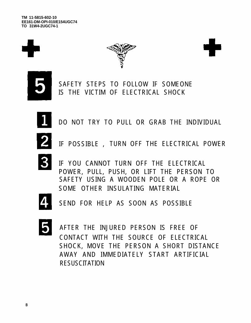

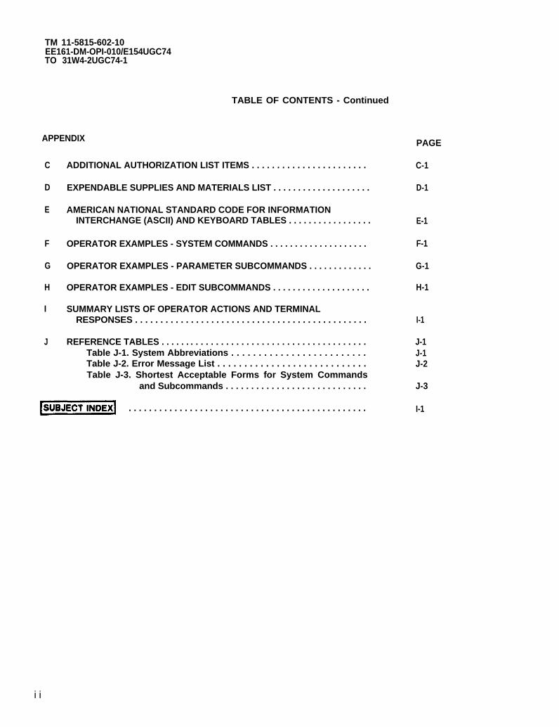
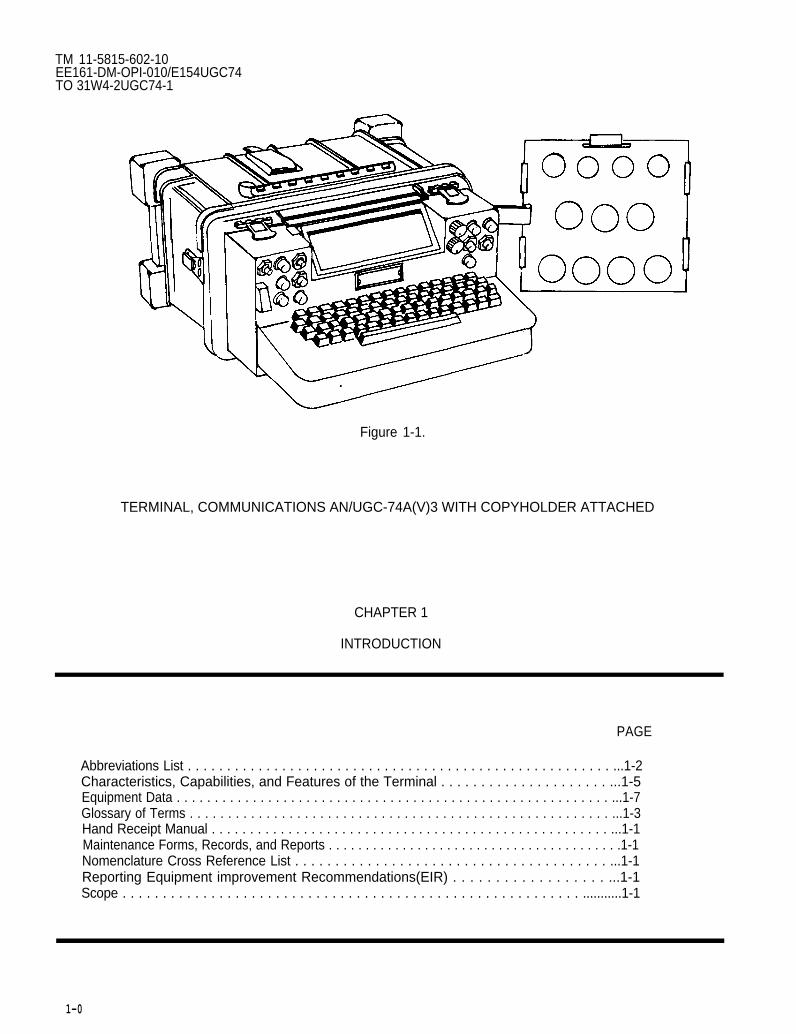
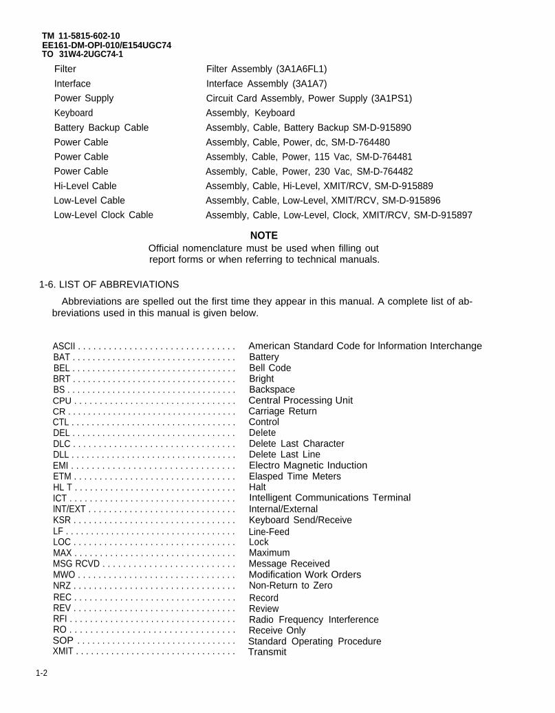


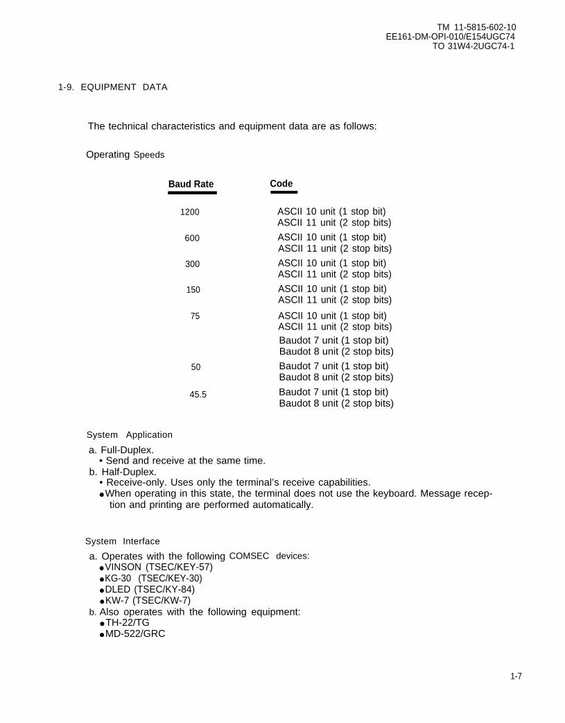
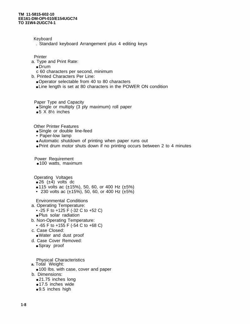
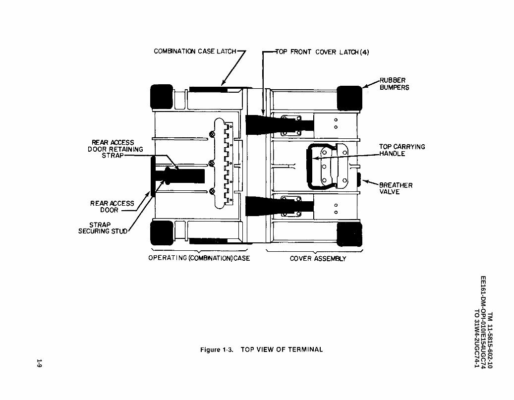
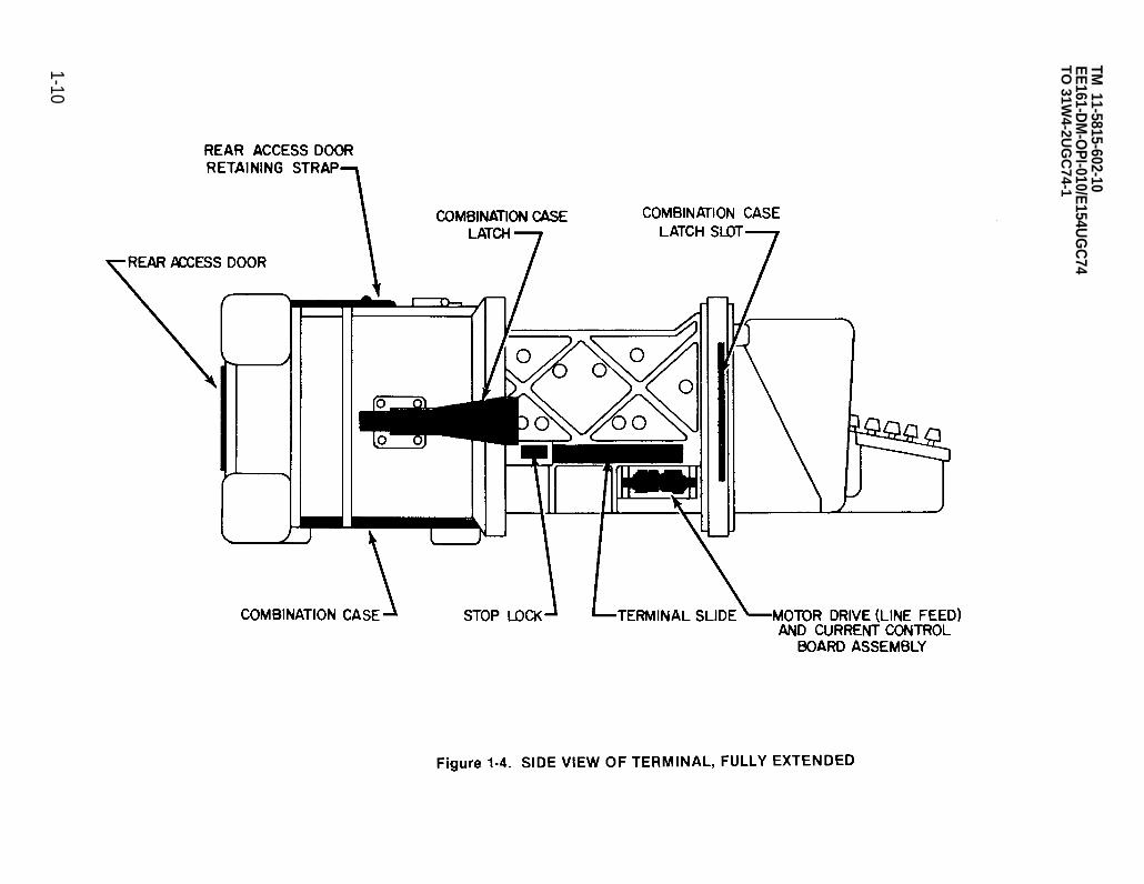
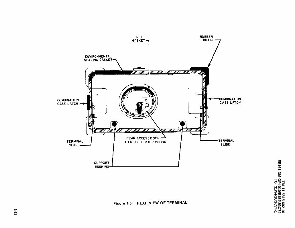
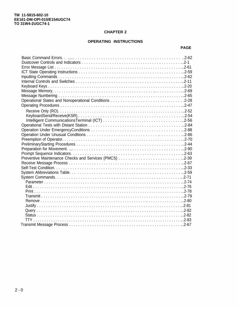
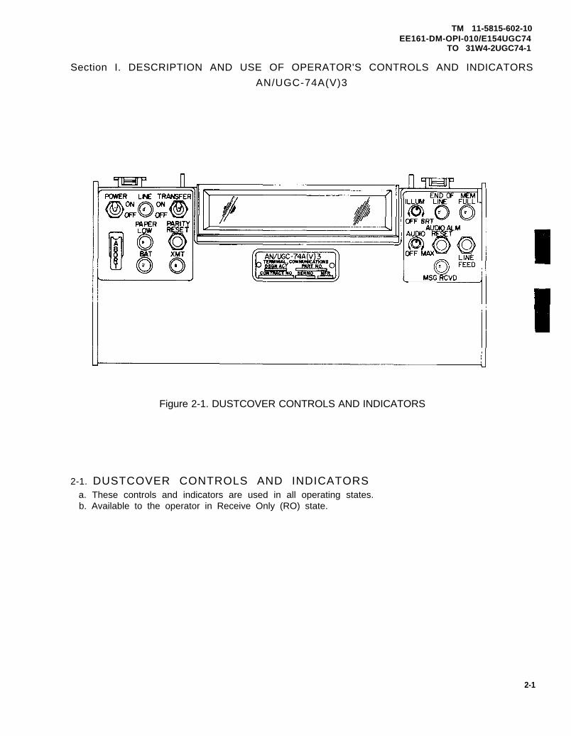
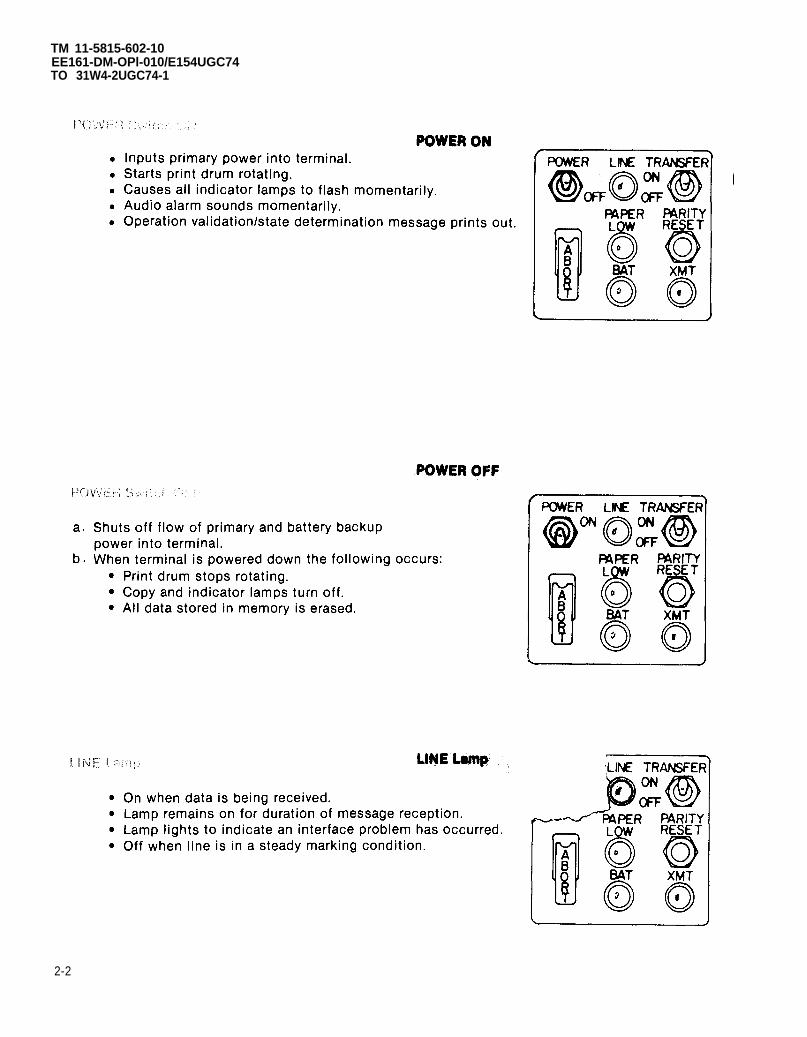
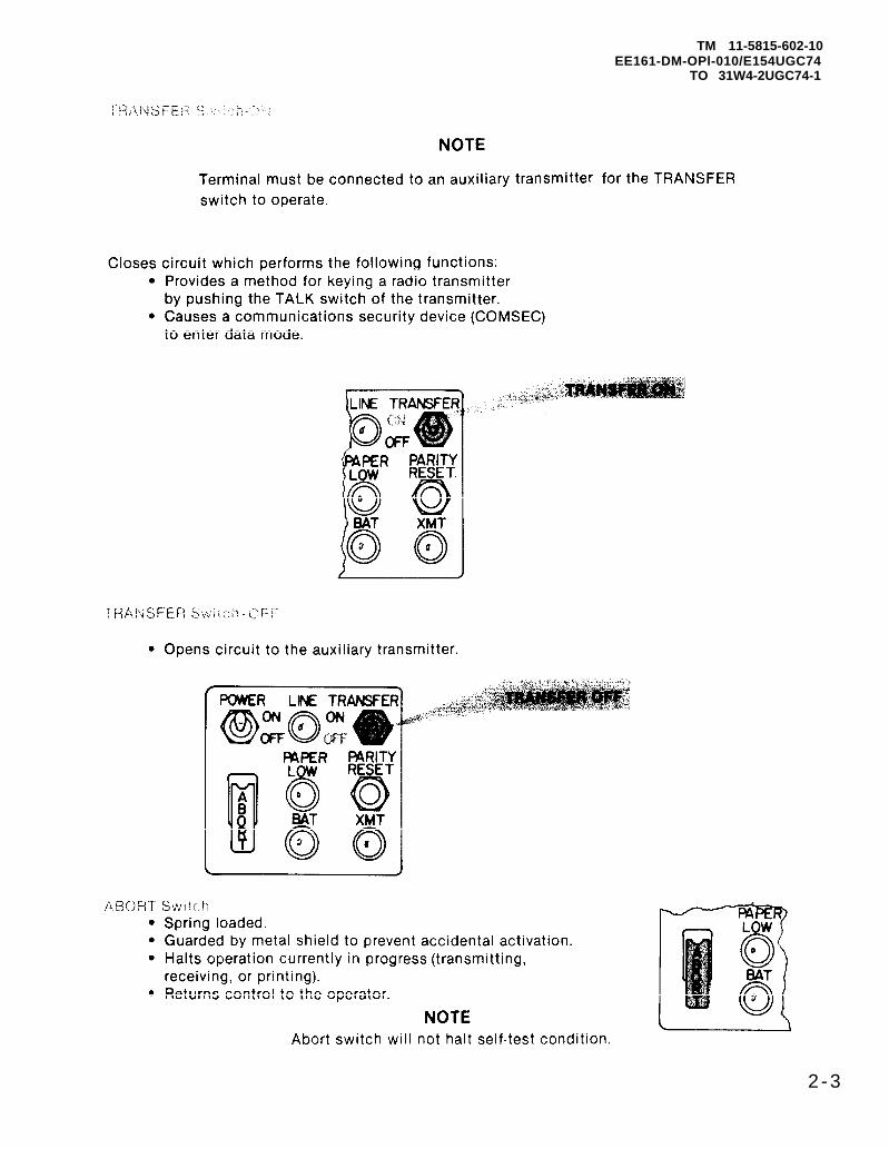
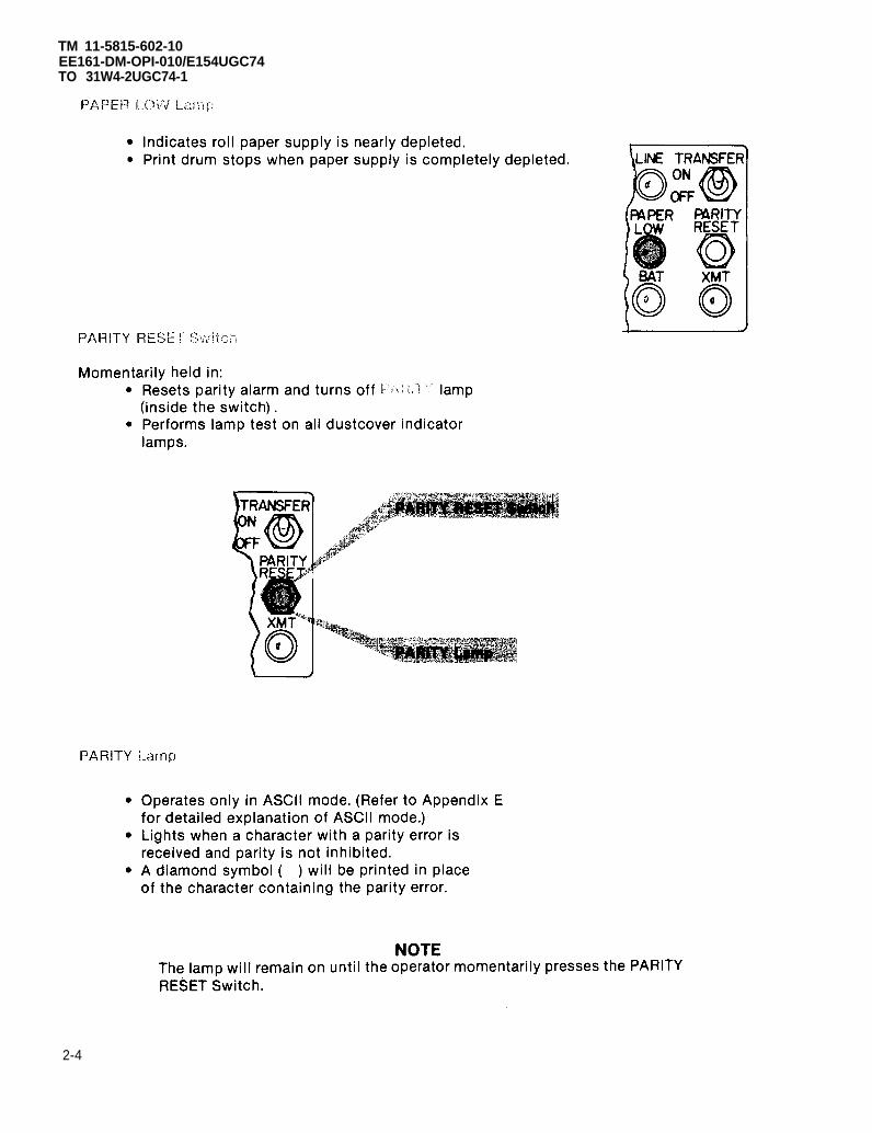
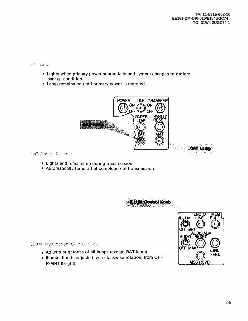
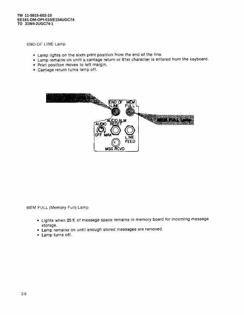
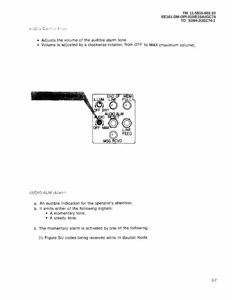
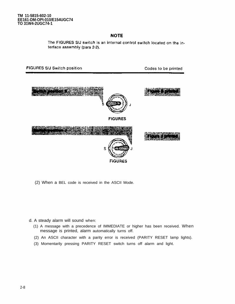
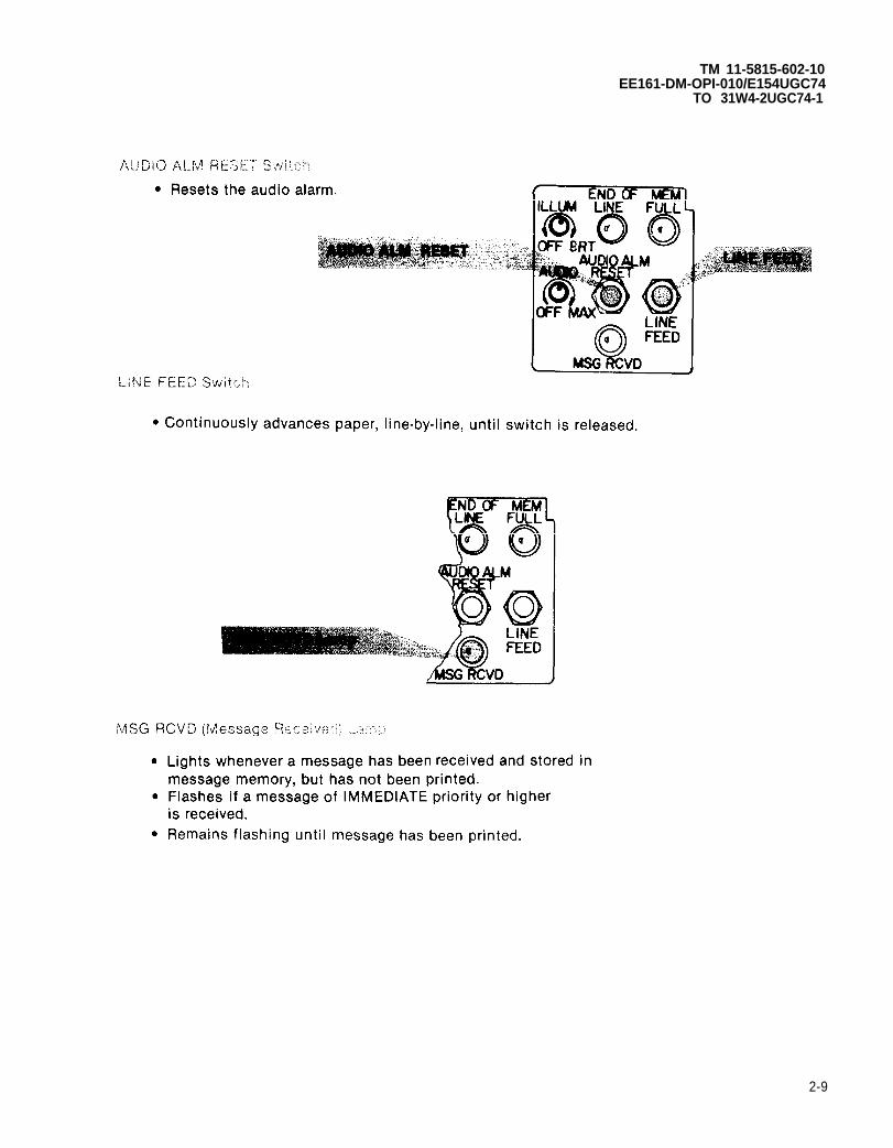
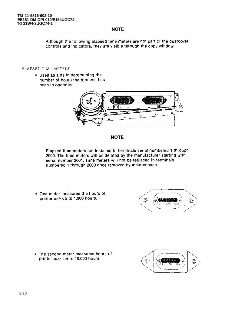
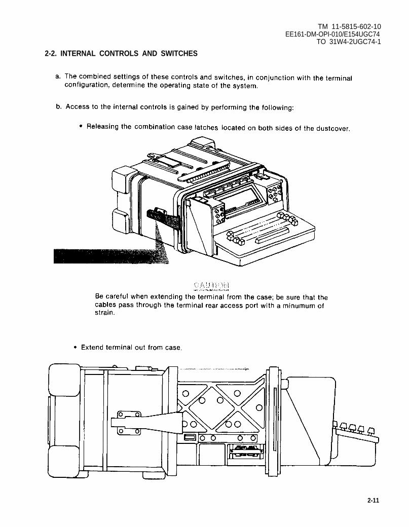
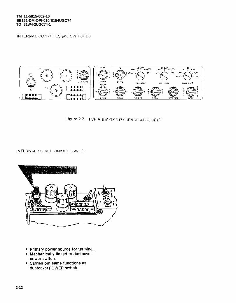
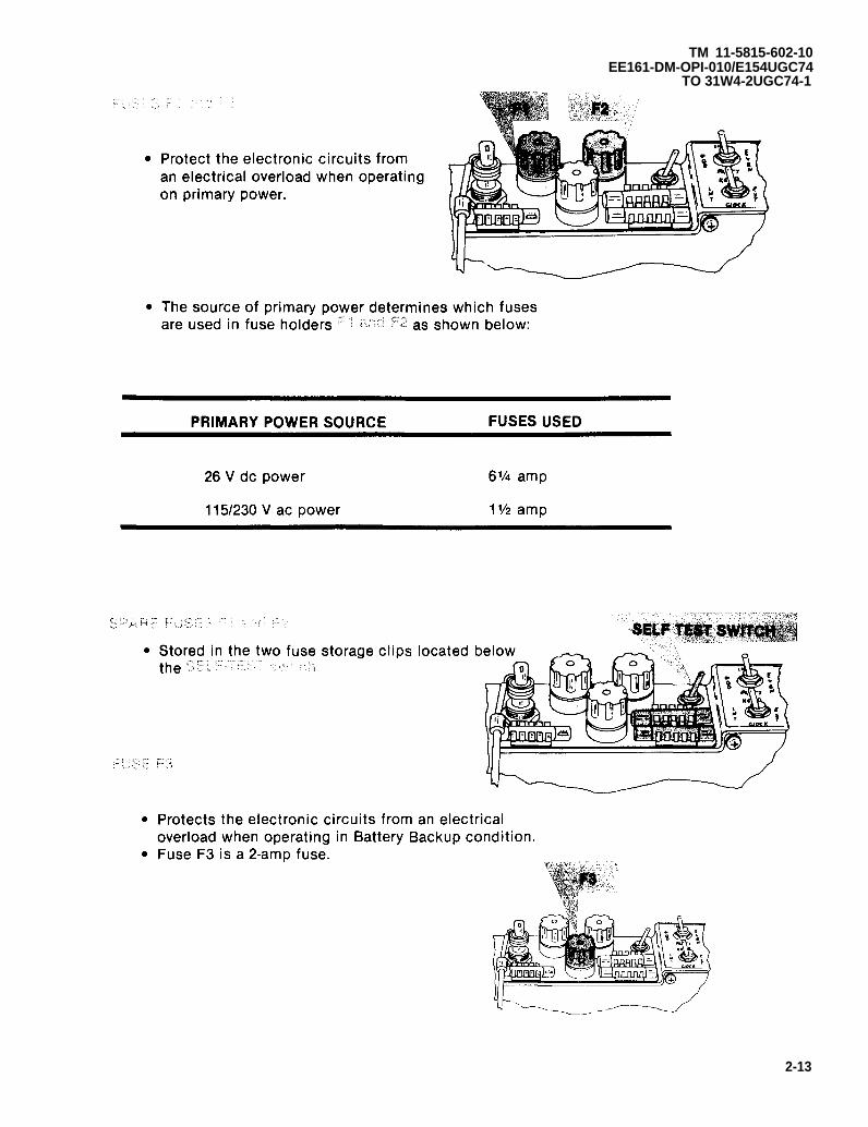

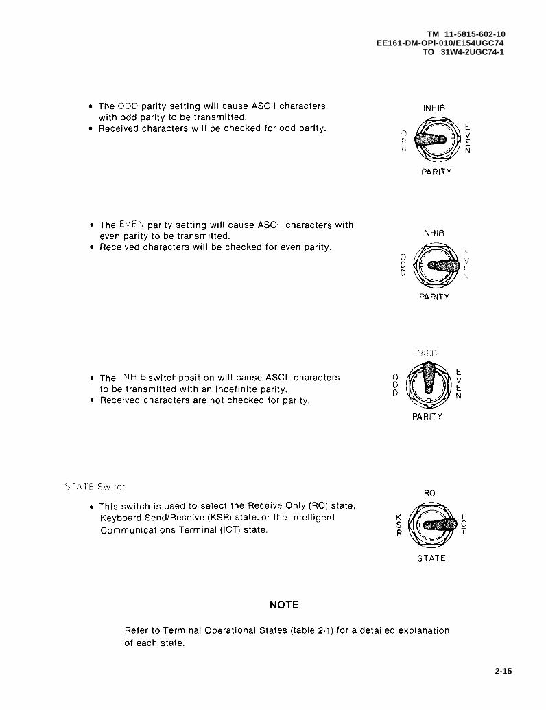
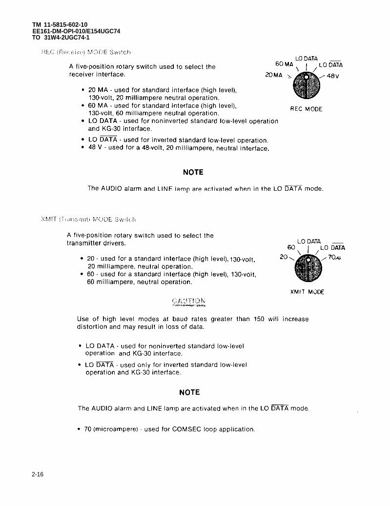
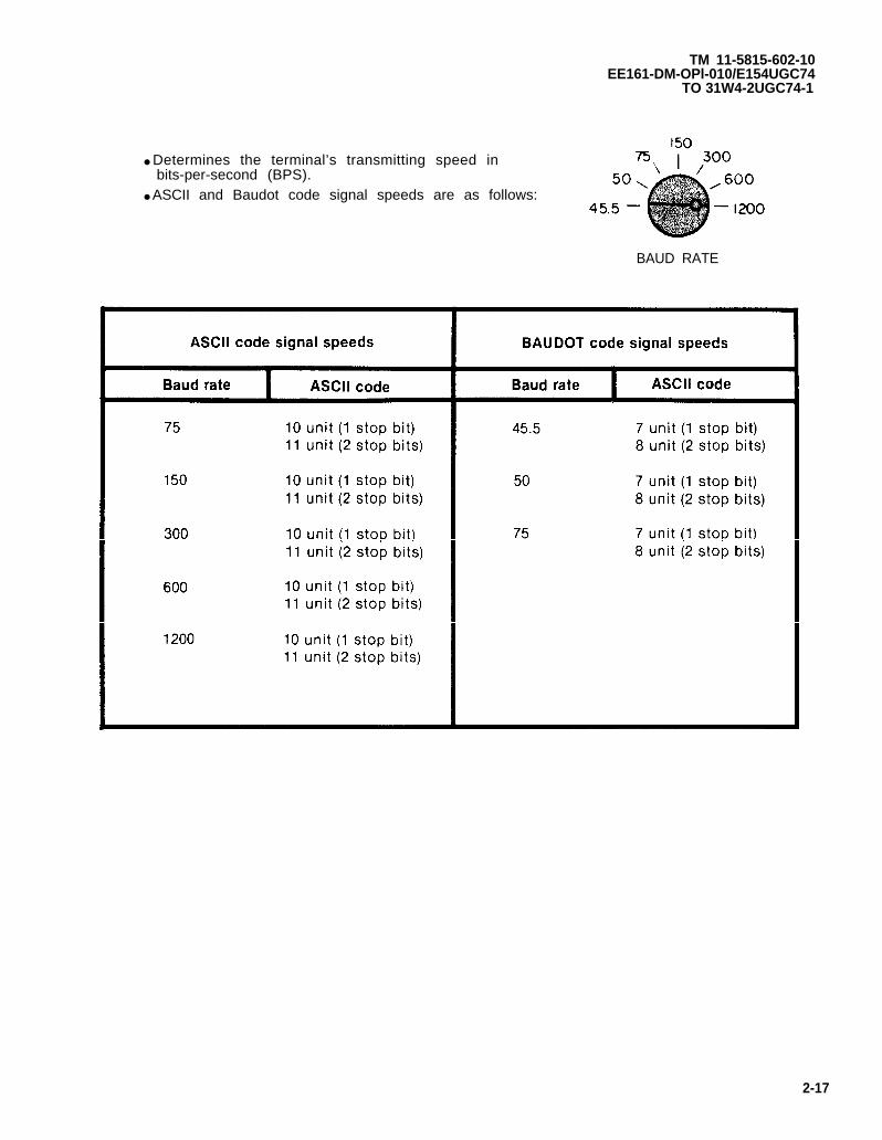
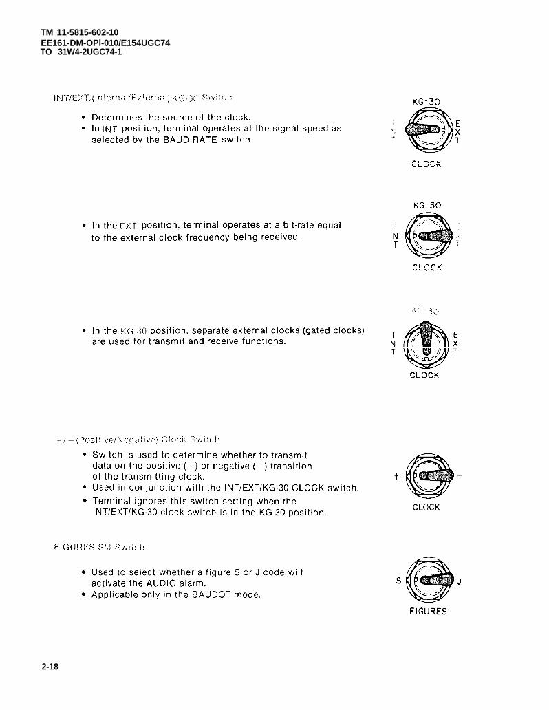
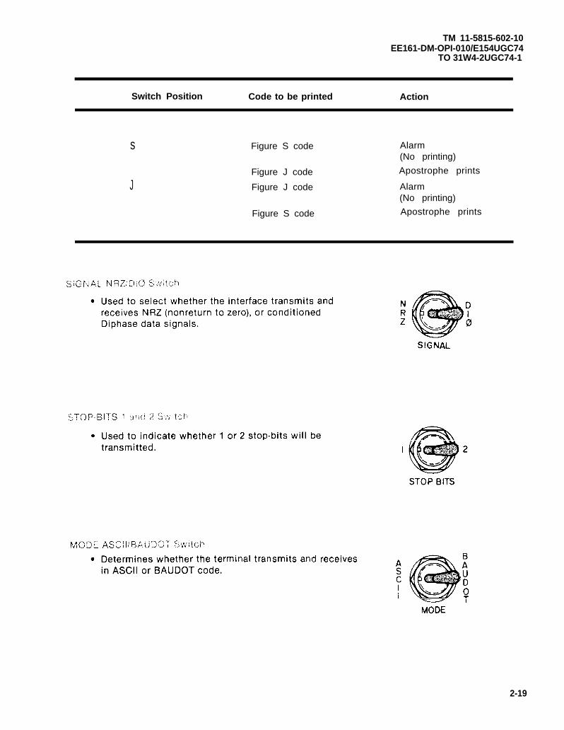
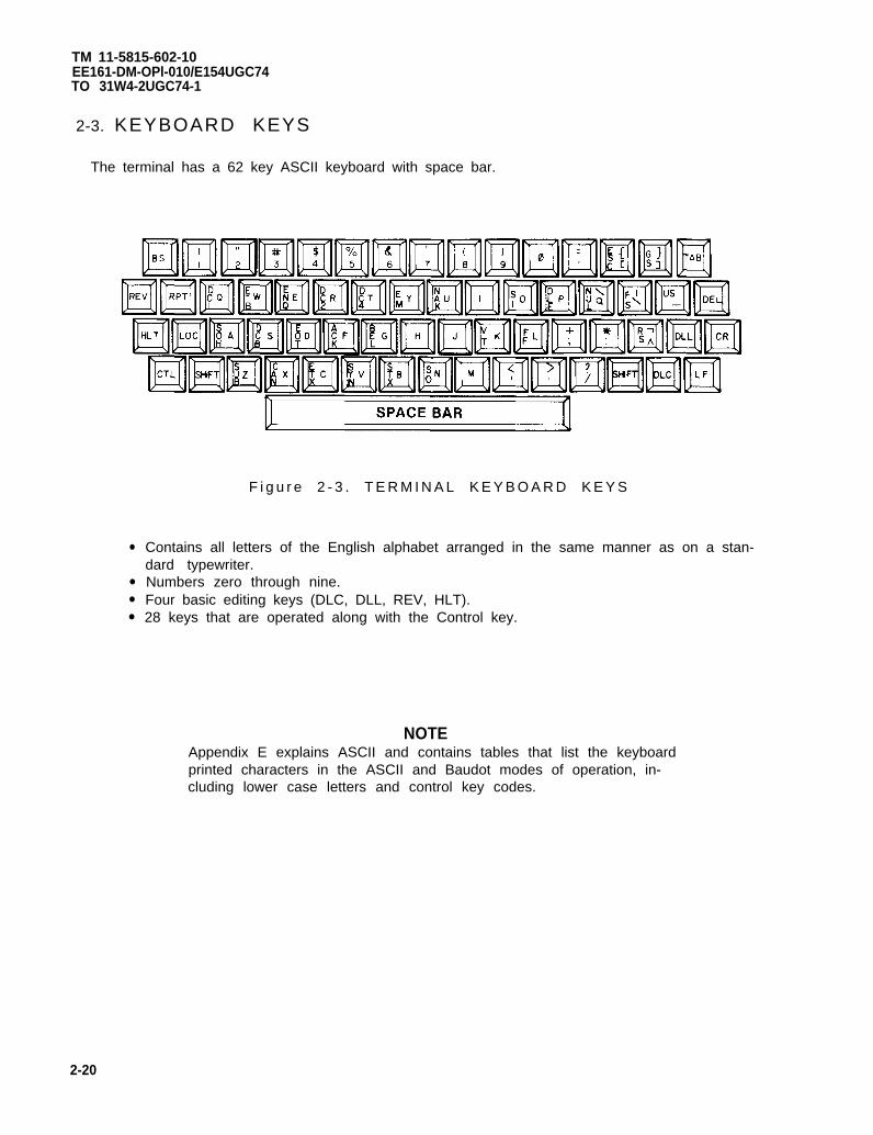
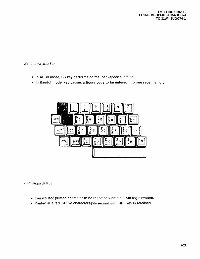
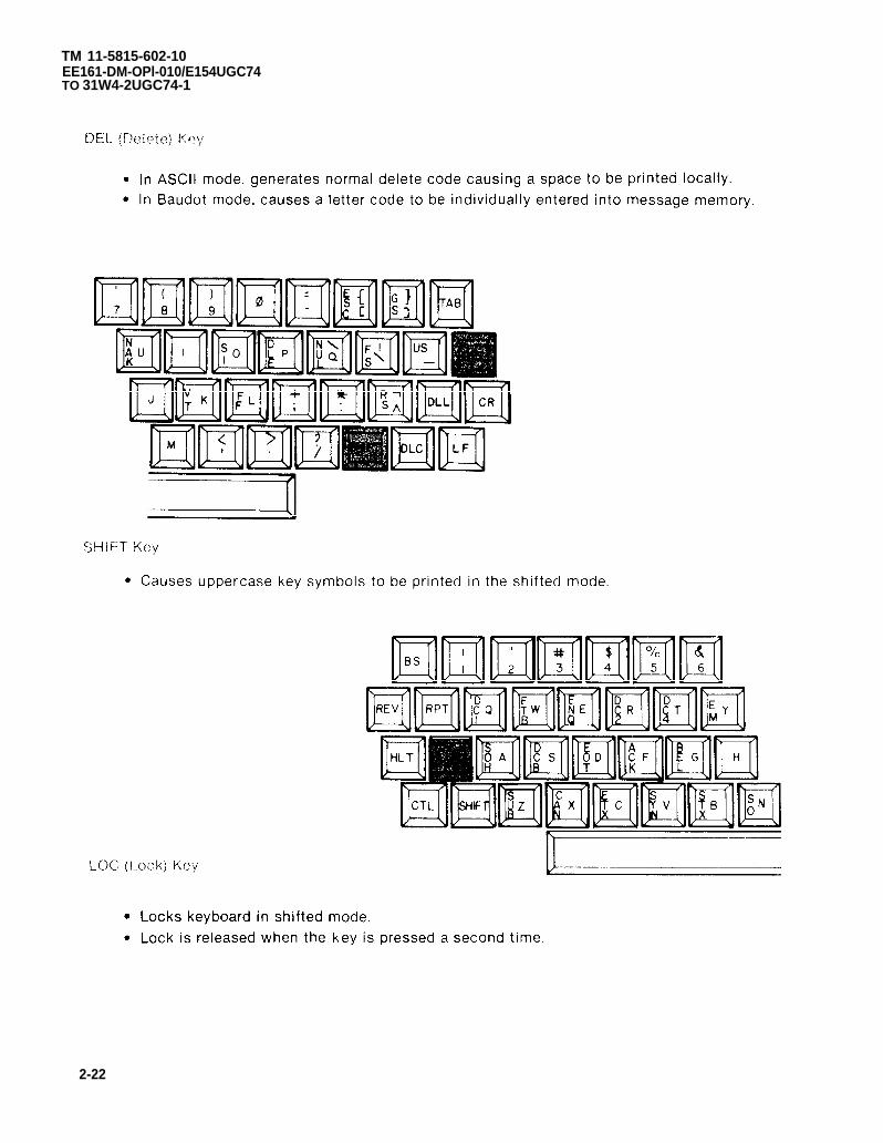
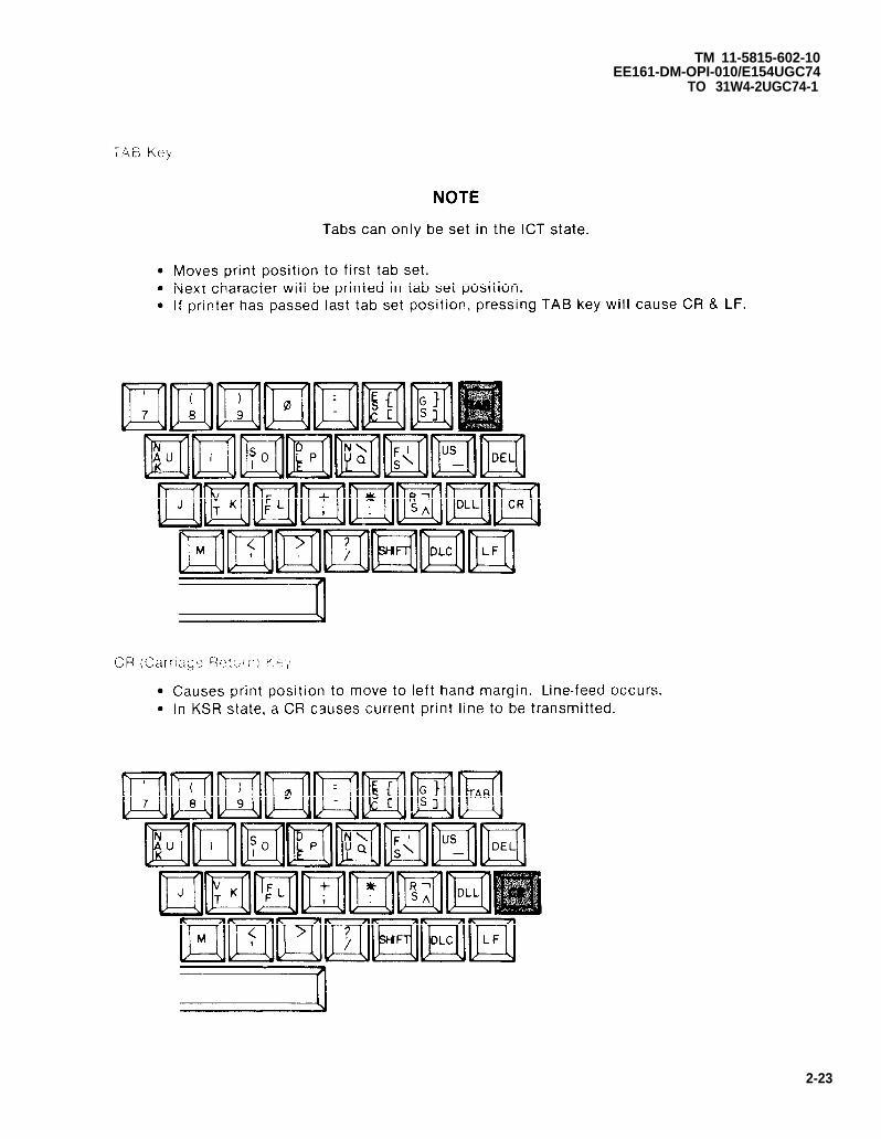
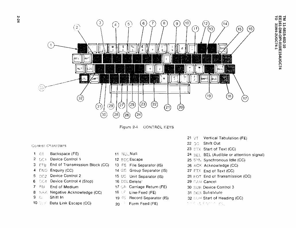
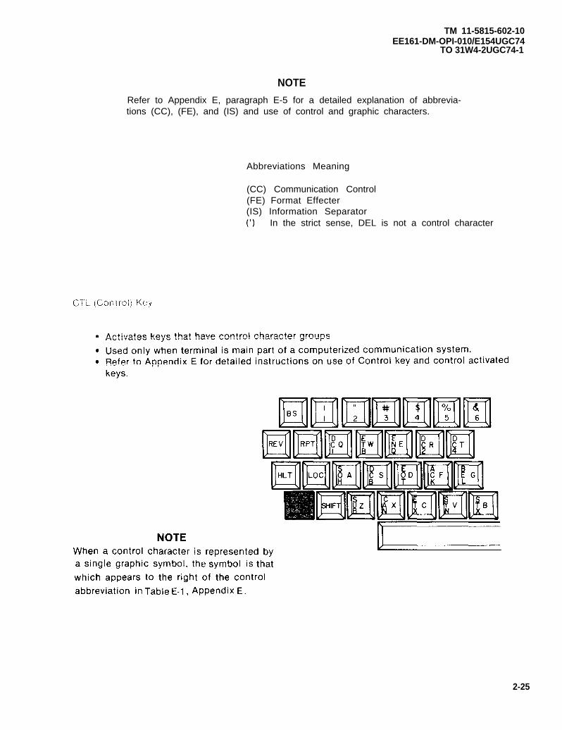
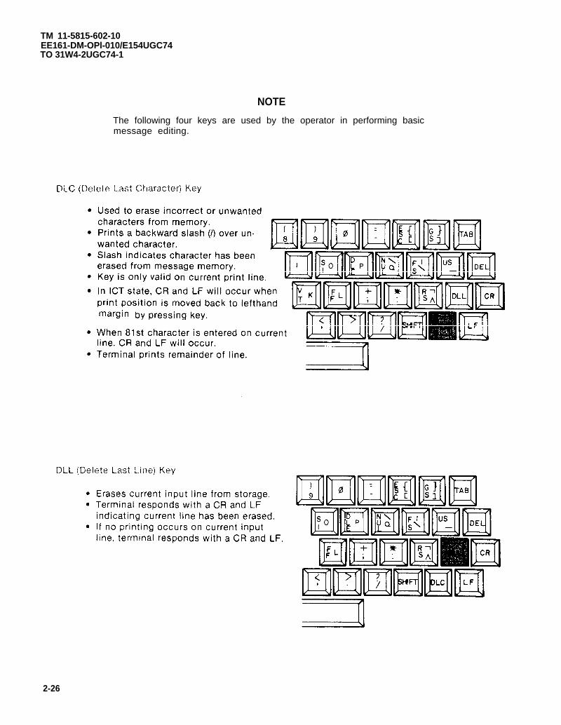
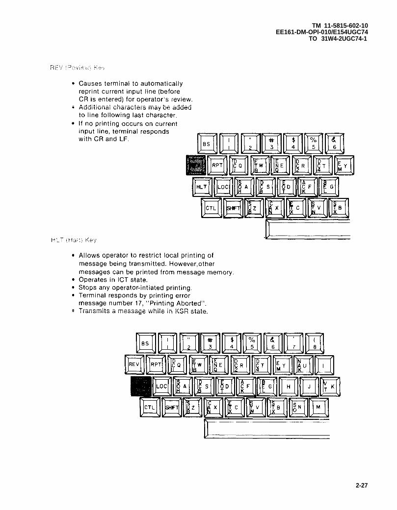
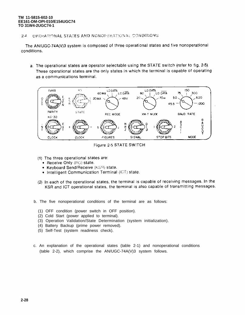
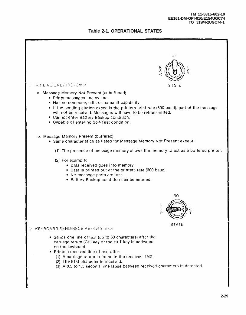
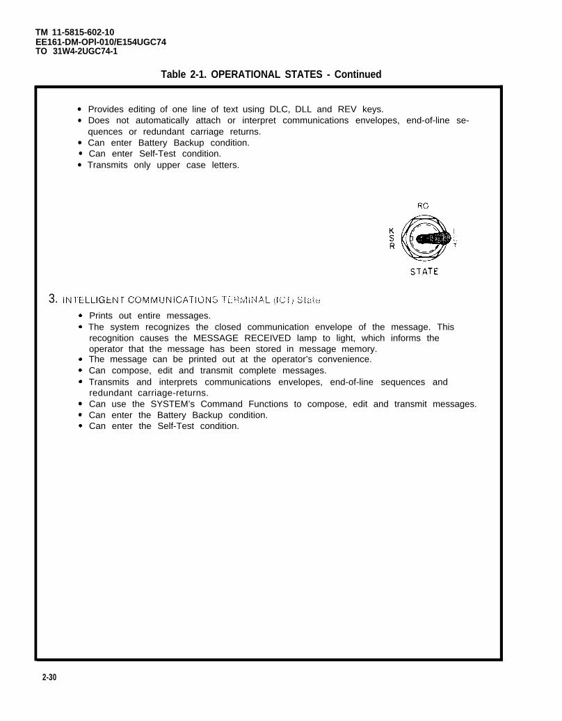
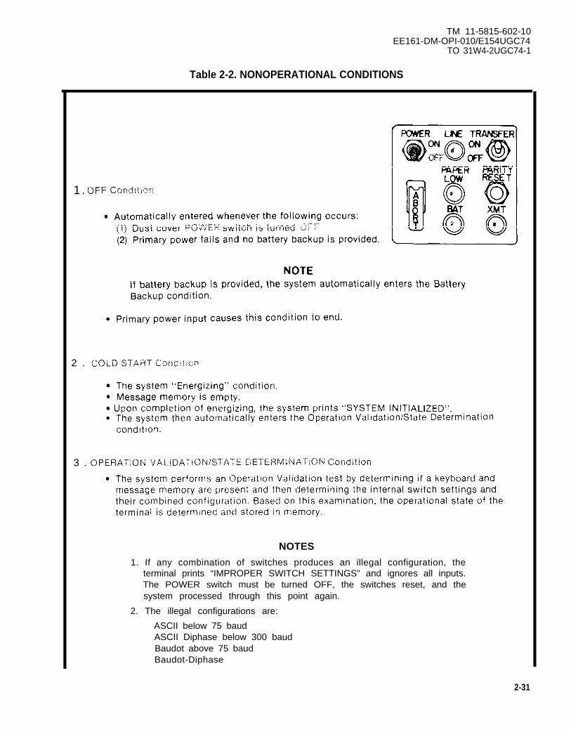
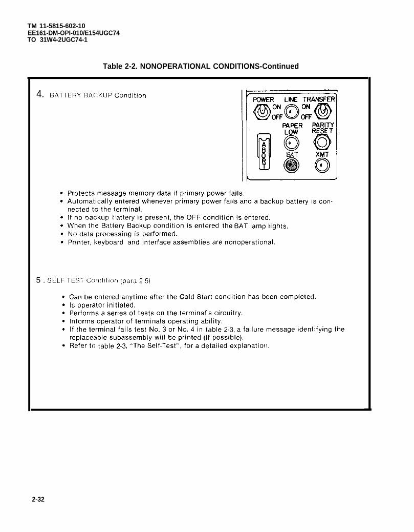
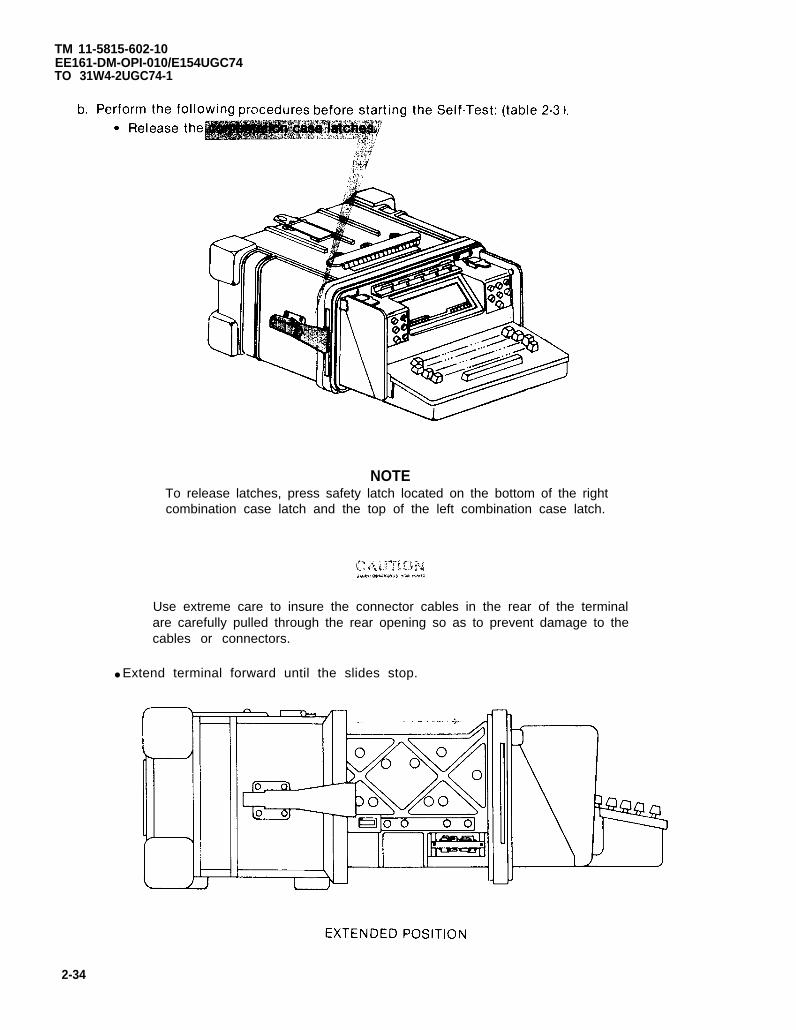
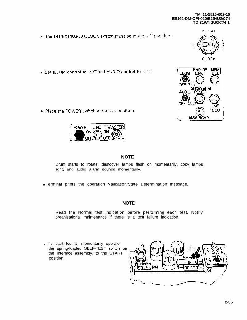
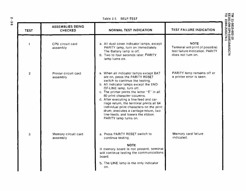

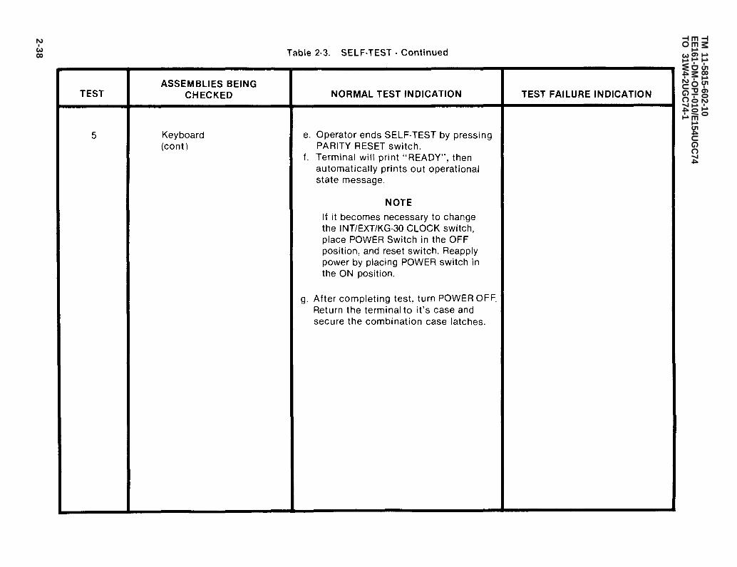
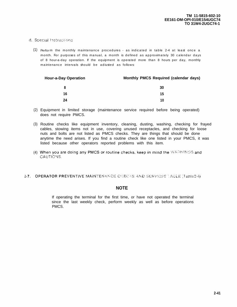
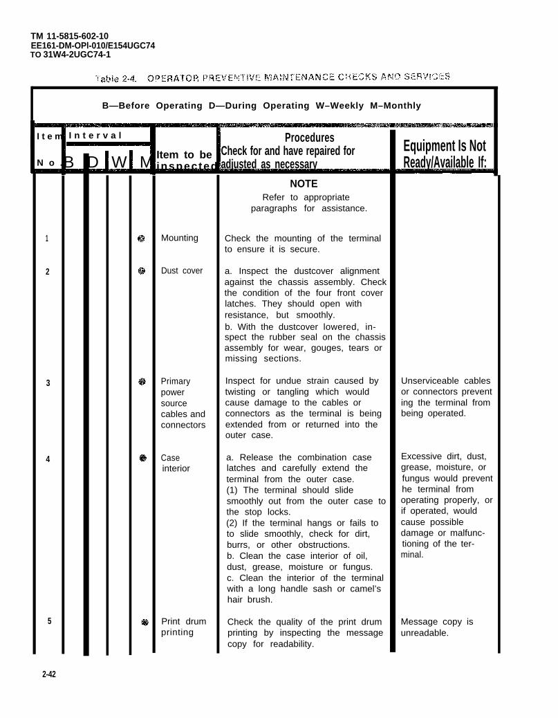
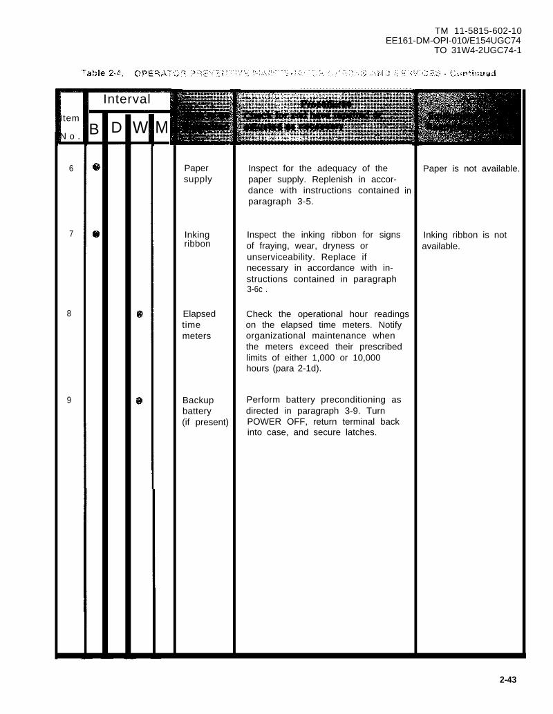
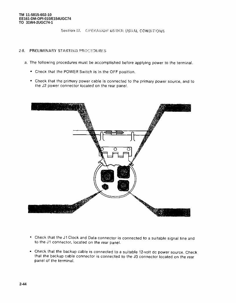

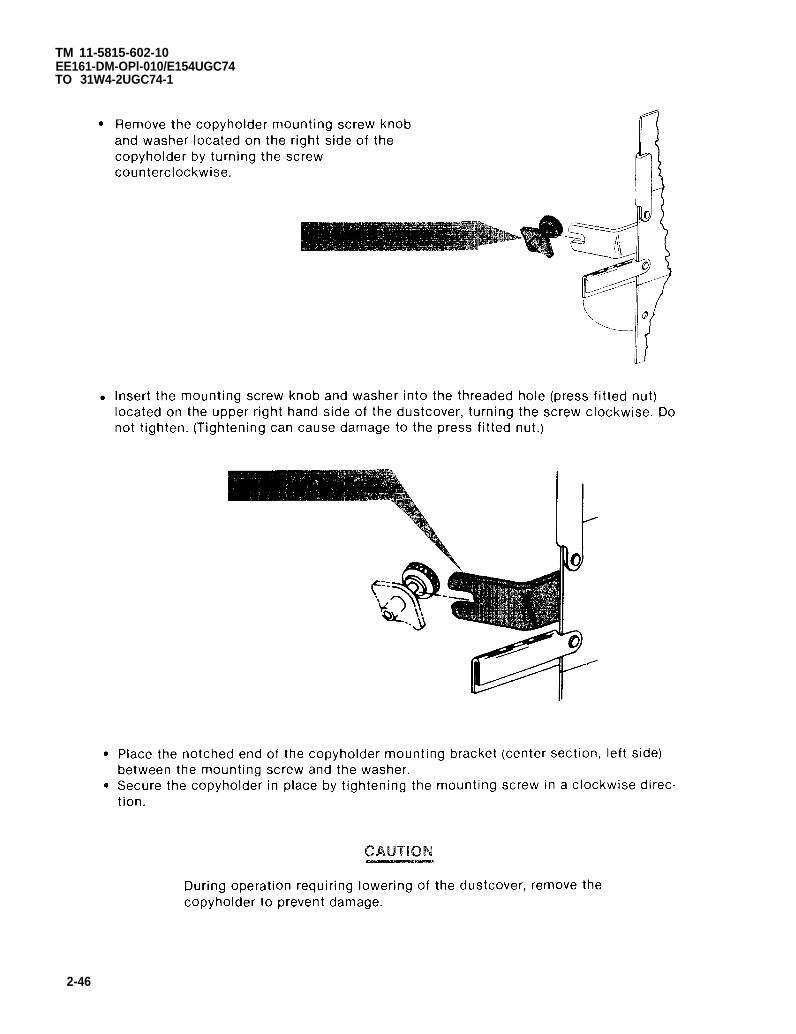
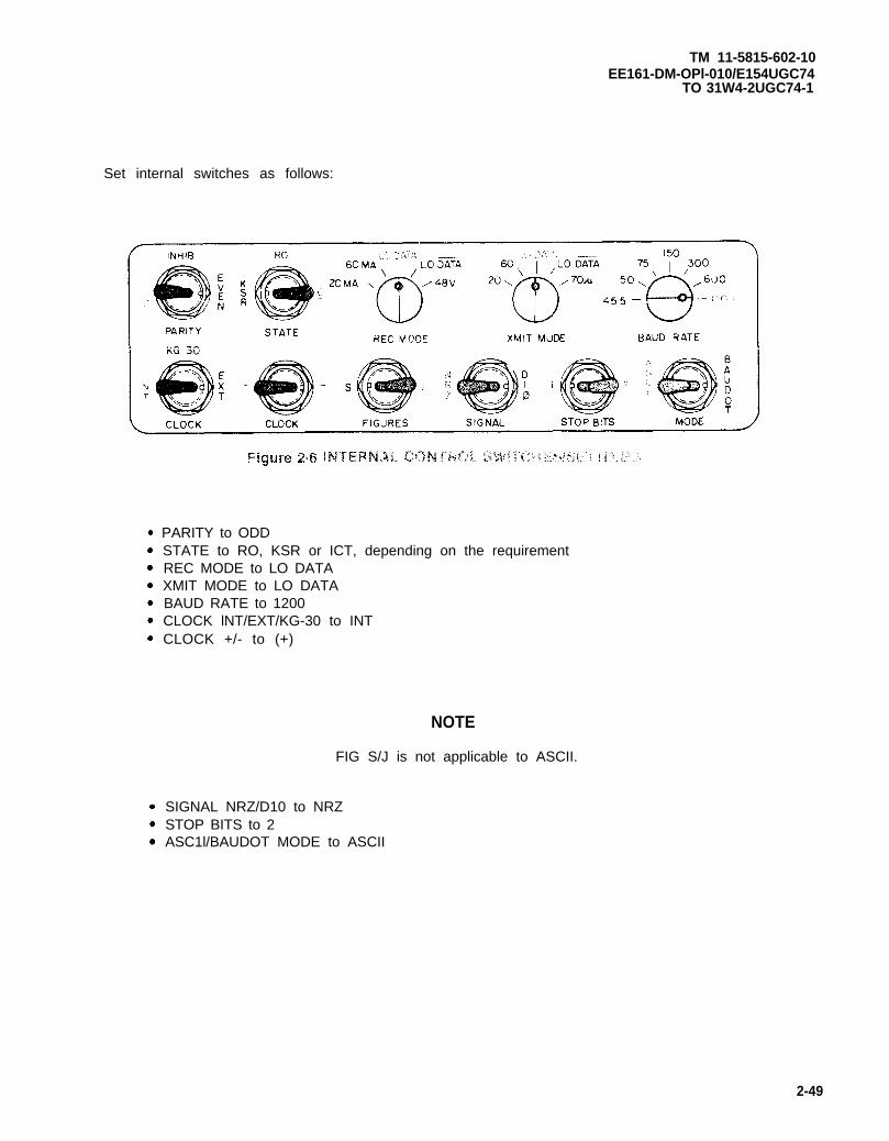
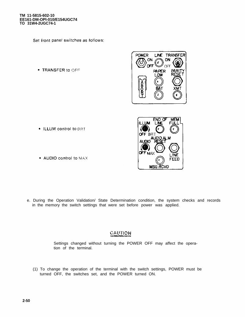
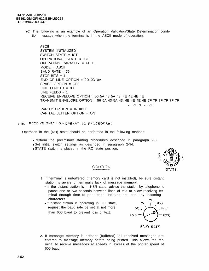
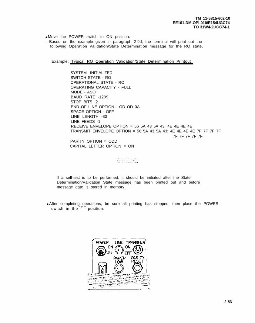

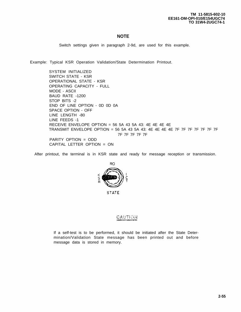
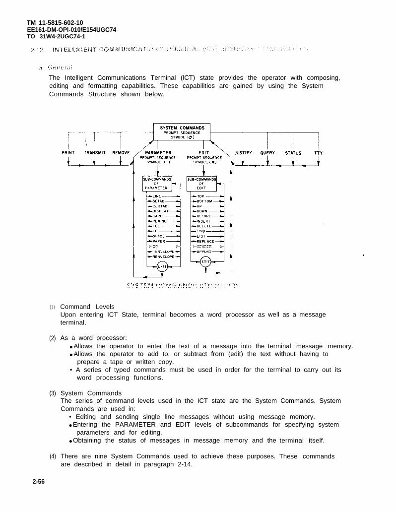
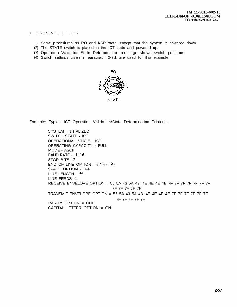
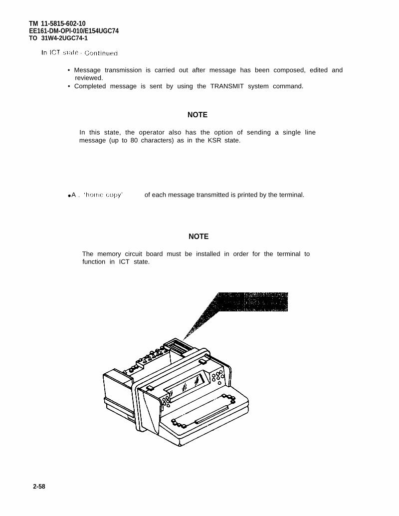
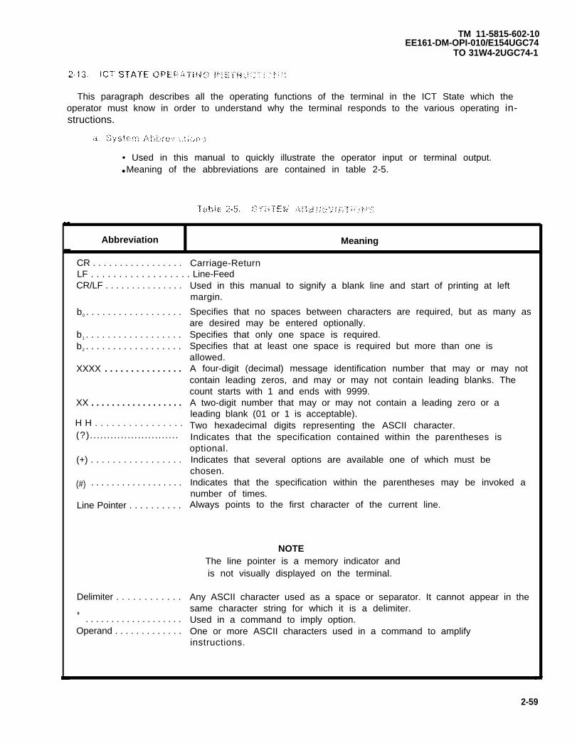
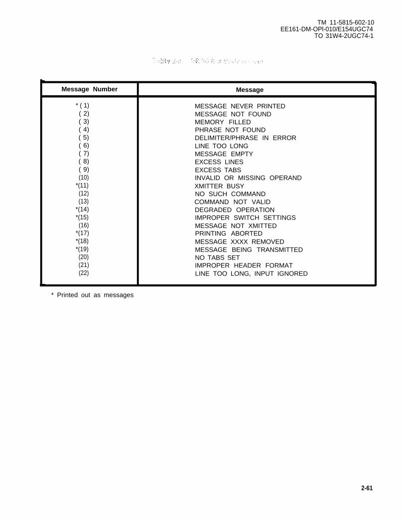
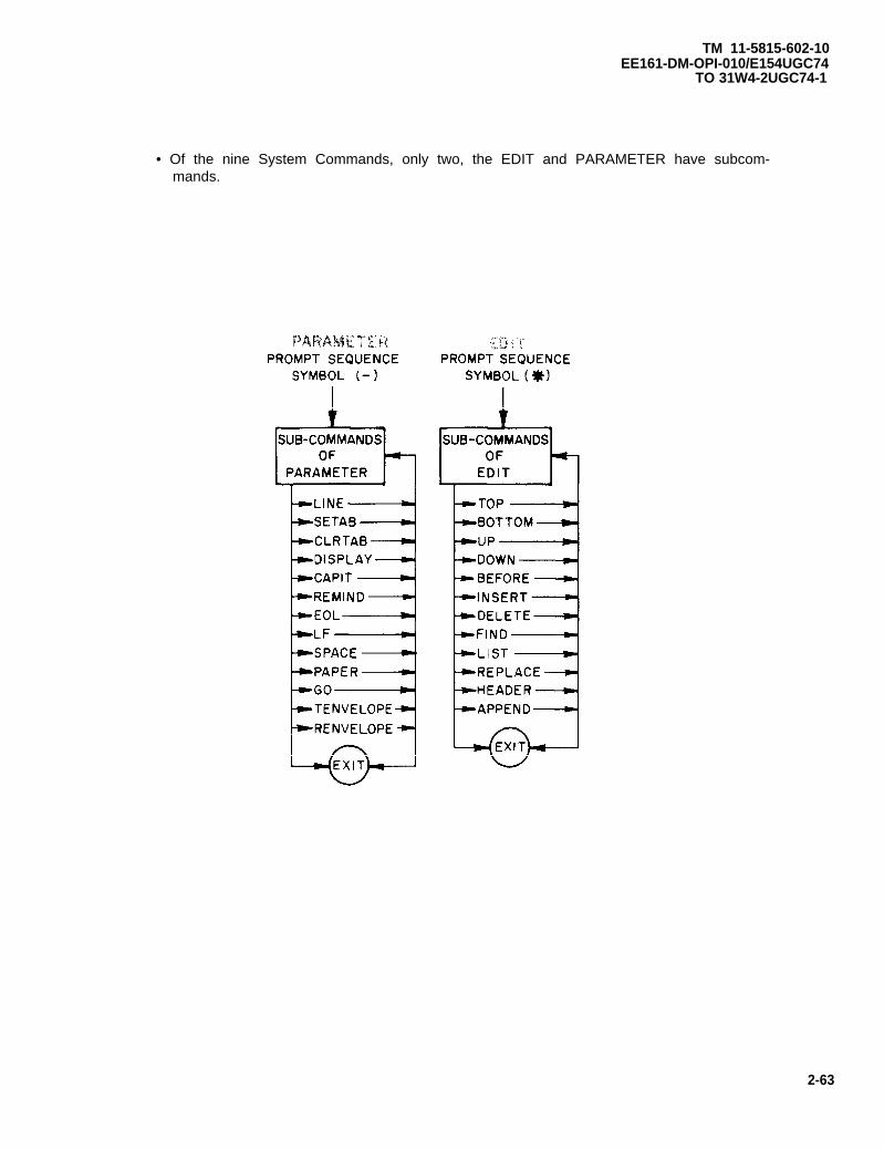
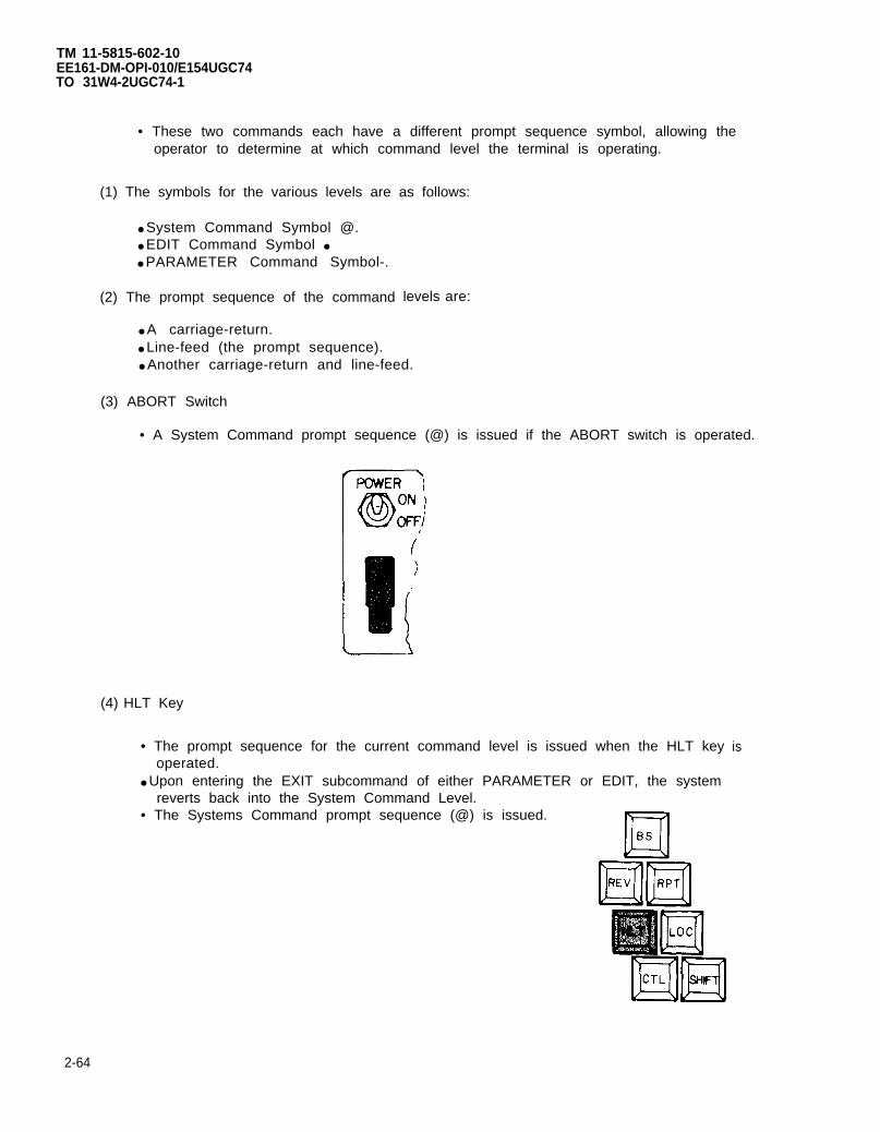
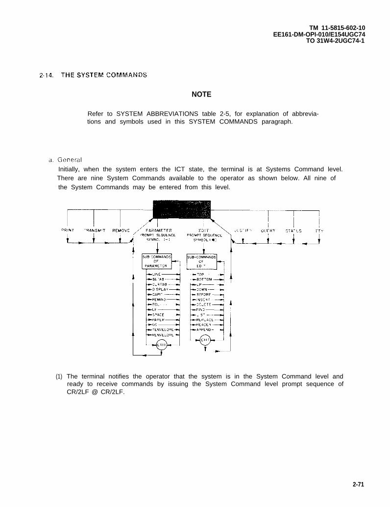
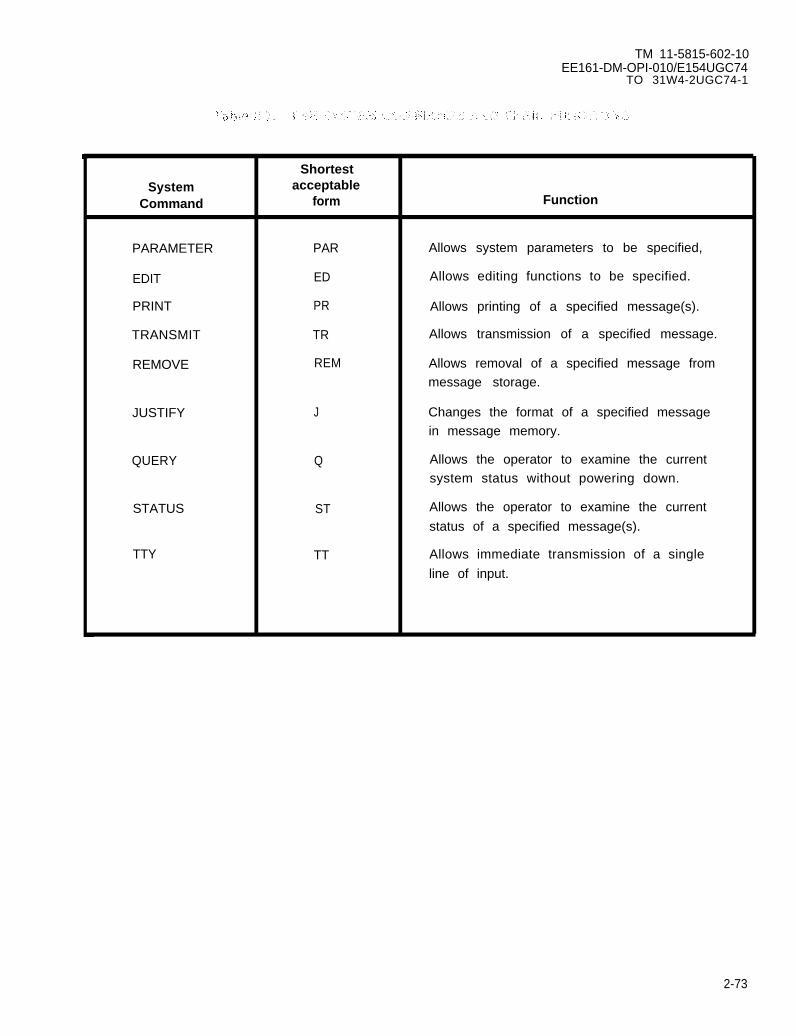
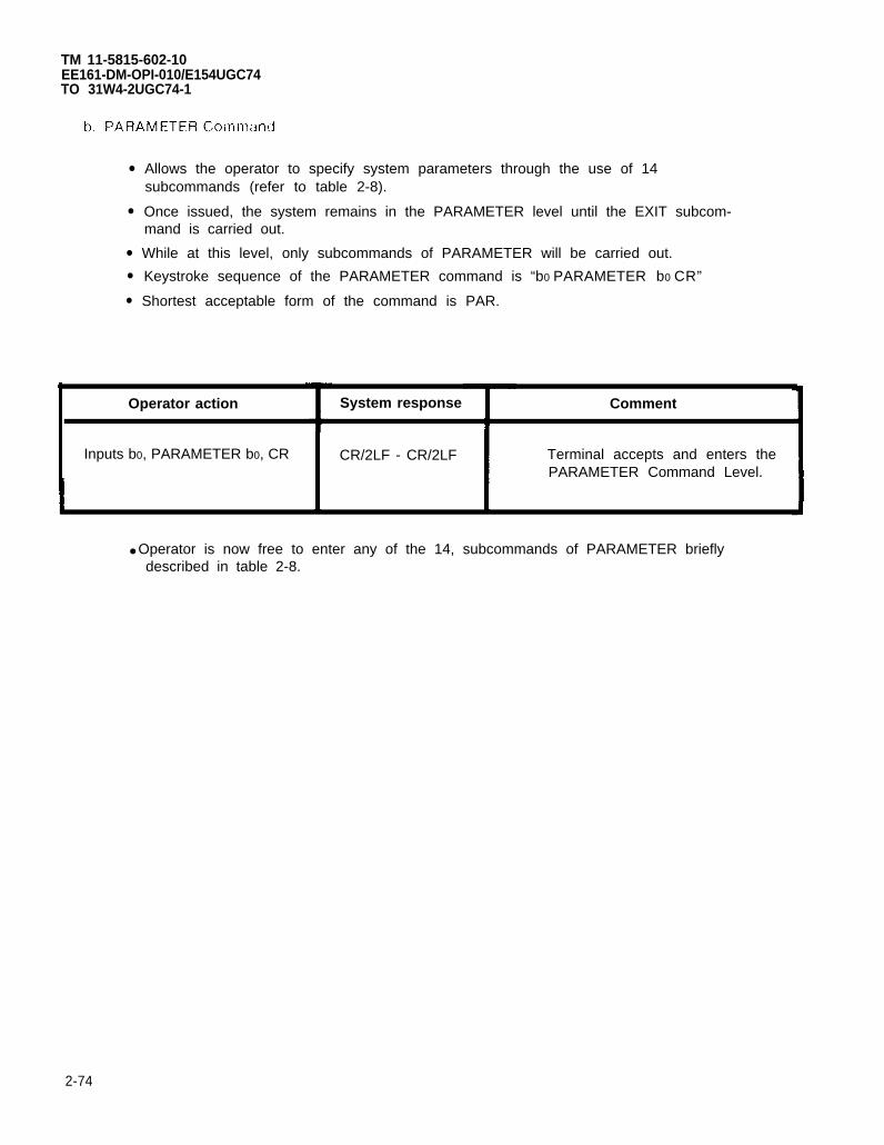
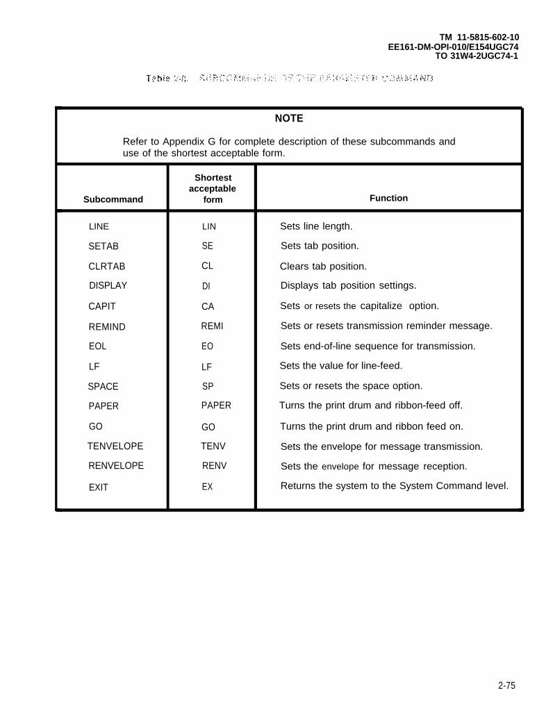
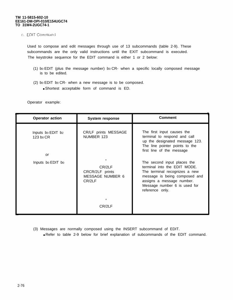

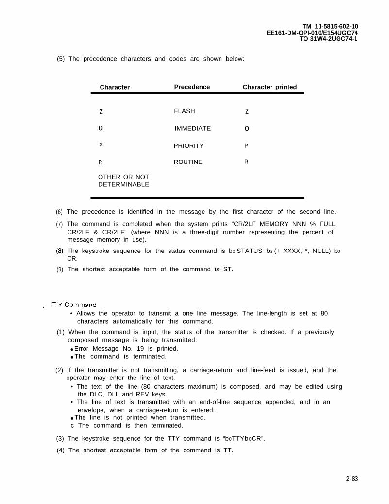
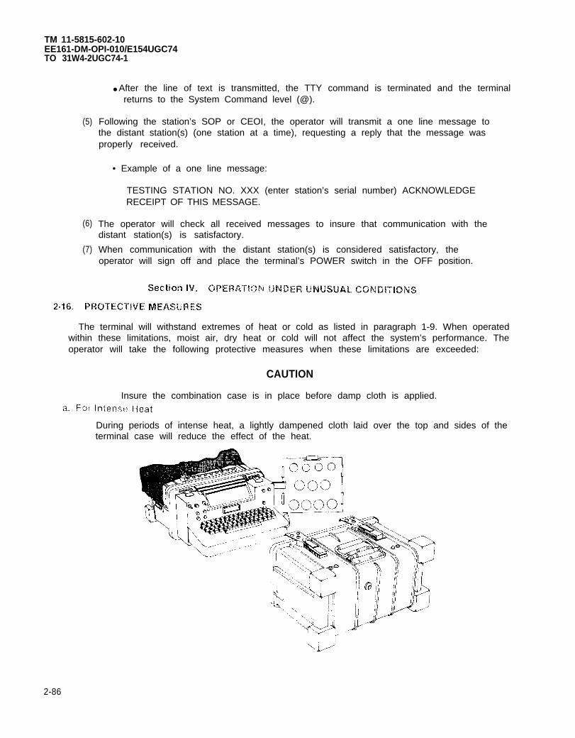
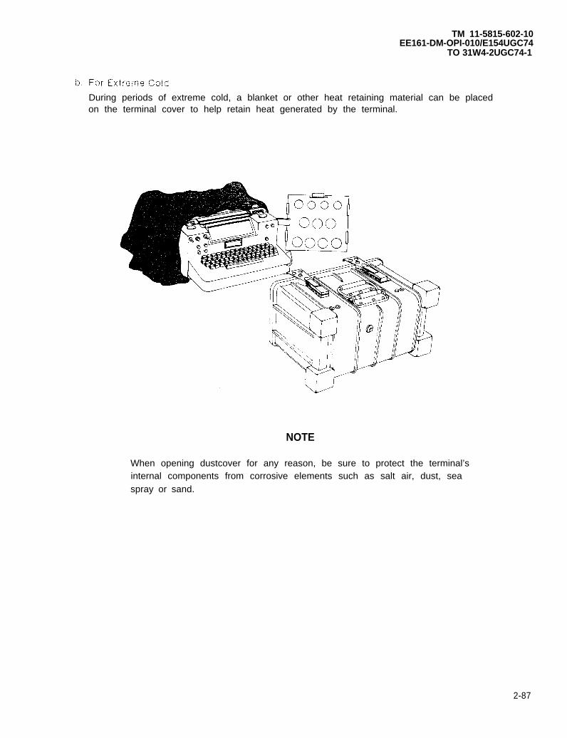
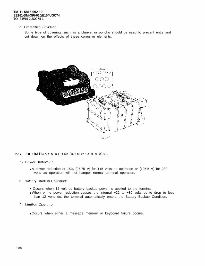
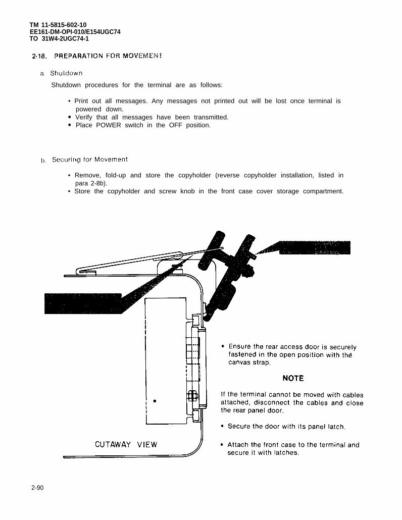
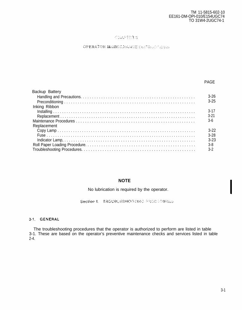

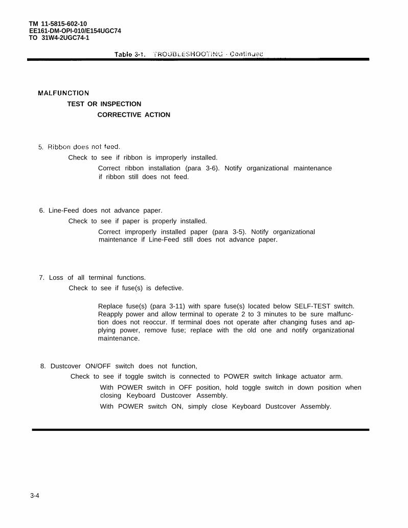

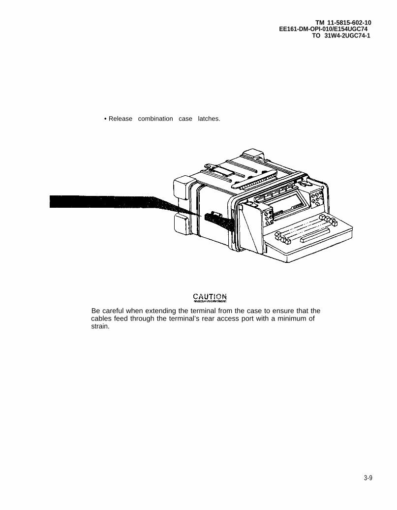
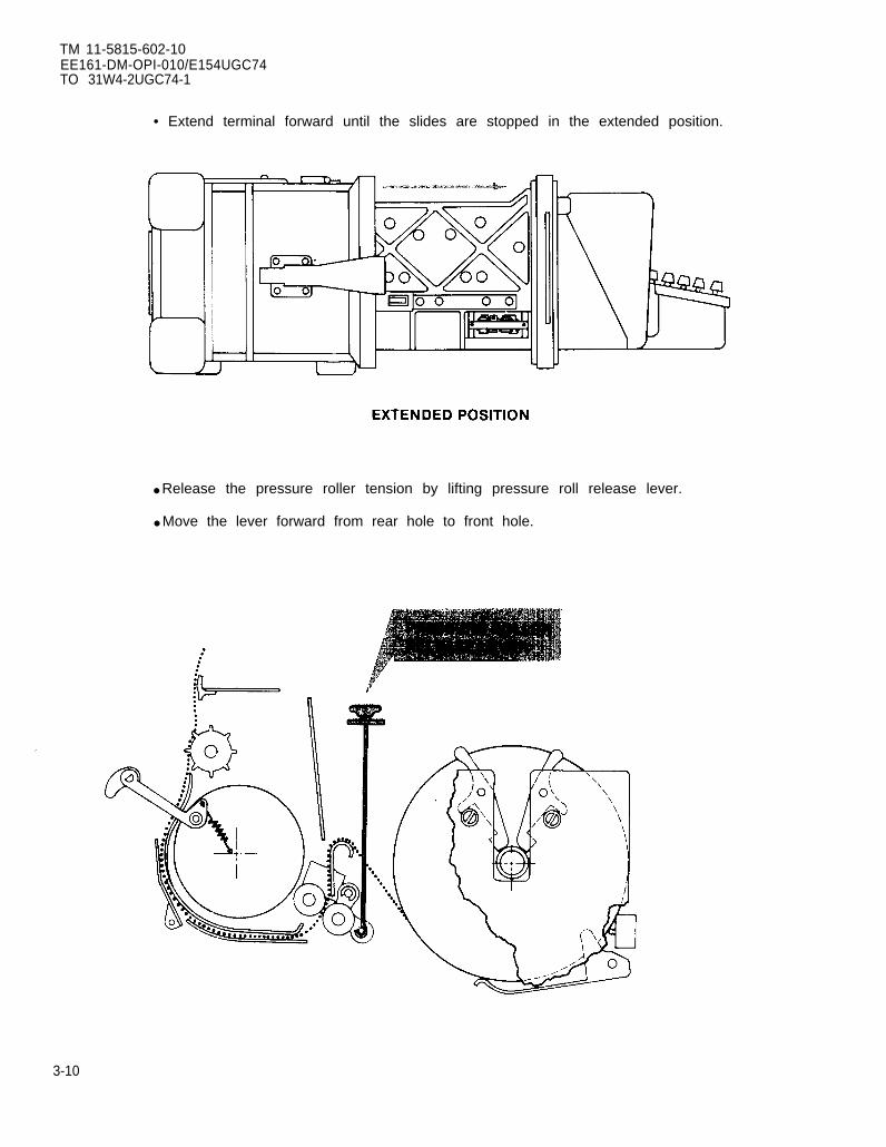
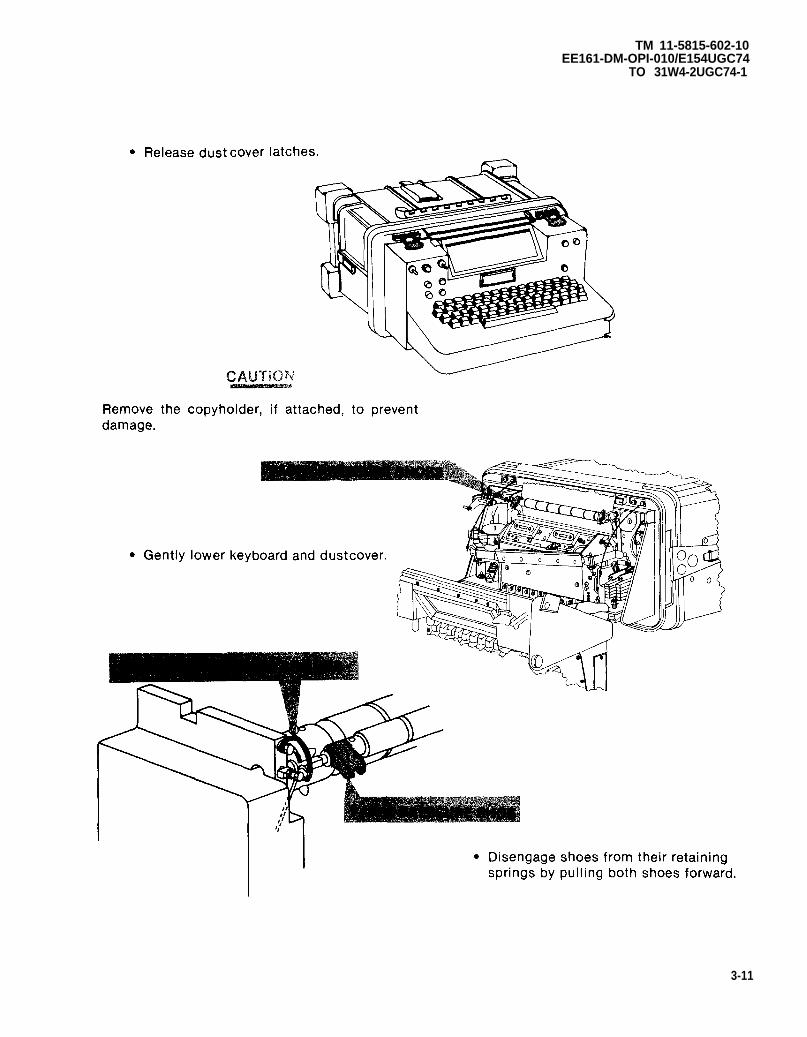
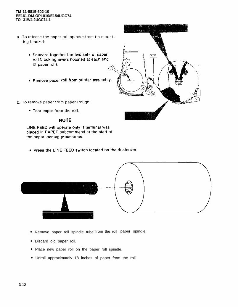

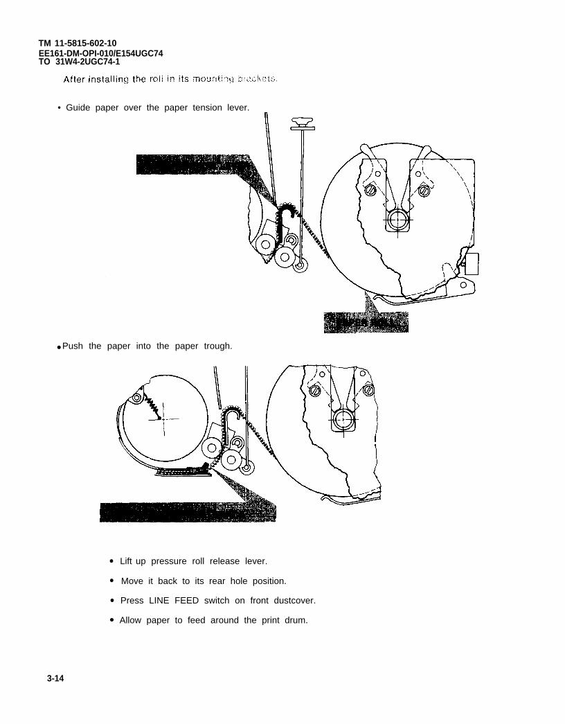


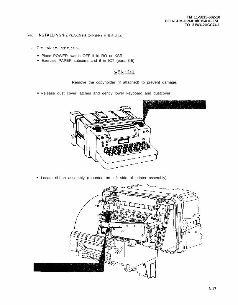
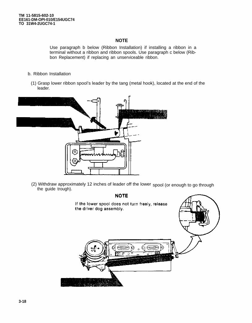

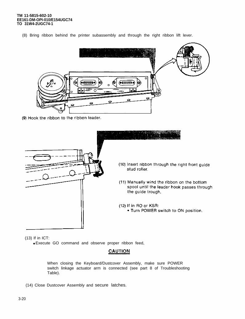
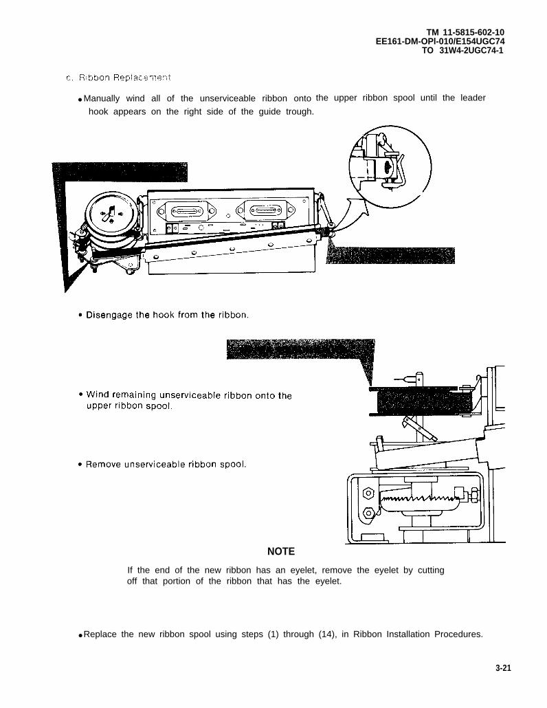

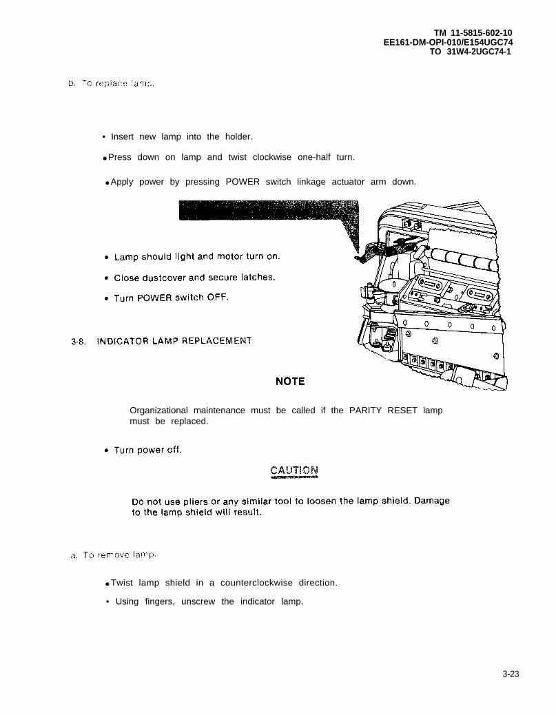
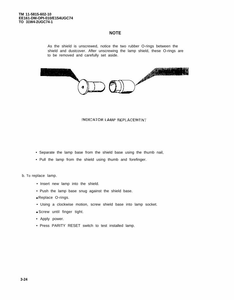
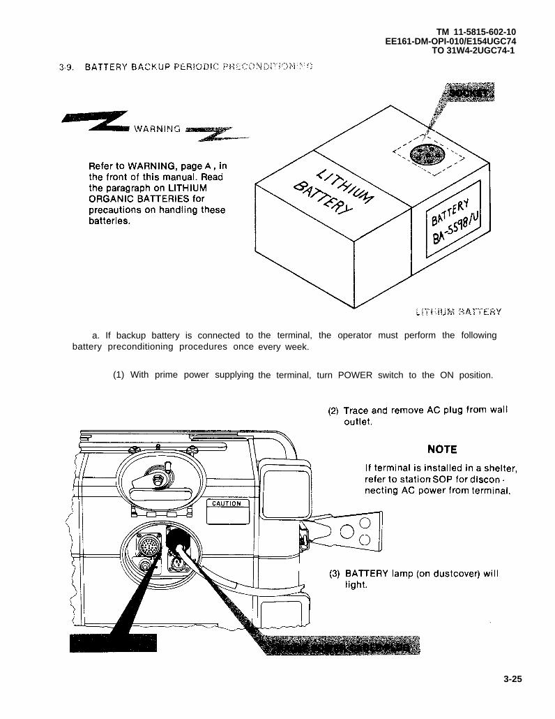
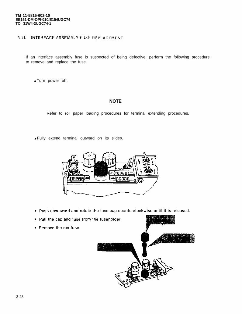
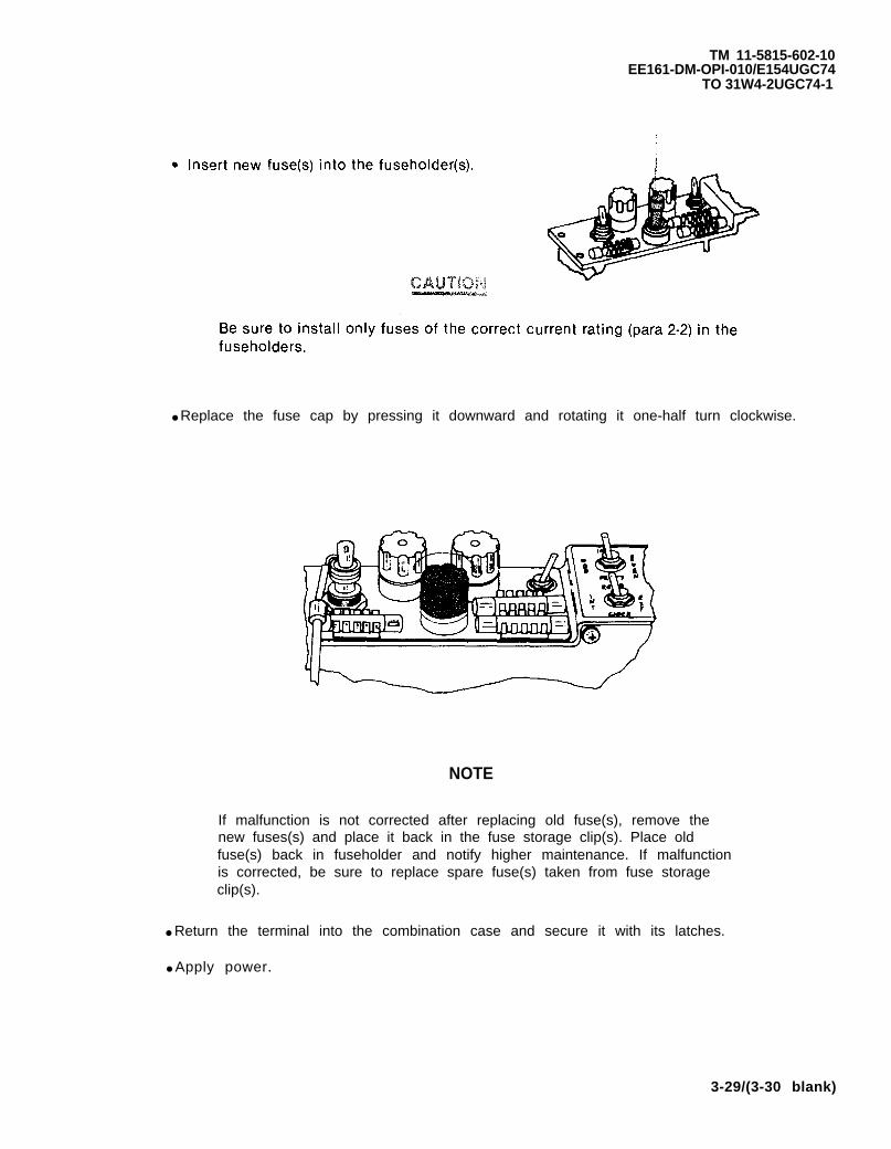
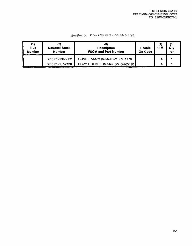

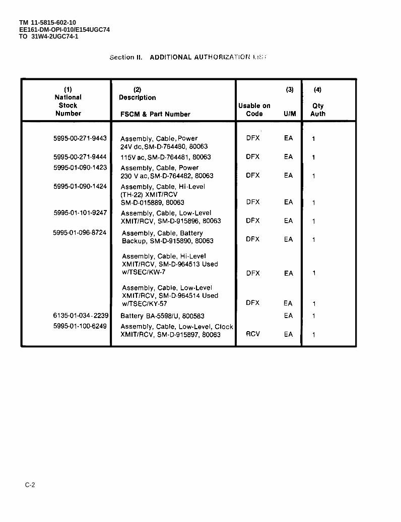
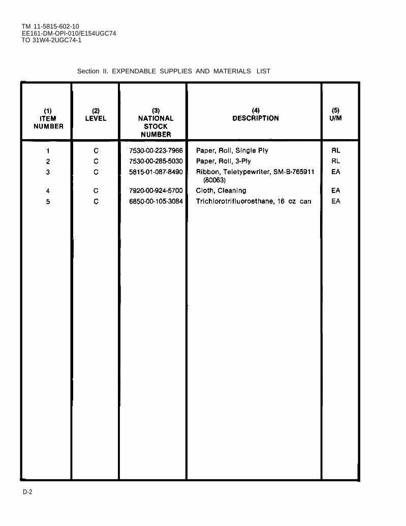

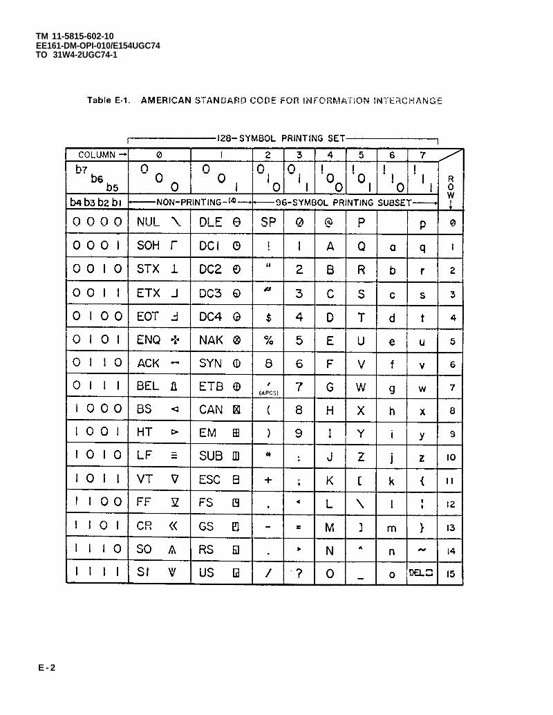
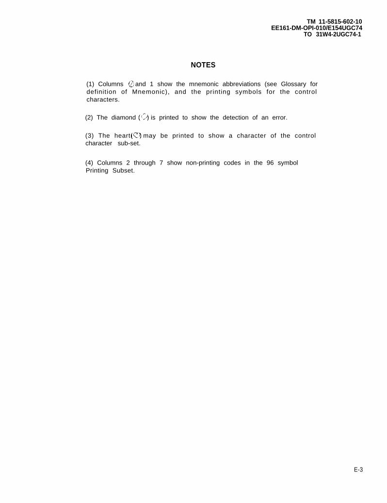
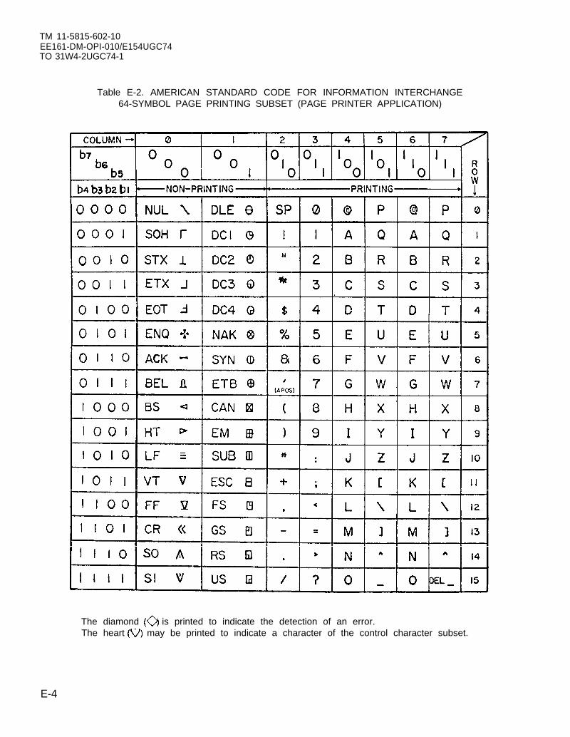
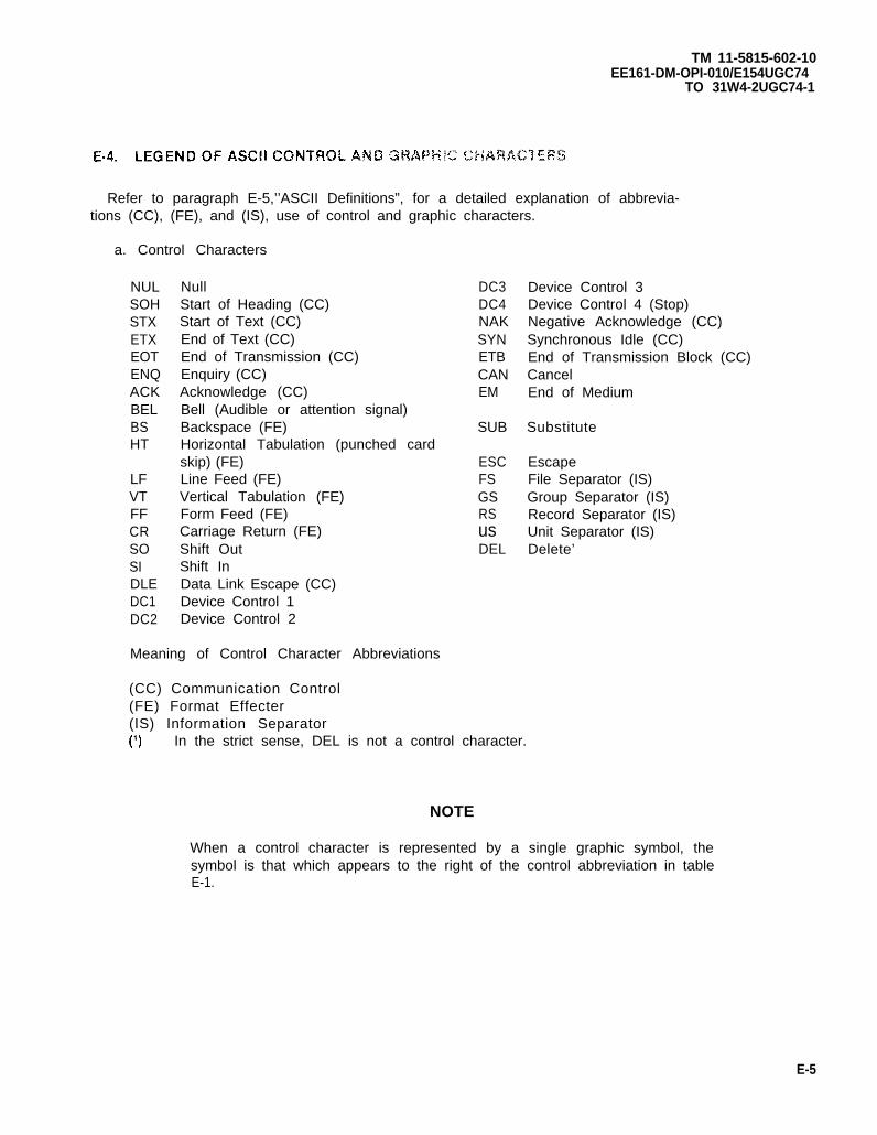
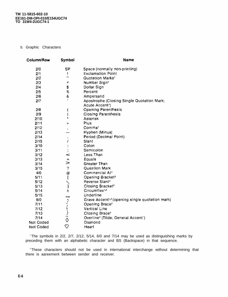

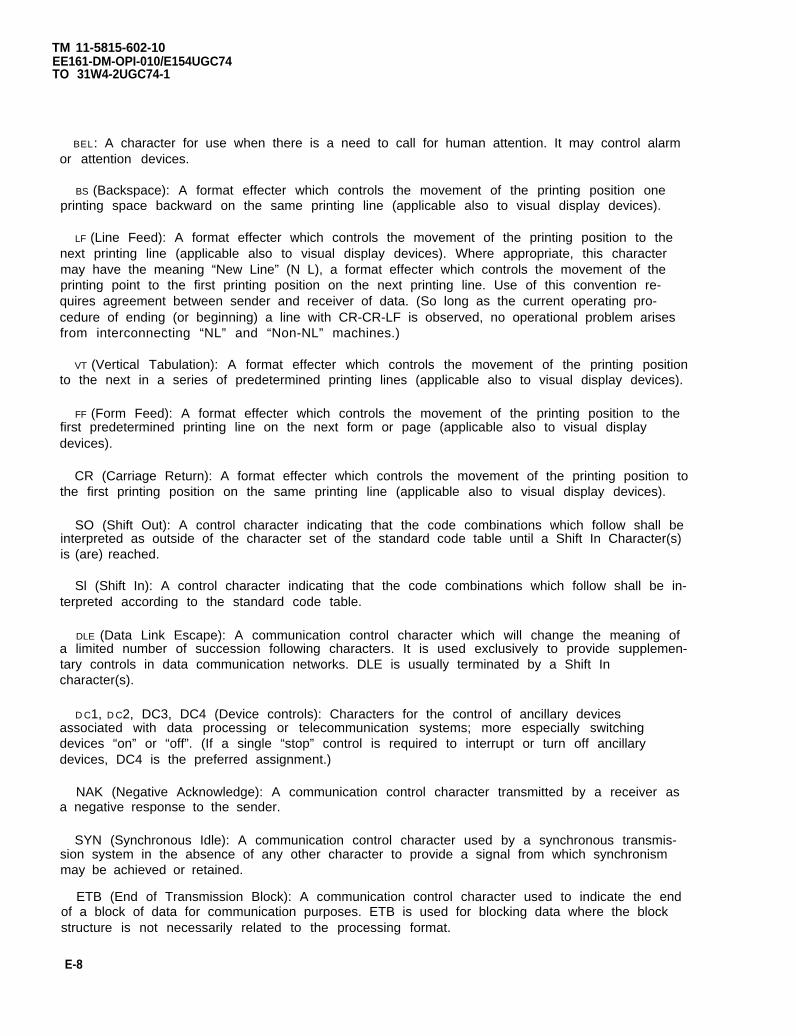
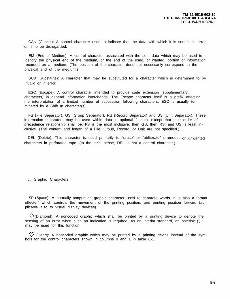

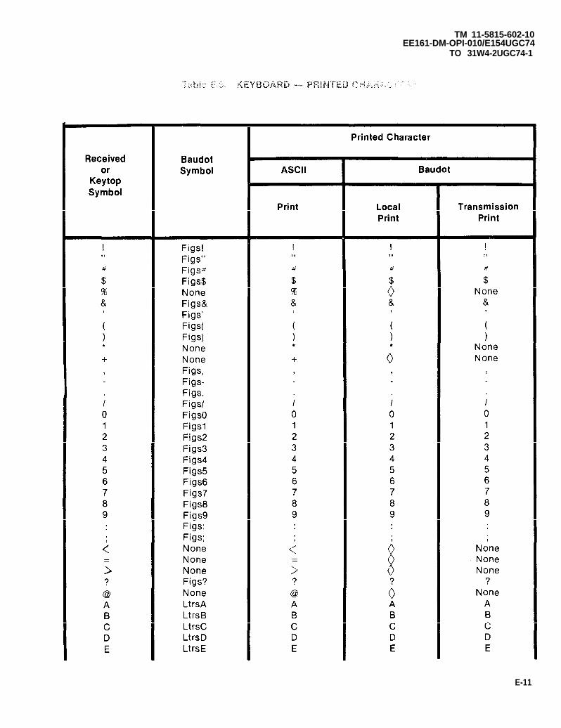
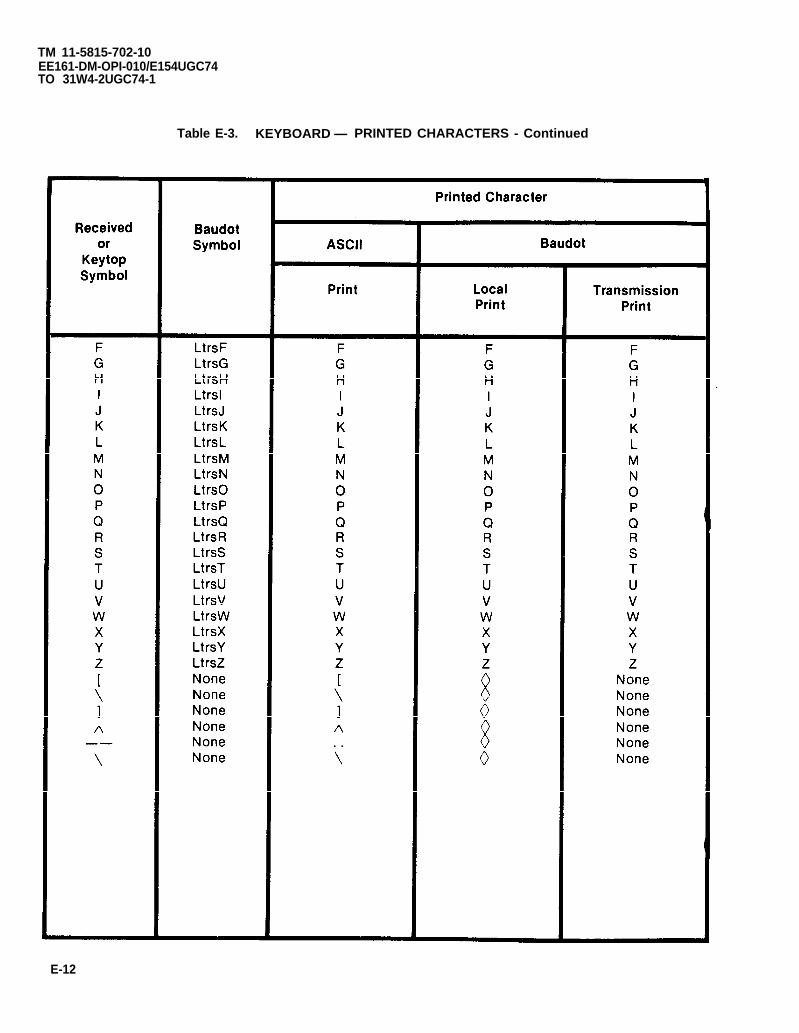
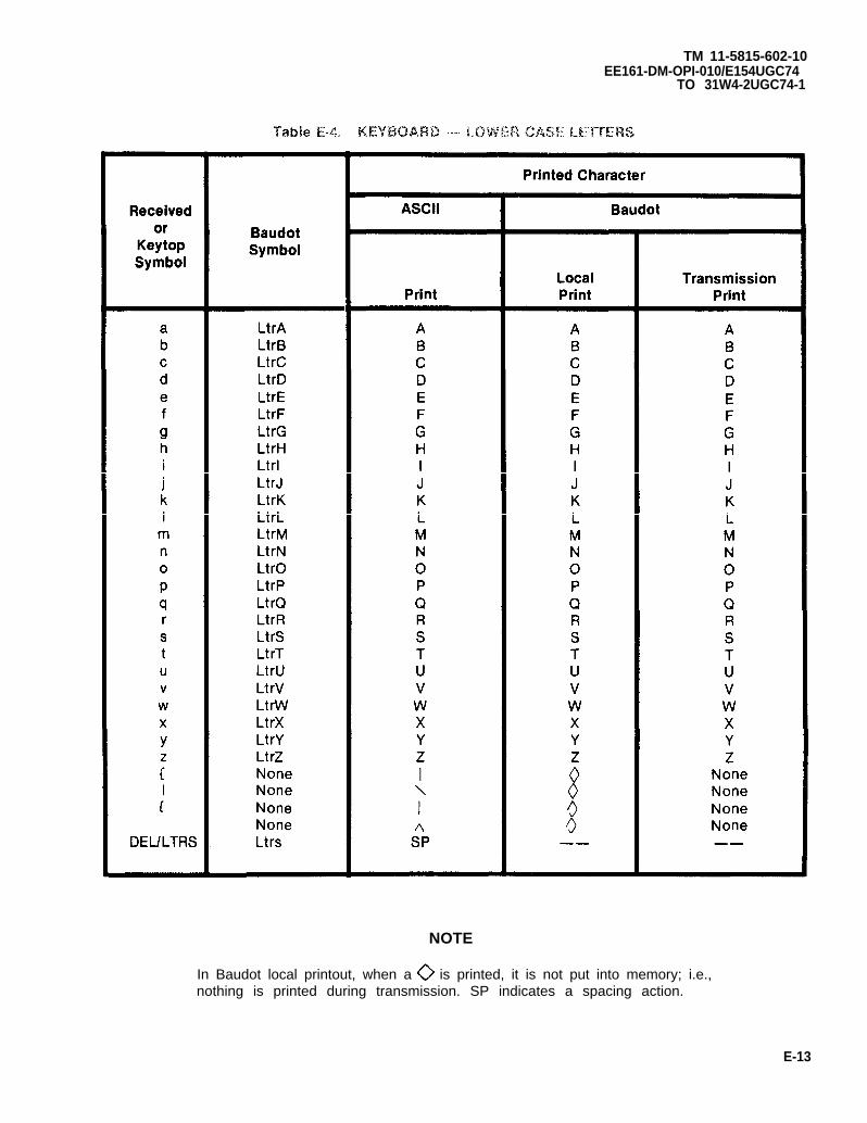
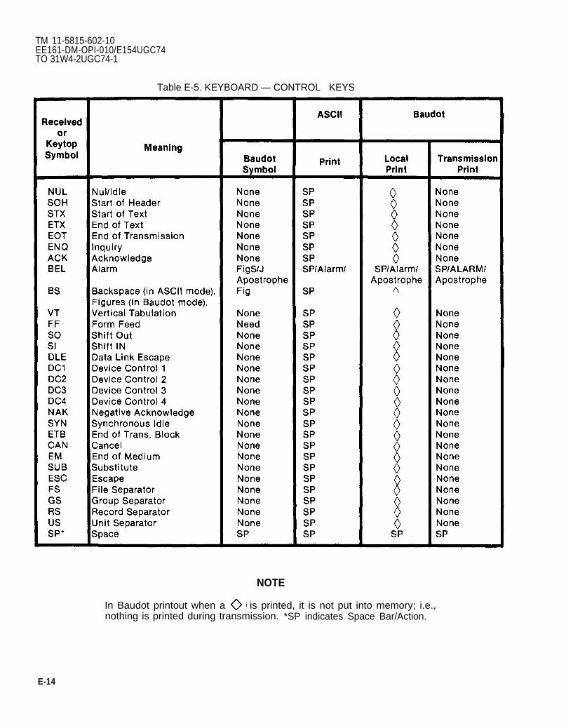
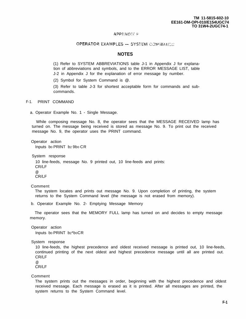
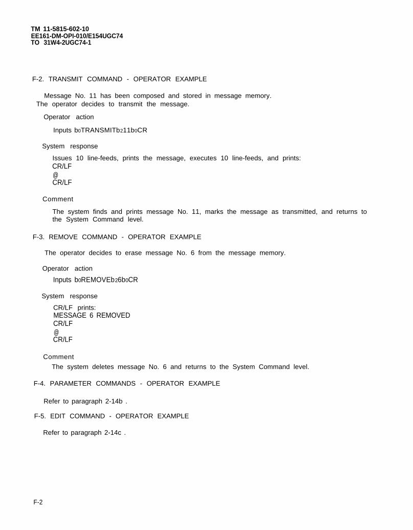
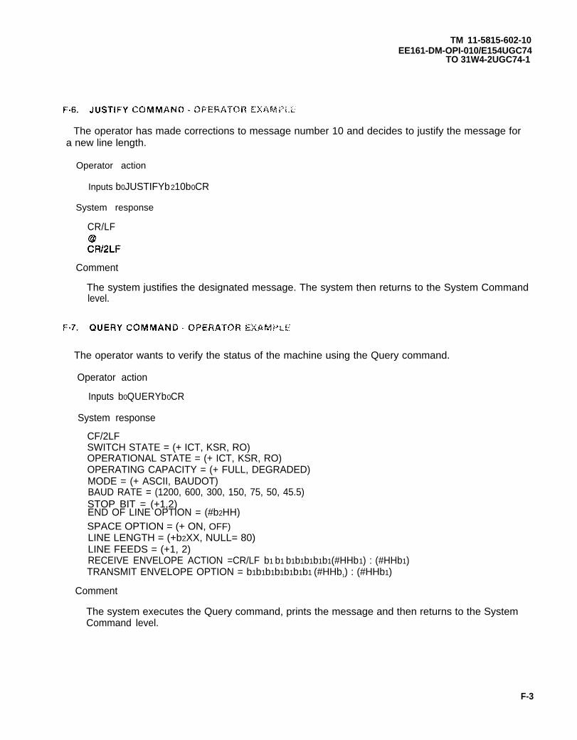
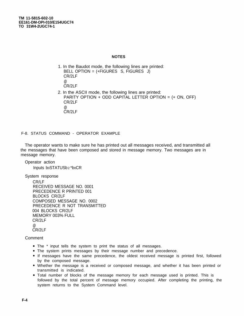
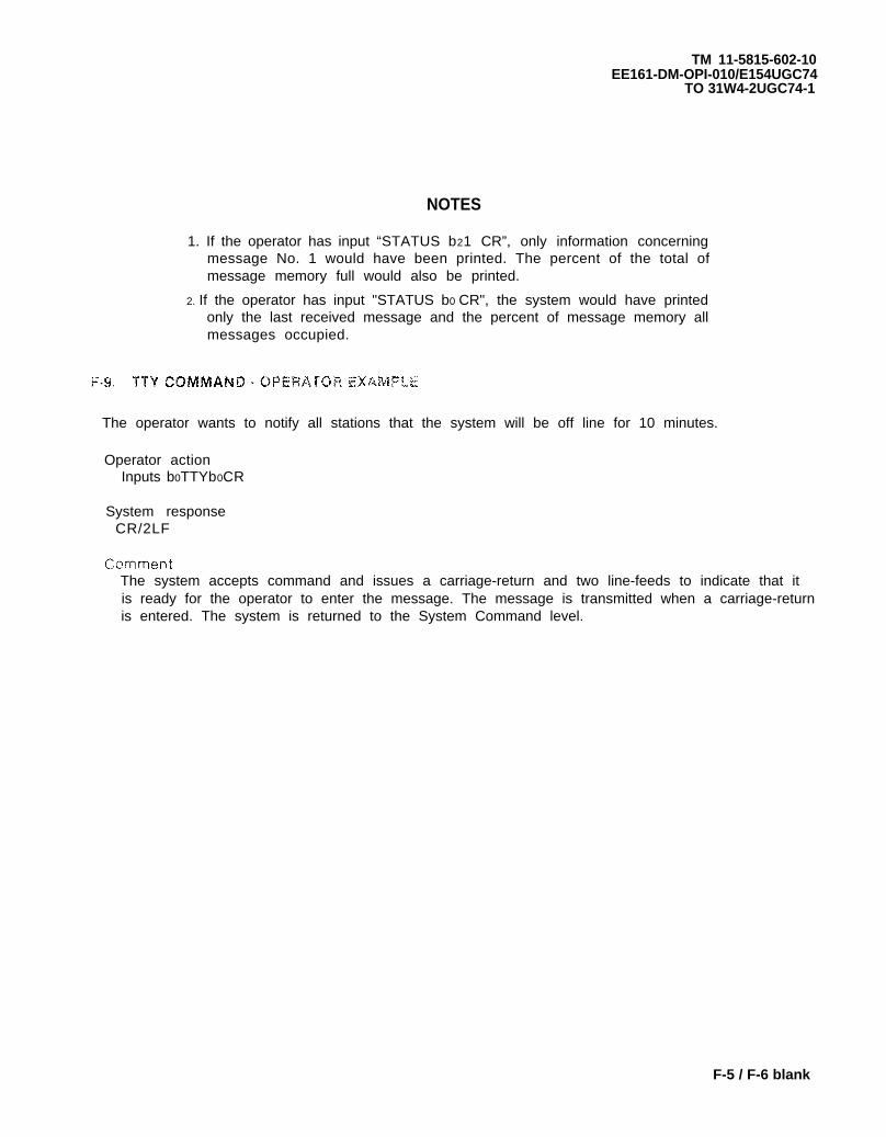
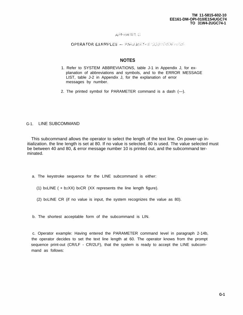
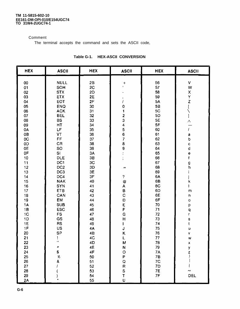
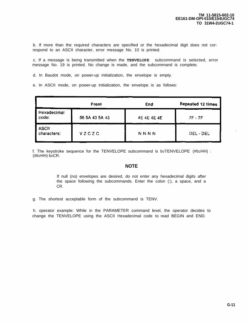
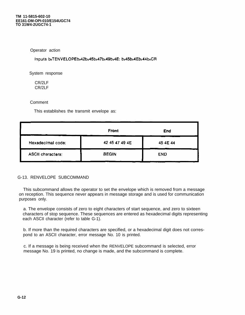
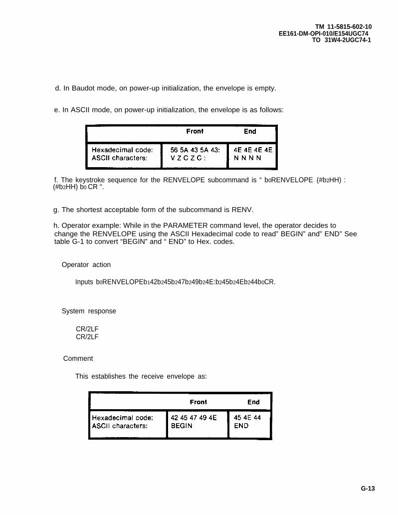


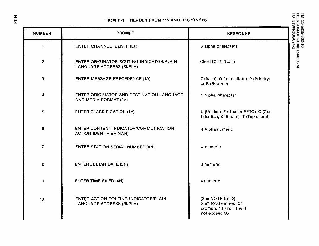
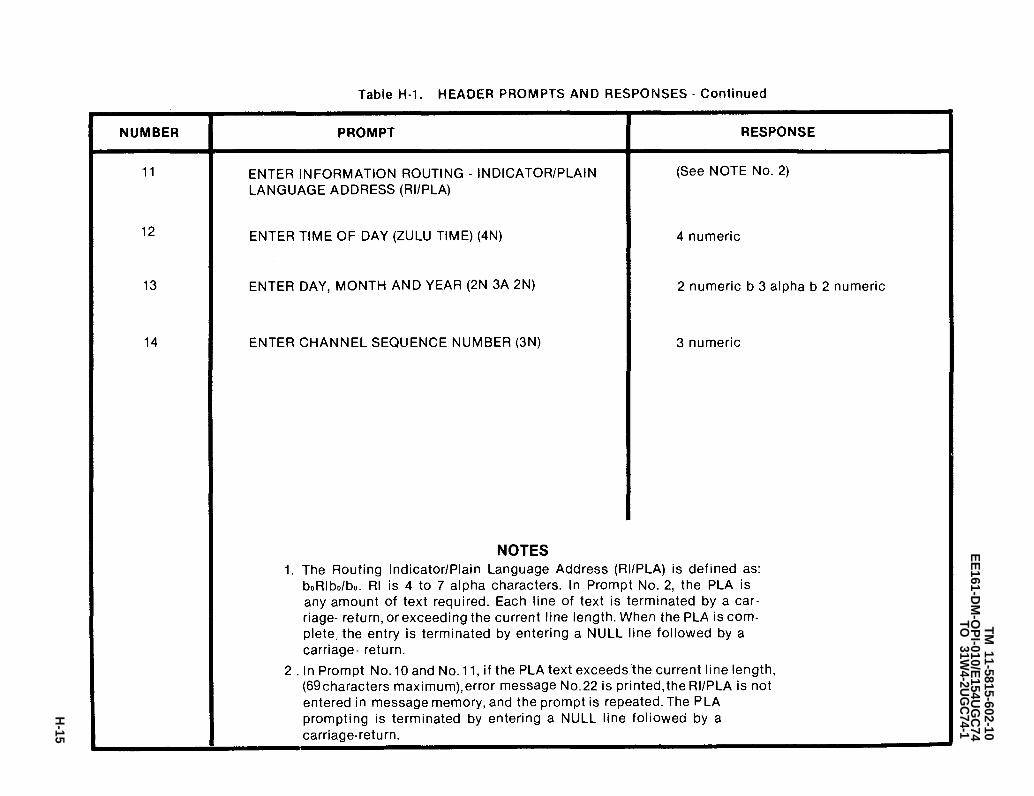
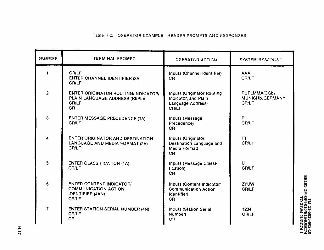

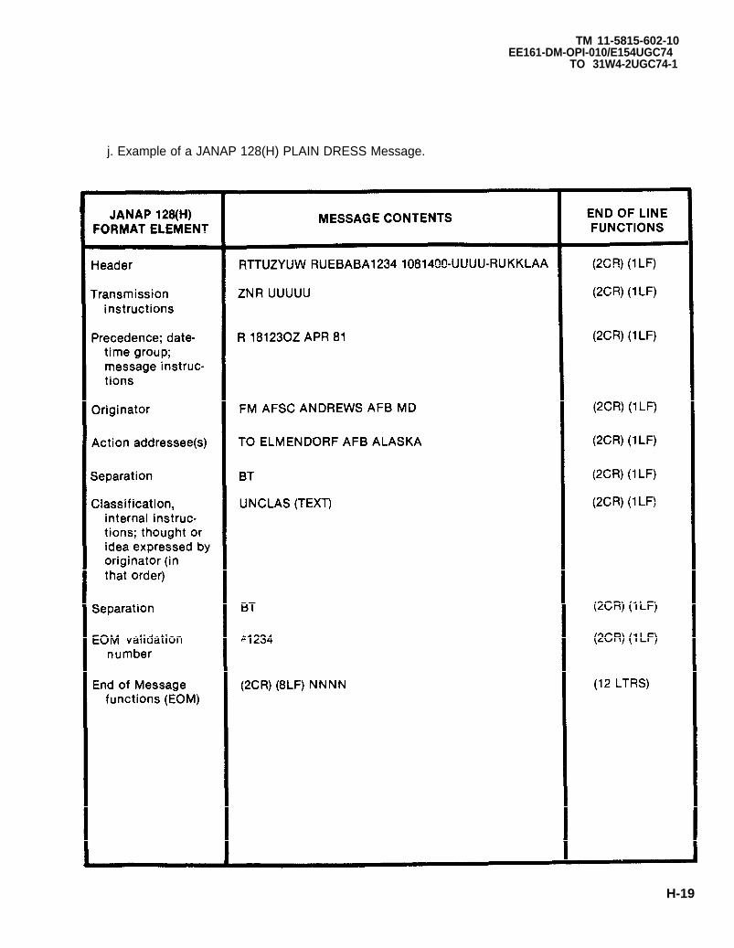

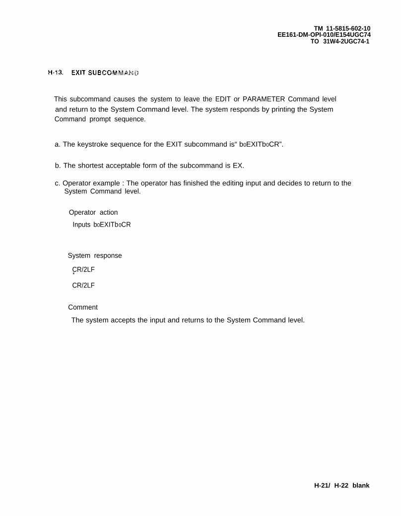
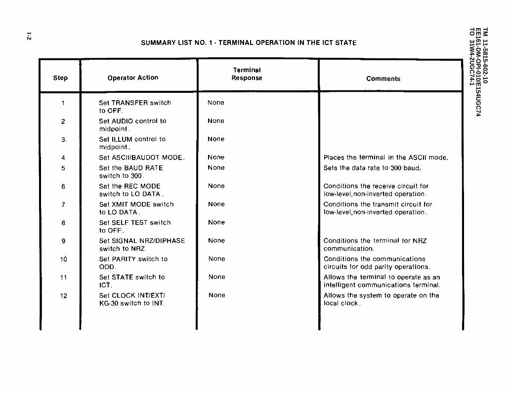
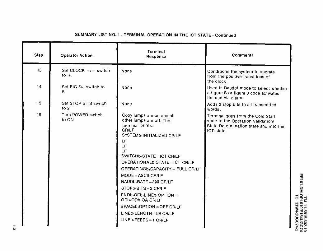
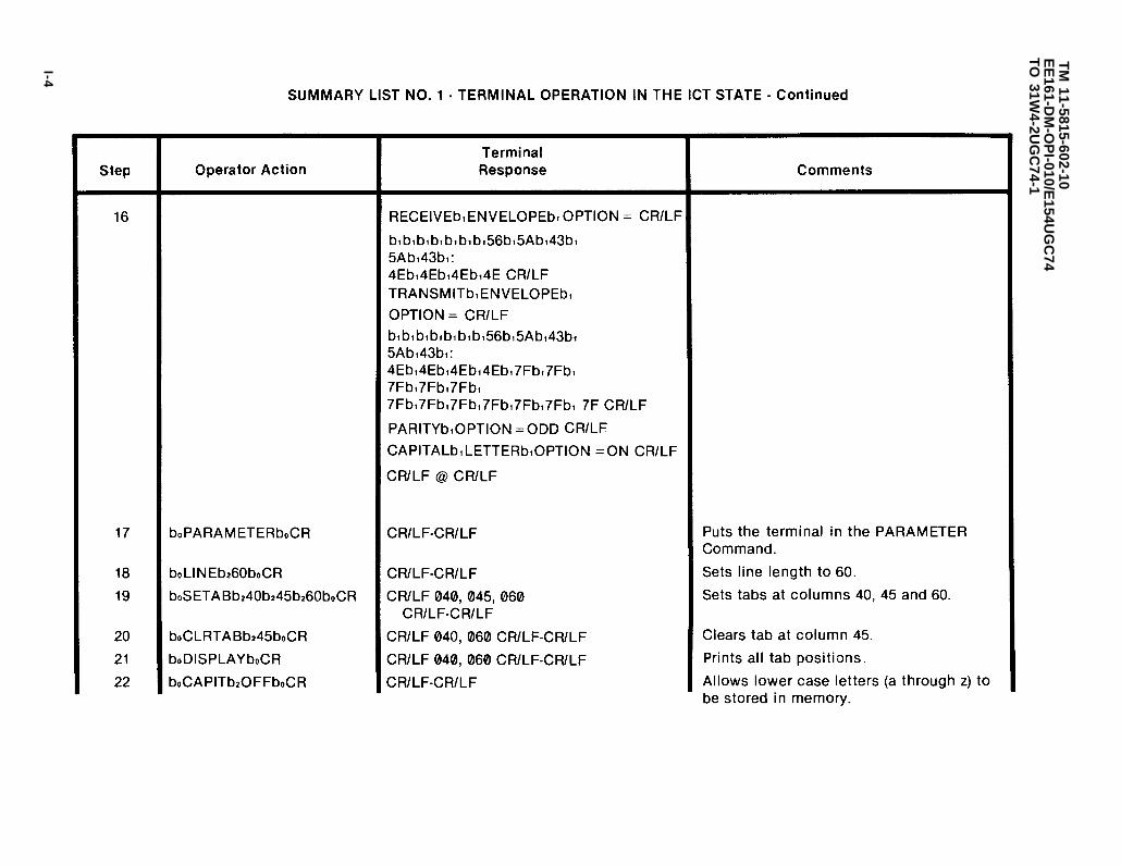
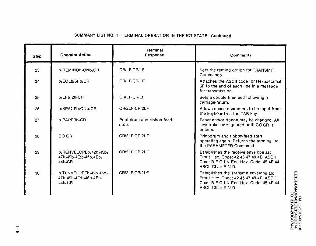
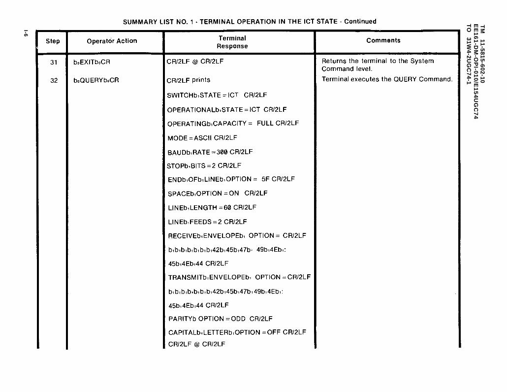
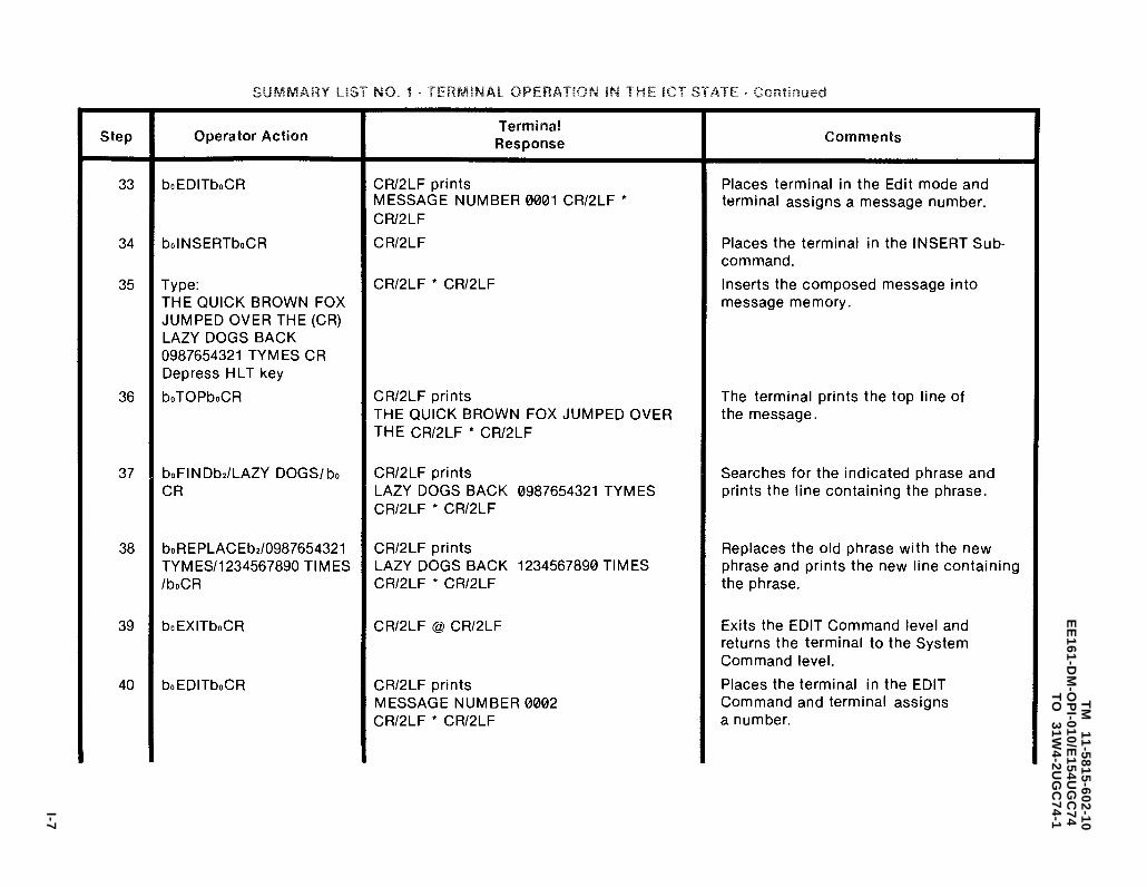
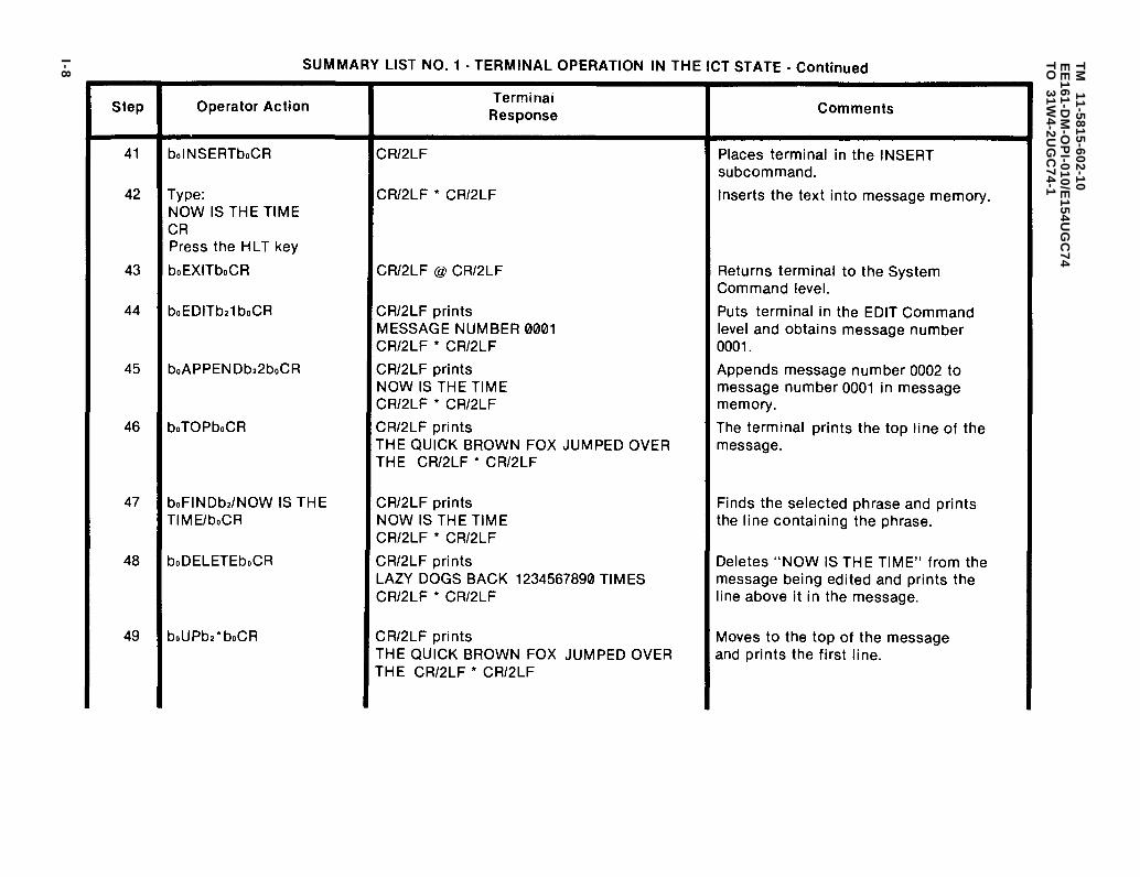
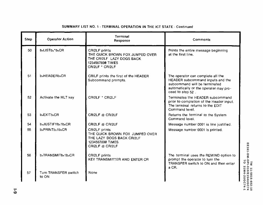
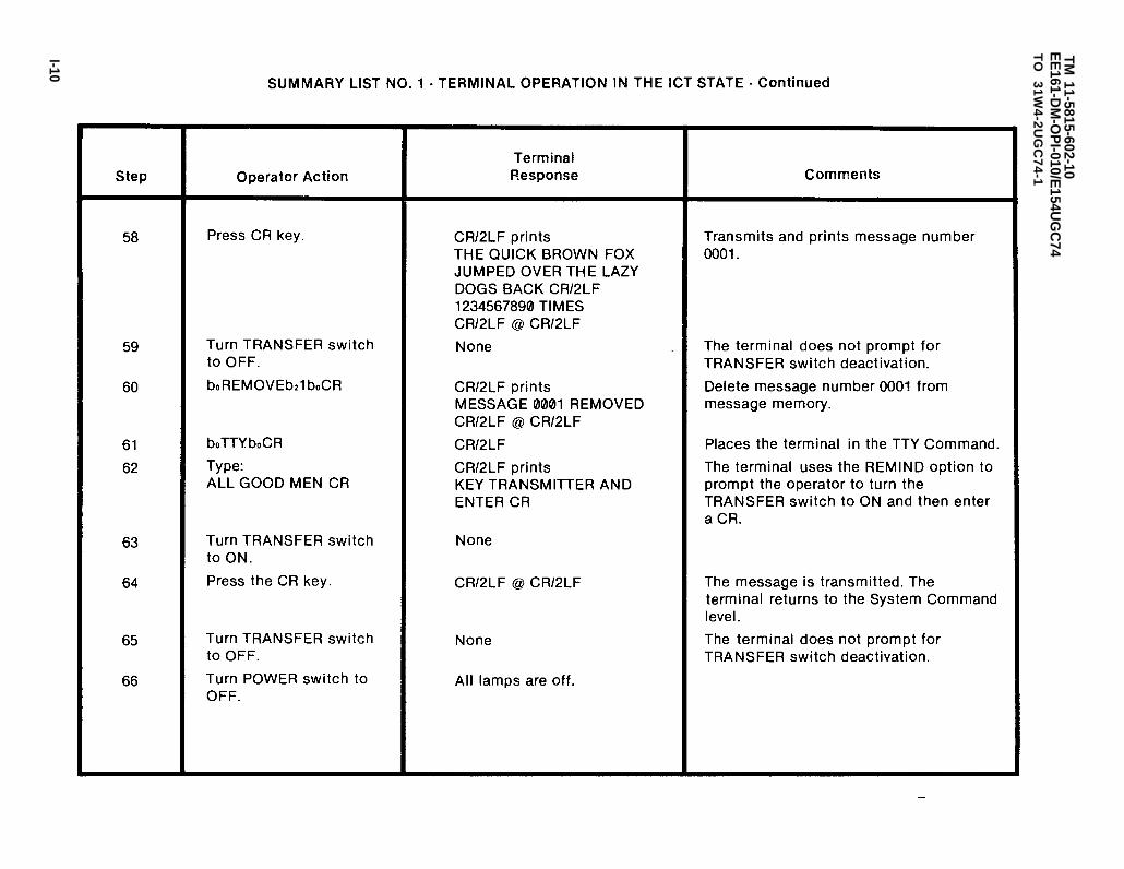
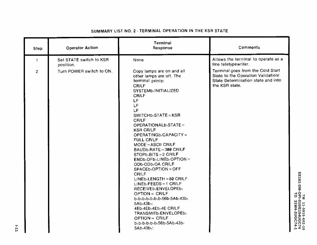
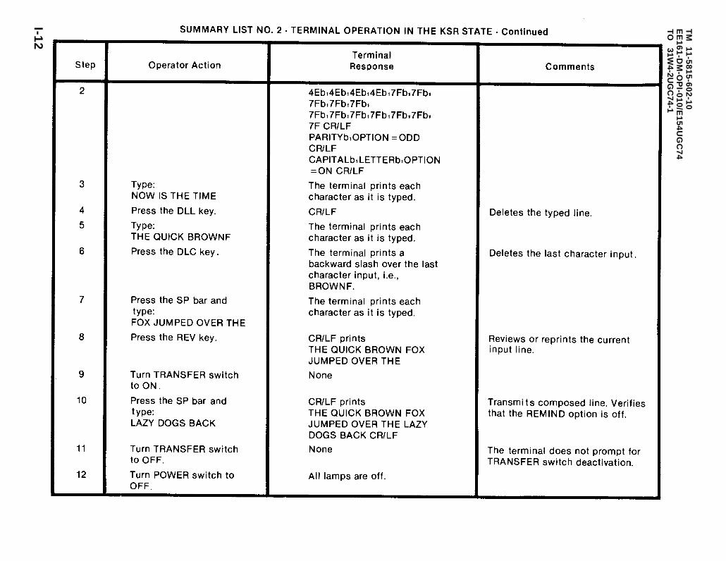
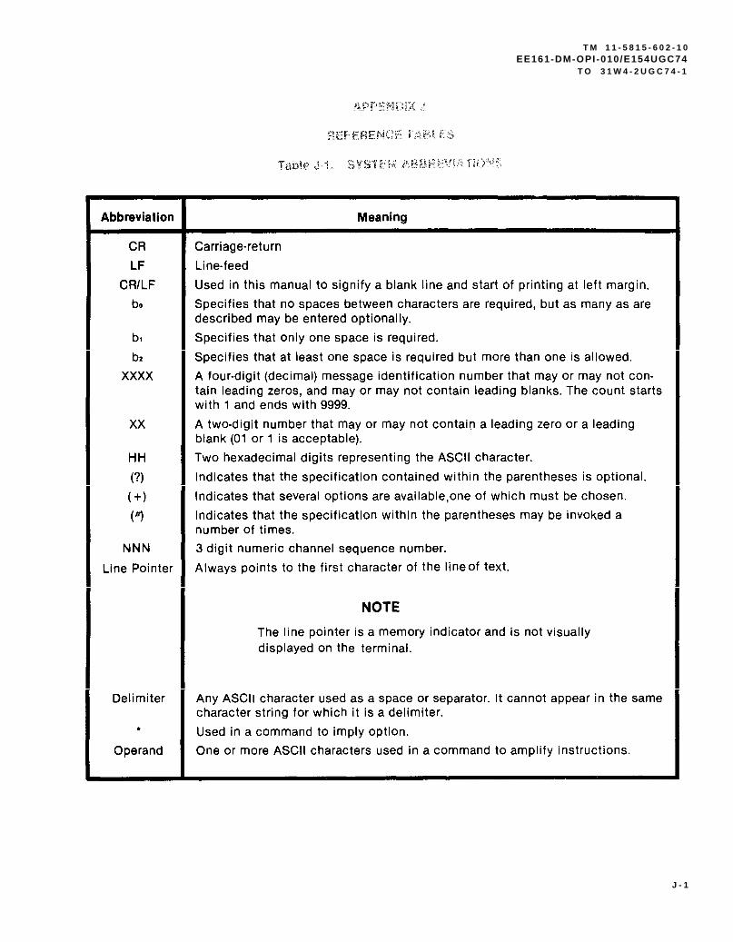
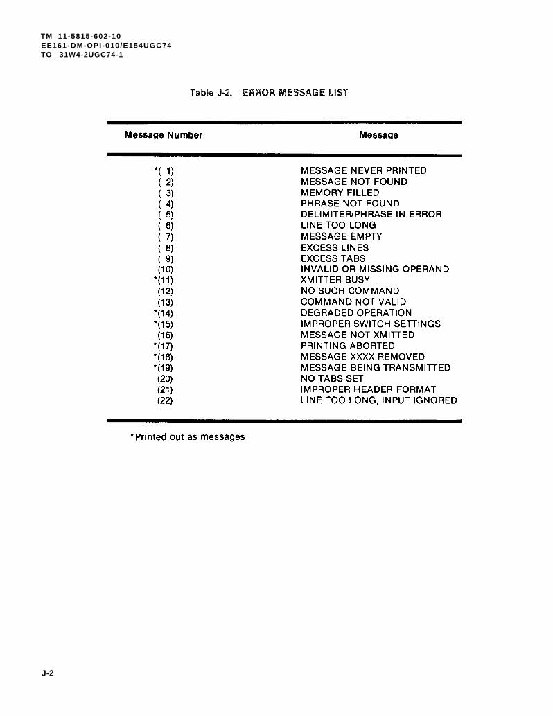
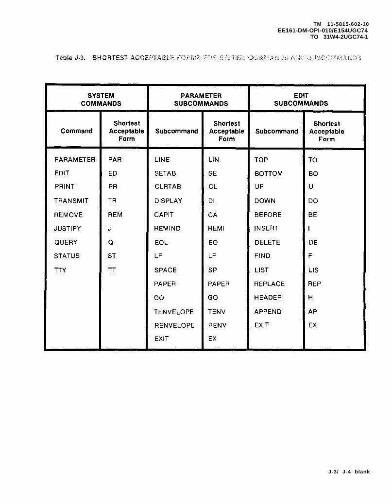
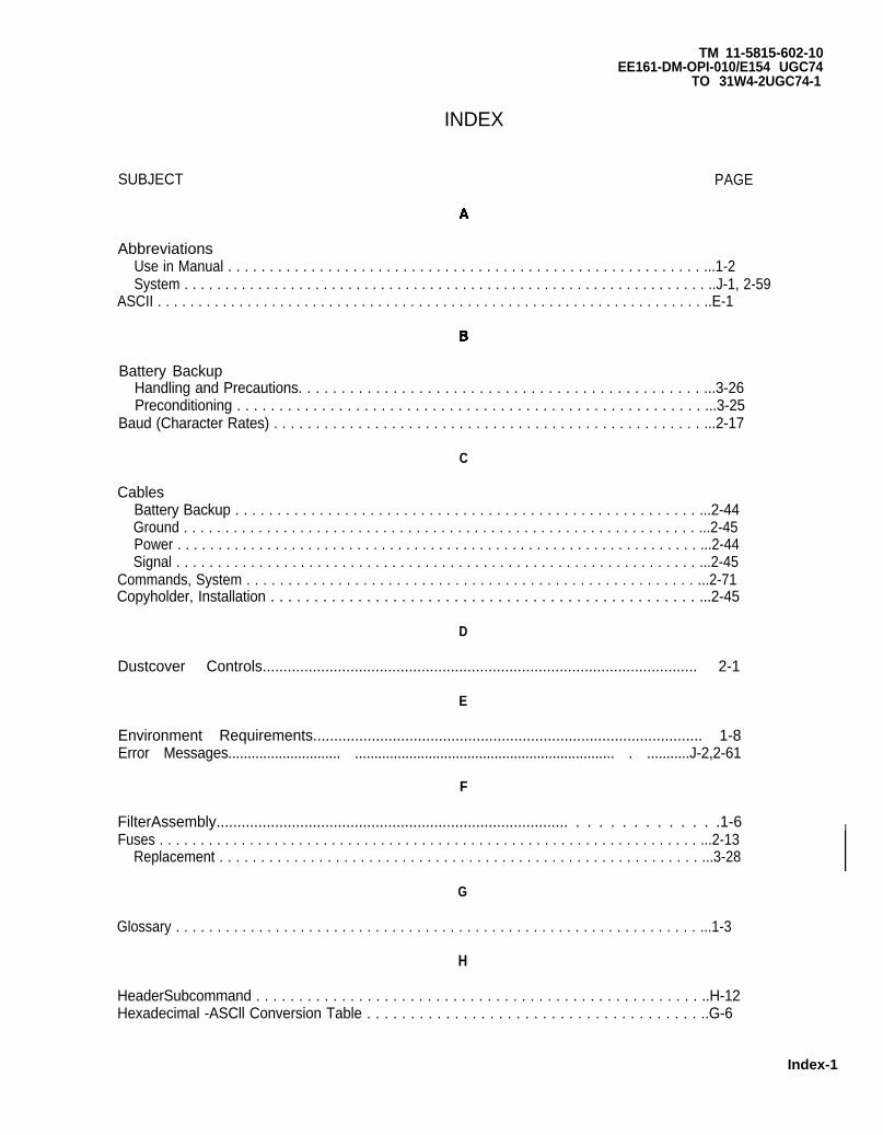
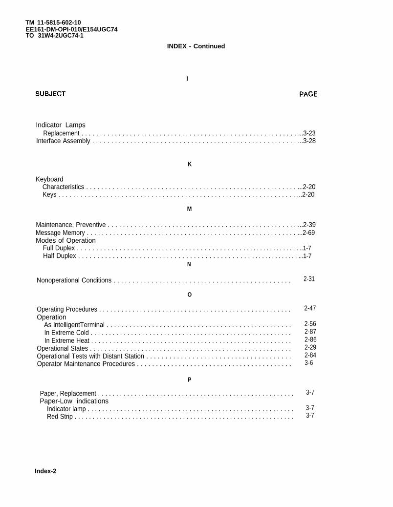
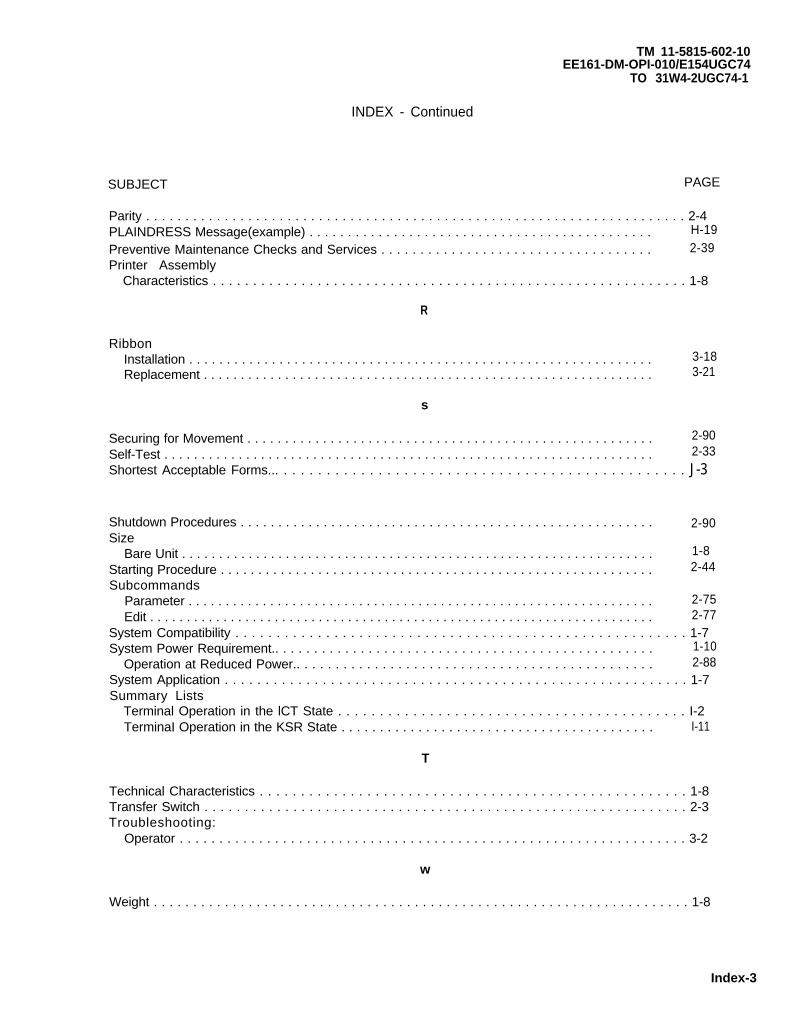

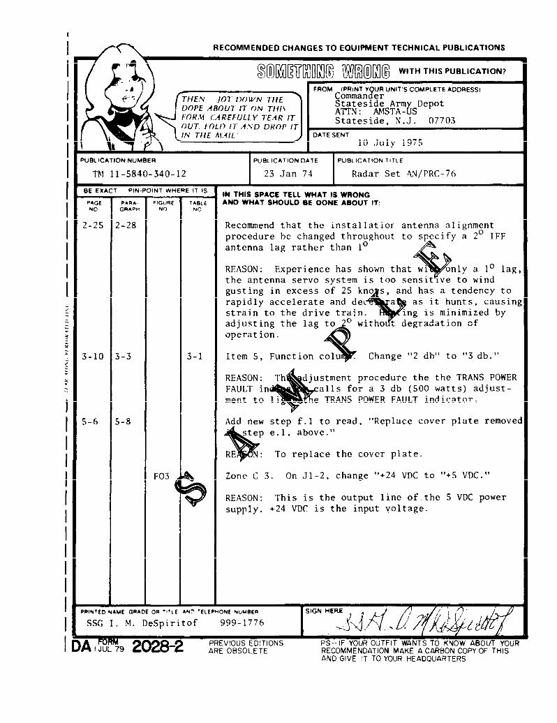
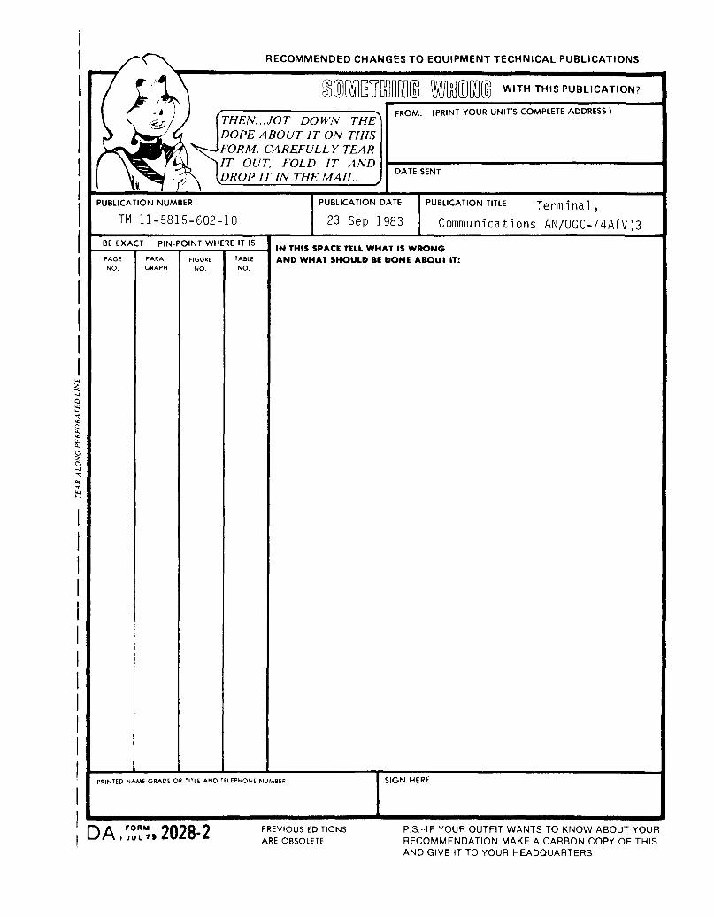
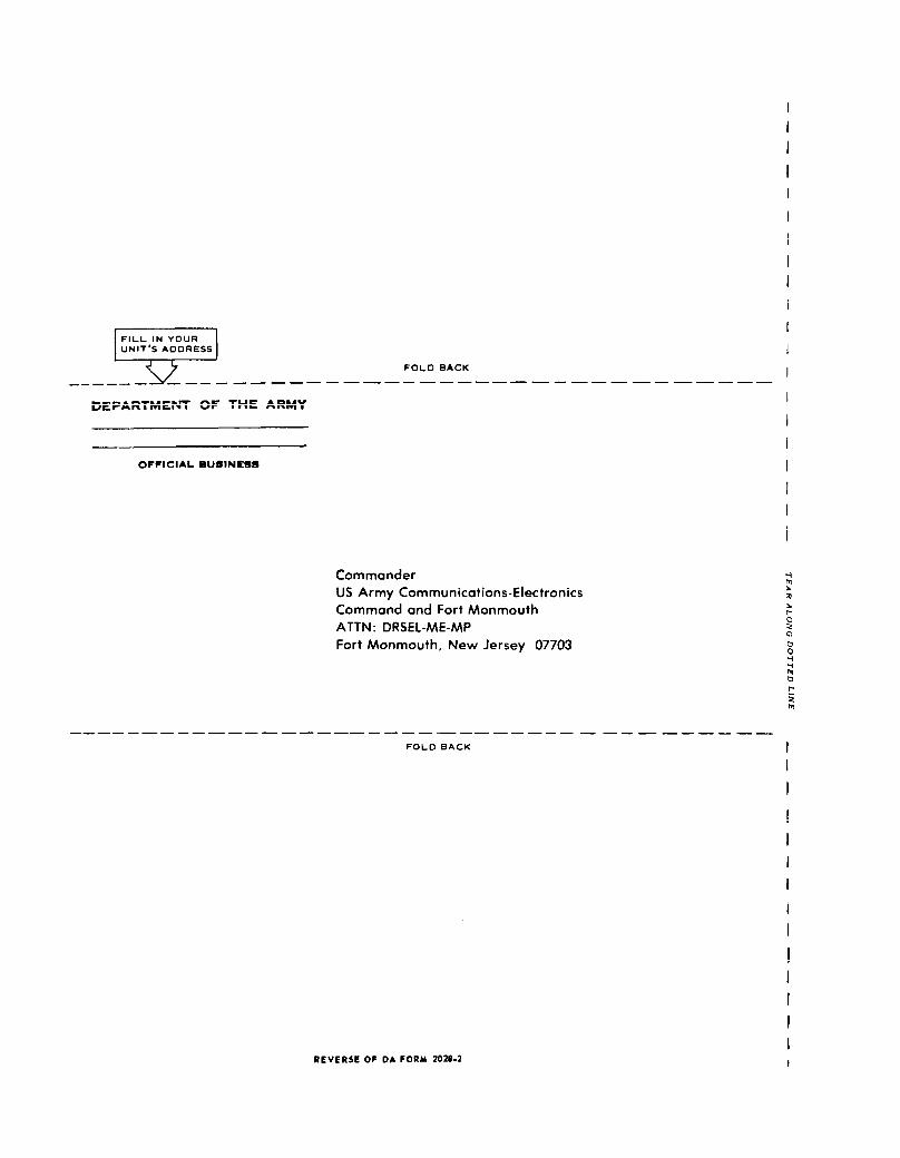
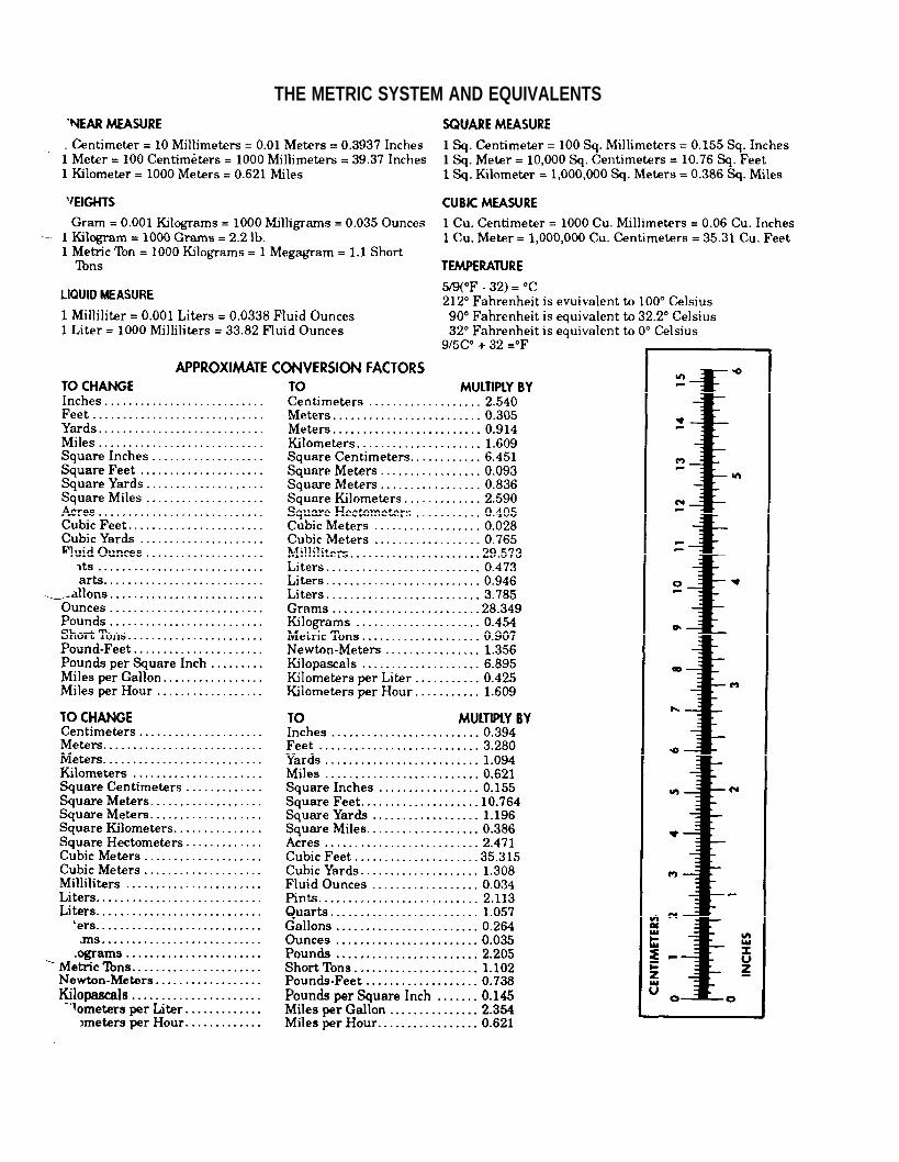


![Bill's Ham Radio Web Server [nj7p.info/nj7p.org] - OPERATOR ... 11-5815-332-15 15...RADIO TELETYPEWRITER SET AN/VSC-3A (NSN 5815-01-102-5916) TM 11-5815-332-15, 14 January 1971, is](https://static.documents.pub/doc/80x56/611e2198dbfb4036d0587b04/bills-ham-radio-web-server-nj7pinfonj7porg-operator-11-5815-332-15-15.jpg)


