DYNAMIC MODELING, DESIGN AND SIMULATION OF HYBRID POWER GENERATION SYSTEM M.T.A. Evo 1 , A. Mpanda 2 1 Universidade Federal de Minas Gerais, Belo Horizonte, Minas Gerais, Brazil, [email protected]2 Ècole Superieure d’I ngenieurs en Electronique et Electrotechniq ue d’Ámiens , Amiens, France AbstractNot only for environmental reason, or the likely shortage of so-called fossil fuels, drawing energy from renewable sources is a challenge that is present and necessary for the world today. The idea of decentralizing energy production makes easy the distribution to the consumer. Increasingly new technologies are discovered to enable the utilization of these countless sources. In this context, we develop a work that aims to model and through simulations, evaluate the operation of a hybrid system that uses the wind energy as primary source. Thus, by using the software MATLAB / Simulink, each element that composes the system is modeled by the equations that describe it. It is proposed a dynamic system composed of a wind turbine and a set of fuel cell to supplement power generation. Tanks of hydrogen with a flywheel are used to store energy in periods of low load to enable the use of this energy when the primary source is not enough. For this, the work shows the design of some electronic devices that perform control of the flow of energy to the load. Keywords: Wind power, Fuel cell, Hydrogen tanks, and Flywheel.1. INTRODUCTION A change of global scenery for using energy from renewable sources is inevitable. Renewable energy systems allow use of various types of sustainable resources (wind, water, sunshine,etc), reducing environmental impacts, increasing the supply of secure energy, and generate thousands of jobs in the long term. The wind energy is one of the renewable sources that have been explored more deeply, expanding its technologies and consequently, the opportunities in the use of that resource. However, due to seasonality in this type of generation, fluctuations in load curve, and even technical limitations, along with wind generation, become essential store the energy. Thus, it is possible obtain a better use of these renewables energy, and so minimize the "wasted" energy. We can divide the forms of energy storage into two groups: mechanical and electrical. The difference between them is that in the first, are used forces of mechanical nature to accomplish the storage. And the second, is used the surplus electricity generated to drive the storage mechanisms. The energy storage can be found at various locations within the grid, depending on the role as: Close to the generation, to provide power generating with high-quality transmission and reduce the costs ofconnection. Close to the load centers, to provide flexibility and ancillary services. As a solution for this energy storage problem, wind energy, after appropriate conversion, can be converted and then stored in the form of chemical energy of hydrogen. The conversion is made by the process of electrolysis of water, when, besides releasing heat, water molecules are separated, by the action of electric current, into hydrogen and oxygen atoms. The hydrogen then can be stored for later use in fuel cells (which recombine with oxygen from air with hydrogen to generate electricity) of three different forms: compressed and bottled liquefied and stored in bottles or insulated metal absorbed in hydrates. Furthermore, coupling wind turbines with electrolyzers has the potential to provide low-cost, environmentally friendly distributed generation of hydrogen in addition to electricity [1]. So, the stored hydrogen energy can be used by FC power plants during the low wind speed conditions [1]. The principal challenges to improving hydrogen storage technologies relate to increasing their efficiency, size, weight, capacity and, ultimately, their cost. Durability remains an issue, as does the development of unified international codes and safety standards to facilitate safe deployment of commercial technologies. To complement, and thus reduce costs of storing hydrogen, can be used other ways to store energy. As mentioned previously, energy can be stored not only as electricity, but also as mechanical energy. For this, flywheels are used, because with this element, the energy can be stored as rotational kinetic energy. Flywheel storage systems (FESS) are well adapted because they have high dynamics, long lifetime and good efficiency [2]. They constitute short-term storage systems, which are generally sufficient to improve the quality power. In case of fixed speed generator, the FESS must be connected on the AC grid. This energy storage system can mainly reduce the power variations due to the wind speed fluctuations. When the wind generator is coupled to a diesel generator in an isolated area, the energy storage system allows to reduce the fuel consumption and to increase the lifetime of the diesel engine [2]. Without the Flywheel, the FC system must supply all power demand, increasing the size and cost of the FC power plant. The work in question, seeks to model and simulate an isolated system of power generation.
DYNAMIC MODELING, DESIGN AND SIMULATION OF HYBRID POWER
GENERATION SYSTEM
M.T.A. Evo1, A. Mpanda2
1Universidade Federal de Minas Gerais, Belo Horizonte, Minas Gerais, Brazil, [email protected] 2Ècole Superieure d’Ingenieurs en Electronique et Electrotechnique d’Ámiens , Amiens, France
Abstract Not only for environmental reason, or thelikely shortage of so-called fossil fuels, drawing energyfrom renewable sources is a challenge that is present andnecessary for the world today. The idea of decentralizingenergy production makes easy the distribution to theconsumer. Increasingly new technologies are discovered toenable the utilization of these countless sources.
In this context, we develop a work that aims to modeland through simulations, evaluate the operation of a hybrid
system that uses the wind energy as primary source.Thus, by using the software MATLAB / Simulink, eachelement that composes the system is modeled by theequations that describe it.
It is proposed a dynamic system composed of a windturbine and a set of fuel cell to supplement powergeneration. Tanks of hydrogen with a flywheel are used tostore energy in periods of low load to enable the use of thisenergy when the primary source is not enough. For this, thework shows the design of some electronic devices thatperform control of the flow of energy to the load.
Keywords: Wind power, Fuel cell, Hydrogen tanks, and
Flywheel.
1. INTRODUCTION
A change of global scenery for using energy fromrenewable sources is inevitable. Renewable energy systemsallow use of various types of sustainable resources (wind,water, sunshine,etc), reducing environmental impacts,increasing the supply of secure energy, and generatethousands of jobs in the long term.
The wind energy is one of the renewable sources thathave been explored more deeply, expanding its technologiesand consequently, the opportunities in the use of that
resource.However, due to seasonality in this type of generation,
fluctuations in load curve, and even technical limitations,along with wind generation, become essential store theenergy. Thus, it is possible obtain a better use of theserenewables energy, and so minimize the "wasted" energy.
We can divide the forms of energy storage into twogroups: mechanical and electrical. The difference betweenthem is that in the first, are used forces of mechanical natureto accomplish the storage. And the second, is used thesurplus electricity generated to drive the storagemechanisms.
The energy storage can be found at various locations
within the grid, depending on the role as:
Close to the generation, to provide power generatingwith high-quality transmission and reduce the costs of connection.
Close to the load centers, to provide flexibility andancillary services.
As a solution for this energy storage problem, windenergy, after appropriate conversion, can be converted andthen stored in the form of chemical energy of hydrogen. Theconversion is made by the process of electrolysis of water,when, besides releasing heat, water molecules areseparated, by the action of electric current, into hydrogenand oxygen atoms. The hydrogen then can be stored for lateruse in fuel cells (which recombine with oxygen from airwith hydrogen to generate electricity) of three differentforms: compressed and bottled liquefied and stored inbottles or insulated metal absorbed in hydrates. Furthermore,coupling wind turbines with electrolyzers has the potentialto provide low-cost, environmentally friendly distributedgeneration of hydrogen in addition to electricity [1]. So, thestored hydrogen energy can be used by FC power plants
during the low wind speed conditions [1].The principal challenges to improving hydrogen storagetechnologies relate to increasing their efficiency, size,weight, capacity and, ultimately, their cost. Durabilityremains an issue, as does the development of unifiedinternational codes and safety standards to facilitate safedeployment of commercial technologies.
To complement, and thus reduce costs of storinghydrogen, can be used other ways to store energy. Asmentioned previously, energy can be stored not only aselectricity, but also as mechanical energy. For this,flywheels are used, because with this element, the energycan be stored as rotational kinetic energy. Flywheel storage
systems (FESS) are well adapted because they have highdynamics, long lifetime and good efficiency [2]. Theyconstitute short-term storage systems, which are generallysufficient to improve the quality power.
In case of fixed speed generator, the FESS must beconnected on the AC grid. This energy storage system canmainly reduce the power variations due to the wind speedfluctuations. When the wind generator is coupled to a dieselgenerator in an isolated area, the energy storage systemallows to reduce the fuel consumption and to increase thelifetime of the diesel engine [2]. Without the Flywheel, theFC system must supply all power demand, increasing thesize and cost of the FC power plant.
The work in question, seeks to model and simulate anisolated system of power generation.
The system basically consists of a wind generator, as themain generator, a fuel cell system and an energy storagesystem consisting of a hydrogen tank and a flywheel.
From the results obtained by simulation will be possibleto conduct a study on the importance of the storage systembefore the changes in resources, that is, an analysis will be
conducted on the influence of random variation of windspeed and, as the proposed solution storage can allow theproper functioning of the entire system.
2. DEVELOPED SYSTEM
In this section will be doing a study of each part of thewhole system. The system consists of a wind turbinecoupled in an induction generator, a double bridge rectifierwith PI controlling firing angle, a fuel cell, composed with awater electrolyze and hydrogen storage tank, coupled in adc/dc buck converter, a flywheel coupled in an inductiongenerator for storage energy in form of energy kinetic, two
dc/ac IGBT inverters and a three-windings couplingtransformer located at the load side. The system is show inthe figure (2.1).
Figure 2.1 – Block diagram of the system
2.1. Wind turbine and induction generator
The wind turbine is modeled from the variation of theoutput power mechanical with the wind speed. And theinduction generator is modeled from dynamics equationswhere is adopted the reference normed Park (outwardcurrents positive and direct axis taken 90 ° ahead of thequadrature axis) working in a flow oriented to axis “d” (vds = 0). The parameters used in the mathematical modeling areas follows.
Cp(λ,θ) Performance coefficient of the turbineρ Air density [kg/m3]A Turbine swept area [m2]vwind Wind speed [m/s]λ Tip speed ratio of the rotor blade
tip speed to wind speedθ Blade pitch angle []vds, ids, E’d Direct components of Park (stator voltage
[V], current [A] and the EFM [V])vqs, iqs, E’q Quadrature components of ParkRs, Rr Equivalents resistances of stator/rotor [Ω] Ls, Lr Equivalents inductances of stator/rotor [H]L
mMagnetizing inductance [H]
ws wr Electrical frequency, Rotor speed [rad/s]Tm, Te Mechanical and electrical torque [N.m]
The relation of Cp, λ and θ is is given by [1]:
Where,
The expression of the mechanical power is given by [3,4, 5]:
(2.3)
Taking into account the transient rotor, the equations of a cage induction machine are as follows:
(2.4)
(2.5)
(2.6)
(2.7)
Where,
(2.8)
(2.9)
Equations (2.4) to (2.7) are of a cage inductiongenerator. For close the loop, must be added the equation of the moving masses given below:
(2.10)
The simulink model of the wind turbine coupled toinduction generator is shown in figure (2.2).
Figure 2.2 – Simulink model of wind turbine and IM.
A fuel cell can be defined as a device electrochemicalthat transforms the chemical energy into electrical energy(and some heat) since there is a fuel and oxidizer supplied tohim. The fuel is hydrogen or a compound that has in its
constitution and the oxidant is oxygen.The operating principle of a fuel cell is shown in thediagram below.
Figure 2.3 - Diagram of a fuel cell
The oxidation of hydrogen and the reduction of oxygenare described in the equations below:
(2.11)
(2.12)
Resulting in a global reaction:
(2.13)
A fuel cell consists of a series association of cells fuelunit. Due to the fact of each individual cell produces onlyapproximately 0.6 V. Thus, it's possible obtain a fuel cellwith the voltage value required for an application. Forincrease the current of a fuel cell, it’s needed an associationin parallel of cells unit.
A Fuel Cell model can be built using the relationshipbetween output voltage and partial pressure of hydrogen,oxygen and water.
The parameters used in the mathematical modeling areas follows.
qH2
in
Hydrogen input flow [kmol (s)-1
]pH2
Hydrogen partial pressure [atm]
Kan Anode valve constant [√(kmol.kg) (atm.s)-1]MH2
Figure 2.4 - Dynamic model of the Fuel Cell system.
For operating the FC in different levels of output power,is necessary to vary the flow of input hydrogen. The amountof hydrogen available is given by [6]:
(2.23)
So, it’s possible control the amount of hydrogen taking afeedback of the demand current.
The power demand requirement of the FC is translatedinto a current demand input by dividing with the stackoutput voltage:
(2.24)
A block diagram of the control system of hydrogen inputfor the fuel cell is shown in figure (2.5).
Figure 2Error! No text of specified style in document. .5 -Fuel Cell control system architecture
2.3. Producing hydrogen
Hydrogen can be obtained from several differentsources. These sources can be separated into two categories:
fossil resources (natural gas and coal) and renewableresources (biomass and water). To produce hydrogen,various kinds of technology are available, and use of manydifferent processes such as chemical, biological, electrolytic,proteolytic chemical and thermal.
However, the production of hydrogen on a largescale is a long term process as shown in figure (2.6).
Figure 2.6 - Main hydrogen pathways: the long termperspective
One way to obtain hydrogen is by electrolysis of water.On this way, the hydrogen can be obtained “cleanly”, i.e.with a minimal environmental impact, due to the fact thatthe hydrogen is met from renewable energy sources, and so,has fewer air pollution impacts than fossil-fuel source of
hydrogen.The high price to obtain hydrogen may be the mostaggravating factor in its adoption as fuel.
The global equation for the water electrolysis is shownbelow:
(2.25)
The parameters used in the mathematical modeling of the electrolyser are as follows.
nH2 Hydrogen production ratenF Faraday efficiencynC Number of electrolyzer cells in seriesie Electrolyzer current [A]F Faraday constant [C (kmol)-1]
According to Faraday’s law, hydrogen production rate of an electrolyzer cell is directly proportional to the electricalcurrent in the equivalent electrolyzer circuit [6].
(2.26)
Where,
( ⁄ ⁄ ) (2.27)
The Simulink model of the dynamic model of theElectrolyzer system is shown in figure (2.7).
The hydrogen has a low volume density of energy. Thatis, the hydrogen has a small amount of energy for a givenvolume. Thus, it becomes necessary to store large quantitiesof hydrogen, which is still a source of great challenges.
The hydrogen can be stored in liquid, solid or gaseousstate. However, it is known that one gram of hydrogen gasoccupies 11 liters at atmospheric pressure. Thus, to becomeviable, it is necessary to keep the gas in pressure vessels andthus maintain the pressure in the gas hundreds of timesgreater than atmospheric. In liquid form, hydrogen can bestored at extremely low temperatures.
The hydrogen storage tank was modeled to only countthe amount of stored hydrogen versus time.
That is, the tank modeled just shows how muchhydrogen is being produced but not used by the fuel cell.
Figure (2.8) shows the block diagram representing thetank.
Figure 2.8 - Block diagram representing the dynamic of thetank
2.5. Flywheel
In a traditional manner, flywheel is a mechanical devicethat has a high moment of inertia used to store rotationalenergy. They can tolerate sudden changes in angular
velocity, thus they are used to regulate rotation of the shaftwhen a fluctuating torque is exerted. Therefore, for this kindof application, flywheels were constructed like a wheel or adisk with a fixed axis, so that rotation is only in one axis.
Due to the fact with the huge advances in electronicdevices for power systems, now, flywheels are part of ingenious constructions, which are capable of transferringthe energy to and from the flywheel. This is accomplishedwith an electrical machine that is used for energyconversion, and can function either as a motor or generatordepending on the load angle (phase angle). When acting asmotor, electric energy supplied to the stator winding isconverted to torque and applied to the rotor, causing it to
spin faster and gain kinetic energy. In generator modekinetic energy stored in the rotor applies a torque, which isconverted to electric energy. So, it can be used in powerplants or electric power industrial plants, being used to storeenergy "left over", ie, out of peak hours, to be used later andcan be used to store energy for hybrid cars too. Figure (2.9)shows the basic layout of a flywheel energy storage system[7].
Figure 2Error! No text of specified style in document. .9 -Basic layout of a flywheel energy storage system
The flywheel has a high efficiency, approximately 90%,and a high power density too. It has a short recharge timeand the state of charge can easily be measured since it isrelated to the rotational speed [8]. Furthermore, alsopresents a low environmental cost, since it does not use fuel.
It has a great useful life that is almost independent of thedepth of the charge and discharge cycle. Flywheels have alow maintenance costs and, unlike battery storage systems,flywheels can operate equally well on shallow and deepdischarges [8].
On the other hand, the flywheel has high initials costsand little resistance to mechanical shock.
The parameters used in the mathematical modeling of the Flywheel are as follows.
EK Kinetic energy of the rotor [J]I Moment of inertia of the rotor [kg.m2]w Angular velocity [rad (s)-1]
m Mass [kg]r Radius of the disc [m]T Mechanical torque [N.m]EC Capacitor stored energyC Capacitance [F]Vf , Vi, VC Final, initial and instantaneous voltage of
the capacitorIC Current through a capacitor
The energy is stored as kinetic energy of the rotor, givenby equation below [9]:
(2.28)
Where,
(2.29)
As can be seen in equation (2.28) and (2.29), the kineticenergy stored is proportional to the mass and the square of the radius and velocity of the flywheel. So, the mostefficient way to increase the stored energy is to speed up theflywheel.
The mechanical torque in a flywheel can be describedby:
A flywheel can be modeled as a capacitor charging witha DC current. The stored energy and current through acapacitor can be described by:
(2.31)
(2.32)
Comparing equations (2.28) and (2.30) with equations(2.31) and (2.32) it is noticed that the flywheel is describedby the same dynamic charging / discharging of a capacitor.With the torque represented by the current of the capacitor,the moment of inertia represented like a capacitance C, andthe angular velocity as a voltage. While the inverter is thegenerator coupled to the flywheel.
3. POWER CONTROLLING
The control of the energy generated is done to explorethe full potential of the available wind.
To achieve this purpose, the system is designed to workas follows: when the wind is sufficient to generate an energythat is capable of supplying the load and the electrolyzer,then the wind turbine feeds the electrolyzer and the load. So,the electrolyzer can continues to produce hydrogen. In asecond situation, if the wind speed is insufficient to allowthe turbine to generate energy and meet the demand of theload, the hydrogen tank feeds the fuel cell, which starts togenerate power as well, and help the system meet all theenergy demanded. On the other hand, if the fuel cell reachesa maximum energy that it can deliver, the excess of energyis supplied by the flywheel.
To achieve the proposed control, the power controlsystem is based on two buses of constant tension in additionto a double bridge rectifier with PI controlling firing angle, adc/dc buck converter, two dc/ac IGBT inverters and a three-windings coupling transformer.
3.1. Double bridge rectifier
Due to variations in wind speed, the voltage generatedalso undergoes variations in both amplitude and frequency.To avoid these fluctuations on the load, the voltage at theoutput of the generator is rectified, creating a dc bus fixed.The dc voltage, it is then converted into alternating voltagethrough an inverter. As the eletrolyzer works with DC fed,the rectifier is also warranted, since this way is possible tocontrol the level of dc bus voltage and prevent fluctuationson the entrance of eletrolyzer, which reduces losses in theproduction of hydrogen and obtains an end product morepure.
It was used of a 12-pulse rectifier to eliminate harmonicsand be able the utilization of a 12-synchronized PWM pulsegenerator to control the output voltage by tuning the firingangle.
To control the angle, it is measured the error between the
output voltage and reference. Then, this error is applied to aPI controller.
Figure (3.1) shows Simulink model of the dynamicmodel of the rectifier
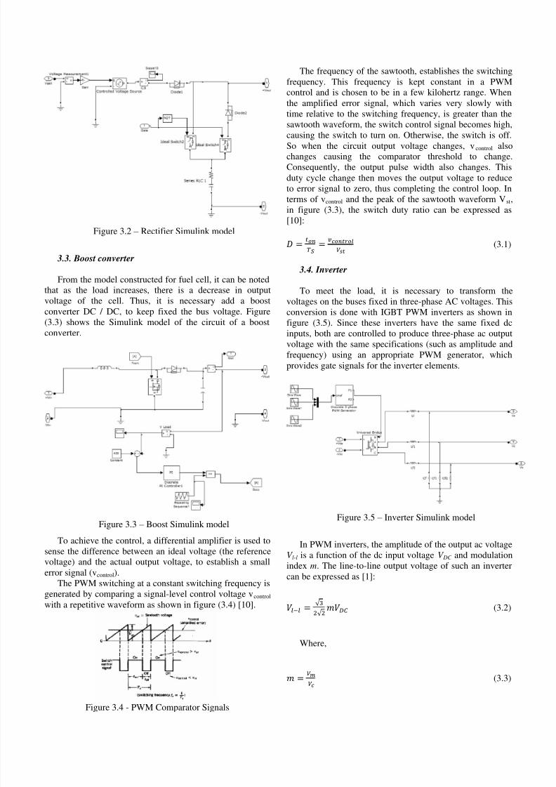
Figure 3.1 – Rectifier Simulink model
3.2. Flywheel
As mentioned previously, to store energy through aflywheel, an electric machine is necessary to make the
conversion of energy. However, as the electric machinecoupled to the flywheel is represented by the capacitorconnected to a DC bus, it is necessary, for the simulating,that the control strategy be different from that presentedwhen a machine performs the conversion of electricalenergy, as happens in real systems.
The flywheel energy storage system has three modes of operation:
Charge mode
Stand-by mode
Discharge mode
In the first case, the capacitor is charged when theenergy demanded by the load is small, and so, the fuel cellsystem generates up to load limit, and the excess power isused to charge the capacitor until its rated voltage. At thismoment, the energy is stored and the system is on the stand-by mode.
However, when the energy required from the fuel cell isgreater than the nominal, the capacitor discharges to meetthe extra energy demanded.
If considered a flywheel, the dynamic of charging/discharging is almost the same.
The control of energy flow is done by means of twodiodes and two keys.
During the low power demand the energy is transferredto accelerating the flywheel until its rated speed. In thismode, energy is stored in the flywheel in the form of kineticenergy. Power is transported over the D1 diode and theflywheel is charged over the S1 switch that is closed. Theflywheel does not provide any power since the S 2 switch isopen. However, when there is a peak demand, the flywheelprovides torque to the machine and slows down. Themachine acts as a generator providing the energy needed tomeet demand. The flywheel is discharged over the S2 switchand D2 diode to satisfy the excess load demand while the S1 switch is open.
From the model constructed for fuel cell, it can be notedthat as the load increases, there is a decrease in outputvoltage of the cell. Thus, it is necessary add a boostconverter DC / DC, to keep fixed the bus voltage. Figure(3.3) shows the Simulink model of the circuit of a boostconverter.
Figure 3.3 – Boost Simulink model
To achieve the control, a differential amplifier is used to
sense the difference between an ideal voltage (the referencevoltage) and the actual output voltage, to establish a smallerror signal (vcontrol).
The PWM switching at a constant switching frequency isgenerated by comparing a signal-level control voltage vcontrol
with a repetitive waveform as shown in figure (3.4) [10].
Figure 3.4 - PWM Comparator Signals
The frequency of the sawtooth, establishes the switchingfrequency. This frequency is kept constant in a PWMcontrol and is chosen to be in a few kilohertz range. Whenthe amplified error signal, which varies very slowly withtime relative to the switching frequency, is greater than thesawtooth waveform, the switch control signal becomes high,
causing the switch to turn on. Otherwise, the switch is off.So when the circuit output voltage changes, v control alsochanges causing the comparator threshold to change.Consequently, the output pulse width also changes. Thisduty cycle change then moves the output voltage to reduceto error signal to zero, thus completing the control loop. Interms of vcontrol and the peak of the sawtooth waveform Vst,in figure (3.3), the switch duty ratio can be expressed as[10]:
(3.1)
3.4. Inverter
To meet the load, it is necessary to transform thevoltages on the buses fixed in three-phase AC voltages. Thisconversion is done with IGBT PWM inverters as shown infigure (3.5). Since these inverters have the same fixed dcinputs, both are controlled to produce three-phase ac outputvoltage with the same specifications (such as amplitude andfrequency) using an appropriate PWM generator, whichprovides gate signals for the inverter elements.
Figure 3.5 – Inverter Simulink model
In PWM inverters, the amplitude of the output ac voltageV l-l is a function of the dc input voltage V DC and modulationindex m. The line-to-line output voltage of such an invertercan be expressed as [1]:
Being, Vm the amplitude of the modulating wave and Vc the carrier amplitude.
4. RESULTS AND DISCUSSIONS
The whole system shown in figure (2.1) was built and
simulated using the software MATLAB / Simulink. Thecalculation of the parameters, as well as all modeling of each system component was performed using the equationsdiscussed in previous chapters. And finally, measurementswere made in the main points of the system that will bediscussed below.
4.1. Load profile
At first, figure (4.1) shows the load profile that thesystem must feed. It is observed that the load varies in anon-periodic and therefore it is necessary that the generationmechanisms be able to respond to load change.
Figure 4.1 - Load profile
4.1. Wind turbine and induction generator
The chosen turbine has a diameter of 24m. As previouslystated, the mechanical power extracted from wind turbinedepends on the extraction coefficient noted Cp(λ,θ), which iscalculated by equation (2.1). The parameters used in thisequation are shown in Table (1).
Table 1 - Parameters of Cp equation
Parameter Value
c1 0.22
c2 116c3 0.4
c4 5
c5 -12.5
c6 0
To find the optimal value of Cp, curves were constructedranging λ from 0 to 12 and θ from 0 to 30. Figure (4.2)shows the curves obtained.
Figure 4.2 - Graph of Cp x λ
Looking at figure (4.2) it is noted that if the angle of inclination of the blades is steeper than 30 °, the value of C p is too small and, consequently, the mechanical powerextracted from wind turbine is small too. Therefore, the bestvalue for C p is about 0.45, with θ equal to 0 and λ of 6.7.
Using equation (2.3), curves were constructed to observe
the relationship between the power extracted from theturbine, the speed of rotation of the blades and wind speed.These curves are shown in figure (4.3). In this figure, it isclear that for each different wind speed, there is a rotationalspeed of greater efficiency. This is a disadvantage of fixedspeed turbine, therefore any changing in wind speed theturbine does not work on its point of maximum efficiency.
Figure 2.3 - Wind power x Turbine speed
Table (2) shows the parameters of the induction machinecoupled to wind turbine. This machine, since the turbinespeed is fixe, has the rotor a cage.
To observe the operation of the system when subjectedto variations in wind speed, the signal shown in figure (4.4)is applied to the input of the wind turbine.
Figure 4.4 - Wind speed
The dynamics of the turbine / machine takes about 15seconds to reach steady state. Then, it was simulated a timeinterval of 55 seconds, and so the system can be seen in awindow of 40 seconds in a permanent state.
From the wind profile shown in figure (4.4), the poweroutput of the generator coupled to the turbine is shown infigure (4.5).
Figure 4.5 - Wind power*
Looking at the picture above it is noted that from thetime 31 the energy supplied by the generator decreases dueto the decrease in wind speed.
4.3. Electrolyzer
The tension generated by the generator coupled to thewind turbine is rectified through the double bridge rectifier.
The parameters of the rectifier are given in table (3).
Table 3 - Double bridge rectifier parametersParameter Value
Snubber resistance of one thyristor
[kΩ]
2
Snubber capacitance of one thyristor
[µF]
0.1
Internal resistance of one thyristor
[mΩ] 1
Pulse width of synchronized 12-pulse
generator [°]80
Filter capacitance [mF] 80
Filter inductance [mH] 25Proportional gain of PI voltage 0.001
control system
Integral gain of PI voltage control
system0.01
Reference voltage [V] 400
The output voltage of the rectifier is shown in figure(4.6). It has a ripple of approximately 3%. As previouslymentioned, decrease the fluctuation in the DC bus, reducelosses in the production of hydrogen and allows get an endproduct more pure.
Figure 4.6 - DC bus
As shown in equation (2.30), hydrogen production isdirectly proportional to the input current of the electrolyzer.The number of moles produced per second is shown infigure (4.7). The production of hydrogen keepsapproximately constant, since the wind turbine can supplythe rated power of 18kW at all the time.
Figure 4.7 - Produced Hydrogen
4.4. Fuel cell and hydrogen tank
All parameters used to model the fuel cell are shown inTable (4). The minimum power extracted from the FC isapproximately 2 kW [1]. Therefore, this system is alwaysable to supply larger quantities of energy in a short period of time.
FC internal resistance ( Rint) [Ω] 0.00303FC absolute temperature (T ) [K] 343
Universal gas constant ( R)
[J(kmol.K)-1]8314.47
Utilization factor (U ) 0.8Water time constant (τ H2O) [s] 18.418Water valve constant ( K H2O)
[kmol(s.atm)-1
]7.716 x 10⁻⁶
The energy supplied by the fuel cell depends on thedemand of the load. Figure (4.8) shows the profile of thepower extracted from the FC. From the second 25, theenergy supplied by wind is not enough to feed the load.Consequently, the difference between the demand of theload and power generated by turbine is supplied by FCsystem.
Figure 4.8 - Fuel cell Power
In the intervals between 34 to 38 and 44 to 49 seconds,
there are two peaks in load demand. The power of fuel cellis constant at its maximum value of approximately 45kW.So, at these points, the load is greater than the sums of theenergy supplied by wind turbine and fuel cells. Therefore,the energy stored in the flywheel is provided to feed theload.
The hydrogen consumed is proportional to current of thefuel cell, as shown in equation (2.26). Consequently, thedemanded amount of hydrogen follows the same pattern of the energy supplied by fuel cells. That is, an increase inenergy supplied also rises the amount of hydrogenconsumed. Figure (4.9) shows the amount of hydrogen, inkmols / s, over time.
Figure 4.9 - Consumed Hydrogen
The amount of hydrogen delivered to the tank over timeis shown in figure (4.10).
Figure 4.10 - Hydrogen delivered to storage tank
The output voltage of the fuel cell is shown in figure(4.11). When, the power extracted from the cell increases,and therefore its current, the output voltage decreases.
Figure 4.11 - Fuel cell voltage
The output voltage of the fuel cell is stabilized at 400 Vthrough the boost converter. The parameters of thisconverter are shown in the table (5).
Table 4 - Boost parametersParameter Value
Inductance [µH] 500Capacitance [mF] 2.7
Semiconductor Type MOSFETRated switching frequency [Hz] 2000Proportional gain of PI voltage
As previously mentioned, in the intervals between 34 to38 and 44 to 49 seconds the load peak is supplied by theflywheel. Figure (4.13) shows the energy delivered by theflywheel. In these moments, it provides a torque to theinduction machine that works as a generator. Thus, theflywheel loses speed as shown in figure (4.14).
Figure 4.13 - Flywheel power
Figure 4.14 - Flywheel speed
The flywheel is required to supply 47kW during 5seconds. Therefore, it is necessary an inertia of at least 20kg.m2.
4.6. Power delivered to load
The DCs voltages are converted into AC throughinverters. Table (6) shows all the parameters of the inverters.
Table 5 - Inverter parametersParameter Value
Snubber capacitance [µF] 0.1
Snubber resistance [kΩ] 2
Semiconductor Type IGBT-DIODEInternal resistance [mΩ] 1
Carrier frequency [kHz] 5
Modulation index 0.98
Frequency output voltage [Hz] 50
Filter inductance [mH] 100
Filter Capacitance [µF] 70
Figure (4.15) shows the output voltage (line to ground)of the inverter.
Figure 4.15 - AC voltage
According to equation (4.1), with an input voltage of 400V DC, and in an index value of 0.98, the line voltage isapproximately 240V.
Finally, after all the mechanisms workingsimultaneously, the energy delivered to the load is shown infigure (4.16).
Figure 4.16 - Power of the system hybrid
In order to make comparison, Figure (4.17) shows theload profile and the profile of power delivered to the load.
0 10 20 30 40 50 60-200
0
200
400
600
800
1000
1200
Time [s]
B o o s t o u t p u t V o l t a g e [ V ]
Boost output voltage
0 10 20 30 40 50 600
0.5
1
1.5
2
2.5
3
3.5
4
4.5
5x 10
4
Time [s]
F l y w h e e l o u t p u t P o w e r [ W ]
Flywheel output Power
0 10 20 30 40 50 601480
1481
1482
1483
1484
1485
1486
1487
Time [s]
F l y w h e e l o u t p u t S p e e d [ r p m ]
Flywheel output Speed
33.65 33.66 33.67 33.68 33.69 33.7 33.71 33.72
-200
-150
-100
-50
0
50
100
150
200
Time [s]
V o l t a g e [ V ]
AC voltage
15 20 25 30 35 40 45 50 55
0.6
0.7
0.8
0.9
1
1.1
1.2
1.3
1.4
x 105
Time [s]
P
o w e r d e l i v e r e d b y t h e s y s t e m [ W ]
Observing figure (4.17), it is shown that there is littledifference between energy demand and energy delivered tothe load. This difference can be taken into account theapproximations used, delayed response of the controllers,variations of time constants, and others.
5. PROPOSALS AND CONCLUSION
A model of a hybrid system composed of a wind turbine,fuel cell and a flywheel as storage form was developed andtested in order to validate its use.
The work shows that even with the dependence on windspeed, using a hybrid system, the wind turbine becomes apowerful means of generation. The results indicate that theenergy storage is a key to those new sources of renewableenergy can be leveraged.
The storage of energy as chemical and mechanical(kinetic) proved to be a solution to the problem of variationin wind speed. An ultracapacitor is an alternative to the useof flywheels. Therefore, energy is stored directly inelectrical form and it is not necessary to convert it, as in thecase of the flywheel.
As discussed earlier, one of the main difficulties in usingthe fuel cell is the acquisition and storage of hydrogen. Thehydrogen must be kept at high pressures and lowtemperatures so it can be stored in quantities that can beutilized. To that end, several technologies have beendeveloped with the purpose of bringing this facility up to acompetitive market price. An alternative to better understandthe problem of hydrogen storage tank would be a model thattakes into account its internal pressure as a function of theflow of hydrogen.
Due to the dynamic model presented to the turbine, theresponse time of the simulation showed that long. Theturbine / generator took about 15 seconds to reach the steadystate. The long simulation time created difficulties inobtaining and analyzing the results.
An alternative to better use the potential of wind is thereplacement of fixed speed generator for a variable speed.As shown in figure (4.3), if the system works with a variablespeed generator, it is possible to extract energy from the
wind with maximum efficiency all the time. That is, varyingthe speed of the generator, for each value of wind speed, thatallows the turbine to provide maximum power possible to beextracted from the wind. Thus it is possible to reduce thesize of the fuel cell.
Finally, although there is little difference between the
load profile and the energy delivered, the response of thehybrid system has proved satisfactory. Figure (4.17) showsthat the simulated system can be used as a stand-alonesystem to supply loads away from the grid. However, it isnecessary a more in-depth about the transmission anddistribution systems, as well as a more concrete analysis of several other components such as pumps, valves and motors.
6. REFERENCES
1. O.C. Onar, M. Uzunoglu, M.S. Alam, “Dynamic modeling,design and simulation of a wind/fuel cell/ultra-capacitor-basedhybrid power generation system”, Journal of Power Sources,
161 (2006), pp.707-7222. L. Leclercq, C. Saudemont, B. Robyns, G. Cimuca, M.M.
Radulescu, “Flywheel energy storage system to improve theintegration of wind generator into a network”, Electromotion,10 (2003), pp. 641-646.
3. MATLAB SimPowerSystems for Use with Simulink User’sGuide, Version 4.1.1,http://www.mathworks.com/access/helpdesk/help/pdfdoc/physmod/powersys/powersys.pdf .
4. S. Heier, “Grid Integration of Wind Energy ConversionSystems”, JohnWiley & Sons Ltd, New York, (1998).
5. E. Muljadi, C.P. Butterfield, “Pitch-controlled variable-speedwind turbine generation”, IEEE Trans.Industry Appl., 37/1(2001), pp. 240-246.
6.
M. Uzunoglu , M.S. Alam, “ Dynamic modeling, design andsimulation of a PEM fuel cell/ultra-capacitor hybrid system forvehicular applications”, Energy Conversion and Management,48 (2007), pp. 1544-1553
7. B. Bolund, H. Bernhoff, M. Leijon, “Flywheel energy and power storage systems”, Renewable and Sustainable EnergyReviews, 11 (2007), pp. 235 – 258.
8. N. Hamsic, A. Schmelter, A. Mohd, E. Ortjohann, E. Schultze,A. Tuckey, J. Zimmermann, “Increasing Renewable EnergyPenetration in Isolated Grids Using a Flywheel Energy StorageSystem”, POWERENG (2007).
9. S. Satish, “ Modeling and Analysis of a Flywheel EnergyStorage System for Voltage Sag Correction”, A Thesispresented in partial Fulfillment of the Requirements for the
Degree of Master of Science With a Major in ElectricalEngineering, College of Graduate Studies University of Idaho,(2003).
10. M . S. Rahman, “Buck Converter Design Issues”, Master thesisin Electronic Devices, Linköping Institute of Technology,(2007)