24
ASIC for MEMS UiO 3 November, 2005

ASIC for MEMS
UiO
3 November, 2005

- 1 -
ASIC for MEMS
Agenda 3/11-05:
• Introduction
• Sensor-ASIC
• (Some) Practical Aspects of ASIC-Design
• Wrap-up

- 2 -
Introduction
Who am I?• John Raaum. M.Sc. NTH 1991.• 2 years at the Norwegian Defense Research Establishment (FFI)• At Nordic Semiconductor since ’94. • At SensoNor ’98.• Senior Technical Manager• Personal experience from the following sensor-applications:
On-chip temperature sensorOn-chip voltage monitorLow-Power Piezo-resistive sensor for Tire-PressureResonating sensor for airbag applicationPiezo-resistive sensor for airbag application
Optical-loop for keyless entryCapacitive interface for roll-over sensor (angular rate sensor)
Ultrasonic flow-meter
- 3 -
NORDIC SEMICONDUCTOR IS
A 20 year old Fabless Semiconductor Company
Producer of standard ”off-the-shelf” RF components
Turn-key developer and supplier of custom components
Intellectual Property (IP) supplier with advanced A/D, D/A and RF modules
Worldwide company with representatives on all continents
A leading Norwegian Technology Company listed on the Norwegian Stock Exchange
- 4 -
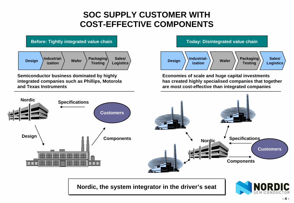
SOC SUPPLY CUSTOMER WITHCOST-EFFECTIVE COMPONENTS
Industrial-ization Wafer Packaging
TestingSales/
LogisticsDesign
Before: Tightly integrated value chain
Semiconductor business dominated by highly integrated companies such as Phillips, Motorola and Texas Instruments
Economies of scale and huge capital investments has created highly specialised companies that together are most cost-effective than integrated companies
Industrial-ization Wafer Packaging
TestingSales/
LogisticsDesign
Today: Disintegrated value chain
Nordic, the system integrator in the driver’s seatNordic, the system integrator in the driver’s seat
Customers
Nordic Specifications
Components
Customers
Nordic Specifications
ComponentsDesign
- 5 -
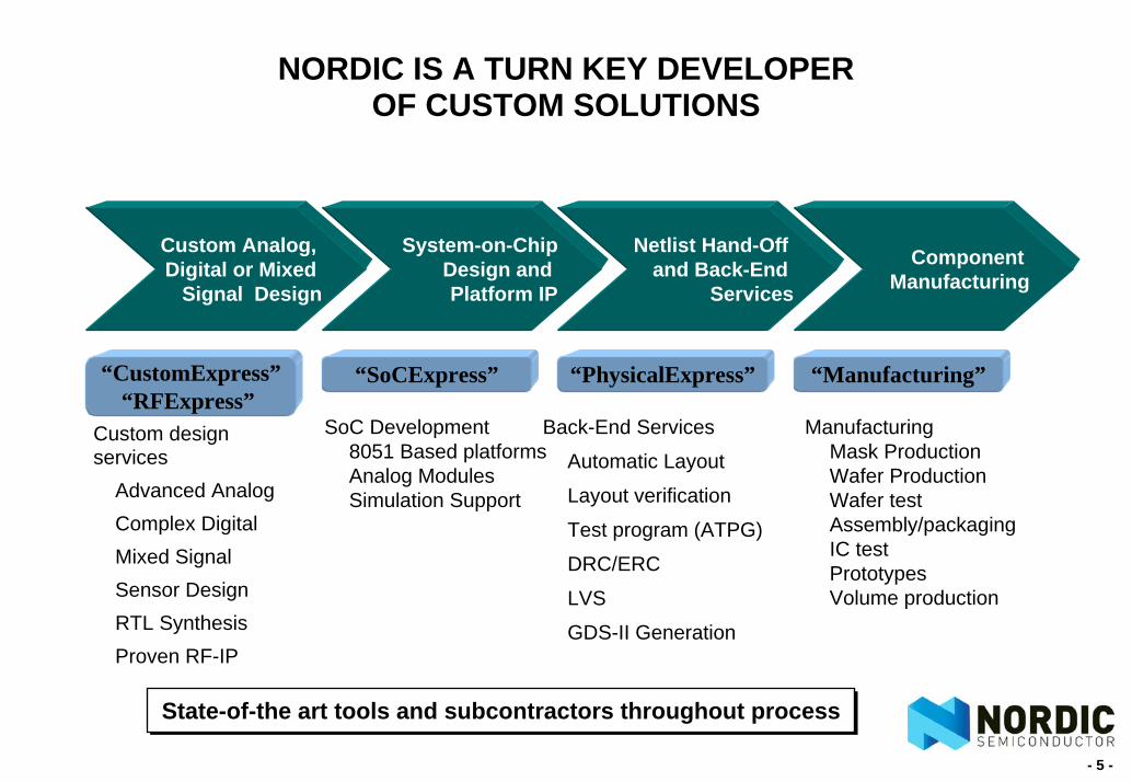
NORDIC IS A TURN KEY DEVELOPER OF CUSTOM SOLUTIONS
Custom design services
Advanced AnalogComplex DigitalMixed SignalSensor DesignRTL SynthesisProven RF-IP
Custom Analog, Digital or Mixed
Signal Design
System-on-ChipDesign and Platform IP
Netlist Hand-Off and Back-End
Services
Component Manufacturing
“SoCExpress” “PhysicalExpress” “Manufacturing”“CustomExpress”“RFExpress”
SoC Development8051 Based platformsAnalog ModulesSimulation Support
ManufacturingMask ProductionWafer ProductionWafer testAssembly/packagingIC testPrototypesVolume production
Back-End Services
Automatic Layout
Layout verification
Test program (ATPG)
DRC/ERC
LVS
GDS-II Generation
State-of-the art tools and subcontractors throughout processState-of-the art tools and subcontractors throughout process

- 6 -
Sensor-ASICs
The mission:
Signal conditioning, temperature compensation and data formatting of raw data from various types of sensors
Why?Improved linearity, noise, accuracy, …
How?Custom sensor-ASICs from Nordic Semiconductor

- 7 -
The operational chain
Key Issue:Conversion of physical parameters to electrical signals in a mechanical setting!
Bulk Micro-Mashined
Sensor-DieASIC uC Squid-Driver
Measurement
SensingElement
SignalConditioning
ParameterMonitoring
AirbagDeployment
Decision Action
F = m aExcite
Measure

- 8 -
Sensor-ASICs
Typical spec of sensing element:
• Sensitivity with large tolerance: +/-30%
• High temperature drift of sensitivity: +/-15%
• Large zero-point error: +/-Full Scale Output (FSO)
• Large noise bandwidth: Mechanical filter with resonances
• Analog output (Whetstone measurement bridge)
• Capacitive / resonating element - need for excitation
• Built-in self-test facility

- 9 -
Sensor-ASICs
Typical spec of sensor product (Automotive example):
• Sensitivity with tight tolerance: +/-3%.
• Low temperature drift of sensitivity: +/-1.5%.
• Small zero-point error: +/-1% of FSO.
• Well controlled noise bandwidth.
• Minimised group delay.
• Any output format: Analog, PWM, SPI, parallel digital, current loop, ...
Even better accuracy for high end sensors.
- 10 -
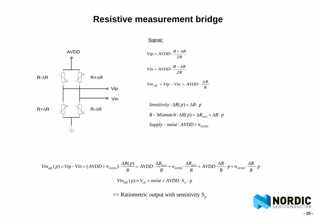
Resistive measurement bridge
AVDD
R+∆R
R-∆R
Vip
Vin
R-∆R
R+∆R
RRRAVDDVip
2∆+
⋅=
RRRAVDDVin
2∆−
⋅=
RRAVDDVinVipVin diff
∆⋅=−=
Signal:
pRRpRMismatchR zero ⋅∆+∆=∆− )(:
pRRnp
RRAVDD
RRn
RRAVDD
RpRnAVDDVinVippVin AVDD
zeroAVDD
zeroAVDDdiff ⋅
∆⋅+⋅
∆⋅+
∆⋅+
∆⋅=
∆⋅+=−=
)()()(
=> Ratiometric output with sensitivity Sp
pSAVDDnoiseVpVin pofsdiff ⋅⋅++≈)(
pRpRySensitivit ⋅∆=∆ )(:
AVDDnAVDDnoiseSupply +− :

- 11 -
Sensor / ASIC front-end
Sensing elementwith
MeasurementBridge
Diff2Sing LNA
ADCTo Digital Part of ASIC
AVDD
AVSS
Physical Input
Ratio-metric cancellation:• AVDD-dependent input signal• AVDD-dependent ADC reference voltages

- 12 -
Accuracy Management
Purpose of Signal Conditioning in ASIC:Reduce overall tolerance over PVT from +/-50-150% to +/-1-5%!
Typical Overall Transfer Function:
S(T,P) is typically a programmable N-order polynomal implementing the inverse temperature drift of Sp(T,P).
G0(P) is a programmable gain adjusting the sensitivity at room temperature.
High pass filters remove unintentional zero voltage (offset voltage).
),()(),(),,,( 0 PTSPGpPTSAVDDPTAVDDpV pout ⋅⋅⋅⋅=

- 13 -
Typical Signal Conditioning
When you know your signal chain - Do you know you input signal??
Long Time Constant
Pass Band AttenuationPulse Distortion
Full Scale Output (FSO)Adjustment
On-chip / Integrated
Compensation Equations
Signal Coding (PWM, Serialdigital, Current Loop, ...)
SignalSource
High PassFilter
Low PassFilter PGA Temperature
Compensation
TemperatureSensor
SignalEncoding
DC + ACBandwidth
- 14 -
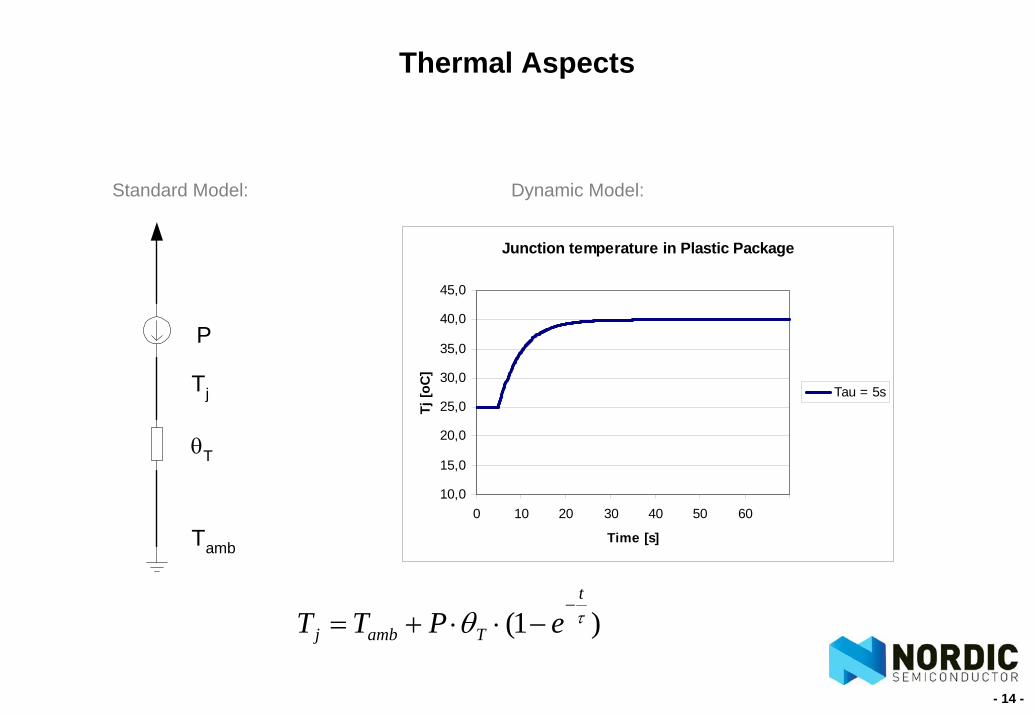
Thermal Aspects
P
θT
Tamb
Tj
Junction temperature in Plastic Package
10,0
15,0
20,0
25,0
30,0
35,0
40,0
45,0
0 10 20 30 40 50 60
Time [s]
Tj [o
C]
Tau = 5s
Standard Model: Dynamic Model:
)1( τθt
Tambj ePTT−
−⋅⋅+=
- 15 -
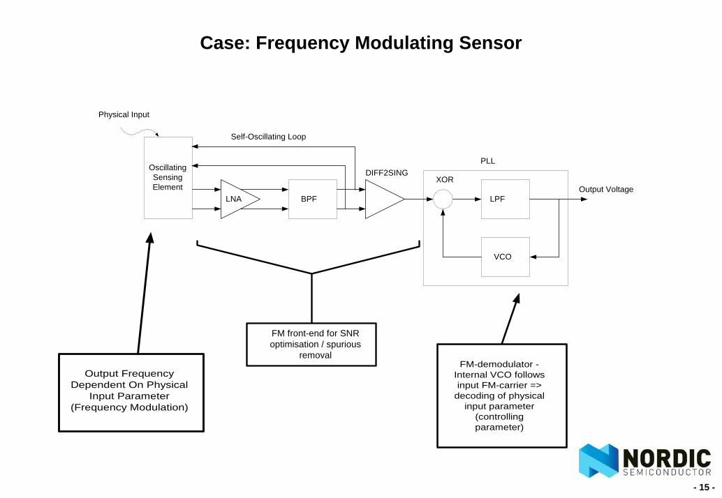
Case: Frequency Modulating Sensor
Output FrequencyDependent On Physical
Input Parameter(Frequency Modulation)
FM-demodulator -Internal VCO followsinput FM-carrier =>
decoding of physicalinput parameter
(controllingparameter)
OscillatingSensingElement
Physical Input
LNA BPF
DIFF2SINGXOR
LPF
VCO
Output Voltage
PLL
Self-Oscillating Loop
FM front-end for SNRoptimisation / spurious
removal
- 16 -
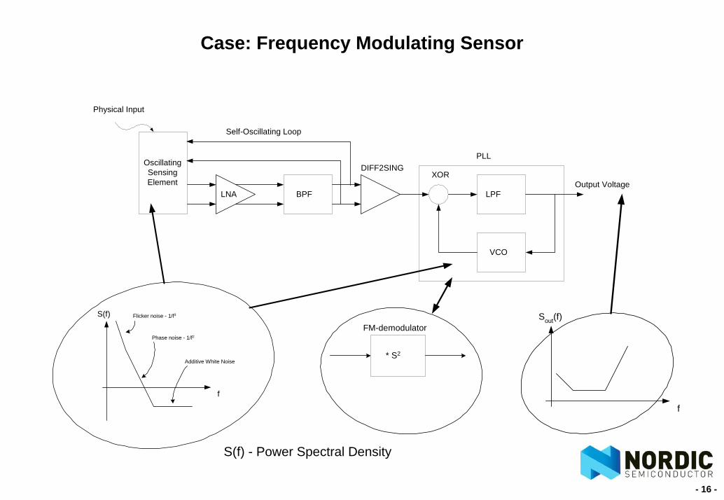
OscillatingSensingElement
Physical Input
LNA BPF
DIFF2SINGXOR
LPF
VCO
Output Voltage
PLL
Self-Oscillating Loop
Case: Frequency Modulating Sensor
S(f) Flicker noise - 1/f3
Phase noise - 1/f2
Additive White Noise
f
* S2
FM-demodulatorSout(f)
f
S(f) - Power Spectral Density

- 17 -
Tools and Methology
Essential for Design of Sensor-ASICs:• Simulation Model of Sensing Element• System and Signals Know-How
Make Your Spec Executable:• Matlab/Simulink• HDL-modelling• ADMS• SPICE• Careful Budgeting (Monte Carlo Analysis)
- 18 -
Sensor-ASICs
What to look for in Sensor- / ASIC-spec?• ppm accuracy (including noise)• Very low frequency filters• Low power at elevated temperatures• Start-up time• Testability• ...

- 19 -
Define Your Design Environment
Specification with Parameter Budgeting Power-strategy ESD-strategy Bias-strategy Test-strategy Floorplan (Area-estimates with Seal and Scribe) Analog vs Digital - Optimize cost vs performance Process Options - Optimize cost vs performance

- 20 -
PrePre--studystudyProjectProject
PrototypePrototypeTest
Industr.Industr.ProductionProduction
New versionRedesign
TIME
ConceptConceptstudystudy
1. 2.3.
4.5.
6.7.
1. Concept study: 2-3 weeks. Possible to use ASIC?
2. Pre-study: 3-6 weeks. Specification of ASIC.
3. Project: 3-6 months ASIC development (depending on project complexity)
4. Prototype production: 6-12 weeks. Implementation of production test..
5. Test at customer site: 4 weeks. Prototype test in customers application.
6. Industrialisation: 8-12 weeks. Qualification and transfer to production.
7. Production: Lot acceptance and yield monitoring..
Workflow ASIC project

- 21 -
Reliability #1/2
All stages in the product development includes product reliability tasks.
The overall target is to create a robust, high quality product, meeting the specification and resistant to expected external stress.
The target of the product qualification is to prove that the product is resistant to expected external stress.
- 22 -
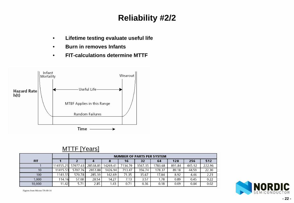
Reliability #2/2
• Lifetime testing evaluate useful life• Burn in removes Infants• FIT-calculations determine MTTF
Figures from Micron TN-00-14
MTTF [Years]

- 23 -
Wrap-up
What should be remembered?• Caution: Signal Conversion in Mechanical System• Caution: Be Aware of Input Signal Spectrum• Caution: Be Aware of Side-Effects of Important Functional Modules
(Thermal effects ...)• Caution: Unable to Make Simulation Model of Your Sensor => Unable to
Design Signal Conditioning? • Caution: Always Utilise Best Practice Mixed-Signal Design Methology• Caution: Don’t forget cost optimisation, production test and reliability!


