Ph.D. Dissertation Defense A System-Theoretic Safety Engineering Approach for Software-Intensive Systems Asim Abdulkhaleq Stuttgart, February 6 th 2017 University of Stuttgart @AbdulkhaleqAsim 06-02-2017 Ph.D. Defense Committee: Prof. Dr. Stefan Wagner Prof. Dr. Nancy Leveson Prof. Dr. Dr. h. c. Frank Leymann Prof. Dr. Ulrich Hertrampf Prof. Dr. Ralf Küsters www.XSTAMPP.de 1/30
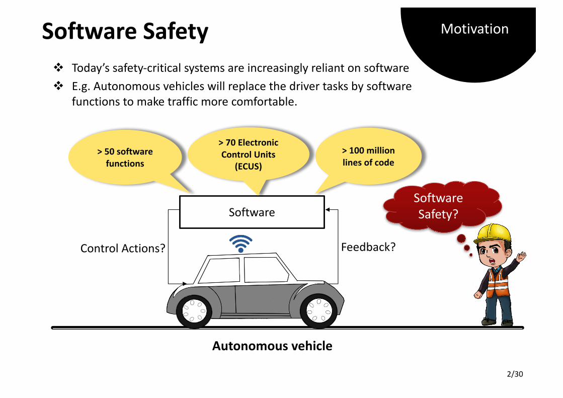
v Today’ssafety-criticalsystemsareincreasinglyreliantonsoftwarev E.g.Autonomousvehicleswillreplacethedrivertasksbysoftware
functionstomaketrafficmorecomfortable.
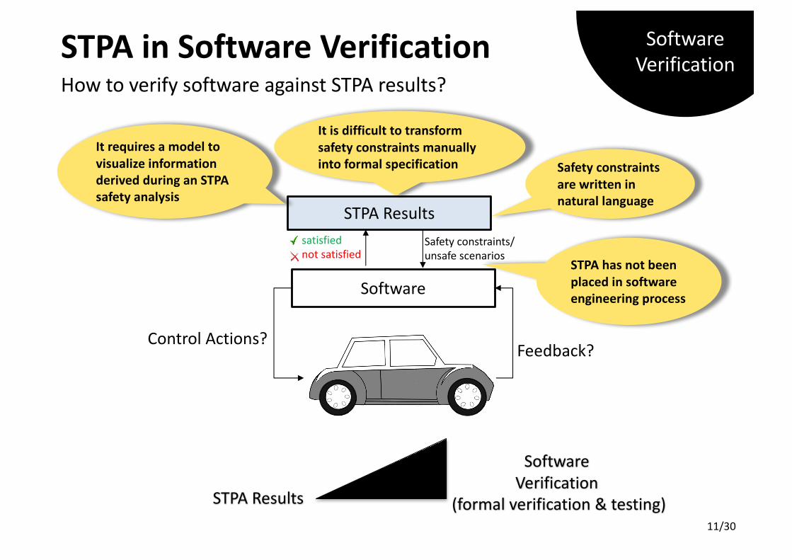
Software
ControlActions? Feedback?
>100millionlinesofcode
>70ElectronicControlUnits
(ECUS)>50softwarefunctions
Autonomousvehicle
Motivation
2/30
Agenda
v Motivation
v Introduction
Ø ProblemStatement
Ø ResearchObjectives
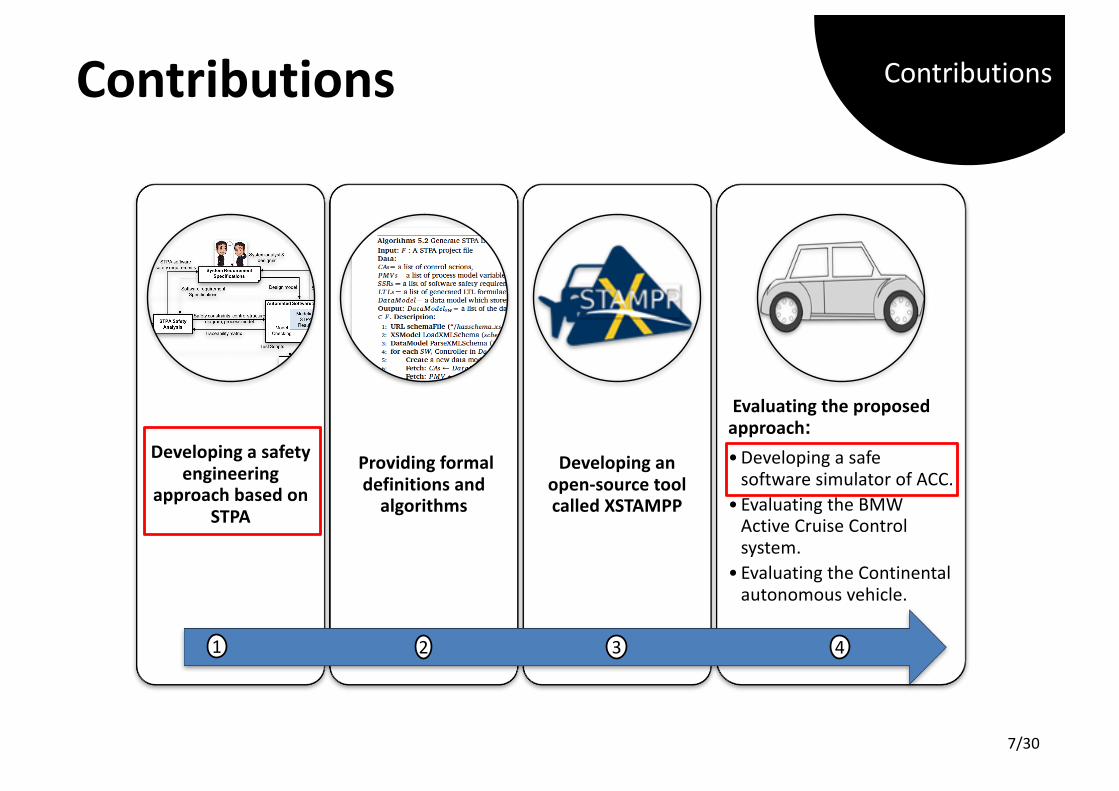
Ø Contributions
v Background
Ø SafetyAnalysisTechniques
Ø SoftwareVerification
v ProposedApproach
v IllustrativeExample:AdaptiveCruiseControlSystemwithStop-and-Gofunction
v Conclusion&FutureWork
Agenda
3/30
System
4/30
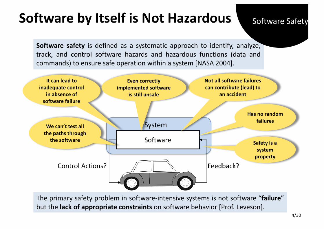
SoftwarebyItselfisNotHazardous
Software
ControlActions? Feedback?
Notallsoftwarefailurescancontribute(lead)to
anaccident
Wecan’ttestallthepathsthrough
thesoftware
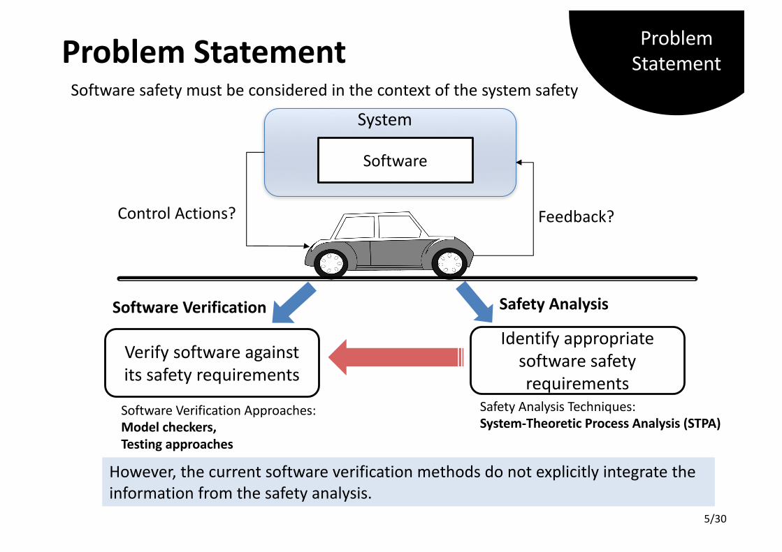
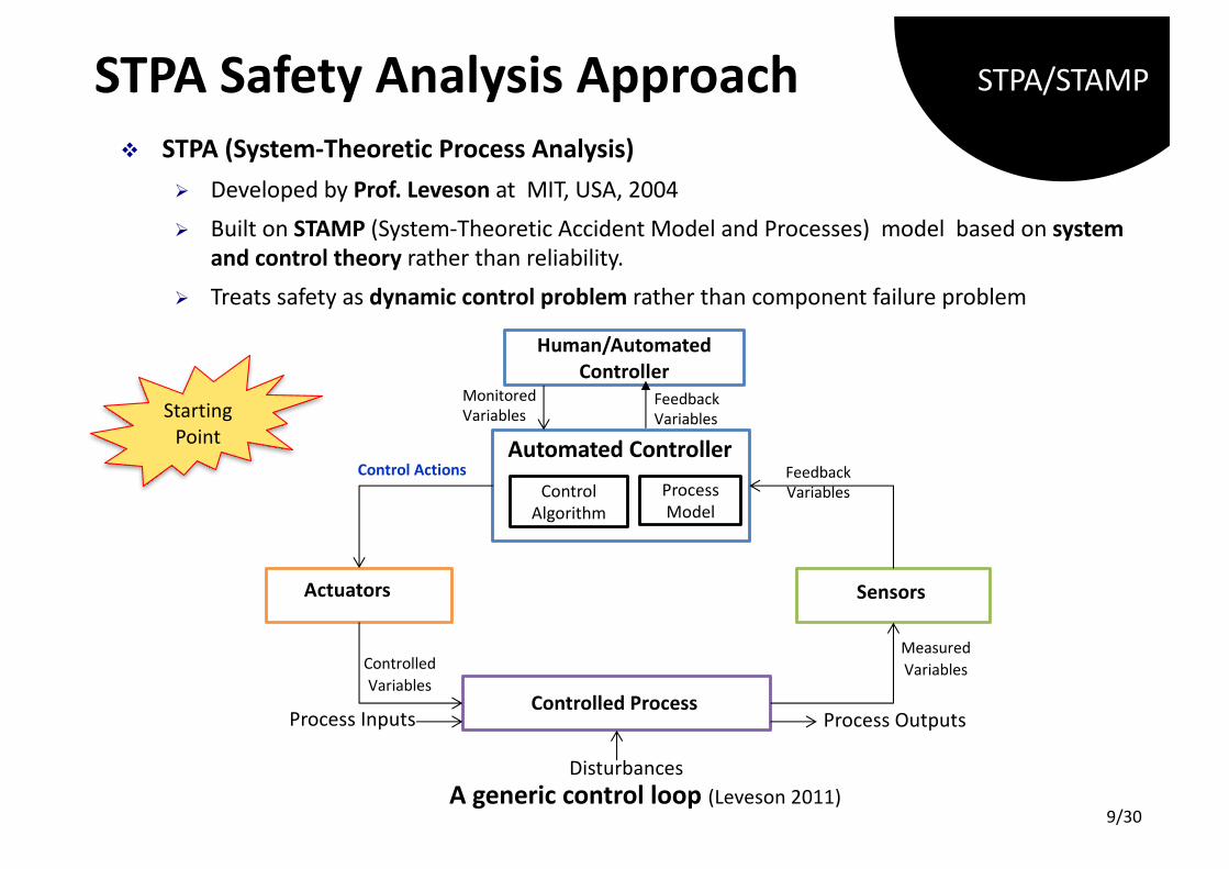
The primary safety problem in software-intensive systems is not software “failure”but the lack of appropriate constraints on software behavior [Prof. Leveson].
Itcanleadtoinadequatecontrol
inabsenceofsoftwarefailure
Evencorrectlyimplementedsoftware
isstillunsafe
Hasnorandomfailures
Safetyisasystemproperty
Software safety is defined as a systematic approach to identify, analyze,track, and control software hazards and hazardous functions (data andcommands) to ensure safe operation within a system [NASA 2004].
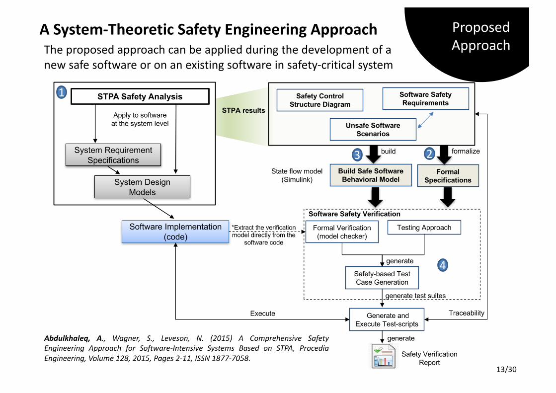
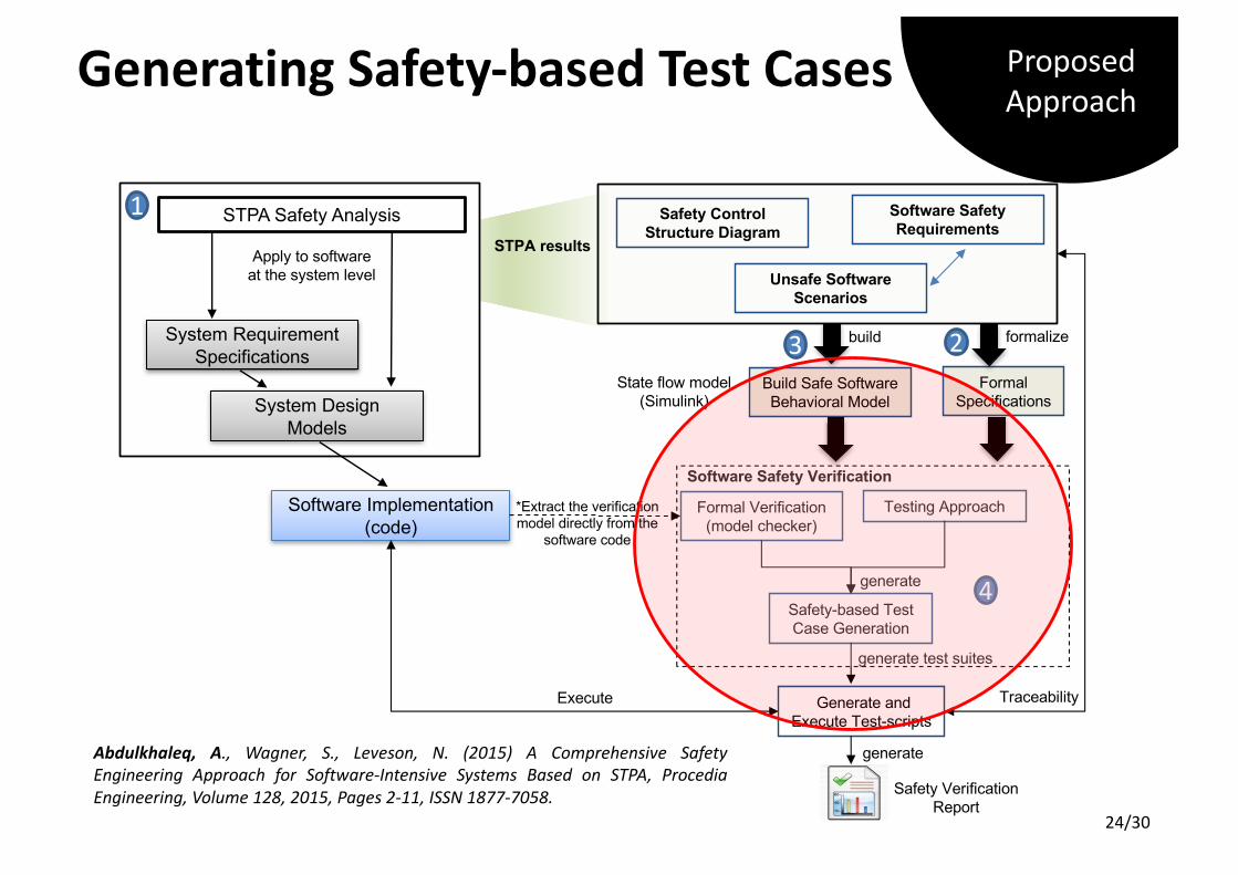
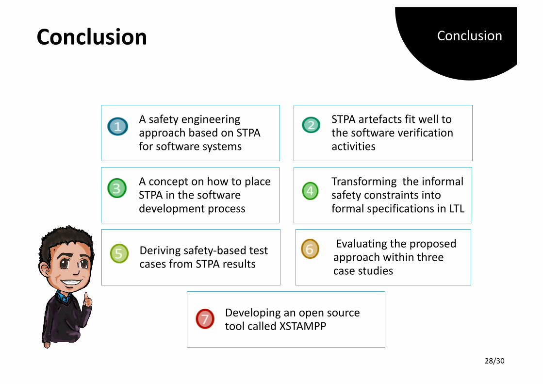
📌 To develop a safety engineering approach based on STPA which offersseamless safety analysis and software verification activities to helpsoftware and safety engineers in:
Ø deriving the appropriate software safety requirementsØ formally verifying them, andØ generating safety-based test cases to recognize the associated software risks.
📌 To develop an open-source tool to support the proposed approach
Abdulkhaleq, A., Wagner, S., Leveson, N. (2015) A Comprehensive SafetyEngineering Approach for Software-Intensive Systems Based on STPA, ProcediaEngineering, Volume 128, 2015, Pages 2-11, ISSN 1877-7058.
ProposedApproach
13/30
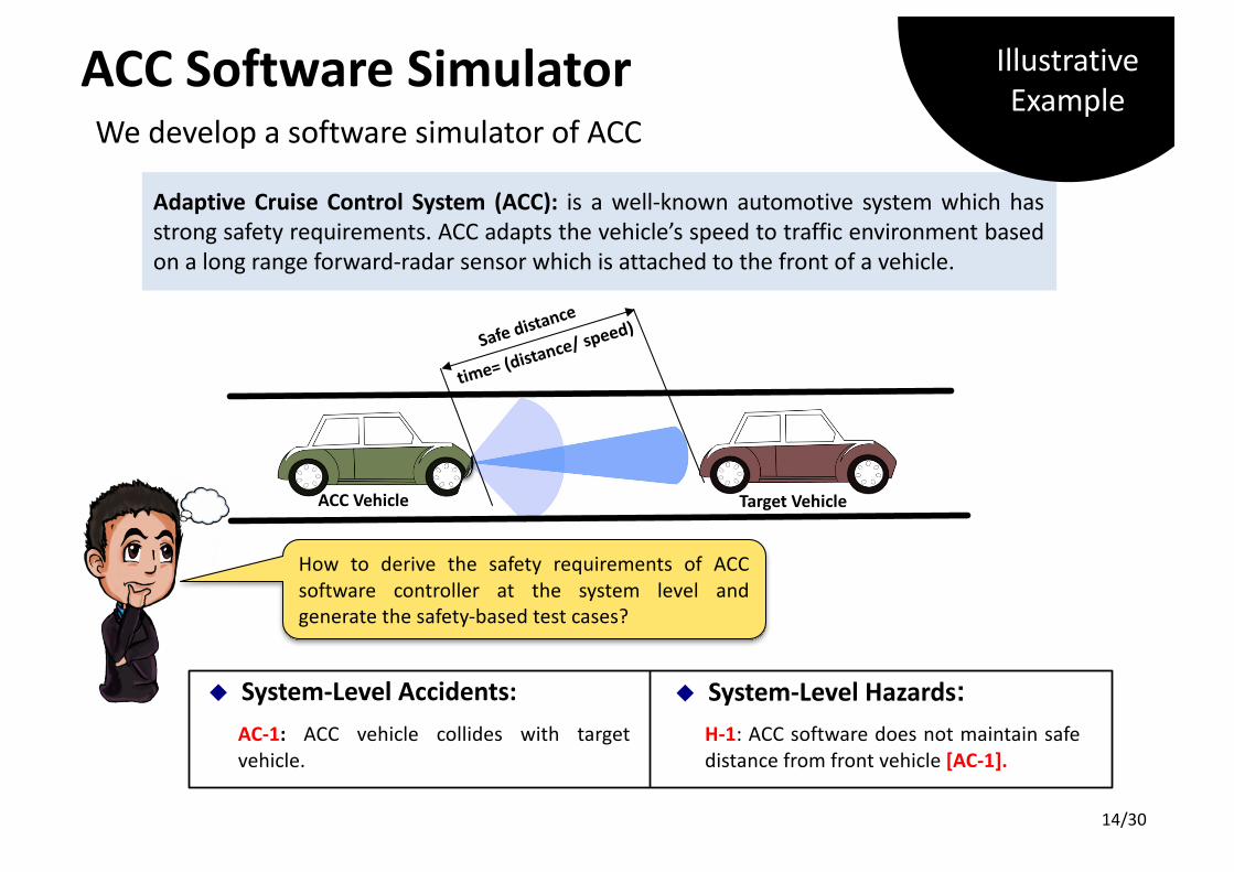
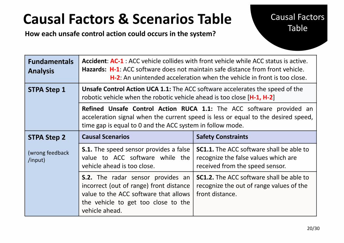
u System-Level Hazards:H-1: ACC software does not maintain safedistance from front vehicle [AC-1].
u System-Level Accidents:AC-1: ACC vehicle collides with targetvehicle.
How to derive the safety requirements of ACCsoftware controller at the system level andgenerate the safety-based test cases?
Adaptive Cruise Control System (ACC): is a well-known automotive system which hasstrong safety requirements. ACC adapts the vehicle’s speed to traffic environment basedon a long range forward-radar sensor which is attached to the front of a vehicle.
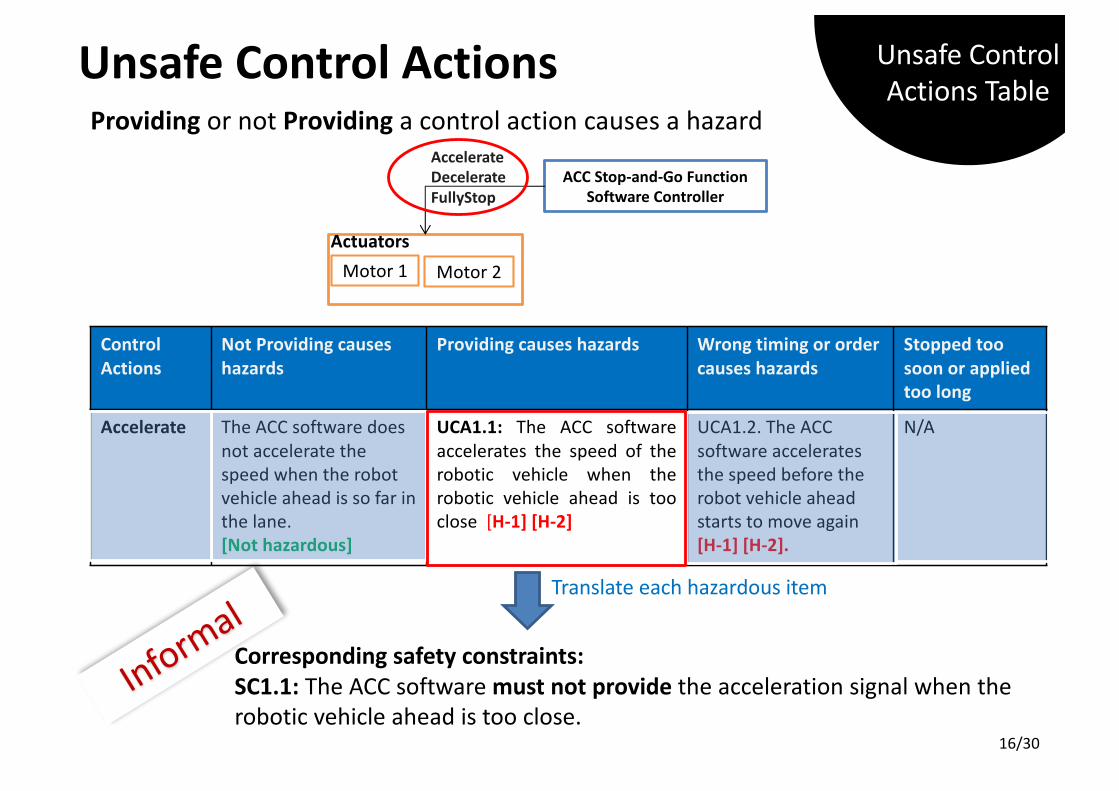
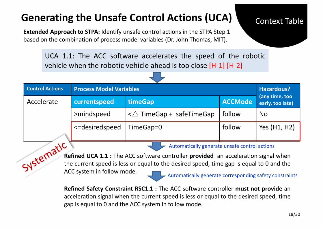
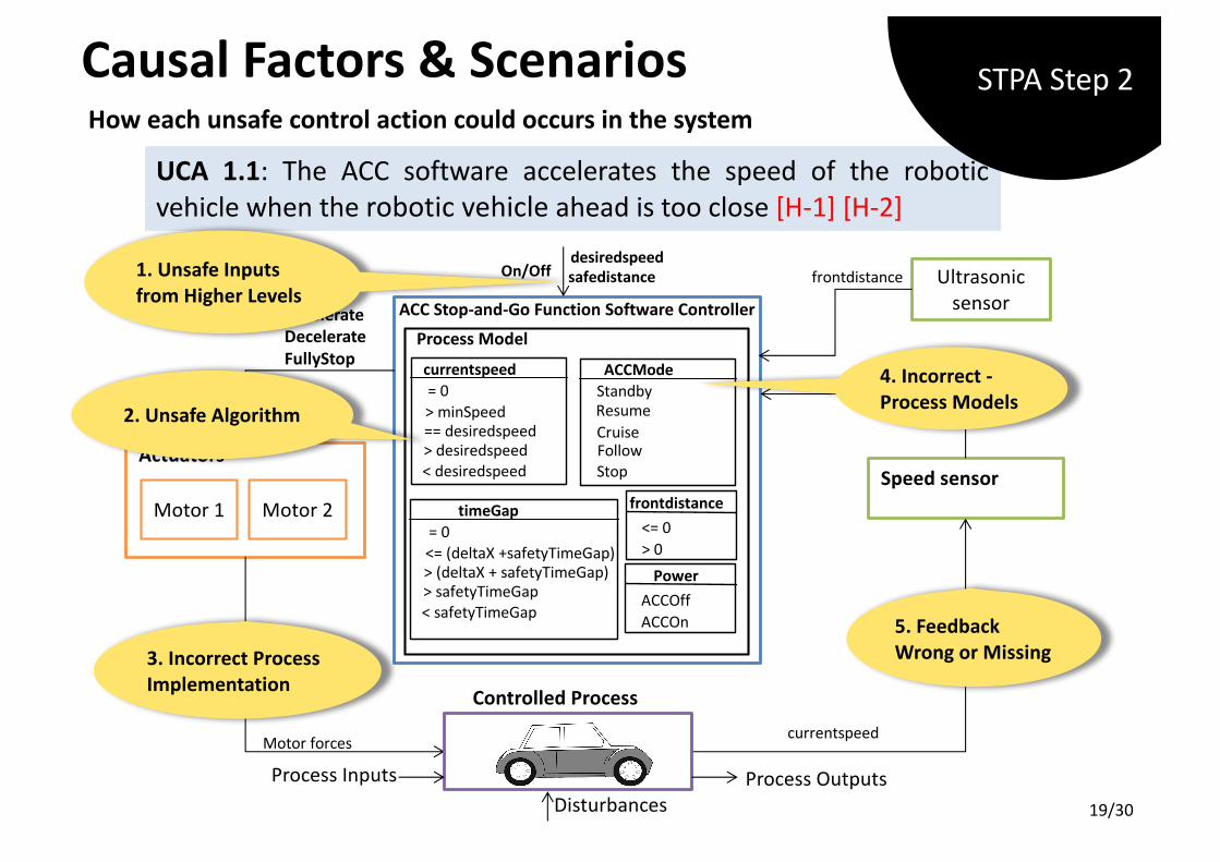
UCA 1.1: The ACC software accelerates the speed of the roboticvehicle when the robotic vehicle ahead is too close [H-1] [H-2]
GeneratingtheUnsafeControlActions(UCA)Extended Approach to STPA: Identify unsafe control actions in the STPA Step 1based on the combination of process model variables (Dr. John Thomas, MIT).
Refined UCA 1.1 : The ACC software controller provided an acceleration signal whenthe current speed is less or equal to the desired speed, time gap is equal to 0 and theACC system in follow mode.
Refined Safety Constraint RSC1.1 : The ACC software controller must not provide anacceleration signal when the current speed is less or equal to the desired speed, timegap is equal to 0 and the ACC system in follow mode.
Refined Unsafe Control Action RUCA 1.1: The ACC software provided anacceleration signal when the current speed is less or equal to the desired speed,time gap is equal to 0 and the ACC system in follow mode.
STPA Step2
(wrong feedback/input)
Causal Scenarios SafetyConstraints
S.1. The speed sensor provides a falsevalue to ACC software while thevehicle ahead is too close.
S.2. The radar sensor provides anincorrect (out of range) front distancevalue to the ACC software that allowsthe vehicle to get too close to thevehicle ahead.
CausalFactors&ScenariosTableHow each unsafe control action could occurs in the system?
CausalFactorsTable
20/30
Formalisation ofSTPAResults
21/30
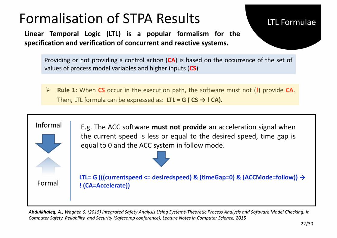
Formalisation ofSTPAResultsLinear Temporal Logic (LTL) is a popular formalism for thespecification and verification of concurrent and reactive systems.
Ø Rule 1: When CS occur in the execution path, the software must not (!) provide CA.Then, LTL formula can be expressed as: LTL = G ( CS → ! CA).
Providing or not providing a control action (CA) is based on the occurrence of the set ofvalues of process model variables and higher inputs (CS).
E.g. The ACC software must not provide an acceleration signal whenthe current speed is less or equal to the desired speed, time gap isequal to 0 and the ACC system in follow mode.
Abdulkhaleq, A., Wagner, S., Leveson, N. (2015) A Comprehensive SafetyEngineering Approach for Software-Intensive Systems Based on STPA, ProcediaEngineering, Volume 128, 2015, Pages 2-11, ISSN 1877-7058.
ProposedApproach
24/30
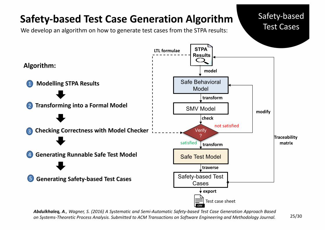
Safety-basedTestCaseGenerationAlgorithmWe develop an algorithm on how to generate test cases from the STPA results:
Algorithm:
Abdulkhaleq, A., Wagner, S. (2016) A Systematic and Semi-Automatic Safety-based Test Case Generation Approach Basedon Systems-Theoretic Process Analysis. Submitted to ACM Transactions on Software Engineering and Methodology Journal.
Safe Behavioral Model
Verify ?
Safety-based Test Cases
traverse
notsatisfied
satisfied
modify
export
LTLformulae STPAResults
Traceabilitymatrix
transform
check
SMV Model
Safe Test Model
model
GeneratingSafety-basedTestCases
1 ModellingSTPAResults
2 TransformingintoaFormalModel
3 CheckingCorrectnesswithModelChecker
4 GeneratingRunnableSafeTestModel
5
Testcasesheet
transform
Safety-basedTestCases
25/30
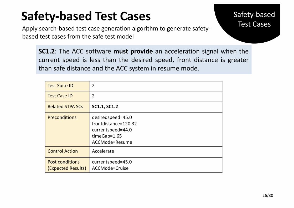
SC1.2: The ACC software must provide an acceleration signal when thecurrent speed is less than the desired speed, front distance is greaterthan safe distance and the ACC system in resume mode.
SC1.2: The ACC software must provide an acceleration signal when thecurrent speed is less than the desired speed, front distance is greaterthan safe distance and the ACC system in resume mode.