Capt DJ Butcher , Canadian Forces Aerospace and Telecommunications Engineering Support Squadron (ATESS) Mr. Yushi Sun , Innovative Materials Testing Technologies (IMTT) Capt DJ Butcher , Canadian Forces Aerospace and Telecommunications Engineering Support Squadron (ATESS) Mr. Yushi Sun , Innovative Materials Testing Technologies (IMTT) Lower Layer Crack Detection in Thick Complex Aircraft Structures Using Flat Geometry Remote Field Eddy Current Technique ASIP 2006
Transcript
Capt DJ Butcher, Canadian Forces Aerospace and Telecommunications Engineering Support Squadron (ATESS)Mr. Yushi Sun, Innovative Materials Testing Technologies (IMTT)
Capt DJ Butcher, Canadian Forces Aerospace and Telecommunications Engineering Support Squadron (ATESS)Mr. Yushi Sun, Innovative Materials Testing Technologies (IMTT)
Lower Layer Crack Detection in Thick Complex Aircraft Structures Using Flat Geometry Remote Field
Eddy Current Technique
ASIP 2006
OutlineOutline
• Background on CF• Limitation of Current Technologies• Understanding Remote Field Eddy Current as Applied to
Flat Geometries (FG_RFEC)• Description of Test Pieces (3 CF Inspection Problems)• Results of FG_RFEC applied to the 3 Inspection
Problems• Further Work
• Background on CF• Limitation of Current Technologies• Understanding Remote Field Eddy Current as Applied to
Flat Geometries (FG_RFEC)• Description of Test Pieces (3 CF Inspection Problems)• Results of FG_RFEC applied to the 3 Inspection
Problems• Further Work
BackgroundBackground
• The Canadian Forces (CF) is currently flying many aging fleets:– CC130 (over 40 years old )– CP140 (P3) (over 25 years old)– CF118 (F18) (over 25 years old)– CH124 Sea King (over 40 years old)– CC114 Buffalo (over 50 years old)
• The Canadian Forces (CF) is currently flying many aging fleets:– CC130 (over 40 years old )– CP140 (P3) (over 25 years old)– CF118 (F18) (over 25 years old)– CH124 Sea King (over 40 years old)– CC114 Buffalo (over 50 years old)
BackgroundBackground
• Recent aging aircraft issues have required detailed inspections of thick complex structure– SB82-790 for the CC130 CW – Risk Analysis of Lower Wing Splices of the CP140
(P3) as determined from the Service Life Assessment Program (SLAP)
– Risk Analysis of the F18 front spar as determined from IFFOS
Limitations of Current TechnologiesLimitations of Current Technologies• UT
– Many of the CF multi-layer structures (i.e. CP140 and CC130 wing planks) are not bonded between faying surfaces required for the transmission of sound
• ET– Traditional applications of eddy current affected by
thick structure, ferrous fasteners, and complex geometry (first and second layer edges)
• RT– Insufficient sensitivity to sought defect size and
orientation
• UT– Many of the CF multi-layer structures (i.e. CP140 and
CC130 wing planks) are not bonded between faying surfaces required for the transmission of sound
• ET– Traditional applications of eddy current affected by
thick structure, ferrous fasteners, and complex geometry (first and second layer edges)
• RT– Insufficient sensitivity to sought defect size and
orientation
Understanding RFECUnderstanding RFEC
• Remote field eddy currents are generated by the same electromagnetic phenomena as traditional eddy currents
• First application in 1951 and widely used since for NDT of metallic pipes and tubing
• Requires a driver pick-up or reflection-differential coil configuration (Rx coil must be isolated from Tx coil)
• In tube/pipe inspections the pick-up coil signal is a function of:– Wall condition– Thickness– Permeability and– Conductivity
Understanding RFECUnderstanding RFEC
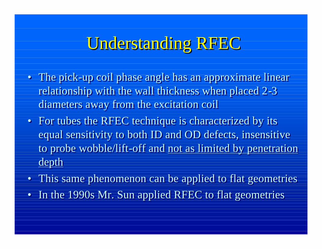
• The pick-up coil phase angle has an approximate linear relationship with the wall thickness when placed 2-3 diameters away from the excitation coil
• For tubes the RFEC technique is characterized by its equal sensitivity to both ID and OD defects, insensitive to probe wobble/lift-off and not as limited by penetration depth
• This same phenomenon can be applied to flat geometries• In the 1990s Mr. Sun applied RFEC to flat geometries
Applying RFEC to Flat GeometriesApplying RFEC to Flat Geometries
• As noted previously, the EM energy flow passes through the platewall twice.
• In the tube case the induced eddy currents inside the wall restricts the flux pattern from expanding axially resulting in the rapid attenuation of the direct coupling field
• If the direct coupling field can be restricted in flat geometries, then the sensing coil will only detect the EM energy that follows theindirect path
Insert indirect path coupling picture
Indirect Coupling Path
Pickup UnitDrive Unit Direct Coupling Path
Applying RFEC to Flat GeometriesApplying RFEC to Flat Geometries
• At this point the entire signal received by the pickup unit has passed through the wall twice and carries the whole information about the wall condition
• The signal can be extremely weak, but is clean and without noise coming from the driving unit
• IMTT has developed a Super Sensitive Eddy Current (SSEC) System to exploit the RFEC characteristics in Flat Geometries using shielded probes.
• This technology has has initial success in addressing key inspection problems of aging aircraft in the Canadian Forces
Problem #1 – CC130Problem #1 – CC130
• Each lower surface of the CC130 CW box is comprised of 3 skin panels ranging in thickness from 0.150” to 0.175” fastened to hat sections of approximate thickness 0.140”
• Test Piece represents the skin and stringer (skin Al 7075-T7351 0.250” thick, stringer feet same material 0.140” thick with ferrous fasteners)
Hat SectionRib
Skin
Hat Section Feet
Problem #2 – CP140 (P3)Problem #2 – CP140 (P3)
• The lower wing skins of the CP140 involve extruded planks with risers (vice stringers) and typically a single row of ferrous fasteners
• Skin thickness typically vary from 0.080” – 0.320”
• Test piece represents wing splice with first layer thickness of X and second layer thickness of Y
• The lower wing skins of the CP140 involve extruded planks with risers (vice stringers) and typically a single row of ferrous fasteners
• Skin thickness typically vary from 0.080” – 0.320”
• Test piece represents wing splice with first layer thickness of X and second layer thickness of Y
Problem #3 – F18Problem #3 – F18
• The front spar of the F18 is a thick Al structure and is attached to the thick composite (graphite) skin with ferrous fasteners
• The test piece involves horizontal flange of the spar 0.140” thick and the a composite skin of 0.750” thick
• The front spar of the F18 is a thick Al structure and is attached to the thick composite (graphite) skin with ferrous fasteners
• The test piece involves horizontal flange of the spar 0.140” thick and the a composite skin of 0.750” thick
Al Spar – Horizontal Flange
Sealant Groves
Graphite Composite Skin 0.750” thick
Sealant GrovesAl Spar – Horizontal Flange
2nd Row 12No notch
2nd Row 11No notch
2nd Row 10No notch
2nd Row 90.100” notch
2nd Row 80.200” notch
2nd Row 70.300” notch
2nd Row 60.400” notch
2nd Row 50.500” notch
2nd Row 40.600” notch
Illustration of Impedance Planes for 1st Layer DefectsIllustration of Impedance Planes for 1st Layer DefectsIn the CC130 Test Piece In the CC130 Test Piece
Note the immediate rotation of phase with the first EDM notch (0.100”), and the increasing phase rotation and amplitude with increasing notch size
Note the immediate rotation of phase with the first EDM notch (0.100”), and the increasing phase rotation and amplitude with increasing notch size
2nd Row 12No notch
2nd Row 11No notch
2nd Row 10No notch
2nd Row 90.100” notch
2nd Row 80.200” notch
2nd Row 70.300” notch
2nd Row 60.400” notch
2nd Row 50.500” notch
2nd Row 40.600” notch
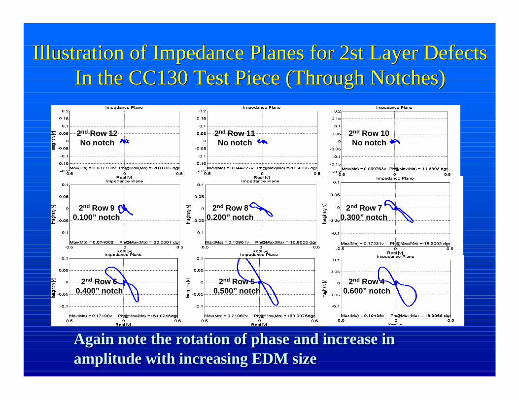
Illustration of Impedance Planes for 2st Layer DefectsIllustration of Impedance Planes for 2st Layer DefectsIn the CC130 Test Piece (Through Notches)In the CC130 Test Piece (Through Notches)
Again note the rotation of phase and increase in amplitude with increasing EDM sizeAgain note the rotation of phase and increase in amplitude with increasing EDM size
Imaginary Component of Impedance Planes for 2nd
Layer Defects in the P3 Test Piece (Corner Notches)Imaginary Component of Impedance Planes for 2nd
Layer Defects in the P3 Test Piece (Corner Notches)
All the EDM notches are the same size. Variances in signals occur to the notch proximity to the 1st and 2nd layer edges. Note the increase in amplitude and increase in slope for the notched. (Driving frequency=1.6kHz)
Imaginary Component of Impedance Planes for 2nd
Layer Defects in the P3 Test Piece (Corner Notches)
Imaginary Component of Impedance Planes for 2nd
Layer Defects in the P3 Test Piece (Corner Notches)
All the EDM notches are the same size. Variances in signals occur to the notch proximity to the 1st and 2nd layer edges. Note the increase in phase angle in impedance plane for the notched. (Driving frequency=0.8kHz)
Imaginary Imaginary Component of Component of
Impedance Planes for Impedance Planes for 1st Row Defects in 1st Row Defects in the F18 Test Piece the F18 Test Piece (Through Notches)(Through Notches)
Imaginary Imaginary Component of Component of
Impedance Planes for Impedance Planes for 2nd Row Defects in 2nd Row Defects in the F18 Test Piece the F18 Test Piece (Through Notches)(Through Notches)
Summary of F18 Test Piece ResultsSummary of F18 Test Piece Results
• EDM notches as small as 0.135” were detected ” in 0.134’ aluminum through 0.750” of composite material with an S/N > 3.
• Test results were influenced by nearby fasteners and the sealant groves (edge effects) in the second layer– Can be overcome by
probe offset or probe enhancements
• EDM notches as small as 0.135” were detected ” in 0.134’ aluminum through 0.750” of composite material with an S/N > 3.
• Test results were influenced by nearby fasteners and the sealant groves (edge effects) in the second layer– Can be overcome by
probe offset or probe enhancements
Recent Trials on the F18 Test PieceRecent Trials on the F18 Test Piece
• Application of reference subtraction variation– Use wavelet method to do the fit every 10 points– For every fitting calculate RMS error– Plot RMS error
• Application of reference subtraction variation– Use wavelet method to do the fit every 10 points– For every fitting calculate RMS error– Plot RMS error
Fastener with no defect: low RMS error
Fastener with 0.120” x 0.200” EDM Notch: large RMS error
Further WorkFurther Work
• For the P3 test pieces– Repeat inspection on test pieces with simulated differential
reflection– Vary the digital filter parameters– Apply methodology to real P3 structure with real defects
• For the CC130 test pieces– Apply methodology to test pieces with 1st and 2nd layer defects
in chordwise direction– Apply methodology test pieces with raised head fasteners– Apply methodology to Lockheed SB92-790 inspections
• For F18 – Trail inspections on F18 wings
Further WorkFurther Work
• Investigate possibility of combining FG_RFEC technology with C-Scan capabilities
• Real time post data analysis
• Investigate possibility of combining FG_RFEC technology with C-Scan capabilities
• Real time post data analysis
ConclusionConclusion
• The FG_RFEC technology has been successfully applied to test pieces representative of thick complex aircraft structures
• Further work is ongoing– New test pieces– On wing trials
• Thank you to Mr Yushi Sun of Innovative Materials Testing Technologies (IMTT) for his assistance to the Canadian Forces ASIP program