19
Aspen Plus IGCC Model Aspen Plus
8/2/2019 Aspen IGCC Model
http://slidepdf.com/reader/full/aspen-igcc-model 1/19
Aspen Plus IGCC Model
Aspen Plus
8/2/2019 Aspen IGCC Model
http://slidepdf.com/reader/full/aspen-igcc-model 2/19
Copyright © 2008-2011 by Aspen Technology, Inc. All rights reserved.
Aspen Plus®, Aspen Properties®, the aspen leaf logo and Plantelligence and Enterprise Optimization are trademarksor registered trademarks of Aspen Technology, Inc., Burlington, MA.
All other brand and product names are trademarks or registered trademarks of their respective companies.
This document is intended as a guide to using AspenTech's software. This documentation contains AspenTechproprietary and confidential information and may not be disclosed, used, or copied without the prior consent of AspenTech or as set forth in the applicable license agreement. Users are solely responsible for the proper use of the software and the application of the results obtained.
Although AspenTech has tested the software and reviewed the documentation, the sole warranty for the software
may be found in the applicable license agreement between AspenTech and the user. ASPENTECH MAKES NOWARRANTY OR REPRESENTATION, EITHER EXPRESSED OR IMPLIED, WITH RESPECT TO THIS DOCUMENTATION,ITS QUALITY, PERFORMANCE, MERCHANTABILITY, OR FITNESS FOR A PARTICULAR PURPOSE.
Aspen Technology, Inc.200 Wheeler RoadBurlington, MA 01803-5501USA
Phone: (1) (781) 221-6400Toll Free: (1) (888) 996-7100URL: http://www.aspentech.com
8/2/2019 Aspen IGCC Model
http://slidepdf.com/reader/full/aspen-igcc-model 3/19
Contents iii
Contents1 Introduction.........................................................................................................1
2 Components .........................................................................................................2
3 Process Description..............................................................................................4
4 Physical Properties...............................................................................................6
5 Chemical Reactions ..............................................................................................7
Coal Gasification ..............................................................................................7Desulfuration...................................................................................................8
Power Generation.............................................................................................8WGS...............................................................................................................8
Methanation ....................................................................................................9
6 Simulation Approaches.......................................................................................10
7 Simulation Results .............................................................................................13
8 Conclusions ........................................................................................................15

8/2/2019 Aspen IGCC Model
http://slidepdf.com/reader/full/aspen-igcc-model 4/19
8/2/2019 Aspen IGCC Model
http://slidepdf.com/reader/full/aspen-igcc-model 5/19
1 Introduction 1
1 Introduction
Global warming and global politics are driving the US and other countriestowards the development of new energy technologies which avoid the use of
petroleum and which allow for carbon capture and sequestration.
This model simulates an Integrated Coal Gasification Combined-Cycle Power
(IGCC) process with different sections of the plant modeled as hierarchy
blocks (model templates).
The model includes the following sections:
Sizing of the coal
Gasification unit
Air Separation (ASU)
Gas cleaning unit
Water-gas shift unit
Ammonia unit
Methanizer
Combined cycle power generation
8/2/2019 Aspen IGCC Model
http://slidepdf.com/reader/full/aspen-igcc-model 6/19
2 2 Components
2 Components
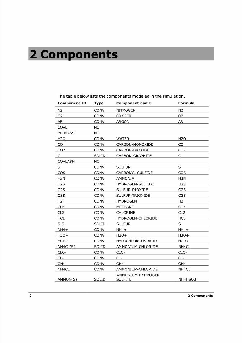
The table below lists the components modeled in the simulation.
Component ID Type Component name Formula
N2 CONV NITROGEN N2
O2 CONV OXYGEN O2
AR CONV ARGON AR
COAL NC
BIOMASS NC
H2O CONV WATER H2O
CO CONV CARBON-MONOXIDE CO
CO2 CONV CARBON-DIOXIDE CO2
C SOLID CARBON-GRAPHITE C
COALASH NC
S CONV SULFUR S
COS CONV CARBONYL-SULFIDE COS
H3N CONV AMMONIA H3NH2S CONV HYDROGEN-SULFIDE H2S
O2S CONV SULFUR-DIOXIDE O2S
O3S CONV SULFUR-TRIOXIDE O3S
H2 CONV HYDROGEN H2
CH4 CONV METHANE CH4
CL2 CONV CHLORINE CL2
HCL CONV HYDROGEN-CHLORIDE HCL
S-S SOLID SULFUR S
NH4+ CONV NH4+ NH4+
H3O+ CONV H3O+ H3O+
HCLO CONV HYPOCHLOROUS-ACID HCLO
NH4CL(S) SOLID AMMONIUM-CHLORIDE NH4CL
CLO- CONV CLO- CLO-
CL- CONV CL- CL-
OH- CONV OH- OH-
NH4CL CONV AMMONIUM-CHLORIDE NH4CL
AMMON(S) SOLIDAMMONIUM-HYDROGEN-SULFITE NH4HSO3
8/2/2019 Aspen IGCC Model
http://slidepdf.com/reader/full/aspen-igcc-model 7/19
2 Components 3
Component ID Type Component name Formula
NH4HS(S) SOLIDAMMONIUM-HYDROGEN-SULFIDE NH4HS
SALT1 SOLID AMMONIUM-SULFITE-HYDRATE (NH4)2SO3*W
SALT2 SOLID AMMONIUM-SULFITE (NH4)2SO3
HSO3- CONV HSO3- HSO3-
HS- CONV HS- HS-
SO3-- CONV SO3-- SO3-2
S-- CONV S-- S-2
S2 CONV SULFUR-DIATOMIC-GAS S2
S3 CONV SULFUR-TRIATOMIC-GAS S3
S4 CONV SULFUR-4-ATOMIC-GAS S4
S5 CONV SULFUR-5-ATOMIC-GAS S5
S6 CONV SULFUR-6-ATOMIC-GAS S6
S7 CONV SULFUR-7-ATOMIC-GAS S7
S8 CONV SULFUR-8-ATOMIC-GAS S8MEOH CONV METHANOL CH4O
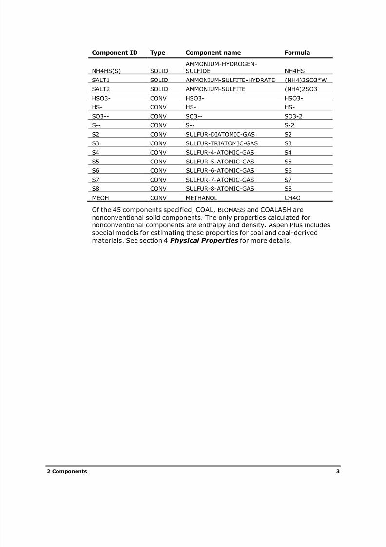
Of the 45 components specified, COAL, BIOMASS and COALASH are
nonconventional solid components. The only properties calculated fornonconventional components are enthalpy and density. Aspen Plus includes
special models for estimating these properties for coal and coal-derived
materials. See section 4 Physical Properties for more details.
8/2/2019 Aspen IGCC Model
http://slidepdf.com/reader/full/aspen-igcc-model 8/19
4
3 Process
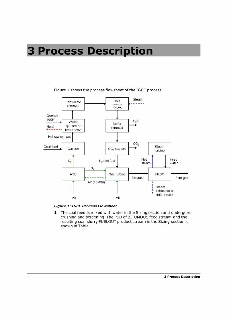
Figure 1 shows t
Figure 1: IGCC P
1 The coal feed
crushing and
resulting coal
shown in Tab
3 P
Description
e process flowsheet of the IGCC process.
ocess Flowsheet
is mixed with water in the Sizing section and
screening. The PSD of BITUMOUS feed strea
slurry FUELOUT product stream in the Sizing
le 1.
rocess Description
undergoes
and the
section is
8/2/2019 Aspen IGCC Model
http://slidepdf.com/reader/full/aspen-igcc-model 9/19
3 Process Description 5
Table 1
IntervalLowerlimit Upper limit
Weight fraction inBITUMOUS
Weight fractionin FUELOUT
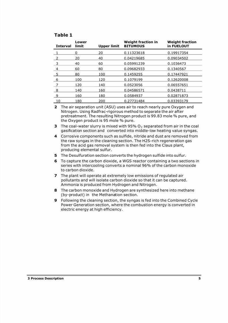
1 0 20 0.11323618 0.19917354
2 20 40 0.04219685 0.09034502
3 40 60 0.05991239 0.1036473
4 60 80 0.09682933 0.1340567
5 80 100 0.1459255 0.17447921
6 100 120 0.1079199 0.12620008
7 120 140 0.0523056 0.06557651
8 140 160 0.04586571 0.0438711
9 160 180 0.0584937 0.02871873
10 180 200 0.27731484 0.03393179
2 The air separation unit (ASU) uses air to reach nearly pure Oxygen and
Nitrogen. Using Radfrac-rigorous method to separate the air afterpretreatment. The resulting Nitrogen product is 99.83 mole % pure, and
the Oxygen product is 95 mole % pure.
3 The coal-water slurry is mixed with 95% O2 separated from air in the coalgasification section and converted into middle-low heating value syngas.
4 Corrosive components such as sulfide, nitride and dust are removed from
the raw syngas in the cleaning section. The H2S-rich regeneration gasfrom the acid gas removal system is then fed into the Claus plant,producing elemental sulfur.
5 The Desulfuration section converts the hydrogen sulfide into sulfur.
6 To capture the carbon dioxide, a WGS reactor containing a two sections inseries with intercooling converts a nominal 96% of the carbon monoxide
to carbon dioxide.7 The plant will operate at extremely low emissions of regulated air
pollutants and will isolate carbon dioxide so that it can be captured.
Ammonia is produced from Hydrogen and Nitrogen.
8 The carbon monoxide and Hydrogen are synthesized here into methane(by-product) in the Methanation section.
9 Following the cleaning section, the syngas is fed into the Combined CyclePower Generation section, where the combustion energy is converted in
electric energy at high efficiency.
8/2/2019 Aspen IGCC Model
http://slidepdf.com/reader/full/aspen-igcc-model 10/19
6 4 Physical Properties
4 Physical Properties
The global property method used in this model is Peng-Rob. This method isused for the gasification and downstream unit operations. The SOLIDS
property method is used for the coal crushing and screening section. TheIDEAL property method is used in the CLAUS Hierarchy (Desulfuration
section). The BWRS property method is used in the NH3 Hierarchy (the
previous step of Methanation). The PR-BM property method is used in thePower Generation section.
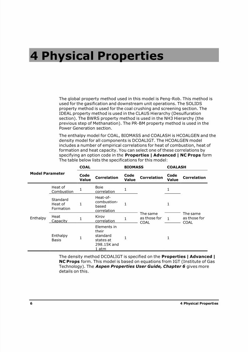
The enthalpy model for COAL, BIOMASS and COALASH is HCOALGEN and the
density model for all components is DCOALIGT. The HCOALGEN modelincludes a number of empirical correlations for heat of combustion, heat of formation and heat capacity. You can select one of these correlations by
specifying an option code in the Properties | Advanced | NC Props form
The table below lists the specifications for this model:
Model Parameter
COAL BIOMASS COALASH
CodeValue
CorrelationCodeValue
CorrelationCodeValue
Correlation
Enthalpy
Heat of Combustion
1Boiecorrelation
1
The sameas those forCOAL
1
The sameas those forCOAL
StandardHeat of
Formation
1
Heat-of-combustion-basedcorrelation
1 1
HeatCapacity
1Kirovcorrelation
1 1
EnthalpyBasis
1
Elements intheirstandardstates at
298.15K and1 atm
1 1
The density method DCOALIGT is specified on the Properties | Advanced |
NC Props form. This model is based on equations from IGT (Institute of Gas
Technology). The Aspen Properties User Guide, Chapter 6 gives moredetails on this.
8/2/2019 Aspen IGCC Model
http://slidepdf.com/reader/full/aspen-igcc-model 11/19
5 Chemical Reactions 7
5 Chemical Reactions
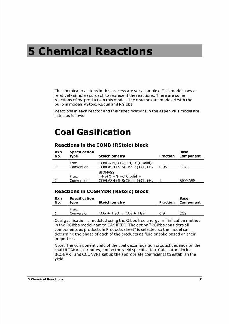
The chemical reactions in this process are very complex. This model uses arelatively simple approach to represent the reactions. There are some
reactions of by-products in this model. The reactors are modeled with thebuilt-in models RStoic, REquil and RGibbs.
Reactions in each reactor and their specifications in the Aspen Plus model are
listed as follows:
Coal Gasification
Reactions in the COMB (RStoic) block
RxnNo.
Specificationtype Stoichiometry Fraction
BaseComponent
1Frac.Conversion
COAL H2O+O2+N2+C(Cisolid)+
COALASH+S-S(Cisolid)+CL2+H2 0.95 COAL
2Frac.Conversion
BIOMASSH2+O2+N2+C(Cisolid)+
COALASH+S-S(Cisolid)+CL2+H2 1 BIOMASS
Reactions in COSHYDR (RStoic) block
RxnNo.
Specificationtype Stoichiometry Fraction
BaseComponent
1Frac.Conversion COS + H2O CO2 + H2S 0.9 COS
Coal gasification is modeled using the Gibbs free energy minimization method
in the RGibbs model named GASIFIER. The option “RGibbs considers allcomponents as products in Products sheet” is selected so the model can
determine the phase of each of the products as fluid or solid based on their
properties.
Note: The component yield of the coal decomposition product depends on the
coal ULTANAL attributes, not on the yield specification. Calculator blocksBCONVRT and CCONVRT set up the appropriate coefficients to establish the
yield.
8/2/2019 Aspen IGCC Model
http://slidepdf.com/reader/full/aspen-igcc-model 12/19
8 5 Chemical Reactions
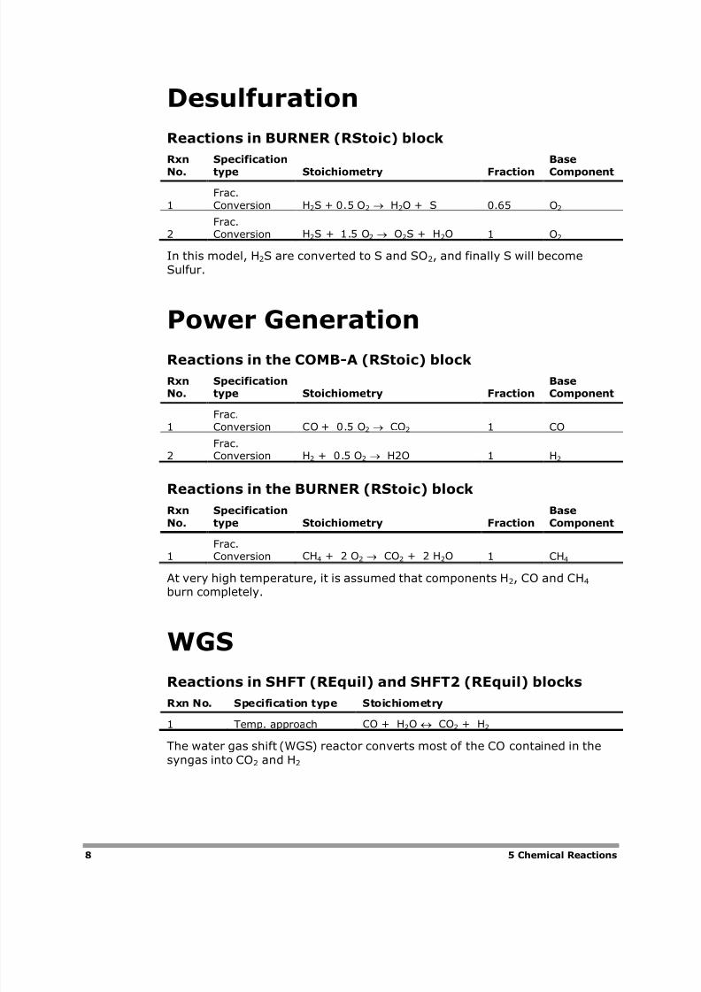
Desulfuration
Reactions in BURNER (RStoic) block
Rxn
No.
Specification
type Stoichiometry Fraction
Base
Component
1Frac.Conversion H2S + 0.5 O2 H2O + S 0.65 O2
2Frac.Conversion H2S + 1.5 O2 O2S + H2O 1 O2
In this model, H2S are converted to S and SO2, and finally S will become
Sulfur.
Power Generation
Reactions in the COMB-A (RStoic) block
RxnNo.
Specificationtype Stoichiometry Fraction
BaseComponent
1Frac.Conversion CO + 0.5 O2 CO2 1 CO
2Frac.Conversion H2 + 0.5 O2 H2O 1 H2
Reactions in the BURNER (RStoic) block
Rxn
No.
Specification
type Stoichiometry Fraction
Base
Component
1Frac.Conversion CH4 + 2 O2 CO2 + 2 H2O 1 CH4
At very high temperature, it is assumed that components H2, CO and CH4
burn completely.
WGS
Reactions in SHFT (REquil) and SHFT2 (REquil) blocks
Rxn No. Specification type Stoichiometry
1 Temp. approach CO + H2O CO2 + H2
The water gas shift (WGS) reactor converts most of the CO contained in the
syngas into CO2 and H2
8/2/2019 Aspen IGCC Model
http://slidepdf.com/reader/full/aspen-igcc-model 13/19
5 Chemical Reactions 9
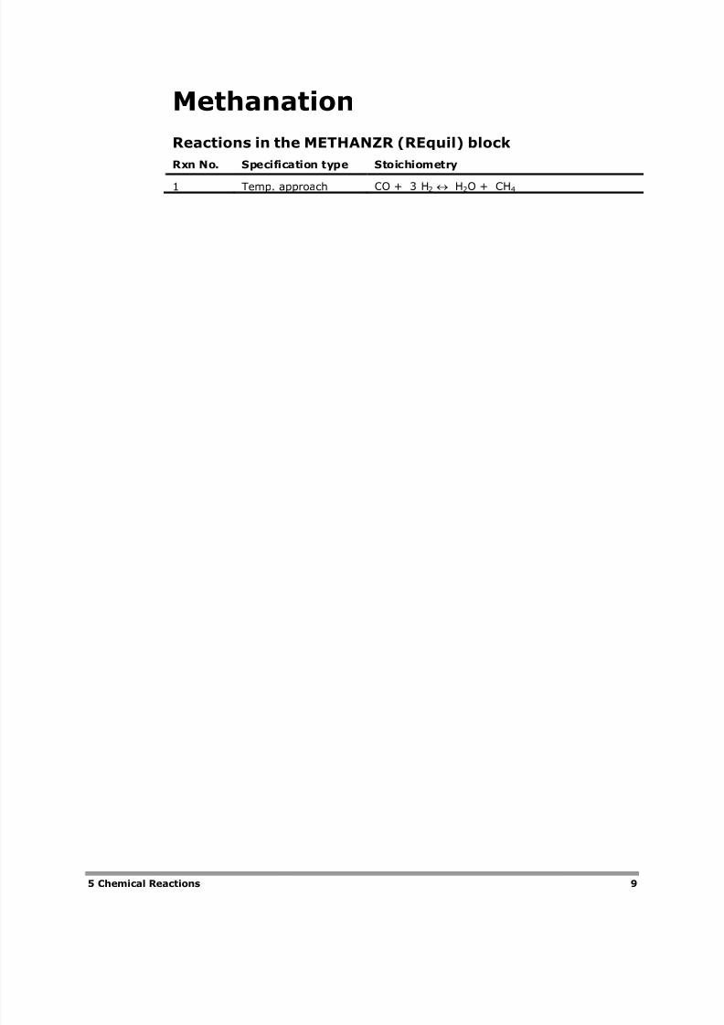
Methanation
Reactions in the METHANZR (REquil) block
Rxn No. Specification type Stoichiometry
1 Temp. approach CO + 3 H2 H2O + CH4
8/2/2019 Aspen IGCC Model
http://slidepdf.com/reader/full/aspen-igcc-model 14/19
10 6 Simulation Approaches
6 Simulation Approaches
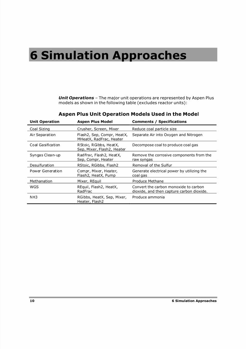
Unit Operations – The major unit operations are represented by Aspen Plusmodels as shown in the following table (excludes reactor units):
Aspen Plus Unit Operation Models Used in the Model
Unit Operation Aspen Plus Model Comments / Specifications
Coal Sizing Crusher, Screen, Mixer Reduce coal particle size
Air Separation Flash2, Sep, Compr, HeatX,MHeatX, RadFrac, Heater
Separate Air into Oxygen and Nitrogen
Coal Gasification RStoic, RGibbs, HeatX,Sep, Mixer, Flash2, Heater
Decompose coal to produce coal gas
Syngas Clean-up RadFrac, Flash2, HeatX,Sep, Compr, Heater
Remove the corrosive components from theraw syngas
Desulfuration RStoic, RGibbs, Flash2 Removal of the Sulfur
Power Generation Compr, Mixer, Heater,Flash2, HeatX, Pump
Generate electrical power by utilizing thecoal gas
Methanation Mixer, REquil Produce Methane
WGS REquil, Flash2, HeatX,RadFrac
Convert the carbon monoxide to carbondioxide, and then capture carbon dioxide.
NH3 RGibbs, HeatX, Sep, Mixer,Heater, Flash2
Produce ammonia
8/2/2019 Aspen IGCC Model
http://slidepdf.com/reader/full/aspen-igcc-model 15/19
6 Simulation Approaches 11
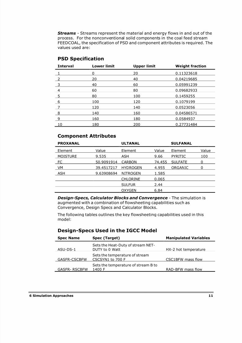
Streams - Streams represent the material and energy flows in and out of the
process. For the nonconventional solid components in the coal feed stream
FEEDCOAL, the specification of PSD and component attributes is required. Thevalues used are:
PSD SpecificationInterval Lower limit Upper limit Weight fraction
1 0 20 0.11323618
2 20 40 0.04219685
3 40 60 0.05991239
4 60 80 0.09682933
5 80 100 0.1459255
6 100 120 0.1079199
7 120 140 0.0523056
8 140 160 0.04586571
9 160 180 0.058493710 180 200 0.27731484
Component Attributes
PROXANAL ULTANAL SULFANAL
Element Value Element Value Element Value
MOISTURE 9.535 ASH 9.66 PYRITIC 100
FC 50.9091914 CARBON 74.455 SULFATE 0
VM 39.4517217 HYDROGEN 4.955 ORGANIC 0
ASH 9.63908694 NITROGEN 1.585
CHLORINE 0.065SULFUR 2.44
OXYGEN 6.84
Design-Specs, Calculator Blocks and Convergence - The simulation isaugmented with a combination of flowsheeting capabilities such as
Convergence, Design Specs and Calculator Blocks.
The following tables outlines the key flowsheeting capabilities used in thismodel:
Design-Specs Used in the IGCC Model
Spec Name Spec (Target) Manipulated Variables
ASU-DS-1Sets the Heat-Duty of stream NET-DUTY to 0 Watt HX-2 hot temperature
GASFR-CSCBFWSets the temperature of streamCSCSYN1 to 700 F CSC1BFW mass flow
GASFR- RSCBFWSets the temperature of stream B to1400 F RAD-BFW mass flow
8/2/2019 Aspen IGCC Model
http://slidepdf.com/reader/full/aspen-igcc-model 16/19
12 6 Simulation Approaches
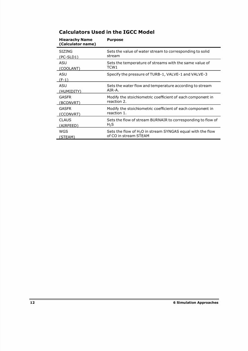
Calculators Used in the IGCC Model
Hiearachy Name(Calculator name)
Purpose
SIZING
(PC-SLD1)
Sets the value of water stream to corresponding to solidstream
ASU
(COOLANT)
Sets the temperature of streams with the same value of TCW1
ASU
(F-1)
Specify the pressure of TURB-1, VALVE-1 and VALVE-3
ASU
(HUMIDITY)
Sets the water flow and temperature according to streamAIR-A.
GASFR
(BCONVRT)
Modify the stoichiometric coefficient of each component inreaction 2.
GASFR
(CCONVRT)
Modify the stoichiometric coefficient of each component inreaction 1.
CLAUS
(AIRFEED)
Sets the flow of stream BURNAIR to corresponding to flow of
H2S
WGS
(STEAM)
Sets the flow of H2O in stream SYNGAS equal with the flowof CO in stream STEAM
8/2/2019 Aspen IGCC Model
http://slidepdf.com/reader/full/aspen-igcc-model 17/19
7 Simulation Results 13
7 Simulation Results
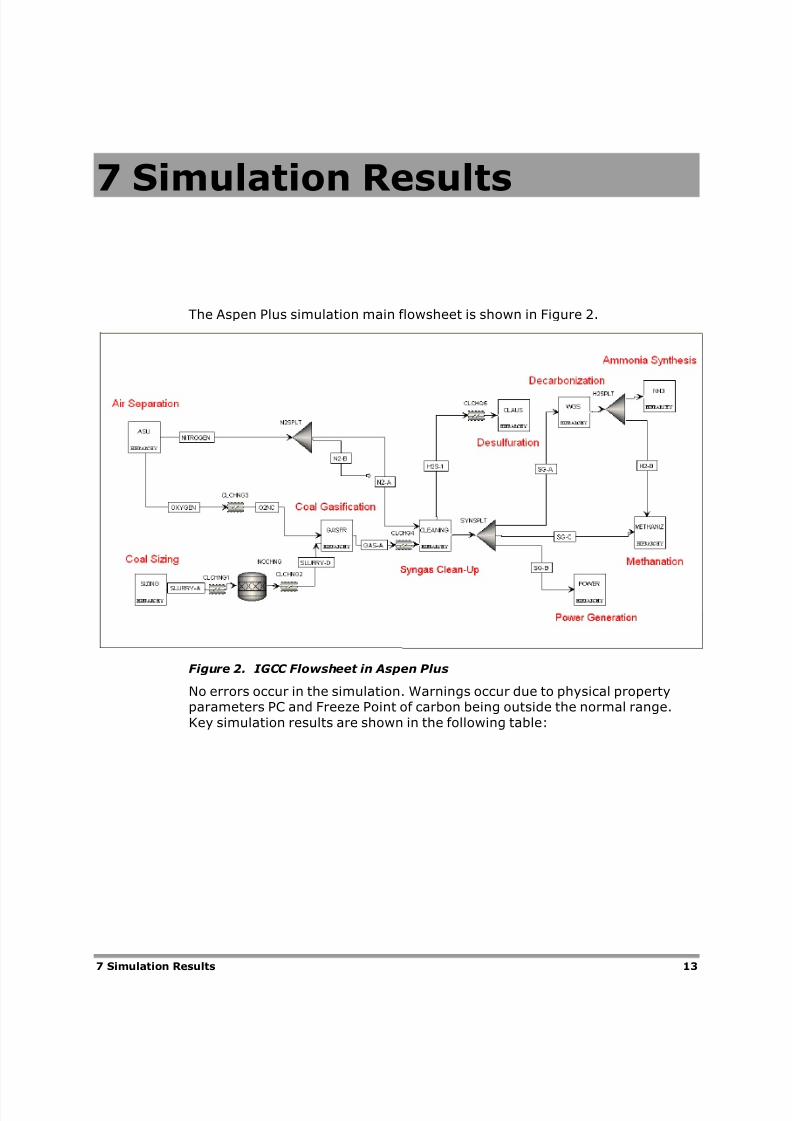
The Aspen Plus simulation main flowsheet is shown in Figure 2.
Figure 2. IGCC Flowsheet in Aspen Plus
No errors occur in the simulation. Warnings occur due to physical propertyparameters PC and Freeze Point of carbon being outside the normal range.
Key simulation results are shown in the following table:
8/2/2019 Aspen IGCC Model
http://slidepdf.com/reader/full/aspen-igcc-model 18/19
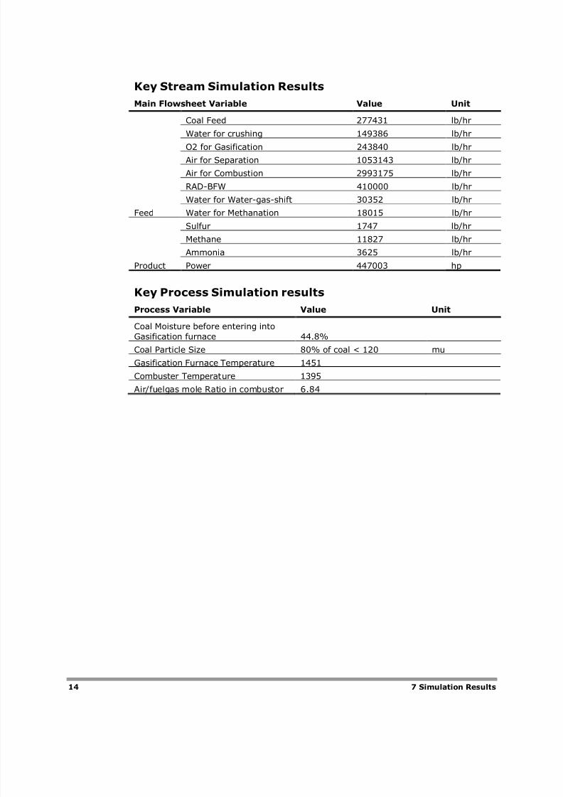
14 7 Simulation Results
Key Stream Simulation Results
Main Flowsheet Variable Value Unit
Feed
Coal Feed 277431 lb/hr
Water for crushing 149386 lb/hr
O2 for Gasification 243840 lb/hr
Air for Separation 1053143 lb/hr
Air for Combustion 2993175 lb/hr
RAD-BFW 410000 lb/hr
Water for Water-gas-shift 30352 lb/hr
Water for Methanation 18015 lb/hr
Product
Sulfur 1747 lb/hr
Methane 11827 lb/hr
Ammonia 3625 lb/hr
Power 447003 hp
Key Process Simulation results
Process Variable Value Unit
Coal Moisture before entering into
Gasification furnace 44.8%
Coal Particle Size 80% of coal < 120 mu
Gasification Furnace Temperature 1451
Combuster Temperature 1395
Air/fuelgas mole Ratio in combustor 6.84
8/2/2019 Aspen IGCC Model
http://slidepdf.com/reader/full/aspen-igcc-model 19/19
8 Conclusions
The IGCC model provides a useful description of the process. The simulationtakes advantage of Aspen Plus’s capabilities for modeling solid components.
This includes tracking component attributes and particle size distribution, andestimating properties for coal. It also produces Methane, Sulfur and Ammonia
as by-products.
The model may be used as a guide for understanding the process and theeconomics, and also as a starting point for more sophisticated models for
plant design and specifying process equipment.


