21
COMMUNICATIONS 6.3m and 7.5m Receive-Only Earth Station Assembly Manual Standard 7.5 Meter Depicted with Optional Motorization Kit Rev. 2016.04.01 Subject to change without notice.
COMMUNICATIONS
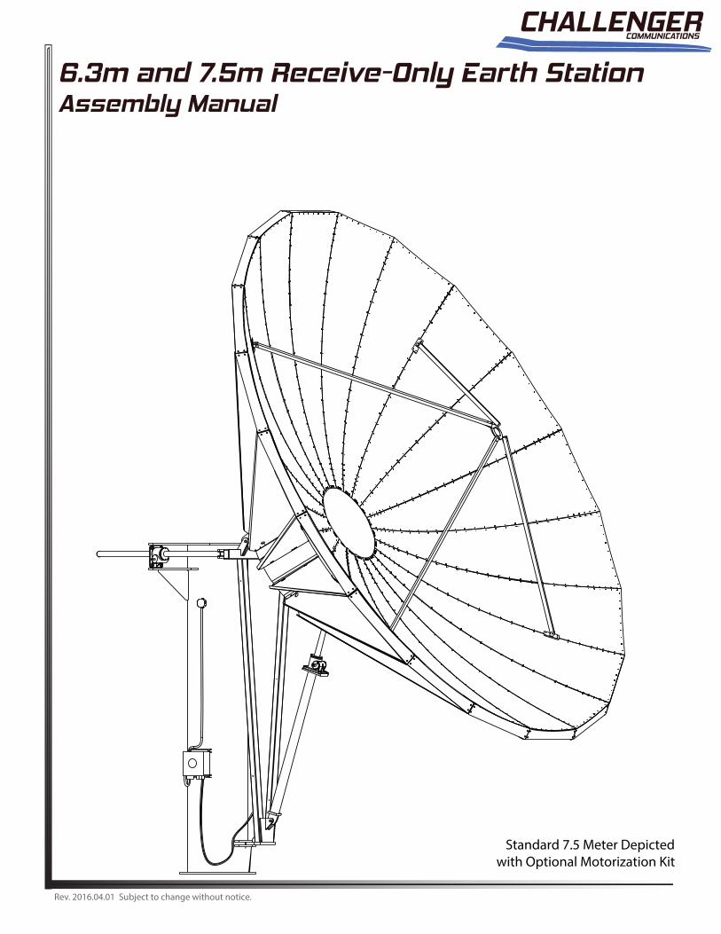
6.3m and 7.5m Receive-Only Earth StationAssembly Manual
Standard 7.5 Meter Depictedwith Optional Motorization Kit
Rev. 2016.04.01 Subject to change without notice.

This CHALLENGER COMMUNICATIONS, LLC ("CHALLENGER") equipment is warranted to be free from defects in material and workmanship under normal use and service. CHALLENGER shall repair or replace defective equipment, at no charge, or at its option, refund the purchase price, if the equipment is returned to CHALLENGER not more than twelve (12) months after shipment. Removal or reinstallation of equipment and its transportation shall not be at cost of CHALLENGER except CHALLENGER shall return repaired or replaced equipment freight prepaid.
This Warranty shall not apply to equipment which has been repaired or altered in any way so as to a�ect its stability or durability, or which has been subject to misuse, negligence or accident. This Warranty does not cover equipment which has been impaired by severe weather conditions such as excessive wind, ice, storms, lightning, or other natural occurrences over which CHALLENGER has no control, and this Warranty shall not apply to equipment which has been operated or installed other than in accordance with the instructions furnished by CHALLENGER.
Claimants under this Warranty shall present their claims along with the defective equipment to CHALLENGER immediately upon failure. Noncompliance with any part of this claim procedure may invalidate this warranty in whole or in part.
THIS WARRANTY IS EXPRESSLY IN LIEU OF ALL OTHER AGREEMENTS AND WARRANTIES, ANY IMPLIED WARRANTY OF MERCHANTABILITY OR FITNESS FOR A PARTICULAR PURPOSE IS LIMITED IN DURATION TO THE DURATION OF THIS WARRANTY. CHALLENGER DOES NOT AUTHORIZE ANY PERSON TO ASSUME FOR IT THE OBLIGATIONS CONTAINED IN THIS WARRANTY AND CHALLENGER COMMUNICATIONS NEITHER ASSUMES NOR AUTHORIZES ANY REPRESENTATIVEOR OTHER PERSON TO ASSUME FOR IT ANY OTHER LIABILITY IN CONNECTION WITH THE EQUIPMENT DELIVERED ORPROVIDED.
IN NO EVENT SHALL CHALLENGER BE LIABLE FOR ANY LOSS OF PROFITS, LOSS OF USE, INTERRUPTION OF BUSINESS, OR INDIRECT, SPECIAL OR CONSEQUENTIAL DAMAGES OF ANY KIND.
In no event shall CHALLENGER be liable for damages in an amount greater than the purchase price of the equipment.
Some states do not allow limitations on how long an implied warranty lasts, or allow the exclusion or limitation of incidental or consequential damages, so the above limitations or exclusions may not apply to you.
CHALLENGER has the right to void the warranty when the antenna is installed by someone other then a certi�ed installer.
COMMUNICATIONS
Product Serial Number: _____________________________
Date Purchased: __________________________________Challenger Communications704 North Clark StreetAlbion, Michigan 49224 USATel: (01) 517 680 0125Fax: (01) 517 680 0133info@challengercommunications.comwww.ChallengerCommunications.com 2

3
1. Perform as many functions as possible on the ground.
2. Watch out for overhead power lines. Check the distance to the power lines before starting installation. We recommend you stay a minimum of 6 meters (20 feet) from all power lines.
3. Do not use metal ladders.
4. Do not install antenna or mast assembly on a windy day.
5. If you start to drop antenna or mast assembly, get away from it and let if fall.
6. If any part of the antenna or mast assembly comes in contact with a power line, call your local power company. DO NOT TRY TO REMOVE IT YOURSELF! They will remove it safely. 7. Make sure that the mast assembly is properly grounded. WARNINGAssembling dish antennas on windy days can be dangerous. Because of the antenna surface, even slight winds create strong forces. For example, a 1.0m antenna facing a wind of 32 km/h (20 mph) can undergo forces of 269 N (60 lbs.). Be prepared to safely handle these forces at unexpected moments. Do not at-tempt to assemble, move or mount dish on windy days or serious, even fatal accidents may occur. CHALLENGER COMMUNICATIONS is not responsible or liable for damage or injury resulting fromantenna installations.
WARNING
INSTALLATION OF THIS PRODUCT SHOULD BE PERFORMED ONLY BY A PROFESSIONAL INSTALLER AND IS NOT RECOMMENDED FOR CONSUMER D.I.Y. (DO-IT-YOURSELF) INSTALLATIONS.
IMPORTANT!!!
WATCH FOR WIRES! Installation of this product near power lines is dangerous. For your own safety, follow these important safety rules.
Antennas improperly installed or installed to an inadequate structure are very susceptible to wind damage. This damage can be very serious or even life threatening. The owner and installer assumes full responsibility that the installation is structurally sound to support all loads (weight, wind & ice) and properly sealed against leaks. CHALLENGER COMMUNICATIONS will not accept liability for any damage caused by a satellite system due to the many unknown variable applications.
RECOMMENDATIONCHALLENGER COMMUNICATIONS highly recommends the application of anti-seize wax on all antenna and mount hardware upon installation.
4
Unpacking and Inspection
Shipping cartons should be unpacked and contents checked for damaged or missing parts. Should there be any parts thatare damaged or missing, please contact technical support for replacement.
Site Selection
The main objective of conducting a site survey utilizing a compass and inclinometer is to choose a mounting location on theground that will give you the greatest amount of swing for azimuth and elevation for present as well as future use. A thoroughpre-installation site survey is strongly recommended because it can alert you to any “look angle”, soil, wind or otherproblems.
The first and most important consideration when choosing a prospective antenna site is whether or not the area can providean acceptable “look angle” to the satellite. A site with a clear, unobstructed view facing south, southeast is required. Yourantenna site must be selected in advance so that you will be able to receive the strongest signal available. Also considerobstructions that may occur in the future such as the growth of trees.
It is important to conduct an on-site survey with a portable antenna or with a compass and clinometer to avoid interference,obstructions, etc.
When selecting “look angle,” be sure to observe and take readings approximately 10 deg to the left and right, above andbelow your selected “look angle.”
Before Ground Pole Installation, the soil type should be checked because soil conditions vary widely in composition andload bearing capacity. A soil check will help you to determine the typeand size of foundation required to provide a stable base for the antenna.
Before digging is done, information regarding the possibility of underground telephone lines, power lines, storm drains, etc.,in the excavation area should be obtained from the appropriate agency.
As with any other type of construction, a local building permit may be required before installing an antenna. It is the propertyowner’s responsibility to obtain any and all permits. Ground mounts are certified for 125 mph wind survival.
Introduction
Thank you for purchasing your Challenger Communications product. We trust that you will �nd this to be awell designed product that will proved many years of reliable service. Please read this manual thoroughly before beginning assembly. For best results in the assembly process, perform each step in the same sequence as listed in this manual. Record the serial number of the unit on to page two for future referance and read the warranty information. The serial number plate can be found on the hub.
5
2
567
1
43
9
8
10
11
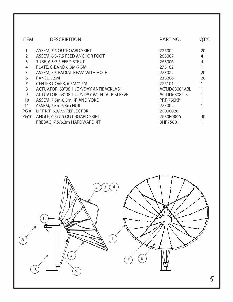
ITEM DESCRIPITION PART NO. QTY.
1 ASSEM, 7.5 OUTBOARD SKIRT 275004 20 2 ASSEM, 6.3/7.5 FEED ANCHOR FOOT 263007 4 3 TUBE, 6.3/7.5 FEED STRUT 263006 4 4 PLATE, C-BAND 6.3M/7.5M 275102 1 5 ASSEM, 7.5 RADIAL BEAM WITH HOLE 275022 20 6 PANEL, 7.5M 238206 20 7 CENTER COVER, 6.3M/7.5M 275101 1 8 ACTUATOR, 63”08:1 JOY/DAY ANTIBACKLASH ACTJD63081ABL 1 9 ACTUATOR, 63”08:1 JOY/DAY WITH JACK SLEEVE ACTJD63081JS 1 10 ASSEM, 7.5m-6.3m KP AND YOKE PRT-750KP 1 11 ASSEM, 7.5m 6.3m HUB 275002 1 PG 8 LIFT KIT, 6.3/7.5 REFLECTOR 20000026 1 PG10 ANGLE, 6.3/7.5 OUT BOARD SKIRT 2630P0006 40 PREBAG, 7.5/6.3m HARDWARE KIT 3HP75001 1
6
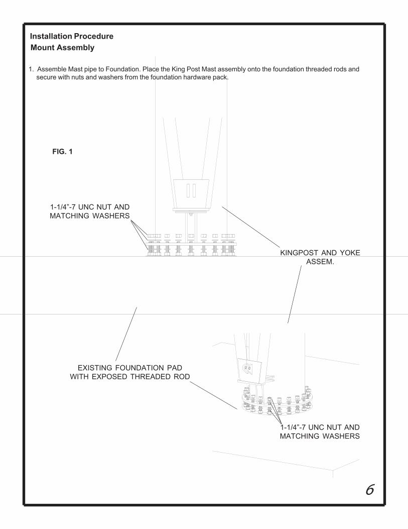
Installation ProcedureMount Assembly
FIG. 1
1. Assemble Mast pipe to Foundation. Place the King Post Mast assembly onto the foundation threaded rods and secure with nuts and washers from the foundation hardware pack.
EXISTING FOUNDATION PADWITH EXPOSED THREADED ROD
KINGPOST AND YOKEASSEM.
1-1/4”-7 UNC NUT ANDMATCHING WASHERS
1-1/4”-7 UNC NUT ANDMATCHING WASHERS
7
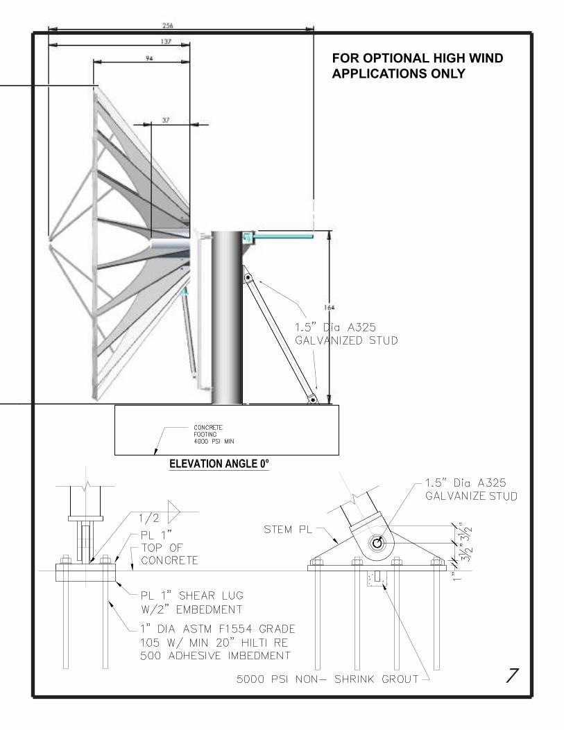
FOR OPTIONAL HIGH WIND APPLICATIONS ONLY

8
One wof
20000027ROD, TAPPED 1 X 3.5
20000034CAP, ROD 2X2X1/8 ALUM
Place one washer on either side of lower detail
Elevation Drive Assembly
1) Attach Elevation Drive Assembly (prt# PRT-ACTJD63081JS ACTUATOR, 63”08:1 JOY/DAY W/JACK SLV) as pictured below.
2) Use spacer washers to bridge any gap between Yoke Details and Jack Housing Detail.
9
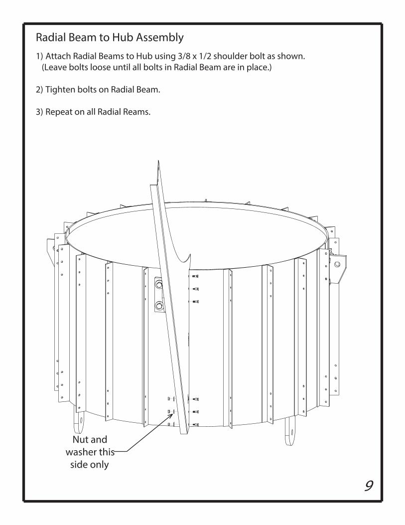
Nut and washer this
side only
1) Attach Radial Beams to Hub using 3/8 x 1/2 shoulder bolt as shown. (Leave bolts loose until all bolts in Radial Beam are in place.)
2) Tighten bolts on Radial Beam.
3) Repeat on all Radial Reams.
Radial Beam to Hub Assembly
10
g
AREA SHOWN INDETAIL
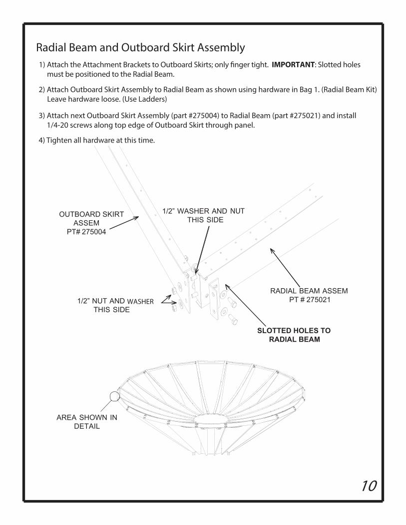
RADIAL BEAM ASSEMPT # 275021
1/2” WASHER AND BOLTTHIS SIDE
1/2” NUT AND BOLTTHIS SIDE
OUTBOARD SKIRT ASSEM
PT# 275004
WASHER
NUT
Radial Beam and Outboard Skirt Assembly
2) Attach Outboard Skirt Assembly to Radial Beam as shown using hardware in Bag 1. (Radial Beam Kit) Leave hardware loose. (Use Ladders)
3) Attach next Outboard Skirt Assembly (part #275004) to Radial Beam (part #275021) and install1/4-20 screws along top edge of Outboard Skirt through panel.
4) Tighten all hardware at this time.
SLOTTED HOLES TORADIAL BEAM
1) IMPORTANT: Slotted holes must be positioned to the Radial Beam.
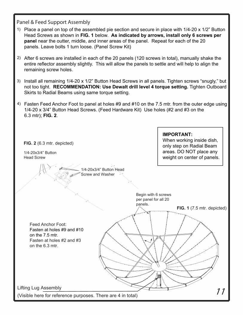
11Lifting Lug Assembly(Visible here for reference purposes. There are 4 in total)
1/4-20x1/2” ButtonHead Screw
1/4-20x3/4” Button HeadScrew and Washer
FIG. 1 (6.3 mtr. depicted)
FIG. 1 (7.5 mtr. depicted)
Place a panel on top of the assembled pie section and secure in place with 1/4-20 x 1/2” ButtonHead Screws as shown in FIG. 1 below. As indicated by arrows, install only 6 screws per panel near the outter, middle, and inner areas of the panel. Repeat for each of the 20 panels. Leave bolts 1 turn loose. (Panel Screw Kit)
After 6 screws are installed in each of the 20 panels (120 screws in total), manually shake the entire reflector assembly slightly. This will allow the panels to settle and will help to align the remaining screw holes.
Install all remaining 1/4-20 x 1/2” Button Head Screws in all panels. Tighten screws “snugly,” but not too tight. RECOMMENDATION: Use Dewalt drill level 4 torque setting. Tighten OutboardSkirts to Radial Beams using same torque setting.
Fasten Feed Anchor Foot to panel at holes #9 and #10 on the 7.5 mtr. from the outer edge using 1/4-20 x 3/4” Button Head Screws. (Feed Hardware Kit) Use holes (#2 and #3 on the 6.3 mtr); FIG. 2.
Panel & Feed Support Assembly
1/4-20x3/4” ButtonHead Screw
FIG. 2 (6.3 mtr. depicted)
Feed Anchor Foot:Fasten at holes #9 and #10on the 7.5 mtr.Fasten at holes #2 and #3on the 6.3 mtr.
1)
Begin with 6 screwsper panel for all 20panels.
IMPORTANT:When working inside dish,only step on Radial Beamareas. DO NOT place anyweight on center of panels.
2)
3)
4)
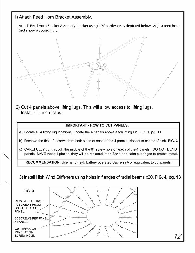
FIG. 3 FIG. 3
12
1) Attach Feed Horn Bracket Assembly.
Attach Feed Horn Bracket Assembly bracket using 1/4” hardware as depicted below. Adjust feed horn(not shown) accordingly.
IMPORTANT - HOW TO CUT PANELS:
a) Locate all 4 lifting lug locations. Locate the 4 panels above each lifting lug. FIG. 1, pg. 11
b) Remove the first 10 screws from both sides of each of the 4 panels, closest to center of dish. FIG. 3
c) CAREFULLY cut through the middle of the 6th screw hole on each of the 4 panels. DO NOT BEND panels SAVE these 4 pieces, they will be replaced later. Sand and paint cut edges to protect metal. RECOMMENDATION: Use hand-held, battery operated Sabre saw or equivalent to cut panels.
3) Install High Wind Stiffeners using holes in flanges of radial beams x20. FIG. 4, pg. 13
2) Cut 4 panels above lifting lugs. This will allow access to lifting lugs. Install 4 lifting straps:
ANEL.
REMOVE THE FIRST10 SCREWS FROMBOTH SIDES OFPANEL.
20 SCREWS PER P4 PANELS.
CUT THROUGHPANEL AT 6thSCREW HOLE.
FIG. 3
12
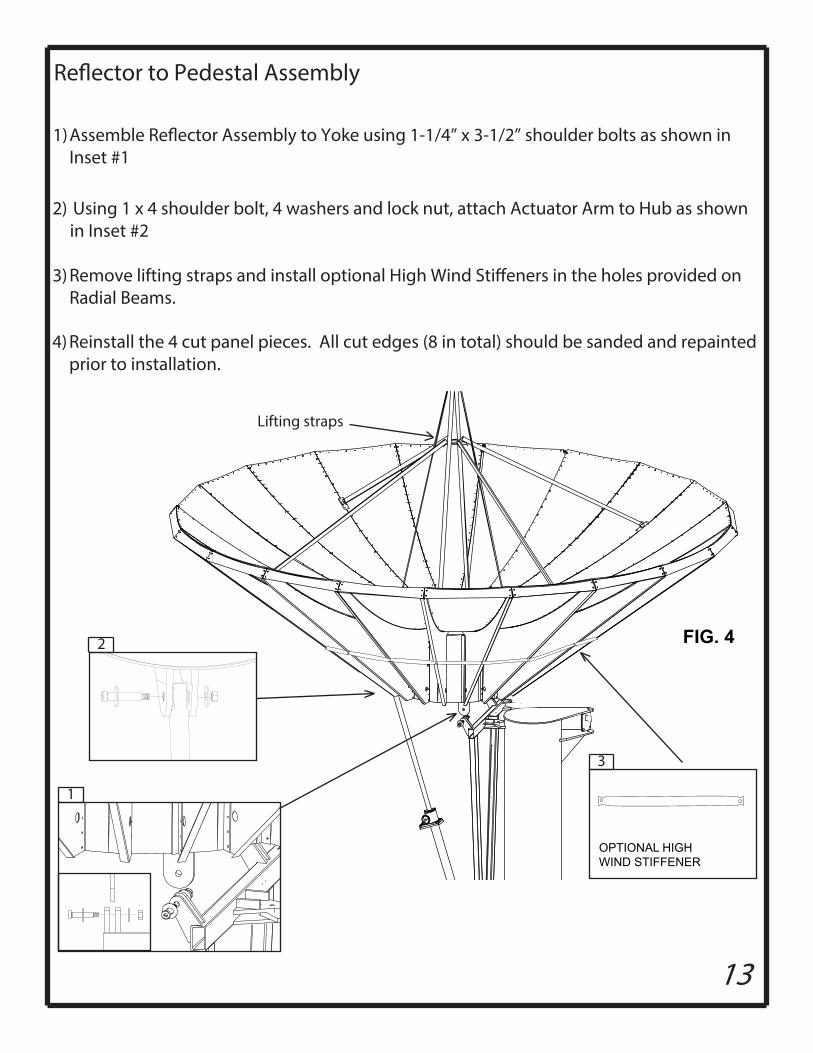
13
Lifting straps
2) Using 1 x 4 shoulder bolt, 4 washers and lock nut, attach Actuator Arm to Hub as shownin Inset #2
3)
1
2
1)Inset #1
FIG. 4
3
OPTIONAL HIGHWIND STIFFENER
Remove lifting straps and install optional High Wind Sti�eners in the holes provided onRadial Beams.
4) Reinstall the 4 cut panel pieces. All cut edges (8 in total) should be sanded and repainted prior to installation.
14
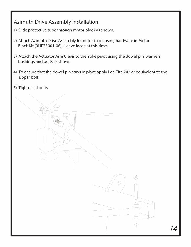
Azimuth Drive Assembly Installation1) Slide protective tube through motor block as shown.
2) Attach Azimuth Drive Assembly to motor block using hardware in Motor Block Kit (3HP75001-06). Leave loose at this time.
3) Attach the Actuator Arm Clevis to the Yoke pivot using the dowel pin, washers, bushings and bolts as shown.
4) To ensure that the dowel pin stays in place apply Loc-Tite 242 or equivalent to the upper bolt.
5) Tighten all bolts.
15
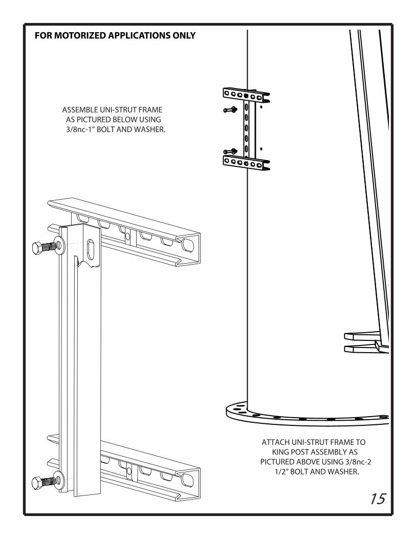
ASSEMBLE UNI-STRUT FRAME AS PICTURED BELOW USING 3/8nc-1” BOLT AND WASHER.
ATTACH UNI-STRUT FRAME TO KING POST ASSEMBLY AS
PICTURED ABOVE USING 3/8nc-2 1/2” BOLT AND WASHER.
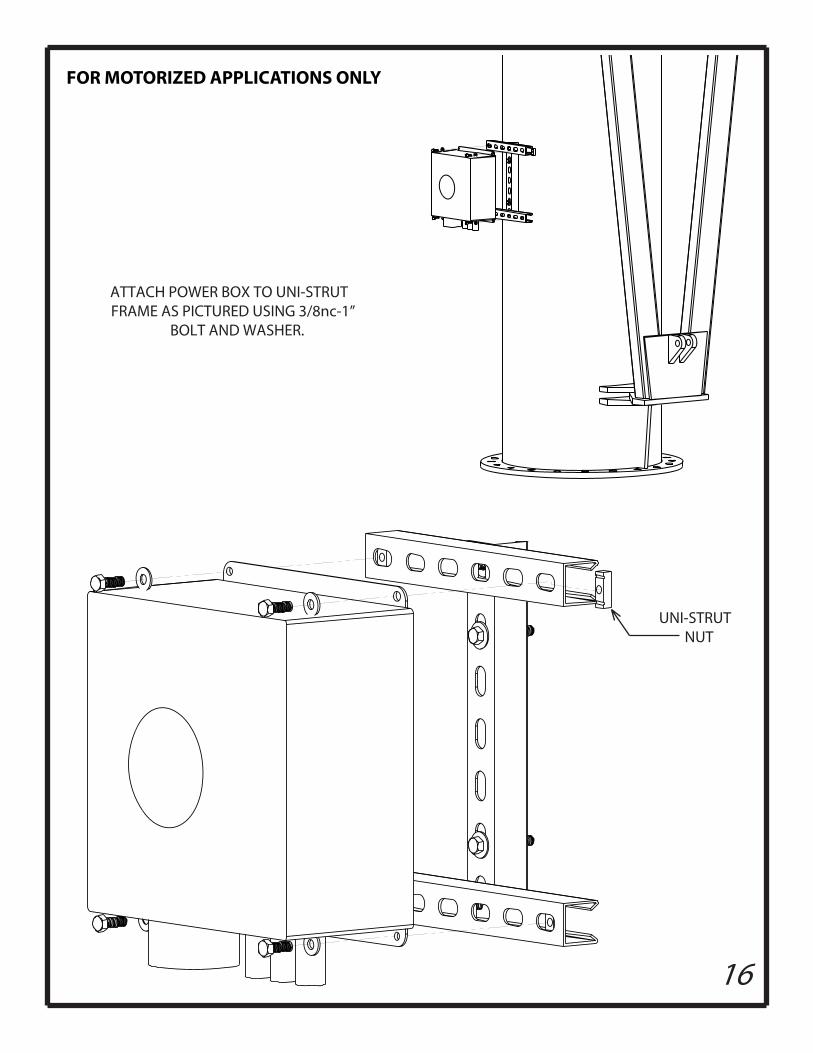
FOR MOTORIZED APPLICATIONS ONLY
16
UNI-STRUT NUT
ATTACH POWER BOX TO UNI-STRUT FRAME AS PICTURED USING 3/8nc-1”
BOLT AND WASHER.
FOR MOTORIZED APPLICATIONS ONLY
17
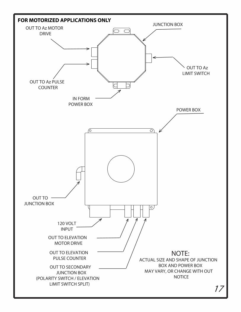
POWER BOX
OUT TO SECONDARY JUNCTION BOX
(POLARITY SWITCH / ELEVATION LIMIT SWITCH SPLIT)
OUT TO ELEVATION MOTOR DRIVE
OUT TO ELEVATIONPULSE COUNTER
120 VOLT INPUT
OUT TO JUNCTION BOX
NOTE:ACTUAL SIZE AND SHAPE OF JUNCTION
BOX AND POWER BOX MAY VARY, OR CHANGE WITH OUT
NOTICE
JUNCTION BOX
OUT TO Az PULSE COUNTER
OUT TO Az MOTORDRIVE
OUT TO AzLIMIT SWITCH
IN FORM POWER BOX
FOR MOTORIZED APPLICATIONS ONLY
18
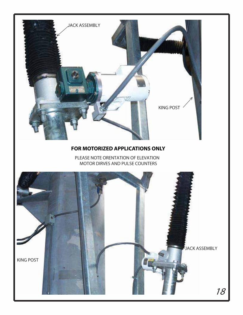
JACK ASSEMBLY
KING POST
PLEASE NOTE ORENTATION OF ELEVATION MOTOR DIRVES AND PULSE COUNTERS
JACK ASSEMBLY
KING POST
FOR MOTORIZED APPLICATIONS ONLY
19
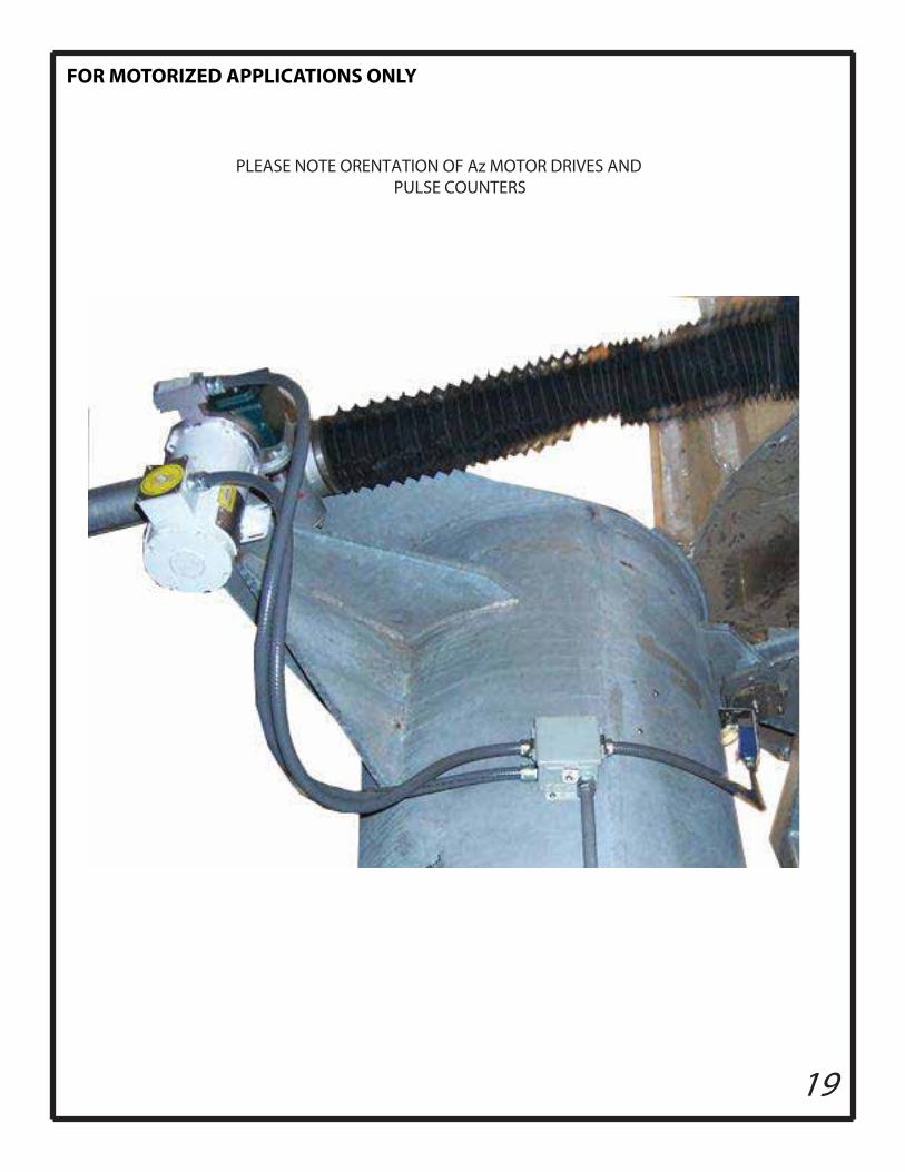
PLEASE NOTE ORENTATION OF Az MOTOR DRIVES AND PULSE COUNTERS
FOR MOTORIZED APPLICATIONS ONLY
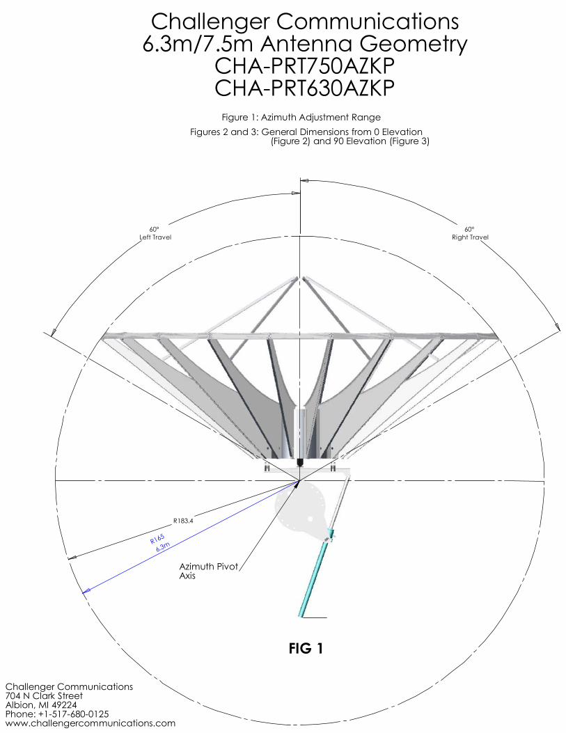
60°Left Travel
60°Right Travel
R183.4
R165
6.3m
Azimuth PivotAxis
Challenger Communications6.3m/7.5m Antenna Geometry
CHA-PRT750AZKPCHA-PRT630AZKP
FIG 1
Figure 1: Azimuth Adjustment RangeFigures 2 and 3: General Dimensions from 0 Elevation (Figure 2) and 90 Elevation (Figure 3)
Challenger Communications704 N Clark StreetAlbion, MI 49224Phone: +1-517-680-0125www.challengercommunications.com
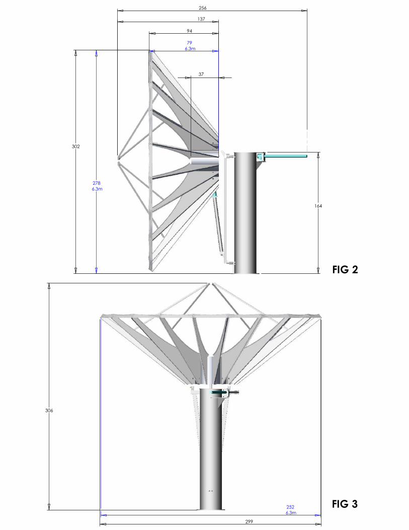
302
164
137
37
94
2786.3m
796.3m
256
FIG 2
306
299
2526.3m
FIG 3


