Assessing and Improving Interoperability of Distributed Systems Dissertation zur Erlangung des mathematisch-naturwissenschaftlichen Doktorgrades “Doctor rerum naturalium” der Georg-August-Universität Göttingen im Promotionsprogramm Computer Science (PCS) der Georg-August University School of Science (GAUSS) vorgelegt von Thomas Rings aus Gotha Göttingen, 2012
Transcript
Assessing and Improving Interoperability ofDistributed Systems
Dissertationzur Erlangung des mathematisch-naturwissenschaftlichen Doktorgrades
“Doctor rerum naturalium”der Georg-August-Universität Göttingen
im Promotionsprogramm Computer Science (PCS)der Georg-August University School of Science (GAUSS)
vorgelegt von
Thomas Ringsaus Gotha
Göttingen, 2012
Betreuungsausschuss
Prof. Dr. Jens Grabowski,Institut für Informatik, Georg-August-Universität Göttingen
Prof. Dr. Stephan Waack,Institut für Informatik, Georg-August-Universität Göttingen
Prof. Dr. Dieter Hogrefe,Institut für Informatik, Georg-August-Universität Göttingen
Prof. Dr. Helmut Neukirchen,Faculty of Industrial Engineering, Mechanical Engineering and Computer Science,University of Iceland
Mitglieder der Prüfungskommission
Referent: Prof. Dr. Jens Grabowski,Institut für Informatik, Georg-August Universität Göttingen
Korreferent: Prof. Dr. Arnulf Quadt,II. Physikalisches Institut, Georg-August Universität Göttingen
Korreferent: Prof. Dr. César Viho,Education and Research Department in Computer Science andElectrical Engineering, ISTIC-University of Rennes 1
Weitere Mitglieder der Prüfungskommission
Prof. Dr. Dieter Hogrefe,Institut für Informatik, Georg-August-Universität Göttingen
Prof. Dr. Ulrich Sax,Geschäftsbereich Informationstechnologie, Universitätsmedizin Göttingen
Prof. Dr. Ramin Yahyapour,Gesellschaft für wissenschaftliche Datenverarbeitung Göttingen mbH (GWDG),Institut für Informatik, Georg-August-Universität Göttingen
Tag der mündlichen Prüfung: 23. Januar 2013
Abstract
Achieving interoperability of distributed systems offers means for the development of newand innovative business solutions. Interoperability allows the combination of existing ser-vices provided on different systems, into new or extended services. Such an integrationcan also increase the reliability of the provided service. However, achieving and assessinginteroperability is a technical challenge that requires high effort regarding time and costs.The reasons are manifold and include differing implementations of standards as well as theprovision of proprietary interfaces. The implementations need to be engineered to be inter-operable. Techniques that assess and improve interoperability systematically are required.
For the assurance of reliable interoperation between systems, interoperability needs tobe assessed and improved in a systematic manner. To this aim, we present the Interoper-ability Assessment and Improvement (IAI) process, which describes in three phases howinteroperability of distributed homogeneous and heterogeneous systems can be improvedand assessed systematically. The interoperability assessment is achieved by means of in-teroperability testing, which is typically performed manually. For the automation of inter-operability test execution, we present a new methodology including a generic developmentprocess for a complete and automated interoperability test system. This methodology pro-vides means for a formalized and systematic assessment of systems’ interoperability in anautomated manner. Compared to manual interoperability testing, the application of ourmethodology has the following benefits: wider test coverage, consistent test execution, andtest repeatability.
We evaluate the IAI process and the methodology for automated interoperability test-ing in three case studies. Within the first case study, we instantiate the IAI process andthe methodology for Internet Protocol Multimedia Subsystem (IMS) networks, which werepreviously assessed for interoperability only in a manual manner. Within the second andthird case study, we apply the IAI process to assess and improve the interoperability of gridand cloud computing systems. Their interoperability assessment and improvement is chal-lenging, since cloud and grid systems are, in contrast to IMS networks, heterogeneous. Wedevelop integration and interoperability solutions for grids and Infrastructure as a Service(IaaS) clouds as well as for grids and Platform as a Service (PaaS) clouds. These solutionsare unique and foster complementary usage of grids and clouds, simplified migration ofgrid applications into the cloud, as well as efficient resource utilization. In addition, weassess the interoperability of the grid-cloud interoperability solutions. While the tests forgrid-IaaS clouds are performed manually, we applied our methodology for automated inter-operability testing for the assessment of interoperability to grid-PaaS cloud interoperabilitysuccessfully. These interoperability assessments are unique in the grid-cloud communityand provide a basis for the development of standardized interfaces improving the interoper-ability between grids and clouds.
Zusammenfassung
Interoperabilität von verteilten Systemen ist eine Grundlage für die Entwicklung von neuenund innovativen Geschäftslösungen. Sie erlaubt es existierende Dienste, die auf verschiede-nen Systemen angeboten werden, so miteinander zu verknüpfen, dass neue oder erweiterteDienste zur Verfügung gestellt werden können. Außerdem kann durch diese Integration dieZuverlässigkeit von Diensten erhöht werden. Das Erreichen und Bewerten von Interoper-abilität stellt jedoch eine finanzielle und zeitliche Herausforderung dar. Zur Sicherstellungund Bewertung von Interoperabilität werden systematische Methoden benötigt.
Um systematisch Interoperabilität von Systemen erreichen und bewerten zu können,wurde im Rahmen der vorliegenden Arbeit ein Prozess zur Verbesserung und Beurteilungvon Interoperabilität (IAI) entwickelt. Der IAI-Prozess beinhaltet drei Phasen und kann dieInteroperabilität von verteilten, homogenen und auch heterogenen Systemen bewerten undverbessern. Die Bewertung erfolgt dabei durch Interoperabilitätstests, die manuell oder au-tomatisiert ausgeführt werden können. Für die Automatisierung von Interoperabilitätstestswird eine neue Methodik vorgestellt, die einen Entwicklungsprozess für automatisierte In-teroperabilitätstestsysteme beinhaltet. Die vorgestellte Methodik erleichtert die formale undsystematische Bewertung der Interoperabilität von verteilten Systemen. Im Vergleich zurmanuellen Prüfung von Interoperabilität gewährleistet die hier vorgestellte Methodik einehöhere Testabdeckung, eine konsistente Testdurchführung und wiederholbare Interoperabil-itätstests.
Die praktische Anwendbarkeit des IAI-Prozesses und der Methodik für automatisierteInteroperabilitätstests wird durch drei Fallstudien belegt. In der ersten Fallstudie wer-den Prozess und Methodik für Internet Protocol Multimedia Subsystem (IMS) Netzw-erke instanziiert. Die Interoperabilität von IMS-Netzwerken wurde bisher nur manuellgetestet. In der zweiten und dritten Fallstudie wird der IAI-Prozess zur Beurteilung undVerbesserung der Interoperabilität von Grid- und Cloud-Systemen angewendet. Die Be-wertung und Verbesserung dieser Interoperabilität ist eine Herausforderung, da Grid- undCloud-Systeme im Gegensatz zu IMS-Netzwerken heterogen sind. Im Rahmen der Fallstu-dien werden Möglichkeiten für Integrations- und Interoperabilitätslösungen von Grid- undInfrastructure as a Service (IaaS) Cloud-Systemen sowie von Grid- und Platform as a Ser-vice (PaaS) Cloud-Systemen aufgezeigt. Die vorgestellten Lösungen sind in der Literaturbisher nicht dokumentiert worden. Sie ermöglichen die komplementäre Nutzung von Grid-und Cloud-Systemen, eine vereinfachte Migration von Grid-Anwendungen in ein Cloud-System sowie eine effiziente Ressourcennutzung. Die Interoperabilitätslösungen werdenmit Hilfe des IAI-Prozesses bewertet. Die Durchführung der Tests für Grid-IaaS-Cloud-Systeme erfolgte manuell. Die Interoperabilität von Grid-PaaS-Cloud-Systemen wird mitHilfe der Methodik für automatisierte Interoperabilitätstests bewertet. Interoperabilitätstestsund deren Beurteilung wurden bisher in der Grid- und Cloud-Community nicht diskutiert,obwohl sie eine Basis für die Entwicklung von standardisierten Schnittstellen zum Erre-ichen von Interoperabilität zwischen Grid- und Cloud-Systemen bieten.
Acknowledgements
At this point, I thank all the people that supported me in writing this thesis. First of all, Iwould like to thank my doctoral supervisor Prof. Dr. Jens Grabowski, who made it possiblefor me to conduct research in a stimulating environment and under excellent conditions.Not only his friendly guidance over the last years as well as his financial support for lots oftrips were the basis for the successful completion of this thesis.
Also, I am very grateful to Prof. Dr. Arnulf Quadt and Prof. Dr. César Viho for agreeingto act as a referee for this thesis. I would also like to thank the remaining members of mydefense committee: Prof. Dr. Dieter Hogrefe, Prof. Dr. Ulrich Sax, and Prof. Dr. RaminYahyapour.
Moreover, I want to thank all my current and prior colleagues at the Institute of ComputerScience and at the European Telecommunications Standards Institute (STF331, STF370)for an enjoyable and scientifically inspiring environment, as well as various after-work ac-tivities. Sharing individual problems as well as discussing novel solutions have made myday-to-day work balanced and varied. I am especially grateful for the effort that SteffenHerbold, Patrick Harms, Michael Cohrs, and Philip Makedonski put into the proof readingof this thesis. I also thank all diploma students and student workers that assisted me in tryingseveral directions and approaches helping me to save time with their implementations.
Especially, I would like to thank Benjamin Zeiss, Stephan Schulz, and Tibor Kálmán forthe interesting scientific discussions, cooperation and for their constant encouragement.
Special thanks go to my parents Barbara and Hartmut for their education and supportduring my schooldays and studies. They have always encouraged me and my sister to dothe best in all matters of life.
I thank especially my wife Fernanda for her understanding for my work and her enduringpatience for months of traveling. Without her unconditional love and her bringing up of ourlittle son Adrian, this thesis would never have been finished.
Last but not least, I want to thank my family and all my friends for their support.
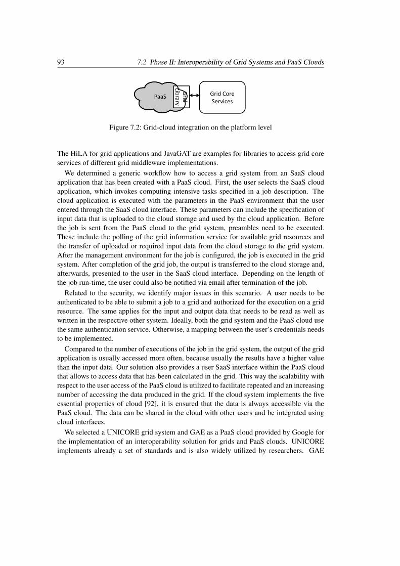
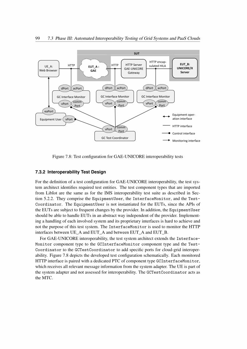
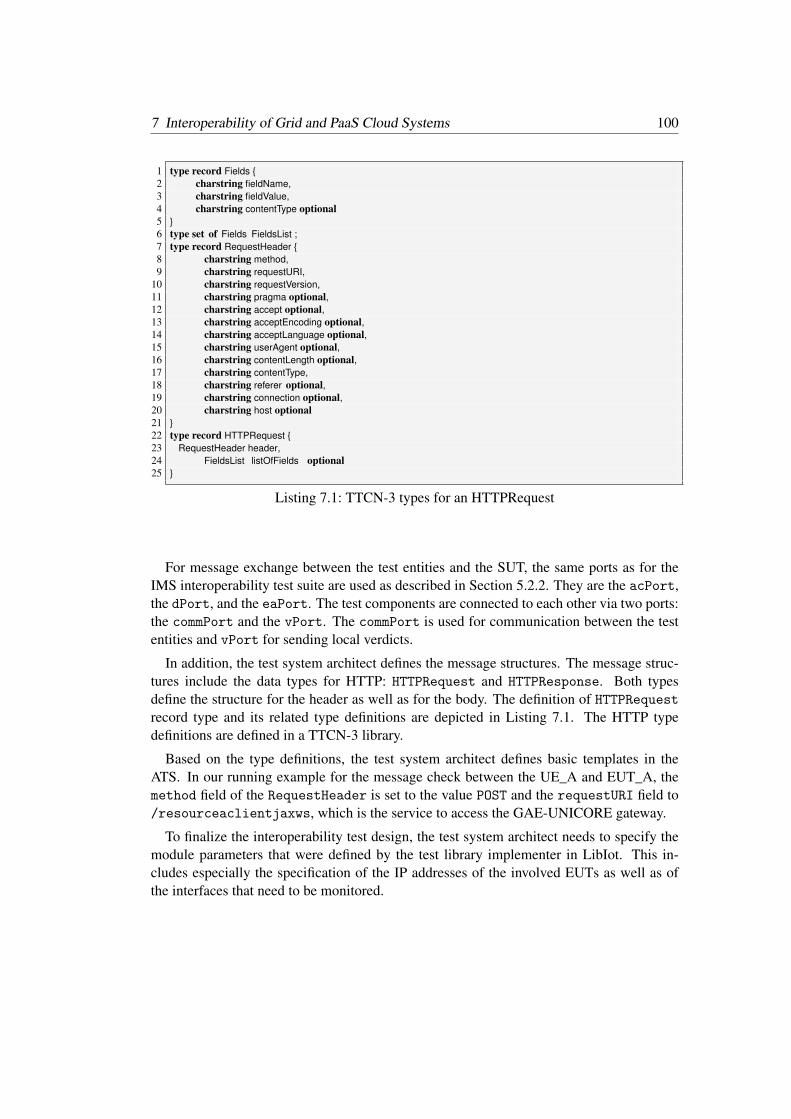
7 Interoperability of Grid and PaaS Cloud Systems 917.1 Phase I: Comparison of Grid Systems and PaaS Clouds . . . . . . . . . . . 917.2 Phase II: Interoperability of Grid Systems and PaaS Clouds . . . . . . . . . 927.3 Phase III: Automated Interoperability Testing of Grid Systems and PaaS
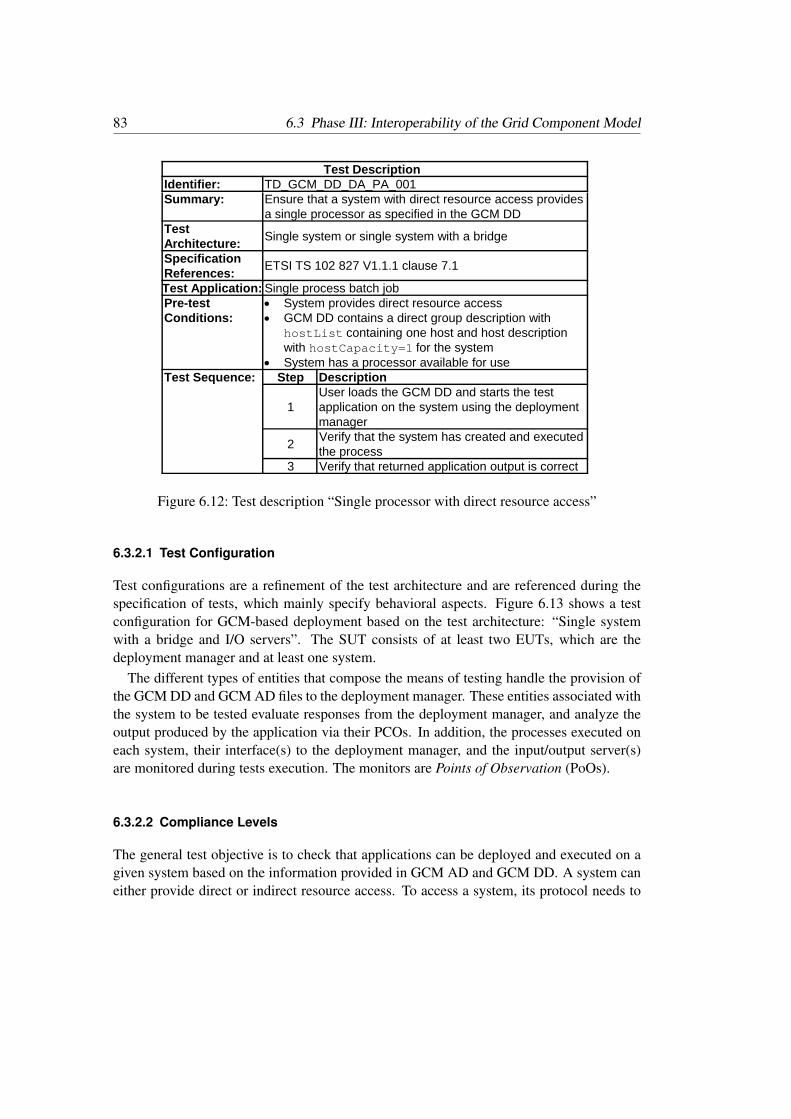
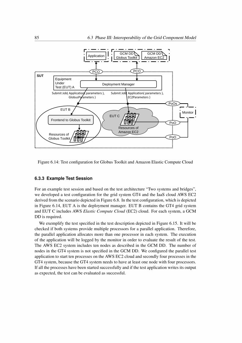
Interoperability of distributed systems is vital to succeed in today’s market. On one hand,interoperability can be leveraged to open new markets, to foster innovation, and to enablemass markets by creating new and innovative solutions through the composition of inter-operable systems. This allows service enrichment by integrating services only available inanother system and to increase productivity by consuming such extended services. Further-more, interoperability provides means to increase system availability and reliability. On theother hand, customers demand interoperable and diverse systems as well as competition ina market, which are both fostered by interoperability. An example for interoperability is thepossibility to use a cell phone in different networks implemented by different vendors. Forthis scenario, the different networks are required to be interoperable.
The development of new solutions by combining purchased or in-house systems improvesthe quality of the resulting system and allows a faster development of new solutions lead-ing to a shorter time to market [69]. A system A that is developed by vendor X should beable to interoperate with a system B, which provides the same or complementary function-ality as system A but is implemented by vendor Y. Both systems need to be engineered tobe interoperable. An interim approach is an interoperability gateway solution that allowscommunication between systems. An interoperability gateway converts messages receivedby one system into a representation understandable by another system to allow their inter-operation. The long-term approach to achieve interoperable systems is the implementationof a common set of open standards1. Standards define architectures and interfaces as wellas specify protocols to be used for communication via these interfaces. Ideal standardsare independent of implementations and leave space for innovation. Even if standards areassumed unambiguous, which is rarely the case, testing is needed to validate that imple-mentations conform to standards. A further step is to test whether implementations areable to interoperate, because the implementation of the same standard does not necessarilymean that systems are able to interoperate. One of the reasons is that standards are oftenspecified ambiguously [144] and can, therefore, be interpreted differently by developers orvendors. Furthermore, options within a standard might lead to inconsistencies. Therefore,the standards themselves need to be assessed and engineered for interoperability, as well.
1Throughout the whole thesis we use “standard”, which can be exchanged with “specification” dependingon the progress of the standardization. We consider such a standard to be standardized and publishedby an organization such as Open Grid Forum (OGF), World Wide Web Consortium (W3C), or EuropeanTelecommunications Standards Institute (ETSI).
1 Introduction 2
Interoperability testing assesses the end-to-end service provision between systems pro-vided by different vendors. Ideally, all participating systems are tested and assessed forinteroperability against one reference implementation, which is a fully functional imple-mentation of one or more standards. Today’s interoperability testing is still largely per-formed in a time consuming and resource intensive manual manner [14]. This is causedby the high number of systems and standards that are involved in complex distributed sys-tems. The implementations, their interfaces as well as standards need to be engineered tobe interoperable. In addition, interoperation needs to be reliable and, therefore, assessed forcorrect functioning. The interoperability engineering and assessment has many constraintsregarding interoperability solutions and interoperable systems. Therefore, measures for in-teroperability engineering and assessment can only be developed and applied by experts ofthe systems. Techniques for a systematic assessment and improvement of interoperabilityare required. In addition, interoperability testing is not transitive [146]: If a system A inter-operates with a system B and system B interoperates with a system C, it does not necessarilymean that system A interoperates with system C. This also results in a large amount of re-quired test executions, which grows exponentially with the number of systems involved.Furthermore, after a new version of one of the systems is released, all interoperability testsneed to be re-executed against all other participating systems to assess their interoperability.
In this thesis, we present a process to systemically assess and improve interoperabilityof distributed homogeneous and heterogeneous systems in a systematic manner to copewith the issues described above. We develop a new methodology for automated assessmentof interoperability that enables a systematic specification of an automated interoperabilitytest system. We show the practical application of the process and the methodology forhomogeneous systems, i.e., for interoperability of IP Multimedia Subsystem (IMS) networksand for heterogeneous systems, i.e., for interoperability of grid and cloud systems.
1.1 Contribution of the Thesis
This thesis advances the state-of-the-art regarding improving and assessing interoperabilityof distributed systems with the following contributions.
• The Interoperability Assessment and Improvement (IAI) process (Chapter 3) de-scribes how systems are analyzed, improved, and assessed for interoperability in threephases. The analyses are based on documents that specify the functionalities of thesystems as well as on interoperability initiatives. The improvement is either based onstandards or on interoperability gateways. The assessment is done by means of inter-operability tests. The IAI process is applicable for homogeneous and heterogeneousdistributed systems. Homogeneous systems are systems that implement the samestandards. Heterogeneous systems do not implement the same standards, but provideeither common or complementary functionality as the basis for the interoperation ofthe systems.
3 1.2 Impact
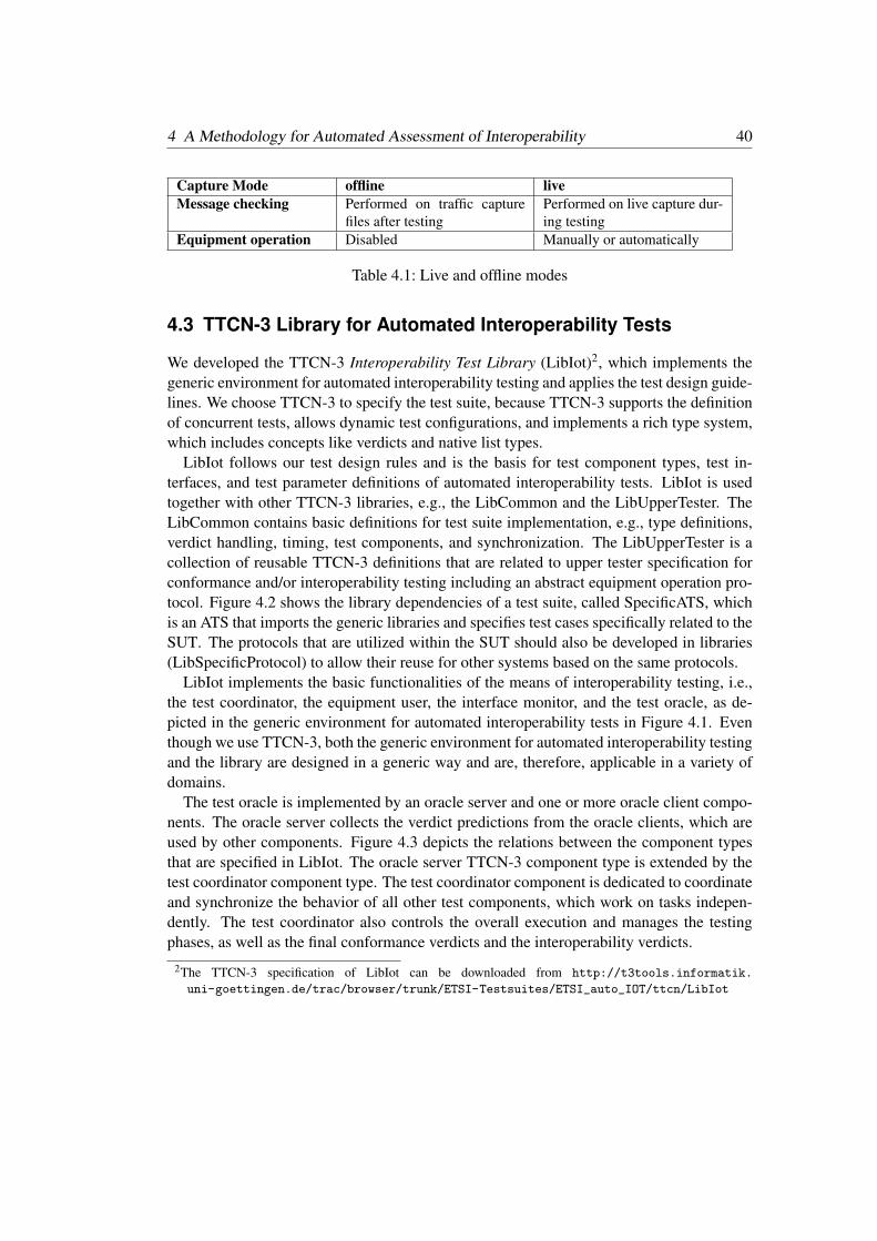
• A methodology for automated interoperability testing (Chapter 4) that is com-prised of four main parts. 1) We specify a generic environment for interoperabilitytests with message checks, which builds the basis for a development of automatedinteroperability tests. 2) We provide guidelines for interoperability test design andtest automation. 3) We describe a generic library for automated interoperability testsusing TTCN-3 that implements the generic environment as well as the guidelines.4) We develop a generic development process for the systematic specification of acomplete and structured automated interoperability test system.This methodology provides a first step towards a formalized and systematic assess-ment of interoperability in an automated manner and can be utilized in the IAI pro-cess.
We evaluate the two contributions in case studies. From the results of the case studies, wepresent three further contributions to the state-of-the-art of interoperability testing of IMSnetworks as well as of interoperable grid and clouds computing systems:
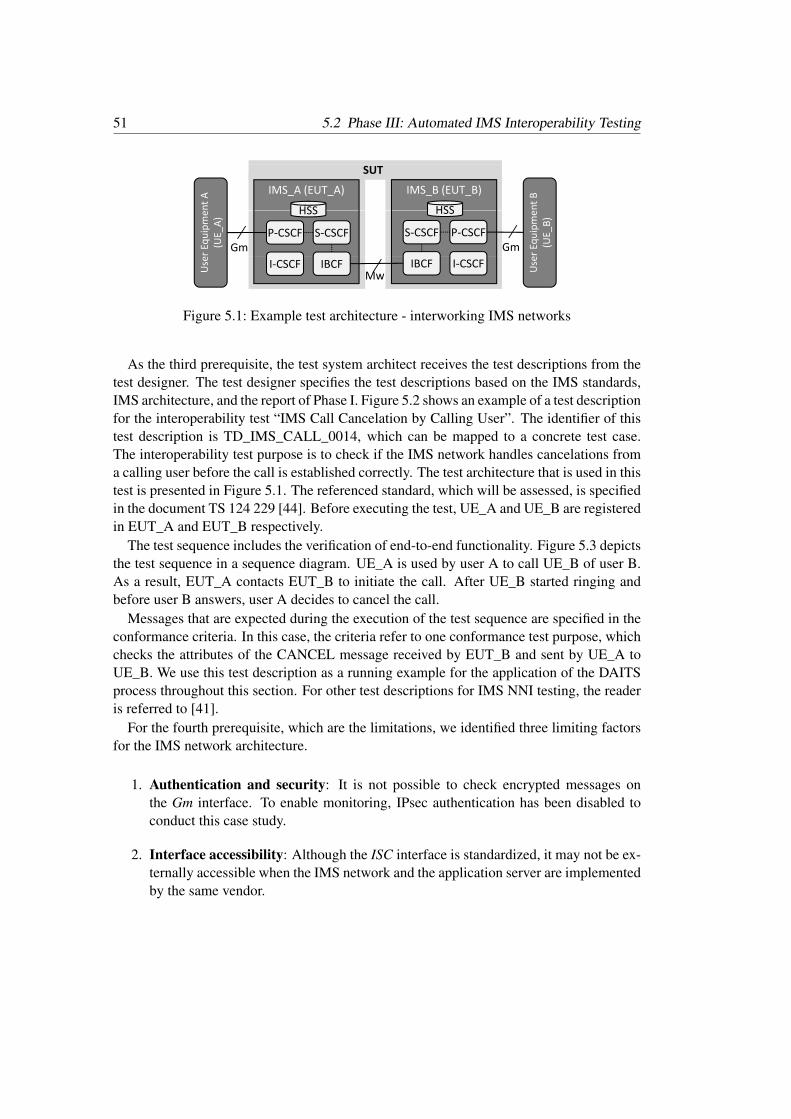
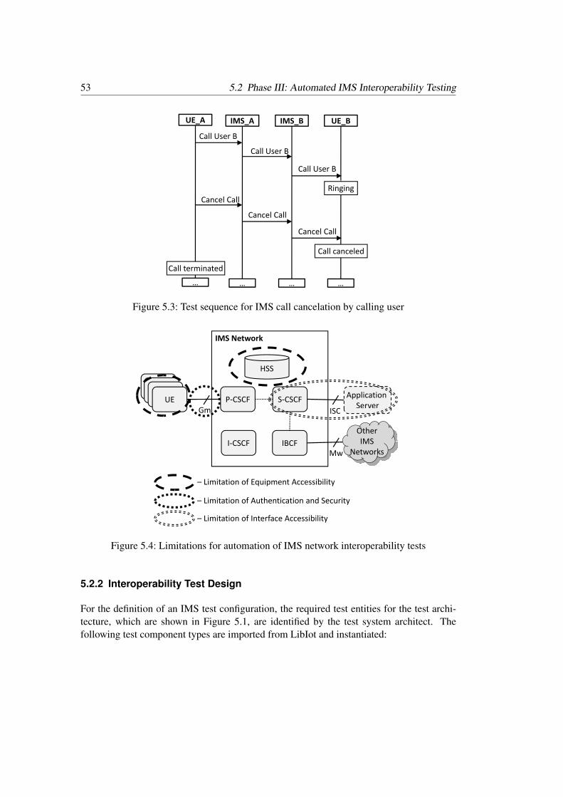
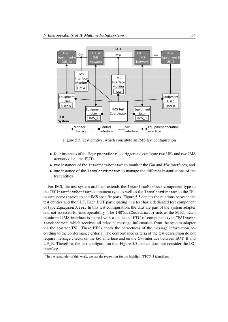
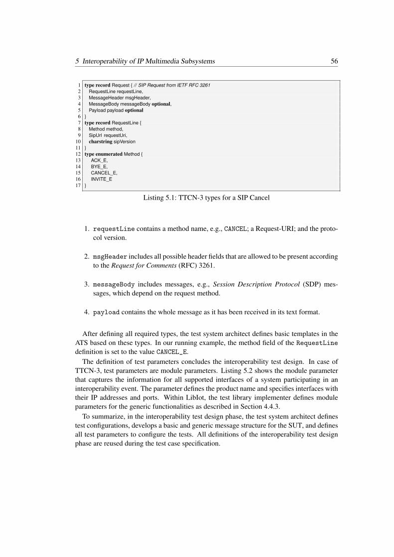
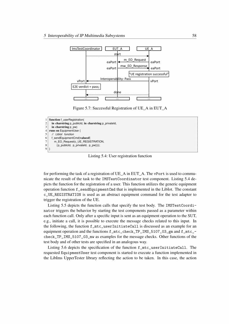
• Automated execution of interoperability tests for IMS networks with an interoper-ability test suite for IMS implemented using TTCN-3 and developed by instantiatingthe methodology for automated interoperability testing (Section 5.1). The automatedinteroperability test execution avoids the previously performed manual execution andimproves the efficiency if IMS interoperability testing.
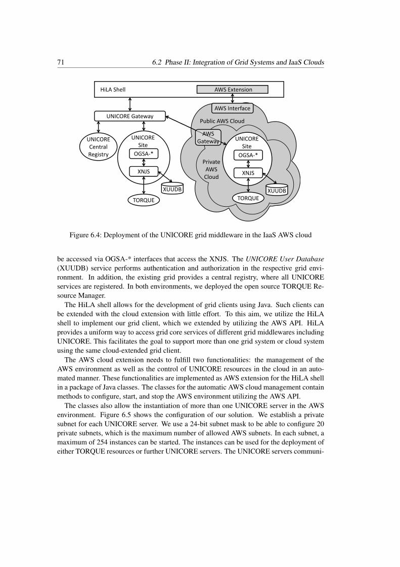
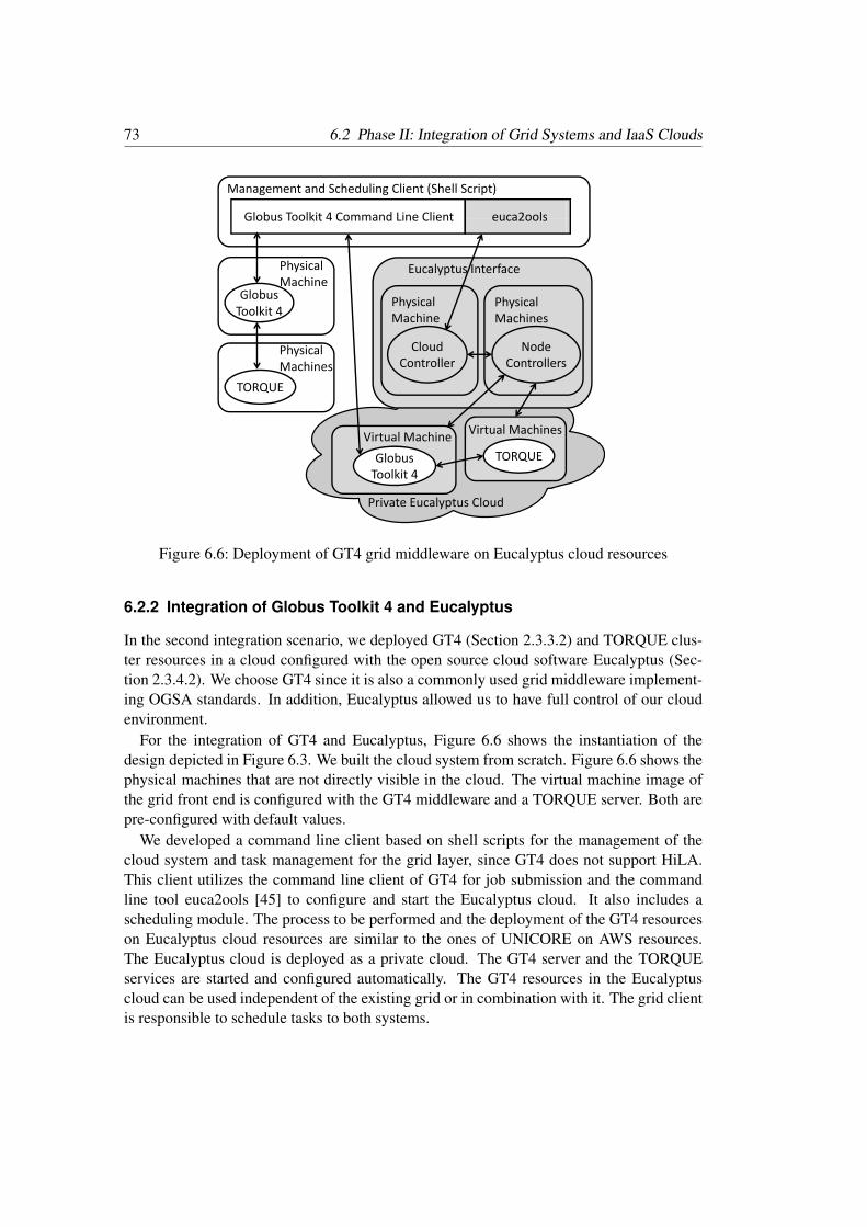
• Two feasibility studies of the integration of grid computing systems and clouds,which show that grid systems and clouds are able to interoperate on different lev-els, i.e., between grid systems and Infrastructure as a Service (IaaS) clouds (Sec-tion 6.2) as well as between grid systems and Platform as a Service (PaaS) clouds(Section 7.2). We present unique solutions to achieve their interoperability.
• The assessment of the interoperability of grid computing systems and cloudsby application of interoperability tests for interoperable grids and IaaS clouds (Sec-tion 6.3) as well as for grids and PaaS clouds (Section 7.3). Both are unique in thegrid-cloud community and have neither been developed nor executed, yet. The resultsof the assessment can be used as a basis for grid and cloud standardization.
1.2 Impact
The results of this dissertation have been peer-reviewed and published in three internationaljournals and three international conference proceedings. The subsequent list presents thejournal articles:
• Springer International Journal on Software Tools for Technology Transfer (STTT,accepted, to appear in 2013): A Generic Interoperability Testing Framework and aSystematic Development Process for Automated Interoperability Testing. ThomasRings, Patrick Poglitsch, Stephan Schulz, Luca Serazio, and Theofanis Vassiliou-Gioles.
1 Introduction 4
• IARIA International Journal On Advances in Systems and Measurements (Vol.3(1&2) 2011): A Testing Framework for Assessing Grid and Cloud InfrastructureInteroperability. Thomas Rings, Jens Grabowski, and Stephan Schulz.
• Springer Journal of Grid Computing: Special Issue on Grid Interoperability (JoGCVol. 7(3) 2009): Grid and Cloud Computing: Opportunities for Integration withthe Next Generation Network. Thomas Rings, Geoff Caryer, Julian Gallop, JensGrabowski, Tatiana Kovacikova, Stephan Schulz, and Ian Stokes-Rees.
In the following, we list the conference publications:
• IEEE 5th International Conference on Cloud Computing (CLOUD 2012): PragmaticIntegration of Cloud and Grid Computing Infrastructures. Thomas Rings and JensGrabowski.
• IARIA 2nd International Conference on Advances in System Testing and Valida-tion Lifecycle (VALID 2010): On the Standardization of a Testing Framework forApplication Deployment on Grid and Cloud Infrastructures. Thomas Rings, JensGrabowski, and Stephan Schulz.
• 13th International Conference on Intelligence in Next Generation Networks (ICIN2009): Grid/Cloud Computing Interoperability, Standardization and the Next Gen-eration Network. Geoff Caryer, Julian Gallop, Jens Grabowski, Tatiana Kovacikova,Thomas Rings, Stephan Schulz, Ian Stokes-Rees.
Furthermore, the author identified the topics for and supervised one Master thesis, oneBachelor thesis, and one student project with relation to the overall topic of this thesis:
• Maik Doleys: Using Cloud Computing Resources in Grid Systems: An Integration ofAmazon Web Services into UNICORE 6. Bachelor Thesis. 2011.
• Dalia Dahman: Extension of a Globus Toolkit 4 Grid System by a Virtual RuntimeEnvironment based on Eucalyptus. Master Thesis. 2010.
• Dalia Dahman: Establishment and Configuration of a Grid Environment Based onGlobus Toolkit 4 (GT4) Using Torque Portable Batch System (PBS) and the Deploy-ment of a Grid Application. Student Project. 2010.
1.3 Structure of the Thesis
This thesis is structured as follows. In Chapter 2, we introduce the prerequisites that areneeded across all chapters. We describe concepts related to interoperability and softwaretesting as well as to the systems under study. In Chapter 3, we present the IAI processthat is applied for assessing and improving interoperability of systems. The IAI processcomprises activities for analyzing interoperability, engineering interoperability, and inter-operability testing. In Chapter 4, we present a methodology for automated interoperability
5 1.3 Structure of the Thesis
testing that can be applied in the third phase of the IAI process. In Chapter 5, we applythe IAI process and the methodology for automated interoperability testing for the IMS. InChapter 6, we apply the IAI process for grid systems and IaaS clouds with manual interop-erability assessment due to their diverse interfaces. In Chapter 7, we assess and improve theinteroperability of grid and PaaS cloud systems by the application of the IAI process. Weconclude this thesis with a summary, a discussion, and an outlook in Chapter 8.
2 Prerequisites
This chapter describes the prerequisites that are the basis for this entire work. In Sec-tion 2.1, we define interoperability and discuss the different categories and levels of in-teroperability. In Section 2.2, we describe the main concepts of software testing includ-ing types of testing, a test specification development process, as well as Testing and TestControl Notation Version 3 (TTCN-3). Afterwards, in Section 2.3, we focus on the sys-tems that we analyze and apply in our case studies. They include mainly cloud and gridsystems, as well as the telecommunication service IMS. This chapter is partly adaptedfrom [117, 118, 119, 120, 121, 122].
2.1 Interoperability
Interoperability is the “ability of two or more systems or components to exchange informa-tion and to use the information that has been exchanged” [71]. The information is exchangedacross possibly standardized interfaces using communication protocols and procedures toprovide end-to-end functionalities to end users of the systems. These functionalities arespecified by standards and implemented within components of different systems, whichneed to be assessed for interoperability with other systems. A system is “a collection ofcomponents organized to accomplish a specific function or set of functions” [71].
Closely related but distinct to interoperability is portability. Portability is “the ease withwhich a system or component can be transferred from one hardware or software environ-ment to another” [71]. A software is portable in case the software does not rely on featuresthat are unique to a particular type of computer or software environment. For example, aportable software can be installed on a Linux as well as on a Microsoft Windows operatingsystem. However, this does not inherently mean that the operating systems are interopera-ble.
Interoperability is crucial to ensure delivery of services across systems from differentvendors. It can be distinguished into four levels, which are from the bottom to the top: tech-nical, syntactical, semantical, and organizational interoperability [144]. The upper levelsrely on the lower levels, such as that semantical interoperability cannot take place withoutsyntactical interoperability.
Technical interoperability means to enable machine-to-machine communication based onhardware or software systems. It focuses mainly on communication protocols and the in-frastructure that is required for their operation. Syntactical interoperability considers the
2 Prerequisites 8
System X‘ System X System Y
Service X‘1
System X
Service X1
System X
Service Y1
System Y
1b 1c
Service X‘2 Service X2 Service Y2
1a
2 2 2
1a – Interoperability within a systemp y y1b – Interoperability between the same form of systems1c – Interoperability between different forms of systems
Figure 2.1: Types of interoperability
data formats that are used in communication protocols. This means that a well defined syn-tax and encoding is required for messages that are transferred by communication protocols.Semantical interoperability is related to the meaning of content. If semantical interoper-ability is fulfilled, humans understand the same when interpreting the same content. It isnot centered on machine interpretation. Organizational interoperability is the ability of ameaningful communication of data over different infrastructures between different orga-nizations. Organizational interoperability includes the linking of business processes [85].The objects for interoperability differ in each level: signals in technical interoperability, datain syntactical interoperability, information in semantical interoperability, and processes inorganization interoperability [85]. In this thesis, we discuss technical and syntactical inter-operability, which we both call “interoperability” in the remainder of this work. We do notconsider semantical or organizational interoperability [144].
Depending on the kind of distributed systems, interoperability can be interpreted differ-ently. In general, we distinguish between three different types of technical interoperability:interoperability within a system, between the same form of systems, and between differentforms of systems [34]. Figure 2.1 depicts these different types.
Interoperability within a system is the ability of services provided by a single systemto communicate by well defined interfaces (Figure 2.1–1a). This means that the serviceswithin a specific system are able to interoperate through common, standardized, or other-wise agreed upon interfaces inside the infrastructure. A practical example is the requirementto utilize two different components such as a billing and a monitoring service implementedby different vendors that need to communicate within one system. This type is also calledintegration, which is “the process of combining software components, hardware compo-nents, or both into an overall system” [71].
Interoperability between systems is usually located at user domain level, i.e., interoper-ability between end users. Figure 2.1–1b shows the interoperation between two systems of
9 2.2 Software Testing
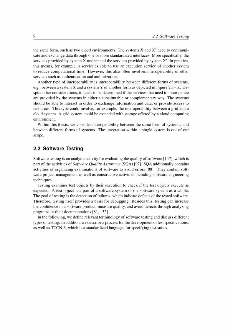
the same form, such as two cloud environments. The systems X and X’ need to communi-cate and exchange data through one or more standardized interfaces. More specifically, theservices provided by system X understand the services provided by system X’. In practice,this means, for example, a service is able to use an execution service of another systemto reduce computational time. However, this also often involves interoperability of otherservices such as authentication and authorization.
Another type of interoperability is interoperability between different forms of systems,e.g., between a system X and a system Y of another form as depicted in Figure 2.1–1c. De-spite other considerations, it needs to be determined if the services that need to interoperateare provided by the systems in either a substitutable or complementary way. The systemsshould be able to interact in order to exchange information and data, or provide access toresources. This type could involve, for example, the interoperability between a grid and acloud system. A grid system could be extended with storage offered by a cloud computingenvironment.
Within this thesis, we consider interoperability between the same form of systems, andbetween different forms of systems. The integration within a single system is out of ourscope.
2.2 Software Testing
Software testing is an analytic activity for evaluating the quality of software [147], which ispart of the activities of Software Quality Assurance (SQA) [97]. SQA additionally containsactivities of organizing examinations of software to avoid errors [88]. They contain soft-ware project management as well as constructive activities including software engineeringtechniques.
Testing examines test objects by their execution to check if the test objects execute asexpected. A test object is a part of a software system or the software system as a whole.The goal of testing is the detection of failures, which indicate defects of the tested software.Therefore, testing itself provides a basis for debugging. Besides this, testing can increasethe confidence in a software product, measure quality, and avoid defects through analyzingprograms or their documentations [81, 132].
In the following, we define relevant terminology of software testing and discuss differenttypes of testing. In addition, we describe a process for the development of test specifications,as well as TTCN-3, which is a standardized language for specifying test suites.
2 Prerequisites 10
2.2.1 Definition of Required Test Terminologies
The following terms and definitions are used throughout this thesis.
• Test: A test means “an activity in which a system or component is executed underspecified conditions, the results are observed or recorded, and an evaluation is madeof some aspect of the system or component.” [71].
• Implementation Under Test (IUT): An IUT is “an implementation of one or moreOpen Systems Interconnection (OSI) protocols in an adjacent user/provider relation-ship, being that part of a real open system which is to be studied by testing” [73].
• Equipment Under Test (EUT): An EUT corresponds to a complete system that canconsist of several soft- and hardware components. An EUT will be tested for inter-operability against other EUTs. This definition updates the original definition for thisterm provided in [36].
• System Under Test (SUT): An SUT is “the real open system in which the IUT” [73]or respectively the EUTs “reside” [73]. The collection of all EUTs is called theSUT [36].
• Requirement: A requirement is “(1) A condition or capability needed by a user tosolve a problem or achieve an objective. (2) A condition or capability that mustbe met or possessed by a system or system component to satisfy a contract, standard,specification, or other formally imposed documents. (3) A documented representationof a condition or capability as in (1) or (2)” [71]. Related to testing, this means thata requirement describes a specific behavior of the IUT or respectively EUT, i.e., aseries of stimuli to and expected outputs from the IUT or respectively EUT that canbe assessed by means of a test [118].
• Implementation Conformance Statement (ICS): A protocol ICS is “a statementmade by the supplier of an OSI implementation or system, stating which capabili-ties have been implemented for a given OSI protocol” [73]. An ICS is basically a“checklist for providing information about an implementation to a specification, bypresenting in a uniform manner the implemented capabilities (e.g., functions, fea-tures) and options as well as limitations of the implementation” [152].
• Test Architecture: A test architecture is an “abstract description of logical entitiesas well as their interfaces and communication links involved in a test” [35] related tothe SUT.
• Test Configuration: A test configuration is a “concrete instance of a test architecturedefined on the basis of test components, ports and their connection” [35] related tothe whole test system.
• Test Purpose: A test purpose is “a prose description of a narrowly defined objectiveof testing, focusing on a single conformance requirement as specified in the appropri-ate OSI International Standard or CCITT Recommendation (e.g. verifying the support
11 2.2 Software Testing
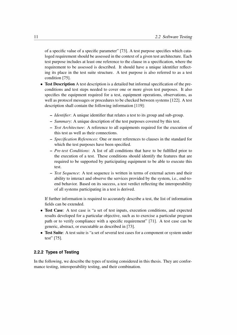
of a specific value of a specific parameter” [73]. A test purpose specifies which cata-loged requirement should be assessed in the context of a given test architecture. Eachtest purpose includes at least one reference to the clause in a specification, where therequirement to be assessed is described. It should have a unique identifier reflect-ing its place in the test suite structure. A test purpose is also referred to as a testcondition [75].
• Test Description A test description is a detailed but informal specification of the pre-conditions and test steps needed to cover one or more given test purposes. It alsospecifies the equipment required for a test, equipment operations, observations, aswell as protocol messages or procedures to be checked between systems [122]. A testdescription shall contain the following information [119]:
– Identifier: A unique identifier that relates a test to its group and sub-group.– Summary: A unique description of the test purposes covered by this test.– Test Architecture: A reference to all equipments required for the execution of
this test as well as their connections.– Specification References: One or more references to clauses in the standard for
which the test purposes have been specified.– Pre-test Conditions: A list of all conditions that have to be fulfilled prior to
the execution of a test. These conditions should identify the features that arerequired to be supported by participating equipment to be able to execute thistest.
– Test Sequence: A test sequence is written in terms of external actors and theirability to interact and observe the services provided by the system, i.e., end-to-end behavior. Based on its success, a test verdict reflecting the interoperabilityof all systems participating in a test is derived.
If further information is required to accurately describe a test, the list of informationfields can be extended.
• Test Case: A test case is “a set of test inputs, execution conditions, and expectedresults developed for a particular objective, such as to exercise a particular programpath or to verify compliance with a specific requirement” [71]. A test case can begeneric, abstract, or executable as described in [73].
• Test Suite: A test suite is “a set of several test cases for a component or system undertest” [75].
2.2.2 Types of Testing
In the following, we describe the types of testing considered in this thesis. They are confor-mance testing, interoperability testing, and their combination.
2 Prerequisites 12
SUT
Conformance Testing
IUTUser
Conformance Testing
Figure 2.2: Conformance testing
2.2.2.1 Conformance Testing
Conformance testing is “testing the extent to which an Implementation Under Test (IUT)satisfies both static and dynamic conformance requirements” [36]. This means that confor-mance testing is generally used to check whether an implementation follows the require-ments stated in a standard.
In conformance testing, one IUT is tested with functional black-box tests to check if theIUT is conform to a standard. Figure 2.2 schematically depicts this test setup. The IUTis embedded in the SUT, which is a testing environment that also includes parts that arerequired by the IUT to provide its service or functionality to the user. Conformance testingusually requires the development and implementation of sophisticated testing tools, e.g.,based on TTCN-3 [32]. Such tools support the simulation of the environment, which isneeded for a proper execution of the IUT.
2.2.2.2 Interoperability Testing
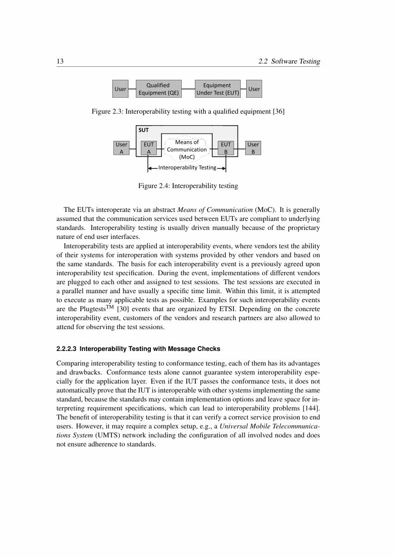
Interoperability is assessed through interoperability testing, which is the “activity of provingthat end-to-end functionality between (at least) two communicating systems is as requiredby the base standard(s) on which those systems are based” [36]. In interoperability test-ing, all participating systems are usually tested and assessed for interoperability against aqualified equipment [36], which is illustrated in Figure 2.3. A Qualified Equipment (QE)is a reference implementation, which is a fully functional implementation of one or morestandards. But the determination of a reference implementation for interoperability testingis difficult; because it needs to be assured that the reference implementation implementsthe standards correctly. However, each participating system implementation should be ableto interoperate with all the others, not only with the reference implementation. Systemsshould rather be tested for interoperability against each other. Therefore, we updated thedefinition of interoperability testing described in [36]. We removed the QE and, therefore,avoid its determination. Each tested system in interoperability testing is called an EUT.The collection of all EUTs is called the SUT [36]. Figure 2.4 depicts the interoperabilitytest setup. Using this approach, interoperability testing provides a feasible way to assess iftwo or more systems are able to communicate or interoperate, i.e., to understand exchangeddata.
13 2.2 Software Testing
User Equipment Under Test (EUT)
Qualified Equipment (QE) User
Figure 2.3: Interoperability testing with a qualified equipment [36]
SUT
UserA
UserB
EUTA
EUTB
Means ofCommunication
(MoC)
Interoperability Testing
Figure 2.4: Interoperability testing
The EUTs interoperate via an abstract Means of Communication (MoC). It is generallyassumed that the communication services used between EUTs are compliant to underlyingstandards. Interoperability testing is usually driven manually because of the proprietarynature of end user interfaces.
Interoperability tests are applied at interoperability events, where vendors test the abilityof their systems for interoperation with systems provided by other vendors and based onthe same standards. The basis for each interoperability event is a previously agreed uponinteroperability test specification. During the event, implementations of different vendorsare plugged to each other and assigned to test sessions. The test sessions are executed ina parallel manner and have usually a specific time limit. Within this limit, it is attemptedto execute as many applicable tests as possible. Examples for such interoperability eventsare the PlugtestsTM [30] events that are organized by ETSI. Depending on the concreteinteroperability event, customers of the vendors and research partners are also allowed toattend for observing the test sessions.
2.2.2.3 Interoperability Testing with Message Checks
Comparing interoperability testing to conformance testing, each of them has its advantagesand drawbacks. Conformance tests alone cannot guarantee system interoperability espe-cially for the application layer. Even if the IUT passes the conformance tests, it does notautomatically prove that the IUT is interoperable with other systems implementing the samestandard, because the standards may contain implementation options and leave space for in-terpreting requirement specifications, which can lead to interoperability problems [144].The benefit of interoperability testing is that it can verify a correct service provision to endusers. However, it may require a complex setup, e.g., a Universal Mobile Telecommunica-tions System (UMTS) network including the configuration of all involved nodes and doesnot ensure adherence to standards.
2 Prerequisites 14
SUTEUTA
UserA
UserB
EUTB
End‐to‐end functionality
Message checks
Figure 2.5: Interoperability testing with two EUTs and message checks
In our approach, we use interoperability testing in combination with conformance testingso that it is possible to check the conformance to a standard related to the interoperationand, in addition, to check if the EUTs are interoperable [119, 122]. This approach extendsinteroperability testing with the monitoring of the communication among the EUTs andupdates the approach described by [36] by removing the QE as well as defining the SUT. Inthe remainder of this thesis, we call this combination of testing interoperability testing withmessage checks. This means that during the execution of interoperability tests, messages arerecorded within test execution traces at (possibly standardized) interfaces between differentEUTs by monitors to analyze the compliance of the recorded messages to the standards.This allows the verification of the correctness of protocol procedures, while the assessmentof interoperability takes place. Message checks also provide a basis for fault analysis. Incontrast to traditional conformance testing, message checks assess requirements that areonly related to the interoperation. An interoperability test setup combining interoperabilitytests with message checks is depicted in Figure 2.5. The end-to-end functionality is assessedfrom the end user points of view while the message checks take place at the intermediateinterfaces. Although this approach is not a replacement for conformance testing, it offersan economic alternative to gain insights about the conformance of equipment participatingin an interoperability test to a standard.
Interoperability tests with message checks are also described in the literature using differ-ent terminologies. The main idea of combining conformance testing with interoperabilitytesting has been presented, e.g., by [140, 146, 148]. Viho et al. [146] provide a formalframework for interoperability testing. They present a general architecture of interoper-ability based on lower and upper testers as defined by the international ISO/IEC multipartstandard 9646 OSI Conformance Testing Methodology and Framework (CTMF) [74]. TheCTMF standards define the upper tester and the lower tester strongly related with the OSImodel. Interoperability testing with message checks can be used independent of the OSImodel.
If interoperability tests with message checks are applied in interoperability events, thevalidation of standards can be performed in addition to the assessment of interoperability.The results of the tests including interoperability issues as well as discrepancy of the appliedstandards are reported to the responsible technical committee. This feedback is then usedto improve the standards.
15 2.2 Software Testing
Base StandardBase Standard
Test Specification Development ProcessIdentification and Cataloging of
Test Purposes Definition and Test Suite Structure Description3.
Test Description Specification4.
Test Case Development5 Test Case Development5.
Validation of Test Cases6.
Final conformance or interoperability test specificationinteroperability test specification
Figure 2.6: Test specification development process
2.2.3 Test Specification Development Process
Based on the test specification development process for Internet Protocol (IP) testing estab-lished by ETSI [31], we developed the generic test specification development process [118],which is depicted in Figure 2.6. The steps of the process build a bridge over the large gap inthe levels of abstraction between a base standard and a final conformance or interoperabilitytest specification.
In Step 1, requirements are identified from relevant base specifications. Requirementsmay be published in a requirements catalog. Then, in Step 2, the ICS is specified. Thisstep is essentially a high level check list of features and capabilities supported by the IUT.The ICS can be used to quickly identify if two implementations of the same standard havethe potential to interoperate. In Step 3, test purposes are specified for the identified require-ments and a logical grouping of the test purposes, the Test Suite Structure (TSS) is defined.If a requirement can be assessed using a given form of testing then a test purpose specifiesverdict criteria for a test. After that, in Step 4, for each test purpose an informal test descrip-tion is developed. In Step 5, either test purpose-based or test description-based test casesare specified.
The final Step 6 includes the validation of the test cases and is normally not done by thetest developers. The validation ensures that the test cases are specified correctly. It may
2 Prerequisites 16
be done by executing the test cases at an interoperability event or by running test cases bymeans of conformance test tools against a number of different implementations of a givenstandard. Problems detected during the validation should be reported to the test developersand can lead to changes in the test case specifications. The validated test cases form thefinal interoperability or conformance test specification.
2.2.4 Testing and Test Control Notation Version 3 (TTCN-3)
TTCN-3 [43] is an internationally standardized language, which is specifically designed forthe specification of tests. It is developed and maintained by the ETSI Technical Committeefor Methods for Testing and Specification (TC MTS), a team of leading testing experts fromindustry and research. TTCN-3 has been in use in standardization effort as well as in theindustry for over 10 years. TTCN-3 can be applied to a variety of application domainsand types of testing. It has been proven to work in very large and complex industrial tests,e.g., for 3rd Generation Mobile Telecommunications (3G) network elements. There areTTCN-3 test suites for, e.g., IMS, Long Term Evolution (LTE), and the Session InitiationProtocol (SIP). TTCN-3 can be used not only for specifying and implementing functionaltests, but also for scalability, robustness, and stress tests. In this work, we apply TTCN-3for interoperability testing.
The TTCN-3 language is similar to typical general purpose programming languages’textual syntax. Most concepts of general purpose programming languages can be foundin TTCN-3 as well, e.g. data types, variables, functions, parameters, loops, conditionalstatements, and import mechanisms. In addition, test related concepts ease the specificationof test suites.
TTCN-3 supports distributed testing through the notion of test components: Parallel TestComponents (PTCs) can be created dynamically in addition to the Main Test Component(MTC). Each test component runs concurrently and may, therefore, execute test behaviorin parallel to other test components. For the communication between test components andbetween test components and the SUT, operations such as send and receive can be used totransfer messages via ports. The values of these messages are specified using templates.TTCN-3 templates may involve wildcards and provide a powerful matching mechanism tovalidate expected test data.
Further concepts that ease the specification of tests are: test verdict handling, logging,timeout timers, and defaults. The first three concepts are self-explanatory. Defaults aretypically used for specifying alternative behavior that deals with unexpected events. Sincea receive operation blocks until it observes a message that matches the specified template,defaults can be activated to catch, e.g. the expiration of a timer or any unexpected message.
To allow the automated execution of TTCN-3 test suites, TTCN-3 tools can be used tocompile TTCN-3 test specifications into executable tests. However, TTCN-3 test specifica-tions use abstract communication mechanisms. Thus, to make TTCN-3 test specificationsexecutable, an adaptation layer is required. Figure 2.7 depicts the TTCN-3 test system archi-
17 2.3 Systems Under Study
Test System User
Test Control (TC) Test Logging (TL)ne
nting
ec
TCI
( ) f ( )
TTCN‐3 Abstract Test Suite (ATS)
Compo
nHa
ndl
Cod
TRISystem Adapter (SA) Platform Adapter (PA)
System Under Test (SUT)
Figure 2.7: TTCN-3 test system architecture
tecture. Test cases are specified in TTCN-3 within an Abstract Test Suite (ATS). A SystemAdapter (SA) entity that implements operations of the TTCN-3 Runtime Interface (TRI) [32]and a Coding/Decoding (CD) entity that implements operations of the TTCN-3 Control In-terface (TCI) [32, 126] must also be realized. For those ports that are mapped to Points ofControl and Observation (PCOs), the SA realizes send and receive operations by using thecommunication mechanisms of the SUT, e.g., sockets. The CD is responsible for the trans-lation between the abstract TTCN-3 values and the concrete bit-level data encoding used bythe SUT.
Using TTCN-3 has the following advantages in comparison to proprietary test languagesor low-level test implementations. The high abstraction level speeds up test development.The re-usability is higher, because both the abstract TTCN-3 test specifications and theadapters can be re-used independent of each other. Furthermore, due to the fact that TTCN-3is standardized and various TTCN-3 tools are available, a vendor lock-in is avoided. Forfurther introduction to TTCN-3, the reader is referred to [149].
2.3 Systems Under Study
The systems that we studied for interoperability in the case studies are distributed systems.A distributed system is “a collection of independent computers that appears to its users asa single coherent system” [137]. In this section, we describe the systems that we analyzedand applied in the case studies: Web services, compute clusters, grid computing systems,cloud computing systems, and IMS.
2.3.1 Web Services
Most grid and cloud systems commonly leverage Web service technology. According tothe World Wide Web Consortium (W3C), a Web service is “a software system designed tosupport interoperable machine-to-machine interaction over a network. It has an interface de-
2 Prerequisites 18
scribed in a machine-processable format (specifically WSDL). Other systems interact withthe Web service in a manner prescribed by its description using SOAP messages, typicallyconveyed using HTTP with an XML serialization in conjunction with other Web-relatedstandards” [153]. In the following, we describe five basic Web service standards relevantfor this work:
1. eXtensible Markup Language (XML) [150] is a markup language, that defines a setof rules for encoding documents in a common format to which messages comply thatfacilitates data sharing across different interfaces of Web services.
2. SOAP [151] is a protocol specification that defines XML grammar to allow com-munication of Web services independent of their utilized platform. SOAP forms thefoundation of the Web service protocol stack. SOAP messages are usually transmittedover Hypertext Transfer Protocol (HTTP).
3. HTTP “is an application-level protocol for distributed, collaborative, hypermediainformation systems” [52].
4. Web Services Description Language (WSDL) [17] is an XML dialect used for thespecification of the functionality that is offered by a Web service using XML. WithWSDL, methods of a service are described in an abstract and programming languageindependent way to allow platform independent access.
5. Universal Description, Discovery and Integration (UDDI) [110] is used to specify anXML-based registry that is utilized for finding Web services. It allows organizationsto publish information about their Web services, which can be found and bound byother Web services.
A Web service by itself is stateless, i.e., the Web service cannot remember information,or persist its state, from one invocation to another. The Web Services Resource Frame-work (WSRF) [7] is a specification that provides means to keep the state of a Web service.However, the state is not integrated into the Web service. A separate entity, which is calledresource, stores the state information. Each resource has a unique key for its identifica-tion and can keep multiple values of, e.g., complex data types. The Web service togetherwith its belonging resource is called a Web Service Resource (WS-Resource). The EndpointReference (EPR) is the address of a WS-Resource [130].
2.3.2 Cluster Computing Systems
Compute clusters are tightly interconnected but operationally independent computers, onwhich user accessible software runs to manage and control concurrent computing tasks thatinstantiate a common application program [134]. The independent computers are called
19 2.3 Systems Under Study
Submission
SchedulingResource and
SubmittingClients
gResource andQueue
Management
Queue A
Queue X Queuing Scheduler
Executing
…
WorkerNode 1
… WorkerNode n
Output
Figure 2.8: Cluster architecture
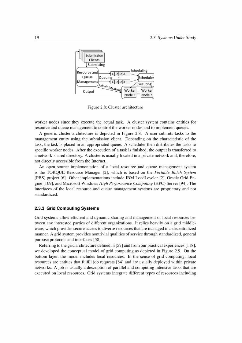
worker nodes since they execute the actual task. A cluster system contains entities forresource and queue management to control the worker nodes and to implement queues.
A generic cluster architecture is depicted in Figure 2.8. A user submits tasks to themanagement entity using the submission client. Depending on the characteristic of thetask, the task is placed in an appropriated queue. A scheduler then distributes the tasks tospecific worker nodes. After the execution of a task is finished, the output is transferred toa network-shared directory. A cluster is usually located in a private network and, therefore,not directly accessible from the Internet.
An open source implementation of a local resource and queue management systemis the TORQUE Resource Manager [2], which is based on the Portable Batch System(PBS) project [6]. Other implementations include IBM LoadLeveler [2], Oracle Grid En-gine [109], and Microsoft Windows High Performance Computing (HPC) Server [94]. Theinterfaces of the local resource and queue management systems are proprietary and notstandardized.
2.3.3 Grid Computing Systems
Grid systems allow efficient and dynamic sharing and management of local resources be-tween any interested parties of different organizations. It relies heavily on a grid middle-ware, which provides secure access to diverse resources that are managed in a decentralizedmanner. A grid system provides nontrivial qualities of service through standardized, generalpurpose protocols and interfaces [58].
Referring to the grid architecture defined in [57] and from our practical experiences [118],we developed the conceptual model of grid computing as depicted in Figure 2.9. On thebottom layer, the model includes local resources. In the sense of grid computing, localresources are entities that fulfill job requests [84] and are usually deployed within privatenetworks. A job is usually a description of parallel and computing intensive tasks that areexecuted on local resources. Grid systems integrate different types of resources including
2 Prerequisites 20
Grid Portal Grid Application
Grid Core Services
Grid Scheduler
Resource Management
Information Management
Data Management
Execution Management
Security
Local Resources StorageComputing Sensors Services
Figure 2.9: Layered conceptual model of grid computing
computing, storage, sensors, and services. These resources usually deploy a predefinedsoftware stack. For example, on compute clusters, which belong to the computing resourcetype, user accessible software runs to control computing tasks as described in Section 2.3.2.Similarly, the other resource types deploy an already pre-configured infrastructure that isusable within private networks by utilization of their specific protocols and interfaces. Theprotocols are then utilized by the grid core services offered by a grid middleware to accessthe local resources from a public network and of other organizations. The grid core servicesinclude services for the management of information, data, execution, and resources.
The grid core services are utilized by grid schedulers that schedule jobs over severalgrid infrastructures. In addition, these services are directly usable via grid portals or gridapplications. Grid middleware systems deploy security services that provide authenticationand authorization functionalities for the entire grid core services.
2.3.3.1 Open Grid Service Architecture (OGSA)
The Open Grid Services Architecture (OGSA) [56], which is maintained by the Open GridForum (OGF) [104], is a Service Oriented Architecture (SOA) that defines and standardizesthe grid core services for the implementation of a basic grid computing system in an ab-stract manner [56]. OGSA leverages existing Web service specifications and makes themsuitable for the grid environment by adding grid specific characteristics. These grid en-hanced Web services are called grid services [91]. The grid core services are largely in-dependent of each other and do not need to be present in an OGSA system. OGSA aimsto enable interoperability between heterogeneous and distributed grid systems as well asreduce the administration complexity [56]. OGSA can be extended by other standards thatspecify specific areas of the grid core services. The extensions include OGSA-Basic Execu-tion Service (OGSA-BES) [54], OGSA-Resource Usage Service (OGSA-RUS) [101], andOGSA-Data Access and Integration (OGSA-DAI) [24].
21 2.3 Systems Under Study
2.3.3.2 Globus Toolkit 4
Globus Toolkit 4 (GT4) [59] is a grid middleware that provides all required components forthe deployment of a grid computing system. It is maintained by the Globus Alliance [63]as a community-based and open-source set of services and software libraries. The toolkitincludes components for security, information infrastructure, resource management, exe-cution management, data management, communication, fault detection, and portability. Itis packaged as a set of components that can be used either independently or together todevelop grid applications [55].
GT4 defines protocols as well as APIs for each component. In addition, it provides open-source reference implementations in C and Java for client-side APIs. A wide variety ofhigher-level services, tools and applications have been developed based on GT4. Severalof these services and tools are integrated in the components of GT4, while others are dis-tributed through other sources [59]. GT4 implements the WSRF and meets the requirementsof the OGSA, which both foster interoperability [64].
2.3.3.3 UNICORE 6
Uniform Interface to Computing Resources (UNICORE) 6 is a grid middleware that pro-vides access to distributed computing and storage systems [82]. It is maintained by theJülich Supercomputing Centre [53].
UNICORE implements a three-layered architecture: the client layer, the service layer,and the system layer [136]. The client layer on the top of the architecture includes threedifferent kinds of clients [83] that can be utilized to access UNICORE resources: the UNI-CORE command line client; the UNICORE rich client, a graphical user interface based onthe Eclipse Rich Client Platform [23]; and the open source High Level Application Pro-gramming Interface (HiLA) shell that allows development of grid clients using Java.
The core of the architecture is the service layer. It comprises all services and componentsthat are required for accessing a UNICORE grid. They include an authentication service,an information service, a central registry, and a workflow engine. UNICORE’s internalexecution management engine (XNJS) maps the abstract job description to concrete jobdescriptions for a specific resource, e.g., a compute cluster.
The system layer on the bottom of the architecture includes the Test System Interface(TSI) component, which provides the access to the actual resource management or computecluster system. This means that the TSI translates abstracted commands (from the upperlayer) into system specific commands (to the lower layer) [136].
Regarding interoperability, UNICORE supports a variety of standards. UNICORE im-plements the full Web service stack based on WSRF and allows to access the XNJS viastandardized OGSA interfaces for job management. In addition, UNICORE supports theGrid Laboratory for a Uniform Environment (GLUE) 2.0 information model and OGSA-ByteIO for data transfer [136].
2 Prerequisites 22
2.3.3.4 Grid Component Model (GCM)
The provision of common interfaces for the allocation of resources for application deploy-ment in different computing and storage systems is a crucial requirement, because userswish to access multiple resources of several systems simultaneously and in a cost savingway. An approach towards such an interface is described in the ETSI Grid ComponentModel (GCM) standards. The main objective of GCM is the creation of a uniform interfacefor allocating resources for applications, where resources may be provided across differentgrid systems. The GCM is an interoperability gateway approach with a standardized andabstract communication protocol based on XML descriptors, i.e., the GCM Deployment De-scriptor (DD) [33] and the GCM Application Descriptor (AD) [40]. GCM DD and GCMAD provide formal specifications of resource information for the involved and possiblyheterogeneous systems [34].
2.3.4 Cloud Computing Systems
Cloud computing “is a model for enabling ubiquitous, convenient, on-demand network ac-cess to a shared pool of configurable computing resources (e.g., networks, servers, storage,applications, and services) that can be rapidly provisioned and released with minimal man-agement effort or service provider interaction” [92]. Cloud computing systems fulfill fiveessential properties [92]:
• On-demand self-service: Consumers can instantiate computing, storage, and net-work capabilities in an automated manner according to their demand;
• Broad network access: The capabilities can be used and accessed by common inter-faces over the network by any kind of client platform;
• Resource pooling: Physical resources are pooled dynamically into virtual resources,which are utilized in a multi-tenant manner having a sense of data location indepen-dence without having control or knowledge about the exact data location;
• Rapid elasticity: Resources can be allocated and released rapidly (in the orders ofminutes) according to the demand;
• Measured service: Cloud systems utilize a metering capability to control and opti-mize resources automatically [92].
Cloud systems are classified in a layered service model containing the following layersfrom bottom to top as depicted in Figure 2.10: Infrastructure as a Service (IaaS), PaaS, andSoftware as a Service (SaaS) [92]. Within the illustrated clouds on each level, the figuredepicts the interfaces to the services that are provisioned by each layer, respectively. IaaSclouds include virtualized resources, e.g., storage, processors, and networks. Within thevirtualized resources, network architects are able to deploy and run arbitrary software viaresource management interfaces. Network architects check the status of the IaaS clouds
23 2.3 Systems Under Study
nSaaS
ApplicatioWeb‐based Application
General Applications Business Services
Mobile AppsEnd User
D l d
tform
PaaS
Runtime EnvironmentControl InterfaceDeveloper
Developed on
PlatResource
ManagementFault
ToleranceDynamic
ProvisioningLoad
Balancing
Deployed on
astructure
IaaS
System Monitoring Interface
Resource Manage‐ment Interface
Architect
Infra
Virtualization NetworkComputing Storage I/O
Figure 2.10: Service model of cloud computing
via system monitoring interfaces. On the PaaS level, services for automated resource man-agement, fault tolerance, dynamic provisioning, and load balancing are deployed. Thesefunctionalities are utilized within the runtime environment in a transparent manner via acontrol interface, e.g., an Application Programming Interface (API) that is used by an ap-plication developer. The developer only has control over the deployed applications, but notover the resources. The SaaS layer provides Web interfaces for end users to access ap-plications without requiring local software installations. The users are only able to applyapplication specific configurations, but cannot control the cloud infrastructure. Each layerdeploys security mechanisms to protect the resources and services they offer.
A cloud system is deployed in one of the following models: private, public, hybrid, andcommunity [79, 92]. Public clouds offer services for public use and are physically locatedon the premises of the cloud provider. Public clouds serve multiple customers using a multi-tenant model. Private clouds can be hosted on the premises of a single organization but alsooff the premises managed by a cloud provider. The access to a private cloud is dedicatedand restricted to a single customer. A hybrid cloud is the mixed employment of privateand public clouds, e.g., to maintain control over sensitive data, which is only stored in theprivate cloud [79] while also being able to use the computational power of a public cloud.In addition, community clouds share their infrastructure by several organizations and sup-port a specific community that has shared concerns, e.g., a mission, security requirements,policies, and compliance considerations [92].
2 Prerequisites 24
2.3.4.1 Amazon Web Services (AWS)
Amazon Web Services (AWS) [3] offers a public IaaS cloud system. AWS provides variousWeb services to access their cloud infrastructure and to allocate cloud resources on demand.Basic AWS services are the Simple Storage Service (S3) that provides storage in the cloud,the Elastic Compute Cloud (EC2) service that delivers compute capacity in the cloud, theSimple Queue Service (SQS), which is a messaging service over HTTP, and the SimpleDBservice, which is a non-relational database store service. For a complete list of the cloudservices that are offered by AWS, the reader is referred to [87]. All AWS services canbe integrated and used in a complementary way to build an AWS cloud application. Thephysical architecture of AWS has not been published, yet.
2.3.4.2 Eucalyptus
Eucalyptus [100], which is maintained by Eucalyptus Systems [46], is an open source IaaScloud software to build private clouds. A Eucalyptus cloud is based on Web services andconsists of the following components: node controller, cluster controller, cloud controller,storage controller, and Walrus. The node controller manages, e.g., starts and stops one ormore Virtual Machines (VMs) on the physical machine, on which the node controller is in-stalled. The cluster controller acquires information about node controller sets and schedulesinstantiations of VMs on specific node controllers. The cluster controller controls only thenode controllers that are deployed in their subnet. The cloud controller is the entry pointto the Eucalyptus cloud. It gathers information about resources from the node controllersand sends high-level scheduling requests to the cluster controllers [100]. The storage con-troller provides functionalities to attach storage volumes to VMs. However, storage volumescannot be shared between VMs, but they store data persistently, i.e., the storage volumespersists after the VM is terminated. Walrus provides mechanisms to store VM images anduser data persistently, which are accessible by all VMs as well as externally by a client [47].
The main advantage of the Eucalyptus cloud compared to the AWS cloud is the control-lability of the physical resources. The Eucalyptus cloud allows the deployment of a privatecloud. However, the Eucalyptus cloud infrastructure needs to be maintained and updatedregularly by the deploying organization, which is not the case in the AWS cloud.
2.3.4.3 Google App Engine (GAE)
Google App Engine (GAE) [65] offers a public PaaS cloud system to allow the developmentand execution of scalable cloud applications on Google’s infrastructure. GAE includes thefollowing cloud features: persistent cloud storage, automatic scaling and load balancing,and dynamic Web serving.
GAE supports and provides runtime and development environments for Java, Python,and Go [68]. Depending on the programming language choice, GAE offers APIs for var-ious cloud services, e.g., a memory cache service for distributed in-memory data called
25 2.3 Systems Under Study
memcache, prospective search that allows matching of a large set of queries simultaneouslyagainst a stream of input documents, and capabilities that allow the detection of outages andscheduled downtime of API capabilities [66]. Depending on the specific requirements of aGAE application, GAE offers three different cloud storage options [68]:
1. GAE Datastore, which is a NoSQL schema-less object datastore,
2. Google Cloud SQL, which is a relational SQL database service,
3. Google Cloud Storage, which is a storage service for objects and files up to terabytesin size.
2.3.5 Internet Protocol Multimedia Subsystem (IMS)
IMS [1] is a specification for a telecommunications service. Telecommunications is“the transmission, between or among points specified by the user, of information of theuser’s choosing, without change in the form or content of the information as sent andreceived” [50]. A telecommunications service is “any service provided by a telecommuni-cation provider” [99], or “a specified set of user-information transfer capabilities providedto a group of users by a telecommunications system” [99]. This means that when a telecom-munications service is used, the user of the telecommunications service is responsible forthe content of transmitted messages while the provider of the telecommunications serviceis responsible for the acceptance, transmission, and delivery of the messages created by theuser [99].
IMS provides services beyond voice calls that offer the capability to share video andmedia content between users. IMS is based on the 3rd Generation Partnership Project(3GPP) standard and is one of the key enablers of the next generation networks [113]. IMSrelies on an IP based peer-to-peer architecture, which is split into user, control, and servicelayers. The signaling of IMS is mainly based on SIP [123], which is a text based signalingprotocol on the application level. SIP is used to set up, modify, and terminate real-timesessions between users over an IP network [133]. SIP enables clients to invite other clientsto a session and negotiate control information about the media channels needed for thesession, which are required for IMS.
Figure 2.11 shows a simplified IMS network, which provides Call Session Control Func-tions (CSCFs) that are basically SIP servers or proxies used to process SIP signaling pack-ets in the IMS. Users access the IMS network with a User Equipment (UE), e.g., a mo-bile phone, and connect through the Gm interface to the IMS network entry point. Thisis the Proxy-CSCF (P-CSCF), which provides subscriber authentication. A P-CSCF isconnected to a Serving-CSCF (S-CSCF), which is a SIP server that also performs sessioncontrol. For example, an S-CSCF handles SIP registrations and provides routing services.The IP address of an Interrogating-CSCF (I-CSCF) is published in the Domain Name Sys-tem (DNS), where remote servers find the I-CSCF and use it to forward SIP packets. In
2 Prerequisites 26
IMS Net orkIMS Network
Home Subscriber
Application ( )
Proxy (P)‐ Serving (S)‐
Server (HSS)User
EquipmentUser Equipment ( ) Server (AS)CSCF CSCF
Inter‐ I t ti
(UE) Gm ISC
Other rogating (I)‐
CSCF
Interconnection Border CF (IBCF)
MwIMS
Networks
Figure 2.11: IMS network architecture
addition, Network Address Translation (NAT) and firewall functions are provided by theInterconnection Border Control Function (IBCF) so that the IBCF can be used as a gatewayto external networks through the Mw interface. The application server deploys services forexecution and is accessed via the ISC interface by the S-CSCF.
3 Assessment and Improvement ofInteroperability
Interoperability is a prerequisite to allow users to access systems implemented by differentvendors seamlessly. Interoperability needs to be implemented in a reliable manner to meetcustomers’ requirements regarding systems’ interoperation. To this aim, we present a struc-tured way to assess and to improve interoperability of systems in this chapter. We establishthe Interoperability Assessment and Improvement (IAI) process. We give an overview of theprocess in Section 3.1 and describe the details of the process’ phases in sections 3.2– 3.4.We conclude this chapter with related work in Section 3.5.
3.1 Process Overview
A process is “a set of interrelated activities, which transform inputs into outputs” [75]. Inaddition, a process defines roles that are associated with activities and output documents.An overview of our IAI process is depicted in Figure 3.1. The IAI process provides astructured way to analyze systems for interoperability opportunities and implement interop-erability solutions. The process consists of three phases: investigation of the fulfillment ofprerequisites for interoperability (Phase I), improvement of interoperability (Phase II), andassessment of interoperability (Phase III).
Phase I includes the investigation of the fulfillment of prerequisites for interoperabil-ity of systems. These prerequisites include the existence of common and complementaryfunctionalities, requirements on the system’s architecture, and the need of interoperability.
Identify Common Syand
Complementary Functionalities
Survey Interoperability
Solutions
Interoperability Testing
Engineering for Interoperability
Phase II: Improvement of Interoperability
Phase III: Assessment of Interoperability
Phase I: Investigation of the Fulfillment of Prerequisites for Interoperability Interoperability InteroperabilityPrerequisites for Interoperability
Figure 3.1: Generic process for assessing and improving interoperability of systems
3 Assessment and Improvement of Interoperability 28
Furthermore, Phase I contains the identification of involved standardization organizations,interoperability initiatives, and already available interoperability solutions for the systemsunder study.
Depending on the results of Phase I, the IAI process is either continued with the improve-ment of interoperability (Phase II) or with the assessment of interoperability (Phase III). Ifno interoperability solutions have been identified, the process continues in Phase II, wherean interoperability solution will be engineered. As soon as an interoperability solution isavailable (either identified in Phase I, or engineered in Phase II), it needs to be assessed inPhase III by means of interoperability testing.
We identified the following roles required for the IAI process: the interoperability analyst,the interoperability engineer, and the interoperability tester. The interoperability analyst isresponsible for Phase I and identifies if the prerequisites of interoperability are fulfilled bythe involved systems. The interoperability engineer is responsible to implement or to im-prove interoperability solutions of the involved systems in Phase II. The interoperabilitytester develops and executes an interoperability test suite in Phase III to assess the imple-mented interoperability solution. The results are analyzed by the interoperability engineerin Phase II.
The process is generically applicable, e.g., to homogeneous and heterogeneous architec-tures. Depending on the analyzed architecture, different techniques need to be applied toestablish as well as to assess their interoperability. The procedure, required documenta-tion, and the content of the different phases of the IAI process are described in detail in thesubsequent sections.
3.2 Phase I: Prerequisites for Interoperability
Prerequisites for interoperability are the existence of common and/or complementary func-tionalities of the systems that are required to interoperate. A common functionality is thebase for interoperation of systems while a complementary functionality is the base for theirinterworking. We consider interworking as a type of interoperability and do not distinguishbetween the terms.
In Phase I of the IAI process, the interoperability analyst identifies if the prerequisitesfor interoperability are fulfilled by conducting an analysis to determine the current state ofthe interoperability between the involved systems. The analyst evaluates the architectureof the involved systems to determine common and complementary functionalities, whichare identified based on standards, manuals, and descriptive documents of the involved sys-tems. These documents help to identify protocols and interfaces for the access to a system’sfunctionality. The interoperability analyst needs to be an expert of the involved systemto determine if the prerequisites of interoperability between the involved systems are ful-filled. If no common or complementary functionalities are identified, interoperability is notachievable as well as not reasonable. Otherwise, the analysis report of the interfaces of the
29 3.3 Phase II: Improvement of Interoperability
functionalities serves as input for Phase II and builds the foundation of the interoperabilityengineering.
To report the results of this phase, the analyst prepares a document that describes eachexternally accessible functionality of a system with at least the following attributes: name,description, interface information, communication protocol including data formats of inputand output data, specification reference, and dependencies to other functionalities. Fromsuch a list, the identification of interoperable functionalities between different systems canbe facilitated by pairing common attributes. In addition, the dependency relation attributeis a hint for the identification of complementary functionalities if the other involved systemprovides the depending functionality as well.
In addition to the identification of the common and complementary functionalities, a sur-vey on already available approaches for achieving interoperability of the involved systemsshould be done. This includes the identification of involved standard organizations, interop-erability initiatives, and related research. We describe the approaches for achieving interop-erability in the next section. They can be based on standards or interoperability gateways.Identified interoperability approaches for the involved systems should be documented in areport. This report is input for Phase III of the IAI process, where the quality related to theinteroperability of the approaches is assessed.
From the existing interoperable functionalities and from the results of the survey on al-ready available interoperability approaches, interoperability gaps can be derived. The gapsshould be reported by the interoperability analyst so that the interoperability engineer canfill them in Phase II.
If no interoperability approaches exist yet, the benefits of achieving interoperability ofthe involved systems need to be determined and analyzed. Benefits for interoperation in-clude facilitating migrations, gaining a greater business value by provision of high levelservices and service enrichment, as well as increasing the productivity by leveraging idlingresources. The analysis should also include an estimation of the required effort to realizean interoperability solution, as this needs to be weighed against the benefits. The analysisif it is worth to implement an interoperability solution needs to be documented in a report.This report and the report about the identified common and complementary functionalitiesare inputs for Phase II of the IAI process, where an interoperability solution for the involvedsystems is developed.
3.3 Phase II: Improvement of Interoperability
Based on the outputs of Phase I, the interoperability engineer designs and develops an inter-operability solution. Several approaches for achieving interoperability between computing,service, and storage systems exist. In general, these approaches are classified in interoper-ability gateways and standardized interfaces [34].
3 Assessment and Improvement of Interoperability 30
Source Source Source …System A System B System Z
Standard Communication ProtocolInteroperabilityGateway
Translation and
d
TranslatorA
Translator B
TranslatorZ…
Adapter α
Gateway
Adapter β Adapter ΩAdaptionRepository…
Target System α
Target System β
Target System Ω…System α System β System Ω
Figure 3.2: Interoperability gateway
An interoperability gateway contains several translators and adapters as depicted in Fig-ure 3.2. Interoperation takes place on the same level of abstraction, i.e., implementationsneed to adapt to the same communication protocol. The translator transforms data from asource system into a common and agreed standard communication protocol, e.g., an XMLscheme to allow systems using different protocols to be connected to the interoperabilitygateway. The adapter converts the standard communication protocol into the specific proto-col used by the target system and communicates the information to the target system. Notethat the roles of source and target systems are not disjunctive. If a translator and an adapterare both available for a system, this system can be both source and target, i.e., send and re-ceive information. In a one-to-one scenario, it is possible to translate and adapt directly intothe required protocol of the target or source system instead of into an agreed intermediaterepresentation. This is commonly referred to as an adapter. The data of the involved pro-tocols and the translation schemes can be stored in a translation and adaptation repositorythat can be accessed for translating purposes. Figure 3.2 shows a many-to-many scenario,where the interoperability gateway comprises all involved translators and the adapters.
Interoperability gateways should be considered as interim solutions, as they do not scalewell [51]. If the number of systems increases, the interoperability gateway performancedecreases. It is an expensive approach, because for each protocol, a translator and an adapterneed to be developed and integrated. Therefore, interoperability gateway solutions are notviable in ad-hoc scenarios or emergency cases.
The long-term approach to address interoperability is the use of open and standardizedinterfaces. The interfaces that need standardization can evolve from the interoperabilitygateway deployment since the mapping to different infrastructures has already been iden-tified. However, the drawback of this approach is that the different involved stakeholdersagree to a common set of standard interfaces that also meet production system requirements.However, standardization can enable interoperability in a multi-vendor, multi-network, and
31 3.4 Phase III: Assessment of Interoperability
multi-service environment without the scalability problems of the interoperability gatewayapproach.
If the interoperability solution is based on an interoperability gateway approach, the in-teroperability engineer needs to describe and specify the interoperability gateway includingtranslation rules and data formats adequately in a specification report, which is input forPhase III. If the solution is based on standards, the standards’ documents are input forPhase III. There are various reasons why the interoperability of implementations of thesame standards needs to be assessed in Phase III. Standards can be specified unintention-ally incomplete so that features required for interoperability are not or only partly defined.Relevant interfaces required for interoperability might not be clearly defined. This meansthat the standards can be interpreted differently. In addition, consequences of options maynot clearly be stated, or if too many options are specified, inconsistencies between themcan arise [144]. This means that programmers can choose different kinds of options, whichare then not understood by the other implementation, for which these options were notimplemented. In addition, different versions of the standard might be incompatible. Thestandards or respectively the specification report build the basis for the development of theinteroperability solution but also for the specification of interoperability tests, which assessthe developed solution.
3.4 Phase III: Assessment of Interoperability
In Phase III, the interoperability tester assesses developed interoperability solutions of sys-tems by the application of interoperability testing with message checks, which we presentin Figure 2.5. This assessment is based on one of the following documents: the report aboutidentified interoperability solutions developed by the interoperability analyst in Phase I,standards identified by the interoperability engineer in Phase II, or the specification reportof an interoperability gateway developed by the interoperability engineer in Phase II. Thesedocuments are used by the test designer [132] to develop the test architecture and test de-scriptions, which are both described in detail in Section 2.2.1. The test architecture buildsthe base for the development of test configurations. The test descriptions are extended withthe attribute of conformance criteria to specify the conformance test purposes. Togetherwith the other attributes, this then leads to interoperability tests with message checks. Thetest sequence specified in the test description is then executed by the tester [132] in a manualmanner. In Chapter 4, we present a framework to assess interoperability in an automatedmanner.
When executing interoperability tests with message checks, a large amount of informa-tion is gained during the tests due to the number of interfaces that are monitored. In addition,conformance testing takes place on the level of the EUTs while interoperability testing takesplace on the level of the SUT. Because of these different abstractions, we separate the con-formance and the interoperability test verdict management at the level of test descriptions.This speeds up troubleshooting and identification of wrong behavior of the SUT.
3 Assessment and Improvement of Interoperability 32
Interop-erabilityverdict
Confor-manceverdict
Evaluation
Pass Pass EUTs interoperate and communicate according to the stan-dard.
Pass Fail
EUTs interoperate, but do not communicate according to thestandard. This can be due to a problem in the base standard,the test system, or one of the EUTs, e.g., a mandatory checkis used optionally.
Pass or Fail Inconclusive
EUTs do or do not interoperate; all captured communicationconforms to the standard, but at least one interface with mes-sage checks was not available for evaluation.
Fail Fail
EUTs do not interoperate and do not communicate accordingto the standard. This can be due to a problem in the standard,the test system, or one of the EUTs.
Table 3.1: Summary of the verdicts’ interrelations related to a single test description
First, we determine the interoperability verdict, which is based on the observation of thebehavior of the SUT at its end points for a single test description. The interoperabilityverdict can be either pass or fail. A pass means that the EUTs interoperate when providingend-to-end functionality, while a fail means they do not provide end-to-end interoperability.The interoperability verdict is set for each test description and is related to the SUT.
Secondly, we determine the conformance verdict, which is based on the observation ofprotocol procedures and messages exchanged at interfaces between EUTs of a single testdescription. It can be either pass, fail, or inconclusive. A pass means that the test showsconformance to the normative requirements tested by the associated test case. In case of afail, the test shows non-conformance to at least one of the normative requirements testedby the associated test case. Inconclusive means that neither a pass nor a fail verdict can begiven, because the available information is insufficient. The conformance verdict is set fora single test description and relates to single EUTs.
Both verdicts pursue different purposes and evaluate different and orthogonal aspects:interoperability or conformance. Hence, it is not possible and not reasonable to determinea single verdict that combines both aspects. Table 3.1 shows different possible scenariosin verdict observations and potential errors for single test descriptions. For the assessment,verdicts alone do not allow direct identification of the cause of a test failure. Resolution oftest failures is generally non-trivial and requires troubleshooting.
Each test step in an interoperability test can lead to an intermediate verdict. Insertinga capture of intermediate verdicts for each significant event in a test can help to speed upthe evaluation of the test execution results. The verdict of a single component can also bedetermined while the test runs.
33 3.5 Related work
Interoperability tests with message checks are applied at interoperability events that pro-vide opportunities for vendors of systems to assess and demonstrate the interoperabilitywith systems from other vendors directly. A reference implementation is not required.However, not only the implementations, but also the interfaces are evaluated for possibleimprovement. The developers and vendors give feedback to the interoperability tester. Theinteroperability tester collects all the information and results of all executed tests from theparticipating vendors. All executed tests, their results, and conclusions drawn from the re-sults are documented. This report is input for Phase II to allow further improvements of theinteroperability solution and interoperable interfaces. The assessment and the improvementbuild a circle in the process.
If the interoperability solution is based on the interoperability gateway approach, thereport with the test results is used by the interoperability engineer to improve the interop-erability gateway. If the interoperability solution is based on standards, the report can becommitted to the committee in charge to maintain the tested standard. The report also con-tains the results of the message checks, which validate if the systems follow the standardsrelated to the interoperability assessment. The interoperability of two systems is improvedindirectly through the message checks by the identification of ambiguousness of the in-volved standard, e.g., by assessing two different implementations of a message specifiedambiguously in the standard. After the responsible committee removes the ambiguousnessfrom the standard, updates of system implementations, as required in the updated versionof the standard, improve the interoperability of the systems. Therefore, the standards them-selves can be assessed by message checks. The updates are applied and developed by theinteroperability engineer based on the updated standards.
3.5 Related work
The European Commission presents an interoperability framework for the European pub-lic services [48]. Within this framework, they describe twelve principles in the contextof deciding and implementing European public services including accessibility, security,and multilingualism. Related to our work, they give recommendations on implementingpublic services in an aggregated way. This means that the public services of the memberstates need to be interoperable. The European Commission provides abstract guidelines onachieving interoperability between public service implementations of different EuropeanUnion member states. We provide means and measures of assessing interoperability of sys-tems. The interoperability assessment phase of the IAI process can be applied to assess theinteroperability of the public services of the European Union.
Sayogo et al. analyze the implementation of an interoperable data architecture providingtrusted product information to help consumers with their choices in purchasing sustainablefood products [125]. This study focuses on organic and fair trade coffee and analyzes thedifferent stakeholders involved in the supply-chain. The stakeholders are supposed to pro-
3 Assessment and Improvement of Interoperability 34
vide the product information via interoperable means. Hence, their work mainly focuses onanalysis of organizational interoperability. However, the background for technical interop-erability is described only in a schematic way. Their approach implements an interoperabil-ity gateway to connect different stakeholders with each other. They map proprietary dataformats of the stakeholders’ systems to a generic format based on an XML scheme. OurIAI process focuses on the assessment and improvement of interoperability in general onthe technical level. Their approach is similar to Phase II of the IAI process, but it is not clearhow they analyze the systems of the stakeholders. Such an analysis is similar to Phase I.However, they focus on the stakeholder analysis based on the five-step process described byBunn et al. [13].
Bhuta and Boehm present a framework for identification and resolution of interoperabil-ity mismatches in commercial-off-the-shelf (COTS) products [11]. They model a COTSinteroperability assessment framework based on three key components: attributes that de-fine interoperability characteristics of COTS products, assessment rules for interoperability,and a COTS interoperability evaluation process. They describe the successful application oftheir framework in an empirical study. The application of their framework is similar to thePhase I and II of our IAI process, but does not replace the need for thorough interoperabilitytesting, i.e., Phase III of the IAI process. Ma et al. assess interoperability of componentsusing translation rules that also consider the goals of stakeholders based on interoperabilityrequirements [89]. In their approach, declarative requirements of components are comparedto the stakeholders’ goals, which are both translated or respectively defined in the declara-tive language called Alloy [78]. They focus on reusability of components and build a model,from which conclusions about the interoperability of the components can be drawn. We as-sess interoperability by the application of interoperability tests with message checks. Ourapproach can be applied on system level.
Pokraev et al. describe a conceptual framework for modeling services and their inter-faces [114]. The model is the basis for the assessment if a system composed of servicesmeets their identified requirements for interoperability. The main issue of this approach isthat already implemented systems are not specified using their modeling notation. In ad-dition, the results of the assessment are only yes-no answers to their requirements. Ourinteroperability assessment approach also assesses the messages. Furthermore, the applica-tion of the IAI process is not limited to service compositions. Fang et al. also present aninteroperability assessment model for service compositions [49]. Their assessment modelconsiders the different levels of interoperability, for which they define interoperability in amathematical way. However, they only consider assessing interoperability of service com-positions. Similar interoperability assessment of service compositions is also done by Quar-tel and van Sinderen [115]. Both works only consider the interoperability of homogeneoussystems. Our IAI process can be applied to homogeneous as well as heterogeneous systems.In addition, we focus on interoperability of already implemented systems.
Interoperability tests are usually applied in an ad-hoc fashion in interoperability events,where the participants are usually known only weeks before. With Phase III of the IAIprocess, we provide means that can be applied in interoperability events organized by, e.g.,ETSI [30] or Open Mobile Alliance (OMA) [106].
4 A Methodology for AutomatedAssessment of Interoperability
A strategic requirement in a competitive environment is the reduction of the time to marketfor a new system, service, or architecture. An essential and feasible practice to decrease thetime to market of a system is to apply automation at several development steps. Automa-tion considerably helps to minimize the time for testing and also avoids repetitive manualactivities, which are prone to error. Applying test automation techniques usually reducesthe usage of the test equipment and EUT resources, decreases the acceptance costs both forsuppliers and for customers, and limits manual interaction related to test execution, e.g., forthe analysis of test execution traces including message contents and reports. Compared tomanual interoperability testing, the application of our methodology has the following otherbenefits: wider test coverage, consistent test execution, and repeatable interoperability tests.
However, assessing the interoperability of systems is usually done in a manual and ad-hocfashion with interoperability testing. Therefore, in this chapter, we present a methodologyfor automated assessment of interoperability. The methodology comprises four main parts.First, a generic environment for interoperability tests with message checks (Section 4.1),which builds the basis for a development of automated interoperability tests. Second, guide-lines for interoperability test design and test automation (Section 4.2). Third, a generic li-brary for automated interoperability tests using TTCN-3 (Section 4.3) that implements thegeneric environment as well as the guidelines. Fourth, a generic development process for thesystematic specification of a complete and structured automated interoperability test systemwith message checks (Section 4.4). This methodology provides a first step to a formalizedand systematic assessment of systems’ interoperability in an automated manner. It can beapplied in Phase III of the IAI process to facilitate the assessment of interoperability, whichwe describe in Section 3.4. This chapter is partially adapted from [8, 122].
4.1 A Generic Environment for Automated Interoperability Tests
As a basis for the development of automated interoperability test systems, we presenta generic environment for automated interoperability tests, which we adapted from themethodology presented in [36]. The generic interoperability test environment is depictedin Figure 4.1. It contains the SUT, which is composed of two or more EUTs, an intercon-necting network, optionally one or more application support nodes, and different means of
4 A Methodology for Automated Assessment of Interoperability 36
Figure 4.1: Generic interoperability test environment
interoperability testing. We designed the environment independent of the SUT, as well asof the test language used to implement the means of interoperability testing.
For the interoperation of the tested equipment, the interconnecting network and applica-tion support nodes are essential. They usually belong to the service that is provided to theend user. However, they are neither part of the SUT nor of the means of testing. Applica-tion support nodes include all the devices involved in providing the service or functionalityto the end user, but which are not object of the test, e.g., a database with user data. Theinterconnecting network includes all the devices needed to provide the required networkconnections. These devices do not need to be tested, because we assume that they were pre-viously tested and properly configured with an initial configuration. However, their initialconfiguration can be changed during test execution.
The means of interoperability testing allow the structured specification of interoperabilitytests with the focus on test automation and are comprised of four test entities: the equipmentuser; the interface monitor; the test coordinator; and the test oracle. The equipment user pri-marily acts as the end user of a service or functionality, but can also configure EUTs, theinterconnecting network, and application support nodes. The equipment user is mainly usedto trigger the interoperability tests in an automated way from end to end user. The interfacemonitor checks messages and protocol procedures on communication links for their confor-mance to a standard during the execution of an interoperability test. The test coordinatorcoordinates and synchronizes all instances of the interface monitor and the equipment userinvolved in a test execution. The test oracle collects all verdict information from the instan-tiated interface monitor and equipment user to resolve the interoperability and conformanceverdicts of the executed test.
37 4.2 Guidelines for Specifying Automated Interoperability Tests
4.2 Guidelines for Specifying Automated Interoperability Tests
The following guidelines contain two main aspects that need to be followed during thespecification of automated interoperability tests: the adherence to test design guidelinesand crucial aspects that need to be considered for test automation. The application of theguidelines help the interoperability tester to structure and to automate interoperability tests.
4.2.1 Test Design Guidelines
We provide design guidelines for developing interoperability tests to keep the interoperabil-ity test specification consistent and maintainable. These guidelines include concepts that arealready used in common software development. Therefore, in the following, we distinguishbetween common guidelines and guidelines specific for automated interoperability testing.The common test design guidelines are:
• The application of naming conventions increases code readability, consistency, andmaintainability. Naming conventions facilitate the detection of semantic errors andallow a better understanding of the code for a distributed development team.
• Using an identical programming language version for the development of the testsuite avoids conflicts of concepts available in different versions.
• The modularization of the test suite enables the reuse of definitions for interoper-ability testing, which should be isolated from definitions specific to the test suite. Thetest suite should be designed in libraries [127].
• The use of functions clearly separates and isolates behavior specific to the test suite,interoperability testing, specific protocols, and the SUT to their respective libraries.This functional design approach maximizes the reuse of functions.
• Documentation of the source code of the test suite makes it easier to understand.The documentation should be independent of Integrated Development Environments(IDEs). For this purpose, standardized documentation tags [42] should be used.
The test design guidelines specific for automated interoperability testing are:
• The use of test case orchestration by specifying multiple test components in a testsuite. Each test component handles different and independent tasks. The test compo-nents are only used if they are required. For example, one test component should bespecified for the configuration of the equipment during the preamble and another onefor monitoring an interface during the execution of the test body.
• The application of message template design allows the extension of message typeswith additional message fields with minimal changes of the affected template. Itcan be identified by analyzing the protocols and interfaces implemented by the SUT.The design approach allows the extension of message types with additional message
4 A Methodology for Automated Assessment of Interoperability 38
fields with minimal changes of the affected template. All other related templates donot require updates. The adoption of this design approach in template additions to thetest suite helps to improve the maintainability and readability of the test suite.
• The abstract handling of proprietary interfaces allows their common and transpar-ent access. Equipment operations should be implemented in an abstract way basedon a command request and response paradigm. Commands are abstract descriptionsof actions to be taken, e.g., “enter a contact” or “initiate a Voice over Internet Proto-col (VoIP) call”. Abstract primitives can have abstract parameters, e.g., identifier ofthe terminating user. The interfaces are then translated in the lower adaptation layer.
• The implementation of message skipping avoids analyzing messages that are in-significant for the test. Message skipping is required if complex messages that arepart of a longer message exchange on the monitored interface need to be checked.Dispensable messages may appear in between and can be part of the preamble orother unanticipated traffic that offsets the message observation from its anticipatedoccurrence in the test description call flow. The beginning of the sequence to be ana-lyzed needs to be located, which means that all preceding messages are skipped. Thisissue is unique to interoperability testing.
• The management of EUT interface information is needed as part of the test system,because the configuration of a test suite with EUT interface information can be alaborious and tedious task. Also, it is possible that the interface information changesduring different interoperability tests. Management of EUT interface informationfacilitates updates of interface information quickly without introducing errors. Themanagement should be generic to make it applicable for interfaces of different EUTs.It should be compilation independent so that information changes are applied withoutrebuilding or recompiling the test system.
4.2.2 Test Automation
A typical application of test automation is regression testing, where the tests need to bere-executed, because a functionality of the SUT was changed or added. In case the testexecution is automated, test experts can concentrate on the evaluation of test reports. Duringinteroperability events, test automation is also applied for the evaluation of test results tohighlight critical parts. This reduces the manual assessment of the test results and facilitatesthe trace analyses for executions of the same test for different vendor pairings.
For test automation, the test interfaces need to be available and accessible so that theycan be used by the tests to stimulate, to observe, and to monitor the SUT. Ideally, theseinterfaces are open and standardized to facilitate their access independent of vendors.
Before test automation is applied, a cost/benefit analysis must be performed to identifyto which degree the application of automation of interoperability test case execution is suit-able and acceptable in terms of development costs and effort. This means that limitations
39 4.2 Guidelines for Specifying Automated Interoperability Tests
regarding the test automation need to be identified. To this aim, several aspects regardingthe SUT, including its topology, involved protocols, the complexity of the protocols, andthe stability of the standards are considered. In addition, required resources to develop andexecute the automated interoperability test system, e.g., manpower, hardware devices, andsoftware are identified. The required resources are then adjusted to the available resources,e.g., by increasing or decreasing the degree of test automation.
However, the degree of test automation is often a compromise between testing require-ments and feasibility. The development of a fully automated test system and the entiretesting process may not be profitable since the resources required to implement all parts ofthe tests need high effort and are, therefore, prohibitively expensive. There are cases, whereinterfaces are easier accessible in a manual than in an automated manner. This is especiallythe case if proprietary interfaces are involved in the test.
Different activities of interoperability testing can be automated:
• configuration of the EUTs and the interconnecting network,• monitoring of relevant interfaces between EUTs,• validation of the EUT communication,• simulation or emulation of equipment (can be external),• operation of all equipment involved in an interoperability test, e.g., EUTs,• computation of test verdicts,• execution of tests, and• generation of test reports.
Ideally, all the tasks are automated. The degree of test automation depends on the iden-tified limitations and on the test execution environment. For example, in interoperabilitytesting in the context of interoperability events, an emulation of complex interfaces of theEUT can lead to the introduction of interoperability problems or even mask errors that existin the EUT. Therefore, real equipment should be used and its operation should ideally beautomated. In practice, automating all the activities mentioned above is rarely achieved.Often, manual checks and actions complement automated test steps.
To create a suitable test system, it should be possible to control the degree of automationrelated to the EUTs. The test system should be adaptable to the limitations of differentequipments. Therefore, it should be possible to adjust the interfaces that are monitored andthe interfaces that are operated for each test according to the SUT. In our approach, testautomation is controlled during the tests by setting the tests to live or to offline mode. Thedifferences between both modes are depicted in Table 4.1. In the live mode, the analyses ofmessages are performed automatically on live capture during testing. The operation of anequipment can be done either manually or automated. In the offline mode, relevant traffic ofall interfaces is captured in traffic capture trace files and the analyses of messages are doneautomatically after test execution. Therefore, automated equipment operations are disabledfor test executions in the offline mode.
4 A Methodology for Automated Assessment of Interoperability 40
Capture Mode offline liveMessage checking Performed on traffic capture
files after testingPerformed on live capture dur-ing testing
Equipment operation Disabled Manually or automatically
Table 4.1: Live and offline modes
4.3 TTCN-3 Library for Automated Interoperability Tests
We developed the TTCN-3 Interoperability Test Library (LibIot)2, which implements thegeneric environment for automated interoperability testing and applies the test design guide-lines. We choose TTCN-3 to specify the test suite, because TTCN-3 supports the definitionof concurrent tests, allows dynamic test configurations, and implements a rich type system,which includes concepts like verdicts and native list types.
LibIot follows our test design rules and is the basis for test component types, test in-terfaces, and test parameter definitions of automated interoperability tests. LibIot is usedtogether with other TTCN-3 libraries, e.g., the LibCommon and the LibUpperTester. TheLibCommon contains basic definitions for test suite implementation, e.g., type definitions,verdict handling, timing, test components, and synchronization. The LibUpperTester is acollection of reusable TTCN-3 definitions that are related to upper tester specification forconformance and/or interoperability testing including an abstract equipment operation pro-tocol. Figure 4.2 shows the library dependencies of a test suite, called SpecificATS, whichis an ATS that imports the generic libraries and specifies test cases specifically related to theSUT. The protocols that are utilized within the SUT should also be developed in libraries(LibSpecificProtocol) to allow their reuse for other systems based on the same protocols.
LibIot implements the basic functionalities of the means of interoperability testing, i.e.,the test coordinator, the equipment user, the interface monitor, and the test oracle, as de-picted in the generic environment for automated interoperability tests in Figure 4.1. Eventhough we use TTCN-3, both the generic environment for automated interoperability testingand the library are designed in a generic way and are, therefore, applicable in a variety ofdomains.
The test oracle is implemented by an oracle server and one or more oracle client compo-nents. The oracle server collects the verdict predictions from the oracle clients, which areused by other components. Figure 4.3 depicts the relations between the component typesthat are specified in LibIot. The oracle server TTCN-3 component type is extended by thetest coordinator component type. The test coordinator component is dedicated to coordinateand synchronize the behavior of all other test components, which work on tasks indepen-dently. The test coordinator also controls the overall execution and manages the testingphases, as well as the final conformance verdicts and the interoperability verdicts.
2The TTCN-3 specification of LibIot can be downloaded from http://t3tools.informatik.
41 4.3 TTCN-3 Library for Automated Interoperability Tests
Figure 4.2: Library dependencies
Test OracleTest Oracle
OracleServer
OracleClient
extends extends
EquipmentU
extends
Test C di t
InterfaceMonitor UserCoordinator Monitor
Figure 4.3: Component type relations in LibIot
The oracle clients can be extended by the interface monitor or the equipment user to sendlocal verdicts to the oracle server. The equipment user acts as the end user of the serviceand can be used for configuring or triggering an EUT, the interconnecting network, or anapplication support node. The interface monitor component type is dedicated to monitora logical interface either between two EUTs or between an EUT and an application sup-port node. It checks messages and procedures on communication links and also calculatesconformance verdicts.
Only a basic structure for test automation of the different types of interoperability testingactivities are defined in LibIot. Foremost, this is the definition of the aforementioned meansof interoperability testing. They are the basis for the test automation and are used andspecified in the ATS with consideration of the identified limitations for the SUT. In addition,LibIot defines a basic structure for the configuration of the EUTs and the interconnectingnetwork. LibIot specifies test parameters for EUT interface information of each system
4 A Methodology for Automated Assessment of Interoperability 42
participating in an interoperability event, e.g., supported interfaces, domain names, anduser identities. Furthermore, from a previously defined list, the systems participating in theinteroperability test are selected. This means that the test case specifications are independentof specific EUT configuration information. It is also possible to disable observations ofspecific interfaces in order to adjust tests in case an interface is not accessible. This resultsin disabling the execution of the associated monitor component. The test parameters supportthe setting of the capture mode, i.e., to switch between live and offline message checkingduring the interoperability test execution.
Time limit parameters are set in general and are applied throughout the whole test suite.They can be used to set the maximum time for a monitor test component to wait for anincoming message.
4.4 Development Process for Automated Interoperability Tests
We present the Development of an Automated Interoperability Test System (DAITS) to showhow automated interoperability tests can be developed in a systematic and formalized man-ner based on LibIot and the test design guidelines. The DAITS process contains methods forthe analysis of critical aspects that require considerations before and during the developmentof a complete interoperability test system. The test system developed by the application ofthe presented DAITS process can be implemented in any language and specified for anydistributed system.
Our DAITS process comprises four main phases: prerequisites, interoperability test de-sign, test case specification, and validation. Figure 4.4 shows the complete DAITS process.Throughout all phases, the generic environment for automated interoperability tests de-scribed in Section 4.1 and the guidelines for specifying for automated interoperability testsdescribed in Section 4.2 are applied and form the basis of DAITS.
4.4.1 Roles
Roles in software testing are: test manager, test designer, test automator, test administrator,and tester. Spillner et al. define and describe each of these roles in [132]. These rolesalso apply for the development of a complete automated interoperability test suite, whichis developed by multiple stakeholders taking different roles. However, the developmentof an automated interoperability test suite is mainly done by the test designer and the testautomator. For finer granularity and clearer matching of the roles on tasks of the DAITSprocess, we split the role of the test automator into the following roles.
• Test library implementer defines generic test libraries.• Test system architect specifies the test system.• Test case implementer develops test cases.
43 4.4 Development Process for Automated Interoperability Tests
Prerequisites
Executable Test Suite (ETS)
Interoperability Test System DesignLibrary for
A t t dAbstract Test Suite (ATS)
Define Test Configuration
Automated Interopera‐bility Tests
Test Architecture
Specify Test Cases
Define Message
Validate
Test Descriptions
Equipment Operation Repository
Message Structures Message
Check Repository
Implement Codec andAdaptation Functions
Define TestParameters
Limitations
p y p y
p
Figure 4.4: Process for the Development of an Automated Interoperability Test System
• System adapter and codec implementer implements the interface between the testsuite and the SUT.
For test automation purposes, all four roles of the test automator use a programming orspecification language. In the remainder of this section, we map the roles to the differenttasks of the DAITS process.
4.4.2 Prerequisites
The prerequisites for the DAITS process are the test architecture, test descriptions, the li-brary for automated interoperability tests, and the identified limitations. The library forautomated interoperability tests is described in Section 4.3 specifically for TTCN-3 andprovides functionalities regarding interoperability testing for test system specifications. Itis the basis for the definition of test component types, the test interfaces, and the test param-eters. It is developed by the test library implementer. If a standardized common protocol,e.g., SIP, is involved in the test, a test library for this protocol can be implemented by the testlibrary implementer. This library is then input for the test development and can be reusedby other test suites.
The two inputs test architecture and the test descriptions are described in the previouschapter in Section 3.4. As a further input to the DAITS process, the SUT is assessed forlimitations to determine the possible degree of test automation. This can include consid-ering security issues, e.g., encrypted messages, accessibility of entities of other providers,
4 A Methodology for Automated Assessment of Interoperability 44
and the configuration and operation of involved equipment. This assessment is especiallyinteresting when interfaces involved in the interoperability tests are not standardized. Thetest designer develops the test architecture, specifies the test descriptions, and identifies thelimitations.
4.4.3 Interoperability Test Design
The test system architect conducts the interoperability test design, which leads to the defi-nition of all structural information required for the definition of the test entities. This alsoincludes the specification of their behavior as well as the communication between them andwith the SUT. This means that the test system architect defines the test configurations, themessage structures, and the test parameters.
For the definition of a test configuration, the test system architect creates a concrete in-stance of a test architecture on the basis of test entities, communication links and their con-nection. For this, the test system architect identifies the EUTs, interfaces for monitoring,and test entities in the test architecture. The test configuration defines the entity instances,which realize the functionality of one or more test entity types. This increases reusabilityof test behavior across a test suite and makes test case specification less dependent on theavailability of interfaces.
Afterwards, the test system architect defines the message structure for all interfaces basedon their respective protocol specification. In case the protocol specification standardizes theabstract syntax of messages, e.g., by using Abstract Syntax Notation One (ASN.1), this stepis not needed. In case that proprietary interfaces need to be accessed, an abstract accesshandler should be implemented.
The definition of test parameters is required to ensure the adaptability of the test speci-fication for different execution environments or SUTs without modifying executable code.In general, test parameters should be specified for different generic functionalities, e.g.:
• The EUT interface information parameter is used to set configuration data, e.g.,identifiers and addresses of involved equipments, to allow an easy adaption of testcases to equipment provided by a different vendor.
• Time limit parameters are used to set timeout values, e.g., for a response time or forthe time length of an activity in a test case.
• Message parameters allow adapting test cases to specific needs of a testing environ-ment or of EUTs, e.g., the setting of specific user identities.
• Interface availability parameters allow enabling and disabling observations of spe-cific interfaces that are not accessible in an automated manner.
• The capture mode parameter switches the message checks between live and offlinemode.
45 4.4 Development Process for Automated Interoperability Tests
4.4.4 Test Case Specification
The next phase of the DAITS process comprises the specification of test cases, which isdone by the test case implementer. A test case is a sequence of test steps that are executedon different test entities. A test step is typically a group of elementary actions and checksthat together fulfill a specific goal. Similar to subroutines and functions in conventionalprogramming languages, it is useful that the test case implementer collects test steps in atest step repository and reuses them across a test suite. The test step definitions should beparameterized to improve their potential for reuse.
For the definition and specification of a test step, the following guideline should be fol-lowed:
1. Select and isolate the sequence of actions and message checks that fulfill the sameabstract purpose.
2. Specify the content of the messages that are sent and expected as defined in the stan-dard based on specific criteria.
3. Introduce guards to avoid deadlocks and define timeouts in case of no activity.
4. Handle exceptions.
5. Assign an appropriate test verdict type, i.e., interoperability or conformance verdicttype, to the test steps.
The selection of the actions and checks for their integration into a test step is mainlydetermined from the testing experience of the test case implementer. Feasible sources forthe identification of test steps are test descriptions, which already specify abstract sequencesof actions and checks. Developing test steps from test descriptions and conformance testpurposes has the following advantages. The terminology and identifier naming is alignedbetween a test case specification and a test description. With a test description, it is easyto identify the relations between a test specification and an SUT specification. This allowseasier maintenance of the test steps in case the test description changes. In addition, thereadability of interoperability test execution traces is improved.
Reusable interoperability test steps are categorized and stored in two repositories. Theequipment operation repository includes all actions required to configure and operate a spe-cific EUT as well as application support nodes and the interconnecting network. The mes-sage check repository contains the message checks applied to the monitored interfaces. Therepositories are built on-the-fly during the specification of test cases.
An interoperability test case is specified from a test description. The specification of eachtest case is structured into the following five successive parts.
1. The test configuration setup instantiates the interoperability test entities and theircommunication links.
4 A Methodology for Automated Assessment of Interoperability 46
2. The preamble consists of a preliminary set of steps to put the SUT and the networkelements that are involved in a test into the state that is described in the pre-testconditions. This includes configuration actions, e.g., the registration of a user.
3. The test body is the sequence of test steps and contains actions and checks for eachtest entity instance. These are needed to achieve the interoperability and the confor-mance test purposes.
4. The postamble includes a set of test steps to return the SUT and the involved networkelements into their initial configuration.
5. The tear down establishes the initial state of the test environment. The test systemresources, e.g., interfaces, users and memory, should be released by invoking a gen-eral purpose function to release resources. The creation of the initial states preventsabnormal test terminations on the following test case executions.
In general, tests should be specified in a way that handles abnormal test terminationproperly. To this aim, general purpose functions to manage exceptional events are defined.These functions are called in case a timeout occurs, i.e., the test system receives no inputfor a specified amount of time.
The specification of the test coordinator behavior includes the creation and managementof test entities required for the tests. In addition, the management of final test verdicts basedon the execution of other test entities is specified.
The test case implementer specifies the test cases as part of the ATS. The ATS consistsof test suite specific definitions, e.g., test configuration management, test case statements,and test purpose checking functions. Reusable definitions are isolated from ATS specificdefinitions in libraries. The ATS and library specific modules are distinguished by theirprefix as “Ats” or “Lib” respectively. An ATS for interoperability tests is structured in asystematic way and consists of the following modules:
1. The TypesAndValues module defines ATS specific types and values, without testcomponents.
2. The Templates module defines ATS specific templates.
3. The TestSystem module defines component types used to create MTC and PTCs, andthe test system component type.
4. The TestConfiguration module defines functions that establish the configuration ofthe test system.
5. The Behavior module defines ATS specific functions for message checks related totest purposes as well as conformance criteria associated with test descriptions.
47 4.4 Development Process for Automated Interoperability Tests
6. The Functions module defines ATS specific functions that are not directly related toa specific test purpose.
7. The TestCases module defines test cases that can be split into multiple modules, e.g.,for grouping test cases according to functionalities.
8. The TestControl module defines the control part for test case selection.
The test case specification completes the ATS specification. At this point, tests are writ-ten in a formal manner, but are still not executable. Therefore, the codec and adaptationfunctions are implemented by the system adapter and codec implementer to complete theexecutable test system. Within these functions, messages that are exchanged with the SUTare converted from the abstract representation into the transfer protocol syntax and viceversa (encoding and decoding respectively). After encoding and decoding, messages aretransferred via test interfaces to and respectively from the relevant EUT in the SUT. Theadaptation functions also provide means for the test entities to communicate with other testequipment including application support nodes and the interconnecting network. This canbe used to apply protocol analyzers or to jam the equipment, e.g., in stress testing. Fur-thermore, related to the message checks, the message traffic of a monitored interface canbe filtered according to specific rules to a logical interface used by the traffic capture entity.The adaptation layer also implements the mapping of abstract operations of an abstractedEUT interface to a concrete, proprietary interface. This is used for the configuration ofEUTs. For each vendor, a mapping to their specific interfaces is implemented. Only on theabstract level of the test case specification, the EUTs can be used independently from thevendor. The adaptation layer makes it possible to actually execute the test cases and controltheir execution. After compiling and linking the ATS with these functions, an executablecode, the Executable Test Suite (ETS) is obtained.
4.4.5 Validation
Validation assures that the test system faithfully reproduces the behavior specified for eachtest description at its interface. First of all, the test system specification is reviewed againstthe test descriptions by independent test experts. Second, the test system is connected andexecuted against a real SUT by the tester. If no SUT is available, the test system can betested in a back to back configuration or with an SUT emulator. Afterwards, the results ofthe tests are reviewed and validated. According to the results of the validation, improve-ments of the test specification and corrections of errors in the system adapter are appliedafter the validation step is completed.
4 A Methodology for Automated Assessment of Interoperability 48
4.5 Related work
The foundations of this chapter are described in [36], where concepts for interoperabilitytesting, a description of a test architecture as well as a process for developing and execut-ing interoperability test specifications are presented. However, the approaches describedin [36] focus on certification of systems. For this, a so called golden or reference imple-mentation, against which all the other implementations are tested, is required to run thetests. Our generic environment for automated interoperability tests and the DAITS processis applicable in interoperability events. Therefore, our approach does not need a referenceimplementation, since all implementations are tested against each other. Our generic en-vironment, the test design guidelines, and the DAITS process complement and extend theconcepts described in [36] by covering aspects related to the testing of distributed systemsand the automation of interoperability testing for the purpose of validating standards and ofvalidating systems against standards. The concepts presented in this chapter are discussedin detail in three ETSI documents: ETSI EG 202 810 [35], ETSI TR 102 788 [37], and anETSI white paper [8].
In the following, we compare our contribution to work that has been done in the fieldof automated interoperability testing. Vega et al. present a design of a test framework forautomated interoperability testing of healthcare information systems [145]. Their approachis not generic since it is only applicable in the healthcare area. Furthermore, it is not clearto which degree they apply automation. The difference of the presented approach is that ourmethodology is generic and, therefore, independent of the SUT. In addition, we provide adefinition of test automation and its degree.
Brammer investigates the automation of terminal interoperability tests [98]. He suggeststasks, which can be automated in interoperability testing of mobile terminals from differ-ent vendors. We discuss automation related to the automated test life cycle methodologypresented in [22]. However, our process and methodology focus on interoperability test-ing and, therefore, take important interoperability aspects and concepts into consideration.Brammer only presents a domain specific solution. Our interoperability methodology canbe used independent of the SUT.
Dibuz and Kremer present a framework for automated interoperability tests and its appli-cation to Robust Header Compression (ROHC) [20]. This framework is defined in TTCN-3.Our methodology and the test development process can be instantiated in the programminglanguage of choice. In addition, it is also unclear to which degree Dibuz and Kremer appliedautomation of the tests.
Many papers consider automated generation of interoperability test cases, e.g., [10, 19,128]. In contrast, we present an approach for automated interoperability test executionand automated interoperability assessment, which does not consider interoperability testgeneration.
5 Interoperability of IP MultimediaSubsystems
For the initial case study, we choose to analyze the interoperability of homogeneous systemsfor which stable standards already exist, because the interoperability analysis and interop-erability assessment is easier than for heterogeneous systems. A homogeneous system isspecified in the IMS standards [1]. The IMS standards comprise a set of specifications thatenable implementations of IP-based networks to use services simultaneously with equip-ment that is attached to fixed and mobile networks. IMS standards already specify interfacesfor interoperation with other IMS networks.
In this case study, we instantiate the IAI process that we describe in Chapter 3 for IMSnetworks. As part of the IAI process, we assess interoperability of IMS networks in anautomated manner as we describe in Chapter 4. Since IMS networks have well defined in-terfaces, the development of an automated interoperability test suite is not as limited as inheterogeneous environments. Before the utilization of our methodology, IMS interoperabil-ity testing was largely performed in a costly and manual manner. Therefore, we advancethe state-of-the-art of IMS interoperability testing.
This chapter is structured as follows. In Section 5.1, we discuss Phase I of the IAI process,which includes the identification of the prerequisites for interoperability of IMS networks.As the standards are already engineered for interoperability, we can skip Phase II. We de-scribe the development of an interoperability test system for IMS using TTCN-33 as partof Phase III of the IAI process in Section 5.2. The test system assesses the interoperabilityof IMS networks in an automated manner through the application of the generic method-ology for automated interoperability assessment including the instantiation of the DAITSprocess. Based on the results of Phase III, we briefly describe how interoperability of IMSnetworks can be improved as part of Phase II of the IAI process in Section 5.3. We con-clude this chapter with related work in Section 5.4. This chapter is partially adapted fromour previous publication [122].
3The IMS interoperability test system can be downloaded from http://t3tools.informatik.
The interoperability analyst analyzes the IMS standards [1] from which the analyst extractscommon and complementary functionalities of IMS networks. Common capabilities of IMSnetworks are, e.g., the registration in the IMS network, voice calls, message exchange, andthe usage of application servers.
An IMS core network is required to interoperate with other IMS core networks over IP.The Network-to-Network Interfaces (NNIs) of IMS core networks are specified in the IMSstandards. From the analysis of the IMS standards and of the IMS architecture, whichis schematically depicted in Figure 2.11, the interoperability analyst determines that thestandardized Gm, ISC, and Mw NNIs, which are most important for IMS interoperability,need to be assessed in Phase III. The input for Phase III are the IMS standards as well asthe report about interoperable interfaces of IMS.
The interoperability of IMS network implementations and the quality of the IMS standardsrelated to interoperability need to be assessed by means of interoperability testing with mes-sage checks to identify interoperability gaps. Therefore, we developed an interoperabilitytest suite, which is used to assess the interoperability as well as the standards of IMS im-plementations. We applied the methodology for automated interoperability assessment andinstantiated the DAITS process. The test suite comprise scenarios, where the interoper-ability of two IMS network implementations is evaluated at their standardized NNIs. Thismeans that interoperability and conformance are assessed in different configurations, e.g.,IMS interworking, IMS roaming, and topology hiding.
5.2.1 DAITS Process Prerequisites
For the development of an automated interoperability test system for IMS, four prerequisitesare required by the DAITS process as depicted in Figure 4.4. The test system architect uti-lizes the LibIot library as the first prerequisite. The TTCN-3 ATS for IMS interoperability,which is specified in the interoperability test design phase, imports the LibIot as Figure 4.2shows.
As the second prerequisite, the test system architect receives the test architecture fromthe test designer. Figure 5.1 depicts one example IMS test architecture, which is basedon the IMS network architecture. The IMS networks A and B are connected via the Mwinterface. Additionally, IMS network A is connected to User Equipment A (UE_A) andIMS network B is connected to User Equipment B (UE_B). The test designer identifies IMSnetwork A as EUT_A and IMS network B as EUT_B. The tester maps IMS networks thatare implemented by different vendors to these abstract identifiers.
Figure 5.1: Example test architecture - interworking IMS networks
As the third prerequisite, the test system architect receives the test descriptions from thetest designer. The test designer specifies the test descriptions based on the IMS standards,IMS architecture, and the report of Phase I. Figure 5.2 shows an example of a test descriptionfor the interoperability test “IMS Call Cancelation by Calling User”. The identifier of thistest description is TD_IMS_CALL_0014, which can be mapped to a concrete test case.The interoperability test purpose is to check if the IMS network handles cancelations froma calling user before the call is established correctly. The test architecture that is used in thistest is presented in Figure 5.1. The referenced standard, which will be assessed, is specifiedin the document TS 124 229 [44]. Before executing the test, UE_A and UE_B are registeredin EUT_A and EUT_B respectively.
The test sequence includes the verification of end-to-end functionality. Figure 5.3 depictsthe test sequence in a sequence diagram. UE_A is used by user A to call UE_B of user B.As a result, EUT_A contacts EUT_B to initiate the call. After UE_B started ringing andbefore user B answers, user A decides to cancel the call.
Messages that are expected during the execution of the test sequence are specified in theconformance criteria. In this case, the criteria refer to one conformance test purpose, whichchecks the attributes of the CANCEL message received by EUT_B and sent by UE_A toUE_B. We use this test description as a running example for the application of the DAITSprocess throughout this section. For other test descriptions for IMS NNI testing, the readeris referred to [41].
For the fourth prerequisite, which are the limitations, we identified three limiting factorsfor the IMS network architecture.
1. Authentication and security: It is not possible to check encrypted messages onthe Gm interface. To enable monitoring, IPsec authentication has been disabled toconduct this case study.
2. Interface accessibility: Although the ISC interface is standardized, it may not be ex-ternally accessible when the IMS network and the application server are implementedby the same vendor.
5 Interoperability of IP Multimedia Subsystems 52
Test DescriptionIdentifier TD_IMS_CALL_0014Summary IMS network handles cancels of a call by a calling user correctly
before the call is establishedTest Architecture Interworking IMS Networks (CF_INT_CALL)Specification Reference
Home Subscriber Server (HSS) of IMS_A and of IMS_B is configured according to table 1 of ETSI TS 186 011‐2 [41]
UE_A is registered in IMS_A using any user identity UE_B is registered in IMS_B using any user identity
Test Sequence Step1 User A calls User B2 Verify that User B is informed of incoming call of User A 3 Verify that User A is informed that UE_B is ringing y _ g g4 User A cancels the call, before User B answers or before
network timeout5 Verify that User B is informed that call has been cancelled 6 Verify that User A is informed that call is terminated
Conformance Criteria
Check
1 TP_IMS_5107_03 in CFW step 24(CANCEL):
ensure that
when UE_A sends CANCEL to UE_B
then IMS_B receives the CANCEL
containing no Route_header
indicating the S-CSCF_SIP_URI g
of IMS_A
Figure 5.2: IMS test description: “IMS Call Cancelation by Calling User” [41]
3. Equipment accessibility: Interfaces to configure and operate UEs, e.g., to initiatea call, as well as interfaces to configure the IMS network elements, e.g., to enter orblock a user in the Home Subscriber Server (HSS), are not standardized and, there-fore, hard to automate.
The limited access from the test suite to specific IMS network entities and interfaces ismarked in Figure 5.4.
Figure 5.3: Test sequence for IMS call cancelation by calling user
IMS Network
HSS
Application Server
P‐CSCF S‐CSCFUEG ISC
I CSCF IBCF
Gm ISC
Other IMSI‐CSCF IBCF
MwIMS
Networks
– Limitation of Authentication and Security
– Limitation of Equipment Accessibility
– Limitation of Interface Accessibility
Figure 5.4: Limitations for automation of IMS network interoperability tests
5.2.2 Interoperability Test Design
For the definition of an IMS test configuration, the required test entities for the test archi-tecture, which are shown in Figure 5.1, are identified by the test system architect. Thefollowing test component types are imported from LibIot and instantiated:
5 Interoperability of IP Multimedia Subsystems 54
EUT_A:IMS
Network
User Equipment A
(UE A)
EUT_B:IMS
Network
User Equipment B
(UE B)
Mw
SUT
GmGm
Network(UE_A) Network (UE_B)
IMS IMS
InterfaceMonitorMw
InterfaceMonitorGm A
EquipmentUser
User A
EquipmentUserUser B
Mw
User A User BEquipment
UserIMS_A
EquipmentUserIMS_B
IMS Test Coordinator
Test System
Monitor interface
System
Equipment operation interface
Control interface
SIP interface
Figure 5.5: Test entities, which constitute an IMS test configuration
• four instances of the EquipmentUser4 to trigger and configure two UEs and two IMSnetworks, i.e., the EUTs,
• two instances of the InterfaceMonitor to monitor the Gm and Mw interfaces, and• one instance of the TestCoordinator to manage the different instantiations of the
test entities.
For IMS, the test system architect extends the InterfaceMonitor component type tothe IMSInterfaceMonitor component type as well as the TestCoordinator to the IM-STestCoordinator to add IMS specific ports. Figure 5.5 depicts the relations between thetest entities and the SUT. Each EUT participating in a test has a dedicated test componentof type EquipmentUser. In this test configuration, the UEs are part of the system adapterand not assessed for interoperability. The IMSTestCoordinator acts as the MTC. Eachmonitored IMS interface is paired with a dedicated PTC of component type IMSInter-
faceMonitor, which receives all relevant message information from the system adaptervia the abstract TSI. These PTCs check the correctness of the message information ac-cording to the conformance criteria. The conformance criteria of the test description do notrequire message checks on the ISC interface and on the Gm interface between EUT_B andUE_B. Therefore, the test configuration that Figure 5.5 depicts does not consider the ISCinterface.
4In the remainder of this work, we use the typewriter font to highlight TTCN-3 identifiers.
Figure 5.6: Fully developed test configuration - interworking IMS networks
To allow message exchange between the test entities and the SUT, the ports of the test en-tities are mapped and connected. TTCN-3 components can communicate with the adaptervia the abstract TSI, which is the system component. Within the ATS, test entities aremapped to the TSI component via three ports: the adapter configuration port (acPort), thedata port (dPort), and the equipment access port (eaPort). The acPort is the interfacefor TTCN-3 components to communicate with the adapter to perform general configura-tions, to set filters for traffic monitoring in the lower test adapter, and to start and stop trafficcapture. The test adapter uses the dPort to send messages captured and filtered from EUTtraffic to IMSInterfaceMonitor test components. EquipmentUser test components usethe eaPort to request operations of an EUT via the adapter, e.g., for triggering a registra-tion of an UE. In addition, the test components are connected to each other via two ports:the icpPort and the vPort. The icpPort forwards test system internal messages to theIMSTestCoordinator if required. It is of the type IMSCoordinationPort to allow re-ceiving and sending of SIP messages. The vPort communicates local verdicts to the oracleserver. Figure 5.6 schematically shows the abstract port mappings and connections of thetest components comprising the fully developed test configuration. The test componentswith dashed lines are only started in live mode. In the offline mode, the PTCs of componenttype EquipmentUser are not started, because the EUTs are driven manually.
Within the interoperability test design, the test system architect defines the message struc-tures. Listing 5.1 shows the SIP request type definition as an example for defining mes-sage types. These definitions are based on generic request and response types. The type
record Request is a generic type of a SIP request message. Its definition includes thefollowing four fields.
5 Interoperability of IP Multimedia Subsystems 56
1 type record Request // SIP Request from IETF RFC 32612 RequestLine requestLine,3 MessageHeader msgHeader,4 MessageBody messageBody optional,5 Payload payload optional6 7 type record RequestLine 8 Method method,9 SipUrl requestUri,
1. requestLine contains a method name, e.g., CANCEL; a Request-URI; and the proto-col version.
2. msgHeader includes all possible header fields that are allowed to be present accordingto the Request for Comments (RFC) 3261.
3. messageBody includes messages, e.g., Session Description Protocol (SDP) mes-sages, which depend on the request method.
4. payload contains the whole message as it has been received in its text format.
After defining all required types, the test system architect defines basic templates in theATS based on these types. In our running example, the method field of the RequestLine
definition is set to the value CANCEL_E.The definition of test parameters concludes the interoperability test design. In case of
TTCN-3, test parameters are module parameters. Listing 5.2 shows the module parameterthat captures the information for all supported interfaces of a system participating in aninteroperability event. The parameter defines the product name and specifies interfaces withtheir IP addresses and ports. Within LibIot, the test library implementer defines moduleparameters for the generic functionalities as described in Section 4.4.3.
To summarize, in the interoperability test design phase, the test system architect definestest configurations, develops a basic and generic message structure for the SUT, and definesall test parameters to configure the tests. All definitions of the interoperability test designphase are reused during the test case specification.
Listing 5.2: Example TTCN-3 module parameter definition for EUT interface information
1 testcase TC_IMS_CALL_0014() runs on IMSTestCoordinator2 system IOTSystemInterface 3 // Part 1. Test configuration setup4 // Part 2. Preamble5 // Part 3. Test body6 // Part 4. Postamble7 // Part 5. Tear down8
Listing 5.3: Interoperability test case specification structure
5.2.3 Test Case Specification
We exemplify the test case development with our running example. The test description,which is shown in Figure 5.2, is transformed into a test case, which implements the five partsas described in Section 4.4.4. Listing 5.3 schematically shows the test case IMS Call 0014of our running example. The IMSTestCoordinator is chosen to be the MTC and theIotSystemInterface reflects the interface to upper and lower test adapters.
The test begins with the establishment of the test configuration “Interworking IMS net-works”, which is depicted in Figure 5.6. To check the conformance criteria as described inthe test description, the IMSInterfaceMonitor test components for the Gm A and the Mwinterfaces are configured and started. Since the test should be executed in live mode, thelower test adapter is configured for using live mode. For this, a configuration message issent from the IMSTestCoordinator to the system component. After all lower test adapterconfigurations are completed, traffic capture processing is initiated by the IMSTestCoor-
dinator.The pre-test conditions of the test description are executed within the preamble. We as-
sume that the IMS networks were manually configured as required. UE_A and UE_B arethen registered in their respective home network. Figure 5.7 shows the message exchange
Figure 5.7: Successful Registration of UE_A in EUT_A
1 function f_userRegistration(2 in charstring p_publicId, in charstring p_privateId,3 in charstring p_pw)4 runs on EquipmentUser 5 // LibIot function6 f_sendEquipmentCmd(valueof(7 m_EO_Request(c_UE_REGISTRATION,8 p_publicId, p_privateId, p_pw)));9
Listing 5.4: User registration function
for performing the task of a registration of UE_A in EUT_A. The vPort is used to commu-nicate the result of the task to the IMSTestCoordinator test component. Listing 5.4 de-picts the function for the registration of a user. This function utilizes the generic equipmentoperation function f_sendEquipmentCmd that is implemented in the LibIot. The constantc_UE_REGISTRATION is used as an abstract equipment command for the test adapter totrigger the registration of the UE.
Listing 5.5 depicts the function calls that specify the test body. The IMSTestCoordi-
nator triggers the behavior by starting the test components passed as a parameter withineach function call. Only after a specific input is sent as an equipment operation to the SUT,e.g., initiate a call, it is possible to execute the message checks related to this input. Inthe following, the function f_mtc_userInitiateCall is discussed as an example for anequipment operation and the functions f_mtc_check_TP_IMS_5107_03_gm and f_mtc_-
check_TP_IMS_5107_03_mw as examples for the message checks. Other functions of thetest body and of other tests are specified in an analogous way.
Listing 5.6 depicts the specification of the function f_mtc_userInitiateCall. Therequested EquipmentUser test component is started to execute a function implemented inthe LibIms UpperTester library reflecting the action to be taken. In this case, the action
1 function f_mtc_userInitiateCall (2 EquipmentUser p_userCompRef, ImsUserInfo p_calledParty)3 runs on IMSTestCoordinator return boolean 4 var boolean v_success := false;5 p_userCompRef.start(6 f_userCallInitiation (p_calledParty.publicID));7 p_userCompRef.done;8 if ( f_getE2EVerdict() == pass) v_success := true;9 return v_success;
10
Listing 5.6: Exemplified function specification for an equipment operation
implements the sending of a message to initiate a call from UE_A to UE_B. The func-tion f_userCallInitiation is a wrapper function for the LibIot function f_sendEquip-mentCmd, which is also called in Listing 5.4. Similar to the actions of the sequence diagramdepicted in Figure 5.7, the IMSTestCoordinator starts the PTC of UE_A. However, inthis case, the equipment operation with template m_EO_Request sent by user A to the sys-tem component contains instruction parameters that initiate a call instead of registering auser. In case the call is initialized successfully, the system component replies with a success,which is communicated via the vPort to the IMSTestCoordinator.
For checking the conformance criteria of the test description, message checks are speci-fied. Each message check requires checks on two interfaces as listed in Listing 5.5 (lines 5and 6). The IMSTestCoordinator function starts relevant IMSInterfaceMonitor testcomponents for the interfaces involved in the message check - one for the Gm interface andone for the Mw interface. The function specification of the Gm interface check is depictedin Listing 5.7.
The IMSInterfaceMonitor test component executes a generic IMS checking function.All message checks are realized by calling the same generic function f_imsIot_receive.This function is customized via its parameters, which define checks that are performedaccording to the respective test purpose listed in the test descriptions. Figure 5.8 visualizesthe meanings of the different parameters. The function sets the test component conformanceverdict and sends this verdict to the IMSTestCoordinator. It determines a pass if thereceived message matches a pass-template and a fail if it matches a fail-template. If there
Figure 5.8: Meaning of the parameters of the generic receive function
is no match, it waits for the next message via the interface until a match arises or the guardtimer expires.
Additional function parameters allow configurations to skip messages, forward matchedmessages to the IMSTestCoordinator, and check or consume messages. The functionskips messages in case capture traces contain insignificant traffic or known messages thatdo not have to be checked, e.g., from the preamble. This traffic is ignored so that its assess-ment does not lead to a fail conformance verdict. Matched messages are forwarded to theIMSTestCoordinator in case that locally received content has to be compared or derivedfrom messages sent or received in another local scope. The last parameter either removesor does not remove a message from the port queue. The latter is required in case anothercheck needs to be performed.
The mw_CANCEL_Request_Base5 is a base template for SIP message checks. Complexchecks are specified in templates derived from the base templates and often named after thetest purpose in the test description. For example, the template mdw_TP_IMS_5107_03_mw
modifies mw_CANCEL_Request_Base and is shown in Listing 5.8.The invocation of the function f_mtc_check_TP_IMS_5107_03_mw of the test body
handles the part of the conformance test purpose relevant to the Mw interface. The functionuses the template mdw_TP_IMS_5107_03_mw, which Listing 5.8 shows. This template spec-
5The prefix mw is not referring to the Mw interface of IMS but a naming convention indicating a template ormessage that contains wildcards. Further naming conventions and their explanations can be found in [37].
Listing 5.8: Specification of the Mw message check
ifies the content of all mandatory fields as described in the conformance criteria of the testdescription of our running example as Figure 5.9 depicts. Listing 5.8 and Figure 5.9 showsthe relation between the test description, which is only executable in a manual fashion, andthe test specification, which can be executed in an automated manner.
After the definition of the test body, the post condition that is executed within the postam-ble is specified. In our running example, all involved IMS users are deregistered. These re-quests are sent to the system adapter similar to the ones that establish the test configuration.
Furthermore, the initial state of the test environment that is specified in the tear downpart of the test case is established. This includes stopping traffic capture in the lower testadapter, disconnecting and unmapping test component ports, and removing any selectionrequirements for the next test to be executed.
In addition to the specification of the ATS, the system adapter and codec implementerspecifies the codec and adaptation functions for the ETS. To this aim, the system adapter andcodec implementer develops codec functions for SIP and extensions required by the IMS,lower test adapter functions for capturing IP traffic, and upper test adapter functions for con-verting equipment operation requests into instructions for equipment operators. However,the interoperability test adapter is independent of IMS and SIP.
5 Interoperability of IP Multimedia Subsystems 62
TTCN‐3 Executable
IMS Test Coordinator
IMS Interface Monitor
Equipment User
System Adapter Lower Upper Test d
dPortacPort eaPort
Test Adapter Adapter
System Under Test
Figure 5.10: System adapter for the IMS interoperability test suite
Figure 5.10 shows the mapping of the test adapter to the test components. The IMSTest-Coordinator as well as each IMSInterfaceMonitor test component is mapped to thelower test adapter via the acPort. The IMSInterfaceMonitor is also mapped to thelower test adapter via the dPort. Each EquipmentUser test component is mapped via theeaPort to the upper test adapter. The ETS is built by linking and compiling the ATS, thecodec, and the adapter functions. The ETS is then executed against the SUT.
5.2.4 Validation and Application of the Test System
Within the final phase of the DAITS process, the test system is validated. This was donethrough reviews by test experts of ETSI. In addition, the tester executes the ETS againsta real SUT and evaluates the results according to the test specification. We applied theIMS interoperability test system in the third ETSI IMS PlugtestsTM [28], where eight IMSnetwork vendors attended. At this event, the tester executed tests related to basic IMS callfunctionality, messaging, IMS roaming, topology hiding, MMTEL supplementary services,and the presence service.
The IMS PlugtestsTM series is organized in test sessions. Each test session is managedby an independent test session chair, who is appointed by ETSI. The tests of each testsession are executed at match stations in the presence of two IMS network vendor teamsand observers. Before executing a test, each IMS network vendor team connects an IMSUE to their IMS network. For the test execution, a member of each team operates the UEbased on instructions of the test session chair. The IMS network traffic at the Gm, Mw,and ISC interfaces are monitored and saved by the test session chair according to the testdescription and the test session.
For each test session, 52 tests were available for execution. In the first part of each testsession, the tester executed as many of these tests as possible having one IMS networkvendor in the role of EUT_A and another IMS network vendor in the role of EUT_B. Af-terwards, in the second part, the roles of EUT_A and EUT_B were reversed and the testerexecuted again as many of the 52 tests as possible. The first as well as the second parthad a time limit of 90 minutes. Within these two parts, the focus was on the assessment of
63 5.3 Phase II: IMS Interoperability Improvement
the interoperability of the two involved systems and excluded conformance analysis. Theinteroperability was determined on mutual agreement of all involved parties and recordedby the test session chair.
In the third part, all test executions were stopped and a manual analysis of the confor-mance according to the test descriptions was performed. This part was limited to 60 min-utes. For the analysis, as many tests as possible were selected and reviewed by the par-ticipating vendors and the test session chair using available trace capture tools. For eachreviewed test, a conformance verdict was determined. All remaining tests were checkedwith an automated interoperability testing tool by ETSI representatives. The results of theconformance assessment were recorded with comments and issues during the test execu-tion and conformance analysis in ETSI test session reports. For the main interoperabilityissues in IMS networks determined in this event and IMS interoperability test automation,the reader is referred to [38].
495 of 2,805 potential IMS NNI tests were executed out of which 317 were automaticallyanalyzed for conformance. Analyses of the results of the test executions showed a high rateof passed interoperability verdicts, which proves a high level of interoperability of IMSnetworks. In total, 89% of the executed tests demonstrated interoperability. However, theconformance of the involved systems to the 3GPP base standard was lower. Only 55% of thetests showed conformance of the system to the standard. In addition, 13% of all potentialtests were not executed caused by issues outside of the IMS networks, e.g., by a lack of thesupport of a feature by a participating IMS network.
5.3 Phase II: IMS Interoperability Improvement
The phase of improving the interoperability of IMS of the IAI process is based on the assess-ment of the standards. For this, the implementations were assessed in the interoperabilityevent that we described above. The results of the interoperability event must be analyzedand comparisons between the same tests applied to different equipments need to be done todetermine if the interoperability issues occurred are related to the implementation or to thestandards. This is done by experts of IMS and standardization such as representatives ofETSI.
If interoperability issues are caused by the standards, the standards should be updatedregarding the identified issues. If interoperability issues are caused by the implementation,the implementation needs to be updated according to the result of the assessment. The mainsources of interoperability issues related to the implementations are programming errorscaused by humans. If the issues were caused by the standards, the implementation needs tobe updated as well after the revised standards are released.
After all required updates and improvements related to the standards and their implemen-tations are done, a new interoperability event can be executed. The test system describedabove can be reused to assess the updated IMS implementations in Phase III. If new inter-operability features are specified in a new release of the standards, the test system must beextended.
5 Interoperability of IP Multimedia Subsystems 64
5.4 Related Work
This section extends the related work that we describe in Section 4.5 with focus on interop-erability test systems and their development for IMS.
Several works have been done related to IMS conformance testing. These include theIxia’s IMS test solution, which is a tool that supports conformance tests but not interoper-ability tests for IMS [77]. Mulyana et al. deployed a prototyped testbed only for researchpurposes to identify issues of IMS implementations related to conformance [95]. However,they also investigated interoperability of IMS networks with non-IMS clients. This is alsoan important topic, but was not the focus of our work. Our focus was to test the interop-erability between IMS implementations. Tang et al. developed a conformance test bed forIMS [138]. Their case study is based on the open source IMS implementation Open IMSCore [61]. They do not consider interoperability testing. Bormann et al. present a confor-mance test framework for complex services that they applied only for the presence serviceof IMS [12]. They only apply their framework to a fraction of IMS functionalities and donot consider interoperability testing.
Maarabani et al. established a testbed for interoperability tests of the IMS presence ser-vice [90]. Their experiments only cover the basic functionalities of the IMS presence servicewithin a single domain. They followed the test specification for the IMS presence servicedescribed by OMA [105]. Our tests are based on the IMS test descriptions provided byETSI [41]. In addition, it is not clear if their test drivers are executed manually or auto-matically. In our test system, the UEs can be stimulated and configured in an automatedmanner by instantiations of the equipment user entity. Ernits et al. present an approach formodel-based testing for IMS [25]. They focus on the generation of tests from requirements,but only cover a fraction of IMS. They provide a feasibility study. In contrast, we presenteda full test system for IMS interoperability that has successfully been applied in several inter-operability events in an automated manner. In contrast to all listed related work with focuson IMS interoperability testing, we apply interoperability tests with message checks that areexecuted in an automated manner. This allows to check the conformance of messages thatare sent between the EUTs during interoperation. In addition, the discussed related workdoes not consider automation. Our tests are executable in an automated manner.
6 Interoperability of Grid and IaaS CloudSystems
In this chapter, we analyze the interoperability between grid systems and IaaS clouds withour IAI process. Both types of systems offer access to distributed and pooled computingresources and services. In comparison to our study of the interoperability of IMS in Chap-ter 5, grid systems and IaaS clouds are heterogeneous, which exhibits significantly greaterchallenges for both the design of interoperability solutions and the assessment of interoper-ability.
This chapter is structured as follows. In Section 6.1, we consider the prerequisites ofinteroperability between grid systems and IaaS clouds as part of Phase I of the IAI process.We compare both models based on their architectures to identify common and comple-mentary functionalities. In Section 6.2, we apply Phase II of the IAI process and describesolutions for interoperability. This includes the description of several grid-cloud interop-erability gateway implementations. We show a unique solution for the integration of gridswithin IaaS clouds, with which we advance the state-of-the-art of grid-cloud interoperabil-ity. In Section 6.3, we assess one of the presented interoperability solutions based on theGCM standards as part of Phase III of the IAI process. To the best of our knowledge, theinteroperability of several grids and clouds has not been assessed before. Based on the re-sults, we identify characteristics of both system that can be used as a basis for grid-cloudstandardization. We conclude this chapter with related work in Section 6.4. This chapter ispartially adapted from our publications [116, 118, 119, 120].
6.1 Phase I: Comparison of Grid Systems and IaaS Clouds
In Phase I of the IAI process, we analyze the interoperability of grid systems and IaaSclouds. We identify the prerequisites of interoperability as well as describe the survey aboutinteroperability solutions. This task is performed manually by the interoperability analyst.
6.1.1 Common and Complementary Functionalities
Based on the direct comparison of the grid and cloud models, which is depicted in Fig-ure 6.1, we identify common as well as complementary functionalities. Both systems arebased on physical hardware. Within grid systems, the local resources are directly deployedon physical hardware. In contrast, IaaS clouds offer a resource management interface to
6 Interoperability of Grid and IaaS Cloud Systems 66
S i M d l f Cl d C t l M d l f G idService Model of Clouds
Grid Scheduler
Conceptual Model of Grids
SaaS
Grid
L l R
PaaS
Grid
Local Resources
IaaS
Physical HardwarePhysical Hardware
Figure 6.1: Comparing the layers of cloud with grid
install operating systems and applications dynamically within virtual machines and virtualinfrastructures that are deployed on the underlying hardware. The installation of operatingsystems and applications is already done in our grid model, since the local resources onthe bottom layer deploy a pre-configured software stack directly on the physical hardware.Therefore, a layer with similar functionalities as provided by IaaS clouds does not existin our grid model. All grid functionalities including local resource functionalities are onthe same level of abstraction as PaaS and SaaS clouds. However, the deployment of gridresources on IaaS clouds offers a valuable opportunity for interoperation.
The needs for grid-cloud interoperability are manifold. A combined usage of grid andIaaS clouds fosters an efficient resource use and resources on demand. IaaS clouds canbe used for data replication and to decrease costs by choosing the best suited solution. Inaddition, a grid-cloud interoperability solution would allow the preservation of previous in-vestment in grid application and system development. For example, it would be possible tomigrate a well engineered grid application and grid environment into an IaaS cloud withoutany changes.
6.1.2 Survey Interoperability Solutions
To our best knowledge, standardization institutes do not consider the development of a grid-cloud interoperability standard. This is mainly caused by the heterogeneity of both systems.Additionally, there is only low commercial interest in grid systems that are mainly deployedand applied for academic research. However, some researchers worked on the integration ofgrid and cloud systems. In contrast to our work, these approaches usually do not distinguishbetween the different cloud layers in relation to the grid model. We describe the relatedwork in Section 6.4.
In the grid and cloud domains, interoperability approaches exist mainly for interoper-ability between systems of the same domain. These approaches lay the foundation for
67 6.1 Phase I: Comparison of Grid Systems and IaaS Clouds
Standard Unicore 6 GT 4 GLite GOS v3.2 FuraSecurity X.509
Security Assertion Markup Language (SAML)extensible Access Control Markup Language (XACML)Virtual Organization Membership Service (VOMS)WS-Security (Transport Level Security (TLS))
Execution Job Submission Description Language (JSDL)OGSA-BES (Basic Execution Service)Distributed Resource Management Application API (DRMAA)
Data OGSA-ByteIOGridFTP (defacto)
Information Web Service Resource Framework (WSRF)OGSA RUS (Resource Usage Service)OGSA-RUS (Resource Usage Service)OGSA-UR (Usage Record)
Table 6.1: Comparison of implemented standards in grid systems
grid-cloud interoperability. For interoperability between clouds, interoperability gatewaysand standards have been proposed. Many interoperability gateways are implemented withinCloud APIs. For example, Deltacloud [4] or Libcloud [5], define connectors for severalcloud systems. In addition to interoperability gateways, several cloud standards emerged,e.g., Open Cloud Computing Interface (OCCI) [102] developed by the OGF and CloudData Management Interface (CDMI) [135] published by the Storage Network Industry As-sociation (SNIA) [129]. However, cloud standards are still in their infancy and need to beimproved further before global cloud stakeholders adapt them. Standardization effort bydifferent organizations for cloud systems is described in [96].
In the grid domain, the interoperability gateway approach is implemented, e.g., in theHiLA for grid applications as well as in the Java Grid Application Toolkit (JavaGAT) [70]that allow to access grid core services of different grid middleware implementations. Ta-ble 6.1 illustrates the standards that are in use in popular grid software packages: GT4,UNICORE 6, lightweight middleware for grid computing (gLite) [62, 86], Grid OperationSystem (GOS) 3.2 [155], and Fura [131]. These are dominated by OGF standards asso-ciated with OGSA and WSRF. Furthermore, the Public-Key-Infrastructure (PKI) X.509certificate system has found wide-spread adoption in all grid domains. The table also showsthat the OGSA-BES, OGSA-RUS, and OGSA-Usage Records (OGSA-UR) standards havethe broadest adoption amongst the middleware under consideration.
One aspect that is not captured by this table are grid systems that utilize very few stan-dards. In the United States of America (USA), TeraGrid [139] and Open Science Grid(OSG) [107] are both dominated by custom-made software, or packages distributed throughthe Virtual Data Toolkit (VDT) [141]. In these cases, the only visible standards are GridFTPand the X.509 identity system. Even authorization by X.509 certificates is handled differ-ently in different grids. In actuality, no operational grid systems rely exclusively (or evenpredominantly) on grid standards, but instead use a patchwork of custom-made and third-party software packages, expecting sites to be running the same version of the software tobe interoperable.
6 Interoperability of Grid and IaaS Cloud Systems 68
It is also essential to note that higher level grid applications often rely on underlyinggrid middleware services in a way that inhibits interoperability, even when two implemen-tations support the same underlying set of standards. The reason for this are incompleteimplementations or patchwork standards environments.
6.2 Phase II: Integration of Grid Systems and IaaS Clouds
In the following, we describe the integration of grid systems and IaaS clouds, which is ap-plied by the interoperability engineer in Phase II of the IAI process. We present evolutionarysteps towards a feasible solution. Ideally, the different cloud and grid systems implementstandards to allow an extension with systems implementing the same standards.
IaaS clouds provide virtual infrastructures for the deployment of virtual machine imagesto start and instantiate virtual machines. If several instances of a virtual machine are started,software for their balanced utilization as well as for executing and managing parallel tasksneeds to be installed and configured so that the instances can be accessed via abstractedinterfaces. In order to reuse the services provided by a grid system, we deploy grid coreservices into the IaaS cloud. The grid system can then be utilized to execute already existinggrid applications within the cloud system and offer new services based on grid technologywithin the cloud.
An IaaS cloud that utilizes grid protocols can also be used to extend existing and config-ured grid systems on-demand during peak times. This setup is depicted in Figure 6.2. Forutilizing the IaaS cloud as well as the grid system, applications and clients communicatevia the same grid core service protocols. This allows an indirect communication betweenthe grid and the IaaS cloud system based on the protocols implemented in the grid coreservices. The management of the cloud environment includes the instantiation of the virtualmachine images, on which the grid core services are readily pre-configured. After cloud re-sources are instantiated, the grid core services are automatically started and registered withthe information service of the existing grid. Afterwards, these services can be used by thegrid client. In addition, cluster and storage resources can be deployed in the cloud systemas local resource management systems and connected to the grid core services of the cloud.Through the deployment of the grid core services and the local resources management soft-ware stack, the IaaS cloud becomes a PaaS cloud that offers computing services as well asan API provided by the grid middleware.
To increase the usability of managing the grid resources deployed in the cloud, we inte-grate the management of cloud computing resources into the client layer of the grid envi-ronment. Figure 6.3 shows the extension of the grid client with the cloud client using theAPI of the cloud environment as well as the deployment of the grid core services into thecloud. The user uses only one client to setup the cloud environment and to send computa-tional tasks to the grid core services deployed in a cloud environment. In the remainder of
69 6.2 Phase II: Integration of Grid Systems and IaaS Clouds
dd Grid Core Services
Local Resources
Grid Core Services
Local Resources
Deployed on IaaS(Becomes PaaS)
Figure 6.2: Grid-cloud integration on the infrastructure level
this thesis, we call the grid core services deployed in a cloud environment shortly grid-in-cloud-services.
Depending on the cloud deployment model, we identified different connectivity optionsfor the integration. For the initial connectivity option, we deploy the grid-in-cloud-servicesin a public cloud. The public cloud is configured and managed through the cloud exten-sion of the grid client via a custom-made cloud interface. After deployment, the grid-in-cloud-services are available directly within a public network and can be accessed via a gridgateway, which is an intermediate access point to multiple grid systems and their local re-sources. The grid gateway is required if more than one grid system is accessed, becausethe grid core services of both grid deployments do not interact directly with each other. Amanagement entity, e.g., a grid scheduler is required to schedule tasks between the two griddeployments from an upper layer. In our case, the grid client offers scheduling function-alities to utilize both grid systems in parallel. The grid-in-cloud-services register with theinformation service inside the existing grid via the grid gateway. Then, the grid client pollsthis registry to utilize both systems through the grid gateway.
If the public domain of the cloud is accessible via the Internet, the grid-in-cloud-servicesare exposed to threats. For the protection of the grid-in-cloud-services, security measureson instance level are required. Each cloud instance needs to be treated with a specificsecurity configuration. This includes the application of firewalls and security software foreach instance. This design has a high complexity and overhead for security configurationsand is, therefore, error prone.
We overcome these security issues through the deployment of the grid-in-cloud-serviceswithin a private cloud, which is itself located in a public cloud as shown in Figure 6.3.The grid-in-cloud-services are only accessible via the cloud gateway, which offers meansto access the resources located in a virtualized dedicated network of our private cloud.All communications between the grid-in-cloud-services and the grid core services of ourexisting grid take place through the cloud gateway. The resources of the private cloudare not publicly visible, because they are logically separated from the public cloud. Eachresource is protected by the security concepts of the private cloud. Only the cloud gatewayneeds to be properly configured to fulfill security requirements.
6 Interoperability of Grid and IaaS Cloud Systems 70
Figure 6.3: Grid core services deployment in a private IaaS cloud
The connection between the cloud gateway and the grid gateway is also exposed tothreats. Encryption mechanisms can be applied on transferred data using an encryptionservice of a grid middleware. Another possibility is the extension of the local network ofthe existing grid with the private network of the cloud via an encrypted Virtual PrivateNetwork (VPN) tunnel. In the VPN scenario, the cloud gateway becomes obsolete. Thegrid-in-cloud-services appear locally inside the existing grid environment. This solutionprovides a complete separation from public networks and, therefore, a high level of secu-rity.
In the following, we describe the integration of specific grid implementations with spe-cific IaaS cloud systems. We integrated several implementations with the aim to identifycommonalities. A major commonality is that the interoperability gateway is implementedas a cloud extension in the client layer. The user can control and manage grid and IaaScloud resources with an integrated client.
6.2.1 Integration of UNICORE and Amazon Web Services
In the first integration scenario, we integrated the grid middleware UNICORE 6 (Sec-tion 2.3.3.3) and the IaaS cloud AWS (Section 2.3.4.1). We decided to use these imple-mentations because they are widely used. AWS interfaces are widely adopted by othercloud systems and can, therefore, be seen as de-facto cloud standards. UNICORE imple-ments major grid standards, e.g., OGSA-BES and HPC-BP. In contrast, OCCI is still in itsinfancy and covers only basics of cloud interfaces.
Figure 6.4 shows the concrete integration based on the abstract solution depicted in Fig-ure 6.3. Both the existing grid system and the private cloud deploy UNICORE, which can
71 6.2 Phase II: Integration of Grid Systems and IaaS Clouds
HiLA Shell AWS Extension
P bli AWS Cl d
AWS InterfaceUNICORE Gateway
Public AWS Cloud
UNICORE UNICORE AWS Gateway UNICORE
Private
Central Registry
Site Gateway
OGSA‐*Site
OGSA‐*
AWSCloud
XUUDB
XNJS
XUUDB
XNJS
XUUDB
TORQUEXUUDB
TORQUE
Figure 6.4: Deployment of the UNICORE grid middleware in the IaaS AWS cloud
be accessed via OGSA-* interfaces that access the XNJS. The UNICORE User Database(XUUDB) service performs authentication and authorization in the respective grid envi-ronment. In addition, the existing grid provides a central registry, where all UNICOREservices are registered. In both environments, we deployed the open source TORQUE Re-source Manager.
The HiLA shell allows for the development of grid clients using Java. Such clients canbe extended with the cloud extension with little effort. To this aim, we utilize the HiLAshell to implement our grid client, which we extended by utilizing the AWS API. HiLAprovides a uniform way to access grid core services of different grid middlewares includingUNICORE. This facilitates the goal to support more than one grid system or cloud systemusing the same cloud-extended grid client.
The AWS cloud extension needs to fulfill two functionalities: the management of theAWS environment as well as the control of UNICORE resources in the cloud in an auto-mated manner. These functionalities are implemented as AWS extension for the HiLA shellin a package of Java classes. The classes for the automatic AWS cloud management containmethods to configure, start, and stop the AWS environment utilizing the AWS API.
The classes also allow the instantiation of more than one UNICORE server in the AWSenvironment. Figure 6.5 shows the configuration of our solution. We establish a privatesubnet for each UNICORE server. We use a 24-bit subnet mask to be able to configure 20private subnets, which is the maximum number of allowed AWS subnets. In each subnet, amaximum of 254 instances can be started. The instances can be used for the deployment ofeither TORQUE resources or further UNICORE servers. The UNICORE servers communi-
6 Interoperability of Grid and IaaS Cloud Systems 72
UNICORE Gateway
Public AWS
Private AWS Cloud Private Subnets
Cloud
Private Subnet10 0 1 0/24
(Route Table A)
e.g., 10.0.1.0/24 UNICORE Gateway
AWS Internet Gateway
sPrivate Subnete g 10 0 2 0/24
)e.g., 10.0.2.0/24
UNICORESite
TORQUE
Private Subnete.g., 10.0.3.0/24
UNICORESite
TORQUESite
Figure 6.5: Deployment of the UNICORE grid middleware in the IaaS AWS cloud in mul-tiple private subnets
cate with the UNICORE gateway of the existing grid system through the internal UNICOREgateway, which uses the AWS Internet gateway. The UNICORE gateway is part of the UNI-CORE package and can be used for the communication of several UNICORE grid systems.Public IP addresses are not needed for the UNICORE servers within the private subnets.Only the UNICORE gateway within the private cloud needs a public IP address to registerdirectly with the external UNICORE gateway. To access the UNICORE servers deployedin a private subnet, a NAT instance with a public IP address can be started. Afterwards,all instances within a private subnet can be accessed as well as communicate with servicesoutside the private cloud using the NAT service.
By separating UNICORE servers into different subnets, we can serve organizations inde-pendent of each other. The separation provides load balancing, isolates behavior of differentapplications, and gives flexibility in arranging UNICORE and TORQUE resources.
The classes for the automated deployment of UNICORE resources on AWS instancescontain methods to configure and to start the UNICORE components within the AWS cloudenvironment. This includes the configuration of appropriate users on each instance, as wellas the configuration of the UNICORE gateway and the automatic registration of the startedUNICORE components in the registry of the existing grid system. In addition, we config-ured the UNICORE TSI [142] for using the TORQUE resource management system. Wedeployed the TORQUE software manually.
73 6.2 Phase II: Integration of Grid Systems and IaaS Clouds
Management and Scheduling Client (Shell Script)
Globus Toolkit 4 Command Line Client euca2oolsGlobus Toolkit 4 Command Line Client euca2ools
Globus
Physical Machine
Eucalyptus Interface
Physical Machine
GlobusToolkit 4
Physical Machines
CloudController
Physical Machines
NodeControllers
TORQUE
Virtual MachinesVirtual MachineTORQUEGlobus
Toolkit 4
Private Eucalyptus Cloud
s
Figure 6.6: Deployment of GT4 grid middleware on Eucalyptus cloud resources
6.2.2 Integration of Globus Toolkit 4 and Eucalyptus
In the second integration scenario, we deployed GT4 (Section 2.3.3.2) and TORQUE clus-ter resources in a cloud configured with the open source cloud software Eucalyptus (Sec-tion 2.3.4.2). We choose GT4 since it is also a commonly used grid middleware implement-ing OGSA standards. In addition, Eucalyptus allowed us to have full control of our cloudenvironment.
For the integration of GT4 and Eucalyptus, Figure 6.6 shows the instantiation of thedesign depicted in Figure 6.3. We built the cloud system from scratch. Figure 6.6 shows thephysical machines that are not directly visible in the cloud. The virtual machine image ofthe grid front end is configured with the GT4 middleware and a TORQUE server. Both arepre-configured with default values.
We developed a command line client based on shell scripts for the management of thecloud system and task management for the grid layer, since GT4 does not support HiLA.This client utilizes the command line client of GT4 for job submission and the commandline tool euca2ools [45] to configure and start the Eucalyptus cloud. It also includes ascheduling module. The process to be performed and the deployment of the GT4 resourceson Eucalyptus cloud resources are similar to the ones of UNICORE on AWS resources.The Eucalyptus cloud is deployed as a private cloud. The GT4 server and the TORQUEservices are started and configured automatically. The GT4 resources in the Eucalyptuscloud can be used independent of the existing grid or in combination with it. The grid clientis responsible to schedule tasks to both systems.
6 Interoperability of Grid and IaaS Cloud Systems 74
referencesGCM AD
converts
references GCM DD
converts
Deployment Manager
usesstarts and Input/Output
Services of System X
offers
gets virtual nodes Output Data
server(s)builds
deploys onexecutes in
Applicationoffers
cess
es
R ntime
System X
executes in
accRuntime
Environmentaccesses (I/O)
Figure 6.7: GCM Architecture
6.2.3 ETSI Grid Component Model
In the third scenario, we propose an integration of grid-cloud interoperability based on theETSI GCM standards (Section 2.3.3.4). The GCM standards GCM DD and GCM AD pro-vide formal specifications of resource information for the involved and possibly heteroge-neous systems, e.g., grids and clouds. The content and concepts used in the GCM DD havebeen derived by abstracting different proprietary interfaces offered by commercial productsin the grid, cloud, and cluster computing domains. The key aspect of the GCM specificationis the mapping of this abstract interface to different proprietary interfaces of these systemsas well as interfaces standardized for this purpose outside of ETSI, e.g., OGSA-BES. Fig-ure 6.7 shows a generic GCM architecture, which focuses on the GCM AD and GCM DD.It introduces the deployment manager to illustrate the likely separation of GCM descriptorprocessing and provision of the actual resource by the involved systems.
The GCM deployment manager forms an interoperability gateway. The deployment man-ager itself is not standardized and an implementation of it does not exist, yet. Ideally, thedeployment manager should provide scheduling and application management functionali-ties to administrate all connected systems and execute distributed applications based on theGCM AD and GCM DD. Even if a deployment manager is not implemented, the GCM ADand GCM DD standards provide a good baseline for grid and IaaS cloud interoperability.The GCM standards define the specification of deployment information and not an interfacefor the deployment.
The GCM DD describes the resources that can be requested for the deployment of an ap-plication on one or more systems. It is converted conceptually by the deployment manager
75 6.2 Phase II: Integration of Grid Systems and IaaS Clouds
mit Job( Application( parameters ),EC2Parameters )
Resources of Amazon EC2
Figure 6.8: GCM deployment for Globus Toolkit and Amazon Elastic Compute Cloud
into the invocation of specific system services or commands to reserve resources from thespecified system(s). The GCM differentiates between systems with direct access to theircomputing resource, as in the case of an IaaS cloud or a set of desktop computers, andindirect access by using a job scheduler, as in the case of a grid system.
For the application deployment, a GCM AD specifies the mapping of virtual nodes toreal resources as well as the location(s) of input and output data server(s). If a GCM AD isprovided, it is used to establish the runtime environment, which is required for executionsof an application [34].
An example deployment scenario of GCM for the grid system GT4 and the IaaS cloudAWS EC2 is shown in Figure 6.8. The attributes for describing a GCM DD for GT4 havealready been specified in the GCM standard [33]. An exemplified GCM DD is depicted inListing 6.1. GT4 is contacted via a Secure SHell (SSH)-bridge to access the GT4 frontend.A UNIX-based operating system runs on each computing node, where each contains fourprocessors, which are represented by the element hostCapacity of the attribute host.Since GT4 is a system with indirect resource access, the total number of available processorsis not specified.
A GCM DD for the AWS EC2 is depicted in Listing 6.2. The scheme was not availableand had to be developed for this setup. The successful deployment of this GCM DD buildsthe foundation for the extension of the GCM standards for AWS EC2. Since AWS EC2 isa system with direct resource access, the number of included computing nodes needs to bespecified. In our example, the AWS EC2 contains ten computing nodes, which are based ona Windows operating system. The system is accessed via an SSH-bridge. Both presentedDDs can be merged into one GCM DD file.
6 Interoperability of Grid and IaaS Cloud Systems 76
Listing 6.1: GCM Deployment Descriptor for Globus Toolkit
6.3 Phase III: Interoperability of the Grid Component Model
We only applied simple test frameworks to the integration scenarios for UNICORE andAWS as well as for GT4 and Eucalyptus. We checked if the configuration of the cloudenvironment and the deployment of the UNICORE resources in the AWS cloud were per-formed as expected by the cloud extension of the grid client. In addition, we submittedcomputational tasks into the UNICORE grid deployed in the cloud successfully. We vali-dated the GT4-Eucalyptus system and client by submitting parallel grid tasks to resourcesof the existing GT4 grid system and on GT4 resources deployed in the Eucalyptus cloudsuccessfully. This shows that it is feasible to integrate grid systems with IaaS clouds.
77 6.3 Phase III: Interoperability of the Grid Component Model
Listing 6.2: GCM Deployment Descriptor for Amazon Elastic Compute Cloud
In Phase III of the IAI process, we focus on the interoperability assessment of the GCMAD and GCM DD standards, because they provide a good base for interoperable grid andcloud systems. The use of the GCM standards as a basis for interoperability test spec-ification allows the development of a generic interoperability test system independent ofthe concrete system implementation of grid and cloud. Within our test executions, the de-ployment manager was simulated by manual activities of the interoperability tester. Theadvantage of a standard is that we can obtain testable requirements easier than from sev-eral specifications of proprietary system interfaces. Such an assessment also allows us tovalidate the GCM AD and GCM DD. We mainly focus on application deployment andapplication execution on grid and cloud systems based on the GCM AD and GCM DD.We will partly follow the DAITS process that is presented in Section 4.4 (as long as it isapplicable for manual testing). We only specify the test descriptions but will not implementan ETS and ATS. Even if we utilize the GCM standards, a variety of proprietary interfacesimplemented by the different IaaS clouds and grid systems lacking common standards areinvolved.
6 Interoperability of Grid and IaaS Cloud Systems 78
6.3.1 DAITS Process Prerequisites
As prerequisites of the DAITS process, test descriptions and test architectures are required.The library of automated interoperability tests and the identification of limitations are re-lated to automation of the assessment and of EUT configurations and are, therefore, notneeded. Instead, test applications that are executed on all involved systems are required todetermine the real usage of resources and the behavior relevant to a test purpose covered bya test. The result of the test applications is evaluated manually.
6.3.1.1 Test Architectures
For GCM interoperability testing, i.e., more specifically GCM-based application deploy-ment, we determined four GCM test architectures. The test architectures specify structuralaspects of a test and define EUTs that participate in a test as well as their communication.In all test architectures, the SUT consists of the deployment manager that is conceptuallyan EUT and at least one system that is an EUTs. The presented test architectures can alsobe used to assess other standards related to the deployment and execution of applications ongrid or cloud systems, e.g., an OGSA-BES based interface between the deployment man-ager and the EUTs. The four test architectures are described in the following.
• Single system: In the test architecture “Single system”, which is depicted in Fig-ure 6.9 (a), the EUT contains a single system and the deployment manager. Access tothe deployment manager, the system, the application, the GCM DD, and the GCM ADare available from one single physical machine. The purpose of this test architectureis to keep the complexity low to allow basic testing with minimal effort to establishthe test architecture. The user uses the deployment manager to load the GCM DD andin case the test application is a GCM application, also the GCM AD as input. Theuser is logged locally into the system to establish the GCM runtime environment andsubmit jobs related to the application and the system. If a system provides indirectaccess to its resources, e.g., a grid system, a frontend is used to access its resources.
• Single system with a bridge: The test architecture “Single system with a bridge”depicted in Figure 6.9 (b) has two EUTs, where EUT A contains a deployment man-ager, which is connected via a bridge to EUT B, which contains a single system. Incontrast to the test architecture “Single system”, access to the deployment manager,the system, the test application to be executed, the GCM DD, and the GCM AD aredistributed across two different physical machines. The user is connected remotelyto the system in order to establish the GCM runtime environment and to submit jobsrelated to the application from the remote machine.
• Two systems and bridges: This test architecture is depicted in Figure 6.9 (c) and ex-tends the test architecture “Single system with a bridge” with a second system. Thistest architecture has three EUTs, where EUT A contains the deployment manager,
79 6.3 Phase III: Interoperability of the Grid Component Model
6 Interoperability of Grid and IaaS Cloud Systems 80
EUT B contains the system X, and EUT C contains the system Y. Since the deploy-ment manager controls both systems at the same time, it has to be connected to bothsystems via a bridge. This test architecture can be extended with several systems,which are then mapped to EUTs.
• Single system with a bridge and I/O servers: This test architecture is depictedin Figure 6.9 (d) and extends the test architecture “Single system with a bridge” withinput and output data servers. The application can access the input/output data serversfrom the system.
6.3.1.2 Test Applications
For the assessment of the success and validity of each application deployment, a test appli-cation is executed on all involved systems. The purpose behind these applications is not toperform complex, real world, computational tasks but to produce output that allows deter-mining the real usage of resources and the behavior relevant to a test purpose covered by atest. The test application is parameterizable to allow its reuse across multiple tests.
We determined four different kinds of test applications: single process batch job, paralleljob, virtual node GCM application, and data manipulation GCM application [39].
The single process batch job starts a single process on a single processor and consumesthe processor and memory for a given amount of time. The application’s behavior includingits execution time, the amount of memory to allocate, and the number of threads can becontrolled by parameters. The application prints all information required to determine if atest execution has succeeded or failed either to the standard output or a file. This includesthe application start time, the value of each parameter, and the identifier of the application.With this test application, resource deployment and resource usage can be evaluated.
The parallel job invokes an application that starts multiple processes. Each process ismapped to a single processor. The multiple processes application consists of one masterprocess and multiple worker processes. The worker processes communicate with the mas-ter process so that the master process receives notifications from all worker processes. Anotification should include the host name where the worker process runs and a timestamp.The number of worker processes to be created by the parallel application should be param-eterizable. By default, the master process starts up as many worker processes as processorsare available, i.e., one node less than specified in the GCM DD. That means that a parallelapplication requests all available resources. The parallel job prints all the information re-quired to determine if a test execution has succeeded or failed either to the standard outputor a file.
The virtual node GCM application starts a deployment as specified in the GCM AD andGCM DD. Once the deployment has been performed, it prints the information provided byeach virtual node either to the standard output or a file. For each virtual node, the virtualnode name, current number of nodes, and the information about each used node is required.
81 6.3 Phase III: Interoperability of the Grid Component Model
TP ID: TP_GCM_DD_DA_PA_001Clause Ref: ETSI TS 102 827 V1 1 1 clause 7 1Clause Ref: ETSI TS 102 827 V1.1.1 clause 7.1Test Architecture: Single system or single system with a bridge
Ensure that a system with direct resource accessSummary: Ensure that a system with direct resource access provides a single processor as specified in the GCM DD
Figure 6.10: Test purpose “Single processor with direct resource access”
The data manipulation GCM application starts a deployment as specified in the GCMAD and GCM DD. It deploys a worker on each available node. Each worker reads the sameinput file from the remote or local input location as specified in the GCM AD. It createsa file with the same content as the input file into the remote or local output location asspecified in the GCM AD. Workers should avoid file name conflicts and collisions in theoutput directory.
6.3.1.3 Test Purposes and Test Descriptions
Before we define the test descriptions, we develop test purposes that build the baseline ofthe test descriptions. We analyze the base standard and extract testable requirements thatare used to specify test purposes. However, the GCM standard only defines the specifi-cation of deployment information and not an interface for the deployment. Therefore, thespecification of test purposes for GCM descriptors is not a trivial task. In the case of GCMDD, the primary source for specifying test purposes is general information associated withresources, such as the number of offered processors or the number of threads per processoravailable for execution. The secondary source for specifying test purposes includes parame-ters that are common to a number of standardized GCM mappings to different systems, e.g.,wall time and maximum memory. However, these might not be supported by each system.Therefore, a test purpose should not be specific to a single mapping. A third source foradditional test purposes are variations of the sources for specifying test purposes mentionedabove. The variations are based on resource access methods, i.e., direct vs. indirect andlocal vs. remote access. In this assessment, each test purpose is dedicated to one aspect of aspecific requirement or concept defined in the GCM standard.
In Figure 6.10, an exemplified test purpose for GCM DD is depicted. In this case, thesupport of the direct resource access is a precondition and a GCM DD with a single pro-cessor reservation is the stimulus. The success of the application execution determines thesuccess of the resource reservation.
A test purpose for GCM AD is exemplified in Figure 6.11. For this test, the support ofthe GCM AD is required. A GCM AD with a virtual node reservation is the stimulus. Thetest was successful if the test application is able to allocate the capacity of a virtual node asspecified in the GCM AD.
6 Interoperability of Grid and IaaS Cloud Systems 82
TP ID: TP_GCM_AD_VN_001Clause Ref: ETSI TS 102 828 V2 1 1 clause 5 2 2Clause Ref: ETSI TS 102 828 V2.1.1 clause 5.2.2Test Architecture: Single system or single system with a bridge
Ensure that a specific capacity of a virtual node (VN) isSummary: Ensure that a specific capacity of a virtual node (VN) is enforced as specified in the GCM AD
Figure 6.11: Test purpose “Specific capacity of a single virtual node”
In the development of GCM AD test purposes, (re)assessing of GCM DD informationshould be avoided. For example, the test purposes for GCM AD should be applicable in-dependent of the method with which the resources of a system are accessed (directly orindirectly). This means that these test purposes focus on information and concepts specifiedin the GCM AD. Example sources for test purposes are the handling of virtual nodes andinput/output data location.
Based on the test purposes, we develop the test descriptions that are a detailed but infor-mal specification of the pre-conditions and test steps that are needed to cover one or poten-tially more given test purposes. The test description can also include a list of checks thatshould be performed when monitoring the EUT communication on standardized interfacesduring the end-to-end test. In the case of GCM testing, this option is not directly relevantsince the GCM standard does not intentionally define the interfaces between a deploymentmanager and a system. However, checks can be formulated if a system implements inter-faces standardized for resource reservation and application execution by other standardiza-tion organizations, e.g., OGF and Distributed Management Task Force, Inc. (DMTF).
An exemplified test description for the GCM DD test purpose shown in Figure 6.10 isdepicted in Figure 6.12. This test description details a test to check if a system with directresource access provides a single processor as specified in the GCM DD. The pre-test con-ditions identify in addition to the features that are required to be supported by participatingequipment to be able to execute this test, the requirements on GCM descriptors, as wellas requirements on the parameterization of the test application. A complete list of the testdescriptions can be found in [39].
6.3.2 Test System Design
From the test system design phase of the DAITS process, we can only conduct the definitionof test configurations. For manual assessment, we also define compliance levels to classifyup to which stage the functionalities are provided by an SUT.
83 6.3 Phase III: Interoperability of the Grid Component Model
Test DescriptionIdentifier: TD_GCM_DD_DA_PA_001Summary: Ensure that a system with direct resource access provides
a single processor as specified in the GCM DDTest Architecture: Single system or single system with a bridge
Specification References: ETSI TS 102 827 V1.1.1 clause 7.1
T t A li ti Si l b t h j bTest Application: Single process batch jobPre-test Conditions:
System provides direct resource access GCM DD contains a direct group description with
hostList containing one host and host description with hostCapacity=1 for the system
System has a processor available for useTest Sequence: Step DescriptionTest Sequence: Step Description
1User loads the GCM DD and starts the test application on the system using the deployment manager
2 Verify that the system has created and executed the process
3 Verify that returned application output is correcty pp p
Figure 6.12: Test description “Single processor with direct resource access”
6.3.2.1 Test Configuration
Test configurations are a refinement of the test architecture and are referenced during thespecification of tests, which mainly specify behavioral aspects. Figure 6.13 shows a testconfiguration for GCM-based deployment based on the test architecture: “Single systemwith a bridge and I/O servers”. The SUT consists of at least two EUTs, which are thedeployment manager and at least one system.
The different types of entities that compose the means of testing handle the provision ofthe GCM DD and GCM AD files to the deployment manager. These entities associated withthe system to be tested evaluate responses from the deployment manager, and analyze theoutput produced by the application via their PCOs. In addition, the processes executed oneach system, their interface(s) to the deployment manager, and the input/output server(s)are monitored during tests execution. The monitors are Points of Observation (PoOs).
6.3.2.2 Compliance Levels
The general test objective is to check that applications can be deployed and executed on agiven system based on the information provided in GCM AD and GCM DD. A system caneither provide direct or indirect resource access. To access a system, its protocol needs to
6 Interoperability of Grid and IaaS Cloud Systems 84
GCM DDGCM DD[GCM AD]
PCO
Application
PCO
Equipment Under Deployment Manager
PCOPCO
Test ADeployment Manager
PoO
Frontend to System X
EquipmentUnderTest B Frontend to System X
Resources of
Test B
PoOResources of System X
PCO
PoO
SUT
Monitor
Input/Output Data
Server(s)Server(s)
Figure 6.13: A test configuration for GCM-based deployment
be followed as specified in the GCM standard [33]. For a classification of functionalitiesthat are provided by an SUT, we define compliance levels as follows:
Compliance by the system:
1. A system does not support properties described in GCM AD and GCM DD.
2. A system supports properties described in GCM AD and GCM DD, but these areconverted in a manual manner.
3. A system supports properties described in GCM AD and GCM DD, and these areconverted in an automated manner.
Compliance by the deployment manager:
1. Support of multiple systems fulfilling system compliance level 2.
2. Support of multiple systems where at least one of them fulfills system compliancelevel 3 and the others system compliance level 2 (at least one).
3. Support of multiple systems fulfilling system compliance level 3.
85 6.3 Phase III: Interoperability of the Grid Component Model
mit Job( Application( parameters ),EC2Parameters )
g
Monitor
PoOs
C
Resources ofPoO
Resources of Amazon EC2
PoO
Figure 6.14: Test configuration for Globus Toolkit and Amazon Elastic Compute Cloud
6.3.3 Example Test Session
For an example test session and based on the test architecture “Two systems and bridges”,we developed a test configuration for the grid system GT4 and the IaaS cloud AWS EC2derived from the scenario depicted in Figure 6.8. In the test configuration, which is depictedin Figure 6.14, EUT A is the deployment manager. EUT B contains the GT4 grid systemand EUT C includes AWS Elastic Compute Cloud (EC2) cloud. For each system, a GCMDD is required.
We exemplify the test specified in the test description depicted in Figure 6.15. It will bechecked if both systems provide multiple processors for a parallel application. Therefore,the parallel application allocates more than one processor in each system. The executionof the application will be logged by the monitor in order to evaluate the result of the test.The AWS EC2 system includes ten nodes as described in the GCM DD. The number ofnodes in the GT4 system is not specified in the GCM DD. We configured the parallel testapplication to start ten processes on the AWS EC2 cloud and secondly four processes in theGT4 system, because the GT4 system needs to have at least one node with four processors.If all the processes have been started successfully and if the test application writes its outputas expected, the test can be evaluated as successful.
6 Interoperability of Grid and IaaS Cloud Systems 86
Test DescriptionIdentifier: TD_GCM_DD_DA_IA_PA_001Summary: Ensure that a system with indirect resource access and a
system with direct resource access provide multiple pro-cessors for a parallel application as specified in the GCM DD
Test Architecture: Two systems and bridges
Specification R f ETSI TS 102 827 V1.1.1 clause 7.1, 7.2References: ,
Test Application: Parallel jobPre-test conditions:
One system provides indirect resource access One system provides direct resource access GCM DD contains one direct group description and one
indirect group descriptions Communication between the systems is supported Communication between the systems is supported Systems have multiple processors available for use
Test Sequence: Step Description
1User loads the GCM DD and starts the test application on both systems using the deployment manager
2 Verify that the processes have been created and 2 y pexecuted in both systems
3 Verify that returned application output is correct
Figure 6.15: Test description “Multiple processors in systems with indirect and direct re-source access”
6.3.4 Validation and Application of the Test System
The validation of interoperability test specifications usually takes place in testing events.For the GCM interoperability assessment, this validation took place in November 2009 aspart of the ETSI Grids, Clouds, and Service Infrastructures event [29]. It provided a uniqueopportunity for standardization experts, operators, IT service providers, telecommunicationequipment vendors to see available systems running. However, the tests need to be carefullyselected according to the features of the involved systems. All pre-conditions of a test needto be evaluated to determine the applicability of the test. To speed up this process, an ICSshould be established to allow system providers to specify supported features prior to a testexecution and support automatic test selection. A test should be selected for execution if allof its pre-conditions have been ensured. Common types of pre-conditions in the GCM testsinclude constraints on:
• the GCM DD and/or GCM AD specifications,• the system relating to the type of resource access, features that need to be supported
by the EUTs, and available amount of resources,• and the test application parameterization.
87 6.3 Phase III: Interoperability of the Grid Component Model
A test should be recorded as being not applicable if one or more pre-conditions are notmet by one or more EUTs. A collection and specification of Protocol Implementation ExtraInformation for Testing (PIXIT) can be used to capture system specific aspects of a GCMDD such as the access details to a system and resource identifiers, and used to significantlyspeed up the execution of tests. The developer of an EUT states the PIXIT that includesinformation according to theacEUT and its testing environment to enable runs of an appropriate test suite against theEUT [74].
Each grid and cloud system will be assessed under the same conditions based on theformalism of test descriptions. Applicable tests are executed by uploading a test specificapplication, providing system and deployment information, e.g., via GCM descriptors, andobserving the execution of the application as specified in the test specification.
6.3.4.1 Application in an Interoperability Event
A requirement of the application of the GCM test specification is that a possible SUT needsto include an implementation of the GCM standard, which was not the case during theNovember 2009 event. However, the interoperability event included a variety of state-of-the-art systems that implement grid, cloud, cluster, or related technologies, which fit theidea of the GCM standard. Therefore, we compared and executed different state-of-the-artsystems to determine and evaluate their similarities and differences. The goal was to feedthe result of the demonstrations of the systems of the participated vendors back into thestandard to make GCM applicable for these systems, which results in their interoperability.
In total, six exhibitors demonstrated their grid or cloud environments. One part of thedemonstrations was the resource reservation and application deployment onto different sys-tems. The basis for the evaluation was a questionnaire as well as use case scenarios definedin the ETSI GCM test specification. The questionnaire assessed interfaces for resourcereservation and preparation of systems as well as standard support. The use cases includedscenarios for systems offering direct and indirect access. Systems were not required tosupport ETSI GCM standards so that custom-made interfaces were used for applicationdeployment.
The systems of the vendors who participated in the event mainly implemented a de-ployment manager for IaaS clouds. All the solutions provided a portal or Graphical UserInterface (GUI) for resource reservation. For automated use, these have been realized eitheras a RESTful Web service, a Command Line Interface (CLI), or a Java/XML based API .In general, all the demonstrated systems shielded users from complex details of resourcereservation. Resource provision and resource requests were handled separately. Handlingof data transfer to and from the computing node was mostly done by the application, e.g.,using the Secure CoPy (SCP) protocol or FTP.
6 Interoperability of Grid and IaaS Cloud Systems 88
6.3.4.2 Results from the Interoperability Event
We identified several issues of grid-cloud interoperability during the interoperability event.We categorized these issues into four main areas: resource request and access, standardsupport, identified needs in cloud standardization, and test automation.
Resource request and access were based on different requirements on resources such ascomputing, storage, or network resources and assessed by the test application referencedin the test description. The resources were selected based on requirements such as per-formance, Service Level Agreement (SLA), application types, and objectives. Fixed orcommon concepts between the systems could not be identified. The reason may be theapplication domain specific implementations of the systems. For example, while one sys-tem needed a detailed specification of resource requirements, another system only requireda specification of a class defined for resource requirements. In addition, the transparency ofthe resource management differed. Therefore, there is a need for an appliance independenthypervisor that manages resources independent of the application.
Related to standard support, mainly ETSI GCM, OGF Distributed Resource Manage-ment Application API (DRMAA), and DMTF Open Virtualization Format (OVF) have beenimplemented for resource request and access. Most systems used a non-compliant defaultconfiguration, but also allowed adaptation to DMTF OVF. A few basic standards are sup-ported by commercial cloud systems, since cloud computing is an emerging technology andstandards are only slowly evolving. Most of the cloud systems provided proprietary REST-ful Web Service and XML based interfaces to resources. This provides a good foundationfor further standardization and extensions. Weak points of existing standards are that theyallow too many options such as in the OGF Job Submission Description Language (JSDL)or that they require to fix the location of resources.
In the conducted interoperability event, we identified several standardization needs forcloud computing systems related to interoperability. A key area for standardization is anAPI for the provision of resources and for requests of resources. Open issues are theachievement of portable appliances of the hypervisor, i.e., the management of different vir-tual machine images and resources. Minor concerns include the lack of agreed terminologyand the need for a strong common denominator.
For IaaS clouds, functionalities such as the management of resources, applications, anddata but also common security (authentication and authorization), billing, and accountinginterfaces need to be standardized. A cloud resource management standard should considerinterfaces for the deployment of virtual machines including their start, stop, status requests,image format, monitoring, performance measurement, and access.
According to interoperable grid and cloud systems, an application should be able to usethem simultaneously. For this, commonly agreed protocols are required to exchange infor-mation and to allow their management. A result would be a cloud/grid broker, which theuser accesses to use functionalities of grid and cloud systems.
89 6.4 Related Work
According to test automation, the presented test system has been mainly developed forthe application in interoperability events. The tested systems can be seen as black boxesconnected and accessible only by their interfaces. Automating test executions in such aconfiguration is challenging since agreed standards are not available for the usage of gridsystems or clouds. Furthermore, in the setting of such events participants are usually knownas late as two weeks before the event. However, test specification effort usually is concludedmonths before an event. Therefore, in this case study we conducted the test manually.
6.4 Related Work
We divide the work related to our contributions into the following areas: comparisons andintegration as well as interoperability assessment of grid systems and clouds.
6.4.1 Comparisons and Integration of Grid Systems and Clouds
Foster et al. compare grid systems and clouds in a detailed analysis from different per-spectives including architecture, security, and programming model [60]. Our contributionextends their architecture comparison by describing the direct relations of the architecturelayers. Sadashiv and Kumar compare clusters, grids, and clouds by determining if the re-spective system has specific functionalities [124]. They do not describe the reasons for theirdetermination. In contrast, we describe the comparison of grids and clouds based on thetechnical architecture of grids and clouds. Similarly, the comparison of Zhang et al. [156]does not provide a direct comparison as in our contribution.
Yamini et. al. present a method for scheduling jobs in an IaaS cloud extended grid en-vironment [154]. Their approach is similar to our contribution. However, we determineconnectivity options for IaaS cloud-grid. Jha et al. describe how clouds can be used asa semantical abstraction of grids [80]. It is not clear on which level of the cloud servicemodel they operate. We give a technical description and implementation of the integrationof IaaS clouds and grids. Ostermann et al. present an approach to extend the ASKALONgrid with instances from three different IaaS clouds [111]. In contrast, we developed ageneric model for the cloud and grid integration on different service levels, and implementtwo case studies for the infrastructure level integration for other grid system implementa-tions than ASKALON. Nimbus Infrastructure [143] builds a compute grid only based onvirtual machines. It mainly utilizes AWS and is deployed within a WSRF container. Thisapproach is different to ours, because they create a computational cloud as a service insidethe grid systems while we deploy the grid core services within a cloud.
6 Interoperability of Grid and IaaS Cloud Systems 90
6.4.2 Interoperability Assessment of Grid Systems and Clouds based on theGrid Component Model
Several interoperability and standard initiatives for grid and cloud computing systems exit.For cloud systems, these include the OGF OCCI Working Group [102], the IEEE StandardsAssociation [72], the DMTF Cloud Management Standards [21], and the Open Cloud Con-sortium (OCC) [103]. The activities of major cloud standardization initiatives have beensummarized in a report by the International Telecommunication Union (ITU) [76]. Thesestandardization activities are diverse and each initiative chooses the flavors of cloud comput-ing that fit their requirements best. This is one reason why the concepts of cloud computingare not fully agreed upon on.
Bernstein et. al. identified areas and technologies of protocols and formats that need to bestandardized to allow cloud interoperability [9]. They call this set of protocols and formatsIntercloud protocols because they should allow cloud computing interoperability. If thisset of protocols will be commonly accepted, the GCM and the interoperability test systempresented in Phase III of the IAI process could be adapted to improve cloud interoperability.
Merzky et. al. present application level interoperability between clouds and grids basedon SAGA, a high-level interface for distributed application development [93]. The inter-operability is achieved by cloud adapters. These adapters are specific to AWS EC2 andGT4.
Interoperability initiatives such as OGF Grid Interoperability Now (GIN) and standardbodies in grid computing are described in [118]. OGF interoperability test specificationsfor grids are often not defined and if so only for selected standards such as GridFTP. Also,they rather follow ETSI’s notion of conformance testing than interoperability testing. Tothe best of our knowledge, an interoperability test system for such diverse domains of gridsystems and clouds has not been published.
7 Interoperability of Grid and PaaS CloudSystems
In this chapter, we analyze the interoperability between grid systems and PaaS clouds withour IAI process. Usually, PaaS clouds scale with the number of users, but not with com-puting intensive tasks. In our interoperability scenario, we use grids to scale PaaS cloudsby submitting such tasks into the grid for processing. Therefore, no new instances for HPCneed to be started in the cloud. The virtualization of the resources in the cloud weakensthe computational performance and, therefore, lessens the efficiency of the computationalresource utilization. We present a solution for grid-PaaS cloud interoperability, which isunique and has, to the best of our knowledge, never been implemented before. Therefore,we advance the state-of-the-art of grid-cloud interoperability. Because grid systems andPaaS clouds both provide access via Web services, we assess their interoperability with ourmethodology for automated interoperability testing. With this assessment, we contribute tothe state-of-the-art of interoperability testing in grid and cloud systems. The results can beused to improve both systems and provide a basis for standardization.
In Section 7.1, we describe Phase I of the IAI process, which includes the comparison ofgrid systems with PaaS clouds. In Section 7.2, we develop a solution for interoperabilityof grid systems and PaaS clouds as part of Phase II of the IAI process. We exemplify thedevelopment with the UNICORE grid system and the GAE PaaS cloud. In Section 7.3, weapply Phase III of the IAI process and assess the interoperability solution for UNICOREand GAE. We conclude this chapter with related work in Section 7.4.
7.1 Phase I: Comparison of Grid Systems and PaaS Clouds
By direct comparision of grid systems and clouds, we map the abstracted functionalities ofthe conceptual grid model to the cloud layers. The mapping is depicted in Figure 7.1. Thecore services as well as low level computing and storage management services of the localresources of the grid reside in the PaaS cloud level, because they provide interfaces to useand manage resources similar to the functionality exposed by the control interfaces of PaaSclouds. While in grid systems, the interfaces are exposed directly to the developer, in cloudsthey are offered transparently via control interfaces. In grid systems, the grid core servicesprovide delegated control over the local resources.
A PaaS cloud varies highly in its abstracted functionalities and usually hides the com-plexity of scheduling inquiries from users or developers. Hence, a grid scheduler providing
7 Interoperability of Grid and PaaS Cloud Systems 92
Service Model of CloudsG id G id
Conceptual Model of Grids
Grid Scheduler
GridPortal
Grid Application
SaaS
Grid Core Services
L l R
PaaS
Local Resources
IaaS
Physical HardwarePhysical Hardware
Figure 7.1: Comparison of the conceptual models of grid and cloud systems
similar functionality in the grid resides in the same layer as in a PaaS cloud. PaaS cloudsscale with the number of users using applications deployed on the platform. In a PaaScloud, the users are not able to manage the underlying server or operating systems. Theyhave only limited possibilities to configure the application-hosting environment [92]. Ontop of the grid model are grid portals and applications, which are on the same level as SaaSclouds. They provide transparent access to resources via interfaces that are usually imple-mented using Web protocols. An application that is developed with a PaaS cloud is an SaaSapplication.
To our knowledge, no solutions for interoperability between grid systems and PaaS cloudsexit. We can only refer to the standards organizations and interoperability initiative that wedescribed in Section 6.1.2. None of them considers interoperability between grid and PaaSclouds.
Regarding PaaS cloud interoperability, an initiative of several companies that develop anopen API for PaaS Application Management was started very recently [18]. In August 2012,they released the first version of the Cloud Application Management for Platforms (CAMP)specification [15]. The implementation of the CAMP specification facilitates the portationof a developed PaaS cloud application from one PaaS cloud provider to another.
7.2 Phase II: Interoperability of Grid Systems and PaaS Clouds
In the following, we describe how grid systems and PaaS clouds can interoperate. Theapplication developer can utilize the control interface of a PaaS cloud to deploy a gridlibrary within the PaaS cloud to access the grid core services. Alternatively, the grid libraryis integrated into the runtime environment by the PaaS cloud provider. The grid library canbe imported by the cloud application to access grid resources. Figure 7.2 shows the design,where the grid core services are accessed via a grid library from the level of the PaaS cloud.
93 7.2 Phase II: Interoperability of Grid Systems and PaaS Clouds
L
PaaS Grid Core Services
Grid
Library
Figure 7.2: Grid-cloud integration on the platform level
The HiLA for grid applications and JavaGAT are examples for libraries to access grid coreservices of different grid middleware implementations.
We determined a generic workflow how to access a grid system from an SaaS cloudapplication that has been created with a PaaS cloud. First, the user selects the SaaS cloudapplication, which invokes computing intensive tasks specified in a job description. Thecloud application is executed with the parameters in the PaaS environment that the userentered through the SaaS cloud interface. These parameters can include the specification ofinput data that is uploaded to the cloud storage and used by the cloud application. Beforethe job is sent from the PaaS cloud to the grid system, preambles need to be executed.These include the polling of the grid information service for available grid resources andthe transfer of uploaded or required input data from the cloud storage to the grid system.After the management environment for the job is configured, the job is executed in the gridsystem. After completion of the grid job, the output is transferred to the cloud storage and,afterwards, presented to the user in the SaaS cloud interface. Depending on the length ofthe job run-time, the user could also be notified via email after termination of the job.
Related to the security, we identify major issues in this scenario. A user needs to beauthenticated to be able to submit a job to a grid and authorized for the execution on a gridresource. The same applies for the input and output data that needs to be read as well aswritten in the respective other system. Ideally, both the grid system and the PaaS cloud usethe same authentication service. Otherwise, a mapping between the user’s credentials needsto be implemented.
Compared to the number of executions of the job in the grid system, the output of the gridapplication is usually accessed more often, because usually the results have a higher valuethan the input data. Our solution also provides a user SaaS interface within the PaaS cloudthat allows to access data that has been calculated in the grid. This way the scalability withrespect to the user access of the PaaS cloud is utilized to facilitate repeated and an increasingnumber of accessing the data produced in the grid. If the cloud system implements the fiveessential properties of cloud [92], it is ensured that the data is always accessible via thePaaS cloud. The data can be shared in the cloud with other users and be integrated usingcloud interfaces.
We selected a UNICORE grid system and GAE as a PaaS cloud provided by Google forthe implementation of an interoperability solution for grids and PaaS clouds. UNICOREimplements already a set of standards and is also widely utilized by researchers. GAE
7 Interoperability of Grid and PaaS Cloud Systems 94
Google App UNICORE
Web Service basedg pp
Engine (GAE)UNICOREGAE‐UNICORE
Gateway
Figure 7.3: Schematic design of gateway-based GAE-UNICORE interoperability
does not implement a standard API similar to other PaaS cloud providers. The reason isthat standards organizations focus on the standardization of the interfaces of the IaaS cloudlayer. Only recently, CAMP was specified. However, within GAE, it is possible to useOpenID [108], which is an open standard that describes how users can be authenticated ina decentralized manner using a single digital identity for the authentication with multipleproviders.
A deployment of libraries, e.g., HiLA, in the GAE PaaS cloud is not feasible, since GAEenforces the following restrictions [67]. GAE does not allow invoking threads. In addition,the communication takes only place over a specific port using HTTP. This means thatsocket connections, which are required for the HiLA library, are not allowed. Therefore,we implement an interoperability gateway for GAE-UNICORE interoperability. Anotherminor limitation is that GAE stops running Web applications in the cost-free version after a30 second timeout automatically.
Figure 7.3 shows a schematic design of the integration of UNICORE and GAE. Sinceboth systems are based on Web services, we implemented the interoperability gateway asa Web service as well. This offers many benefits as the interoperability gateway is on thesame level of abstraction as both systems. Therefore, the protocols to communicate withthe interoperability gateway resemble the protocols of the grid and cloud services, whichsimplifies the translation.
The deployment of the different services within the GAE and UNICORE systems as wellas their interoperability gateway Web service is shown in Figure 7.4. GAE deploys differentWeb services, e.g., for authentication and for storing data on the GAE cloud storage namedBlobstore. Using these services, service-based SaaS cloud applications can be developed. Inour case, this cloud application uses computational resources of the UNICORE grid system.It sends a request to start a UNICORE computational job to the Web service interoperabilitygateway via HTTP to the Apache HTTP Server, which is deployed on a physical machine.The HTTP server deploys an application server (Apache Tomcat), which hosts the Webservice for translating messages between GAE and UNICORE. The Web service interoper-ability gateway builds standardized JSDL descriptions that are used within HiLA calls thatare sent to the already running UNICORE environment to start computational jobs.
A workflow of using a UNICORE grid system from a GAE PaaS cloud is depicted inFigure 7.5. After the user opened the related SaaS application, the Web server of GAE in-vokes the underlying GAE-UNICORE service that makes a request to the GAE-UNICORE
95 7.2 Phase II: Interoperability of Grid Systems and PaaS Clouds
Figure 7.4: Architectural design of gateway-based GAE-UNICORE interoperability
gateway service to get data about available UNICORE resources and services. The GAE-UNICORE gateway service itself translates the request and sends it to the respective UNI-CORE service. For the response, the interoperability gateway translates the messages intoa format understandable by the GAE-UNICORE service. Based on the response and theavailability of UNICORE services, specific GAE-UNICORE services are presented to theuser within the SaaS cloud application. The user selects one of these services, specifiesparameters that will be transparently translated for the UNICORE service, and possiblyuploads a file as an input for the UNICORE service. The file is stored via the GAE blob-store on GAE storage using the StoreSingleFile service. The user initiates the UNICOREgrid job indirectly by sending a request with required parameters to the GAE-UNICOREservice, which sends the job request to the interoperability gateway. The interoperabilitygateway accesses the GAE Blobstore via the BlobServe service and puts the input file onstorage that is accessible by the UNICORE services. It creates the corresponding JSDLdescription from the user request and submits the job to the UNICORE system. Afterwards,the interoperability gateway polls for job completion and stores the output on GAE storage.The output is then presented within the SaaS cloud application. If the job execution time isrelatively high, the user is notified about job completion. The output is accessible via theBlobServe service.
We used the application Persistence of Vision Raytracer (POV-Ray) [112] that rendersscenes into images in the UNICORE grid systems. The size, the scene file, and other renderrelated data required by POV-Ray is specified or uploaded respectively in the GAE cloud
7 Interoperability of Grid and PaaS Cloud Systems 96
GAE1. Open SaaS
2. Poll information service
7 A il bl
3. Poll information se
6 A il blGAE
8. Submit Web Form
7. Available resources 6. Available resourceGAE‐UNICORE Service
(upload a file, initiate grid job) 11. Initiate Grid JobService
21 Notification9. Uploaded file
19 Output10/20 Write File Store
21. Notification
19. Output10/20. Write FileGAE
Blobstore
Store Single File
13. Read File 12. Get uploaded fileBlobstore
BlobServe14. File 15. File
4. Poll information service
5 Available resources
ervice
5. Available resources
17 J b S b i i
s
17. Job SubmissionWeb
Service: UNICORE
18. Output
GAE‐UNICORE G t
UNICORE Services
pGateway
e
16. File
Figure 7.5: Message flow for a GAE-UNICORE interoperability scenario
system via the SaaS application. The render job is done within the UNICORE grid fromwhich the output image is transferred via the GAE-UNICORE gateway to the GAE Blob-store.
7.3 Phase III: Automated Interoperability Testing of GridSystems and PaaS Clouds
In this section, we assess the interoperability gateway for UNICORE grid systems and GAEPaaS clouds by utilizing the methodology for automated interoperability testing. Both sys-tems provide Web service interfaces that can be assessed in an automated manner throughprotocols like HTTP and SOAP, which are open and whose basic structures are standardized.Following the test design guidelines and applying the generic environment for automatedinteroperability tests, we instantiate the DAITS process to develop an interoperability testsystem using TTCN-3. This test system builds the baseline for the assessment as well as im-provement of grid–PaaS cloud interoperability exemplified with GAE-UNICORE systems.
7.3.1 DAITS Process Prerequisites
For the development of an automated interoperability test system for GAE-UNICORE in-teroperability, four prerequisites are required: the LibIot library, the test architecture, thetest descriptions, and the limitations. The LibIot library is imported by the TTCN-3 ATSfor GAE-UNICORE interoperability. A GAE-UNICORE interoperability test architecture
97 7.3 Phase III: Automated Interoperability Testing of Grid Systems and PaaS Clouds
SUT
GAE (EUT A)
SUT
UNICORE/X Server(EUT_B)
HTTP (Web) Server(Apache HTTP Server)
( _ )
HTTP (Web) Server ( _ )
UNICORE WS‐RF h i
(Apache HTTP Server)
Application Server( h )
Application Server
Cl dUser hosting environment
(Apache Tomcat)
W b S i
HTTPCloud Service
User Equipment A
(UE_A):
HTTP
Web Service: GAE‐UNICORE
Gateway
UNICORE/XServices
HILA APIGAE
Services
Web Browser
GatewayServices
Blobstore
Figure 7.6: Test architecture: interworking grid–PaaS cloud system exemplified with GAEand UNICORE
is depicted in Figure 7.6. The test designer identified the GAE PaaS cloud as EUT_A andthe UNICORE grid system as EUT_B. Both are connected to each other via networks aswell as via the GAE-UNICORE gateway. The GAE PaaS cloud system is also connected tothe UE_A, e.g., a Web browser.
Based on the scenario depicted in Figure 7.5, the test designer developed the test de-scription for the interoperability test “GAE submits a grid job to the UNICORE system”.Figure 7.7 shows this test description, which is used as a running example for the applica-tion of the DAITS process throughout this section. The interoperability test purpose is tocheck if the GAE cloud sends a computational grid job to a UNICORE system correctly aswell as receives its output. The test description does not contain the referenced standard,since we apply the test to proprietary non-standardized interfaces.
The test sequence includes the verification of the interoperable functionality, which wasspecified in Phase II. UE_A invokes the cloud service of EUT_A, which itself submits ajob to EUT_B. As a result, EUT_B executes the job and sends the produced output back toEUT_A. In order to verify the job submission, the job execution, as well as the transmissionof the output, the verification steps that are described in the Steps 2, 3, 4, and 5 of the testdescription need to be done. Messages that are expected while executing the test sequenceare specified in the conformance criteria. The criteria refers to one conformance test pur-pose, which checks the attributes of the HTTP message received by EUT_B and sent byUE_A. Therefore, we check the messages of the interface between EUT_A and EUT_B, aswell as between UE_A and EUT_A.
7 Interoperability of Grid and PaaS Cloud Systems 98
Test DescriptionIdentifier TD_GU_IOP_002Summary Google App Engine sends a grid job to the UNICORE grid site and
receive its outputTest Architecture Interworking Grid– PaaS Cloud systemSpecification Reference
Not applicableReferencePre‐test conditions
Systems and interoperability gateway need to be deployed, up and running
Registration of the userTest Sequence Stepq p
1 User sends request of a grid job submission from GAE to the UNICORE site
2 Verify that the Web Service of the Grid‐Cloud Gateway receive a HTTP message including the grid job submission parameters
3 Verify that the UNICORE site receives the job submission4 Verify that the UNICORE job has been started5 Verify that the Output of the grid job has been
transferred correctly to GAEConformance Criteria
Check
1 TP_GC_002 in message flow steps 11, 14:
h ensure that
when User sends Grid Job Submission HTTP Request to UNICORE
then UNICORE site receives
J b D i tia Job Description
containing application = “povray”
and width = 1024 and height = 768
and input = chess.pov
Figure 7.7: GAE-UNICORE test description
We identified one main limitation for GAE-UNICORE interoperability. We base our as-sessment on a custom-made interoperability solution with the involvement of proprietaryinterfaces that are utilized to access the EUTs. These proprietary interfaces limit the au-tomation of the test execution for other grid and cloud systems. However, HTTP is an openprotocol format, which is used as an input for the EUT_A and can be monitored if the mes-sages are not encrypted. We specified the content of the HTTP messages, which is the basisfor the interoperation and possibly a standardized API.
99 7.3 Phase III: Automated Interoperability Testing of Grid Systems and PaaS Clouds
SUT
HTTP SHTTP HTTP ServerGAE‐UNICORE
Gateway
EUT_A :GAE
HTTPUE_A:Web Browser
Gateway
acPortdPort acPortdPort
GGC Interface MonitorGC Interface Monitorcomm
P
commPortvPortcomm
PortvPort
Equipment User vPort
eaPort
Equipment User vPort
commvPort
GC Test Coordinator
PortvPort
GC Test Coordinator
HTTP encap‐EUT B:sulated HILA EUT_B:
UNICORE/X Server
E
acPortdPort
GC Interface MonitorcommcommPortvPort
Equipment oper‐ation interfaceation interface
HTTP interface
Control interface
Monitoring interface
Figure 7.8: Test configuration for GAE-UNICORE interoperability tests
7.3.2 Interoperability Test Design
For the definition of a test configuration for GAE-UNICORE interoperability, the test sys-tem architect identifies required test entities. The test component types that are importedfrom LibIot are the same as for the IMS interoperability test suite as described in Sec-tion 5.2.2. They comprise the EquipmentUser, the InterfaceMonitor, and the Test-
Coordinator. The EquipmentUser is not instantiated for the EUTs, since the APIs ofthe EUTs are subject to frequent changes by the provider. In addition, the EquipmentUsershould be able to handle EUTs in an abstract way independent of the provider. Implement-ing a handling of each involved system and its proprietary interfaces is hard to achieve andnot the purpose of this test system. The InterfaceMonitor is used to monitor the HTTPinterfaces between UE_A and EUT_A and between EUT_A and EUT_B.
For GAE-UNICORE interoperability, the test system architect extends the Interface-
Monitor component type to the GCInterfaceMonitor component type and the Test-
Coordinator to the GCTestCoordinator to add specific ports for cloud-grid interoper-ability. Figure 7.8 depicts the developed test configuration schematically. Each monitoredHTTP interface is paired with a dedicated PTC of component type GCInterfaceMonitor,which receives all relevant message information from the system adapter. The UE is part ofthe system adapter and not assessed for interoperability. The GCTestCoordinator acts asthe MTC.
7 Interoperability of Grid and PaaS Cloud Systems 100
1 type record Fields 2 charstring fieldName,3 charstring fieldValue,4 charstring contentType optional5 6 type set of Fields FieldsList ;7 type record RequestHeader 8 charstring method,9 charstring requestURI,
For message exchange between the test entities and the SUT, the same ports as for theIMS interoperability test suite are used as described in Section 5.2.2. They are the acPort,the dPort, and the eaPort. The test components are connected to each other via two ports:the commPort and the vPort. The commPort is used for communication between the testentities and vPort for sending local verdicts.
In addition, the test system architect defines the message structures. The message struc-tures include the data types for HTTP: HTTPRequest and HTTPResponse. Both typesdefine the structure for the header as well as for the body. The definition of HTTPRequestrecord type and its related type definitions are depicted in Listing 7.1. The HTTP typedefinitions are defined in a TTCN-3 library.
Based on the type definitions, the test system architect defines basic templates in theATS. In our running example for the message check between the UE_A and EUT_A, themethod field of the RequestHeader is set to the value POST and the requestURI field to/resourceaclientjaxws, which is the service to access the GAE-UNICORE gateway.
To finalize the interoperability test design, the test system architect needs to specify themodule parameters that were defined by the test library implementer in LibIot. This in-cludes especially the specification of the IP addresses of the involved EUTs as well as ofthe interfaces that need to be monitored.
101 7.3 Phase III: Automated Interoperability Testing of Grid Systems and PaaS Clouds
Using our running example, we only highlight the main parts of the test case development,because it is very similar to the one described in Section 5.2.3 for IMS interoperability. Atest case implements one test description and contains the three parts: test configurationsetup, test body, and tear down. Within the test configuration setup, we instantiate the testconfiguration depicted in Figure 7.8, which relates to the test architecture specified in thetest description. The preamble and the postamble are not specified within the test case, sincethey need to be executed manually. The tear down releases the test configuration.
The most important part is the test body, which is depicted in Listing 7.2. TheGCTestCoordinator triggers the behavior by starting the test components passed asa parameter within each function call. The function f_mtc_userInvokeWebsite in-vokes the SaaS application that was developed with the GAE PaaS cloud to send jobs toUNICORE grid systems with application specific parameters. The rendering applicationPOV-Ray is invoked. The variable is of component type EquipmentUser. The next threefunctions check the conformance criteria statement specified in the test description. Thefunction f_mtc_check_TP_GC_100_01_clientGae checks the message sent by the SaaSapplication via HTTP between the UE_A and EUT_A. v_clientGae is instantiated as acomponent of type GCInterfaceMonitor. Within the monitored message, we expect thepath to the POV-Ray, the UNICORE server, and the size of the output image. The othertwo functions check the correct translations of this message. The checks are implementedwith a generic function, similar to the one we use for IMS interoperability testing, which isdescribed in detail in Section 5.2.3. The last function depicted in Listing 7.2 checks if theoutput image has been transferred after job completion from EUT_B to EUT_A correctly.
In addition to the specification of the ATS, the system adapter and codec implementerspecifies adaptation and codec functions to complete the ETS. This final step allows theautomated execution of the interoperability test suite. The mapping between the test adapterand the test components is shown in Figure 5.10 and described in Section 5.2.3.
7.3.4 Validation and Application of the Test System
The test system is a prototype implementation and only contains three test cases. However,we validated the test system through reviews. Additionally, we applied the interoperabilitytest system for an interoperating GAE-UNICORE system. We successfully executed the
7 Interoperability of Grid and PaaS Cloud Systems 102
test case represented by the test description depicted in Figure 7.7 in an automated manner.The test invokes the SaaS application that invokes the POV-Ray render application withina UNICORE grid. After the job is finished, the output of the POVRay render applicationis successfully written from the UNICORE grid into the GAE cloud storage. The messageswere checked during interoperation in live mode automatically.
7.4 Related Work
To the best of our knowledge, no other approaches for achieving interoperability betweengrid systems and PaaS clouds exist. Hence, test systems to test the interoperability of gridsystems and PaaS clouds do not exist either.
8 Conclusion
In this last chapter, we summarize and discuss the thesis and its contributions. Beyondthat, we investigate possible research items, which extend or refine the results and methodspresented in this thesis.
8.1 Summary
End-users expect services that are accessible at any time independent of their location.These services usually rely on services of other service providers and also on a varietyof systems developed by different vendors. These services and systems constitute complexdistributed systems and need to be able to interoperate.
In this thesis, we presented the IAI process, which is applicable to improve and to assessinteroperability of homogeneous and heterogeneous distributed systems. The IAI processcomprises three phases: investigation of the fulfillment of prerequisites for interoperabil-ity (Phase I), improvement of interoperability (Phase II), and assessment of interoperability(Phase III). For Phase III, we presented a methodology for automated interoperability test-ing. The methodology comprises four main parts: 1) We defined a generic environmentfor interoperability tests with message checks. This environment is the basis for automatedinteroperability tests. 2) We determined guidelines for interoperability test design and testautomation. Both should be considered when specifying automated interoperability tests.3) We developed a generic library for automated interoperability tests using TTCN-3 thatimplements the generic environment as well as the guidelines. 4) We created the DAITSprocess, which is a generic development process for a systematic specification of a completeand structured automated interoperability test system with message checks. The method-ology for automated interoperability testing provides a first step towards a formalized andstructured interoperability assessment of systems in an automated manner. An interoper-ability test system that is developed by applying our methodology lowers the costs for exe-cuting interoperability tests, because less human resources are required for their executionand evaluation.
We applied three case studies that instantiate the IAI process. In our first case study,we applied the IAI process successfully to IMS networks, which are implemented basedon stable IMS standards by different vendors. The IMS standards specify open interfacesfor interoperation. For the third phase of the IAI process, we applied the methodology forautomated interoperability testing using TTCN-3 successfully to develop interoperability
8 Conclusion 104
tests with message checks for IMS network interoperability. The tests were successfullyexecuted in the third ETSI IMS PlugtestsTM.
To evaluate the applicability of the IAI process for heterogeneous systems, we utilizedthe IAI process to assess and to improve the interoperability of grid and cloud systems. Inour second case study, we focused on interoperability between grid and IaaS cloud sys-tems. After the analysis and the comparison of both systems, we concluded that both canbe integrated based on the communication protocol provided by the grid system throughinstantiating a grid system within an IaaS cloud system based on the interoperability gate-way approach as part of Phase II of the IAI process. We integrated the AWS cloud withthe UNICORE grid system and the Eucalyptus cloud with the GT4 system. In addition, weanalyzed the ETSI GCM standards, which provide abstract descriptions of interfaces for theallocation of resources and for application deployment in different computing and storagesystems. However, these interfaces still need an interoperability gateway to be able to com-municate with the target system. We assessed the GCM for interoperability in Phase III ofthe IAI process. However, because of the different involved proprietary interfaces, we wereonly able to perform the interoperability tests manually based on test descriptions. Due tothe proprietary interfaces and the high abstraction of the GCM standards, it was only partlypossible to show interoperability. Therefore, another goal of the assessment was to identifycommonalities of the different interface implementation of the target systems.
In our third case study, we applied the IAI process to a grid system and a PaaS cloud.In Phase I of the IAI process, we identified a common use case scenario applicable if bothsystems are able to interoperate. The responsibility of the PaaS cloud system is to scalewith the number of requests and users while the grid environment executes computation-ally intensive tasks. In addition, the PaaS cloud provides means to publish the results ofthe computationally intensive tasks to cloud users. For Phase II, we selected the grid sys-tem UNICORE and the PaaS cloud GAE, for which we implemented an interoperabilitygateway. The cloud application that we developed with the GAE platform successfully sub-mitted a computationally intensive task to the UNICORE system via the interoperabilitygateway. After termination of the task execution, the results were written to the GAE cloudstorage. The interoperability gateway is implemented as a Web service that communicatesvia SOAP messages over HTTP. The structure of SOAP and HTTP is standardized and pro-vided the basis for the assessment of the interoperability gateway with our methodology forautomated interoperability testing. We developed an interoperability test system to assessGAE and UNICORE interoperability in an automated manner. Since their communicationis based on HTTP, the test system can be reused for interoperability solutions based on Webservices.
105 8.2 Discussion
8.2 Discussion
While the case studies described in Chapters 5, 6, and 7 proved the applicability and thesuitability of the IAI process as well as of the methodology for automated interoperabilitytesting, they also raised a number of questions regarding the effort to implement interoper-ability solutions and interoperability test systems, but also regarding the extent to which thedeveloped solutions are reusable. In the following, we discuss the results of the case stud-ies regarding the application of the IAI process, the interoperability improvement betweengrids and clouds, and the automation of interoperability test execution.
8.2.1 Application of the IAI process
In our first case study, we applied the IAI process for interoperability assessment and im-provement to homogeneous systems, i.e., IMS networks. Even though IMS networks im-plement common standards, a relatively high effort is required for analyzing the standardsto identify common and complementary functionalities. However, compared to our secondand third case study, where we applied the IAI process to grid and cloud systems, i.e., het-erogeneous systems, the effort for performing Phase I of the IAI process was still low. Theapplication of the IAI process was challenging for grids, IaaS clouds, and PaaS clouds, dueto their implementation of proprietary interfaces. Even though standards for grids and IaaSclouds exist, they are not commonly adopted. In PaaS clouds only one standard initiative(CAMP) exists, which was released only recently.
In IMS as well as in the cloud domain, a variety of service providers exist. The dif-ference is that IMS is clearly defined through standards. In the cloud domain, differentvendors might have a different view on a cloud than other vendors. As a result, only broaddefinitions about clouds exist, which makes it difficult to identify commonalities and com-plementations between the clouds themselves as well as between grids and clouds. Forgrid and cloud interoperability, one needs to understand the communication protocols, in-terfaces, and architectures of both domains. After successful identification of common andcomplementary functionalities, their communication protocols and data formats need to bematched against each other. In addition, the common and complementary functionalitiesusually rely on other functionalities such as authentication and accounting in order to beinteroperable. The interoperability of these dependent functionalities needs to be taken intoaccount as well, e.g., with an interoperability gateway that maps user credentials betweensystems.
A limitation of the IAI process is that it does not take semantical and organizational in-teroperability into account. The reason is that both terms are only vaguely described in theliterature [85]. In addition, if the meaning of information is preserved (semantical interop-erability) and if business processes are linked together in a meaningful way (organizationalinteroperability) is difficult to assess. The technical and syntactical interoperability that weconsider with the IAI process are both necessary conditions for semantical and organiza-tional interoperability.
8 Conclusion 106
8.2.2 Interoperability of Grid Systems and Clouds
In two case studies, we analyzed and implemented interoperability solutions for grids withIaaS and PaaS clouds. For grid-IaaS cloud interoperability, we deployed the grid core ser-vices and the local resources management software stack in an IaaS cloud, which thenbecomes a PaaS cloud that offers computing services as well as an API provided by the gridmiddleware. This is especially interesting in application domains, where computing poweris needed spontaneously and in unpredictable time intervals. It is also a step towards themigration of grid applications into IaaS cloud environments. Another benefit of achievinginteroperability between grids and clouds is that existing grid systems are leveraged to se-cure previous and valuable investments of the development of well-engineered grid systemsand applications.
We integrated the AWS cloud with the UNICORE grid system and the Eucalyptus cloudwith the GT4 system. The integration effort for both grids with the respective cloud issimilar, but high. The reason for the high effort is that the integration resulted in the man-agement of two kinds of resources: the resources within the grid and within the IaaS cloud.We integrated the management of the IaaS cloud within the grid client. We developed adefault configuration for the IaaS cloud that was instantiated automatically within the IaaScloud. The configuration included virtual networks, instance selection, credentials, and usersetup.
The IaaS cloud instantiation is based on a specific build of a virtual machine image that isconfigured with grid software. This virtual machine image was then instantiated in the IaaScloud by the grid client. Ideally, during the instantiation, all configurations are triggeredautomatically, which we achieved with bash scripts. This allows the automatic connection ofthe grid-in-cloud services to the grid gateway of the existing grid. The effort for the buildingof the virtual machine images was high, since all required parts within the grid systemneeded to be configured and compiled into a virtual machine image. The configuration of agrid system has many complex constraints and includes the setup of users and their profiles,service and host certificates, and of specific grid containers and services. In addition, tochange the grid configuration, we needed to build the virtual machine image again, whichis very time intensive. GT4 was harder to configure than UNICORE. UNICORE providesa full installation and configuration documentation while GT4 was configured by trial anderror. After the virtual machine images for both systems are configured and created, theycan be reused in the same cloud, but not in different clouds. If the cloud provider decidesto change the format and type of the virtual machine image, the virtual machine imagesneed to be created with high effort again. This, as well as potential vendor lock-in, limitsour approaches of integrating grid and IaaS cloud systems. The alternative is to deployan own private cloud system, e.g., by installing Eucalyptus. However, the configurationand maintenance of an own private cloud is complex and time consuming as well. Theissue of changing interfaces applies here as well as in public clouds, since the software iscontinuously developed and subject to potential interface changes as well.
107 8.2 Discussion
In the third case study, we developed an interoperability solution for grid and PaaS sys-tems based on UNICORE and GAE. We determined a specific and useful interoperabilityscenario for grid systems and PaaS clouds. Computational jobs are swapped out from thePaaS cloud into the grid system. As a result, the PaaS cloud provides a user friendly inter-face within SaaS, which hides the complexities of grid computing systems. The effort toimplement the GAE-UNICORE gateway was very high. The infrastructure for the interop-erability gateway needed to be deployed and configured. In addition, the interoperabilitygateway needed to be updated and adapted to changes of the interfaces of both systems,which makes this solution hard to maintain. Ideally, the PaaS cloud provider deploys theinterfaces to the grid services natively into the PaaS cloud environment. This allows thePaaS cloud service to use grid services via a possibly standardized API. A limitation ofour approach is that we only analyzed GAE. It needs to be further analyzed if the restric-tions that the GAE PaaS cloud enforces are the same for other providers. In this case, ourinteroperability solution can be extended.
The presented grid-PaaS cloud usage scenario is limited and competes with similar cloudservices. Cloud providers already offer virtualized HPC environments in the cloud. How-ever, this would raise the cost for utilizing cloud resources considerably, since in case ofheavy usage, it is cheaper to use grid or cluster resources as described by Carlyle et al. [16].
We identified the following common limitations of the grid-IaaS and the grid-PaaS inter-operability solutions:
• Portability: If grid resources are connected with cloud resources, the portability ofthe application in the PaaS cloud or the virtual machine image in the IaaS cloud can-not be assured. One of the reasons is that grids and clouds are implemented andprovided by different stakeholders usually implementing proprietary and often com-peting interfaces and data formats. The responsibility and the effort to change thecloud provider is on the side of the user. For porting the application from one PaaScloud to another PaaS cloud, the user would need to implement the application againby utilizing the specific PaaS API of the new provider. However, if it comes to grid-cloud interoperability, it is unfeasible to change the grid system or the cloud provider.The main reason is that high effort needs to be invested to adapt the same solution forthe new provider or system. However, if the cloud providers would adopt the OCCI,CDMI, or CAMP standards, the user would be able to port the application or virtualmachine image with low effort to other cloud providers.
• Reusability: Resulting from the limited portability, interoperability solutions are alsolimited in their reusability. An interoperability solution can only be reused betweendifferent providers, if they implement the same standards. But, our solutions arebased mainly on custom-made interfaces providing a feasibility study on their inter-operability.
• Performance: We did not measure the performance of the grid-cloud interoperabilitysolutions. Our approach lacks methods to assess the impact on the overall system,e.g., the determination of the latency when utilizing grid and cloud systems in aninteroperable way.
8 Conclusion 108
• Stress tests: We did not apply stress tests on our solutions. However, since cloudsscale up by definition, the bottleneck would be exposed by the interoperability gate-way.
• Costs: The use of on-demand cloud resources is relatively expensive when using theresources in a 24/7 manner. The extension of a grid system by an IaaS cloud should,therefore, only be used in peak times with a limited duration. In contrast, the grid-PaaS cloud interoperability, can be used to submit jobs in the existing grid, whichwould save costly on-demand resources in the PaaS cloud.
• Reliability: Clouds do not provide a 100% reliability. Therefore, the interoperabilitysolution can be extended with specific reliability measures so that the overall relia-bility is improved. For example, data should be stored on geographically distributedsites of the cloud system. Our current approaches do not consider reliability.
• Data security: Sensitive experiment data should not be sent into the cloud. Depend-ing on the regulations and the openness of the cloud provider, the data might be readby a third party or never be deleted physically. Our interoperability gateways couldtake care of specific data security measures.
• Deprecated API methods: A common issue in the development of the interoper-ability solutions is that parts of the cloud API can become deprecated in subsequentversions. This happened frequently during the development of our interoperabilitysolutions, since a cloud was not defined uniquely. This makes it hard to developan up-to-date application for PaaS cloud and to implement an accurate cloud exten-sion for a grid client when using IaaS clouds. However, the cloud definition becameclearer recently [92]. Therefore, we expect that cloud interfaces become stable.
8.2.3 Interoperability Test Automation
We applied the methodology for automated interoperability testing in two case studieswithin Phase III of the IAI process. For the IMS interoperability case study, the tests weresuccessfully executed in the third ETSI IMS PlugtestsTM. In contrast to the previous ETSIIMS Plugtests [26, 27], we were able to assess the conformance to the IMS standards dur-ing testing for interoperability automatically. In the first and second ETSI IMS Plugtests,the interoperability tests were driven manually and the conformance to the standards wasassessed manually for each test case. The latter means that the traces of the communica-tion between the EUTs was recorded during the executions of an interoperability test andanalyzed after termination in a manual manner. The time required for manual conformanceanalysis is in the order of minutes and it can be performed only by an expert in the involvedprotocol. If the assessment of the conformance is done in an automated manner using ourmethodology, the time required for the automated analysis for one test case is in the orderof milliseconds. Only if a conformance test fails, a manual analysis is required. The resultsof the automated assessment simplify the analysis. However, the test specification for auto-
109 8.3 Outlook
mated interoperability tests with message checks needs to be developed, which can only bedone by experts. The time required for such a development is rather high. But since the testspecification is reusable, the development effort is amortized within several executions.
The reusability of an automated interoperability test system for systems that are not basedon the same standards but providing common and complementary functionalities is lim-ited depending on the interoperability solution, involved protocols, and data formats im-plemented by the systems. The test system usually needs to be updated to allow messagechecks and to trigger EUTs and UEs. We implemented an automated interoperability testsystem to assess the interoperability between grids and PaaS clouds exemplified by UNI-CORE and GAE. The developed test system can be reused for interoperability solutionsbased on Web services. The interoperability gateway needs to be updated regarding the uti-lized grid system and PaaS cloud to account for the standards and customized interfaces ofthe systems under consideration. In both case studies, we reused our generic LibIot library.
A main issue is the handling of proprietary interfaces, which is also related to the limita-tions of test automation. Limitations related to the automation of executing interoperabilitytests are discussed in detail in Section 4.2.2.
An interoperability test system that is developed by applying our methodology lowersthe costs for executing interoperability tests, because less human resources are required fortheir execution and evaluation. More interoperability tests can be applied in interoperabilitytest events, because an automatically executed test finishes faster than a manually executedtest. This allows a more thorough testing. Furthermore, the scope of test scenarios can beextended, e.g., by the application of load tests. Compared to manual testing, the benefits oftest automation are wider test coverage, consistency, and repeatability.
8.3 Outlook
Future research directions of the presented work are manifold and can be related to thefollowing three topics: extension of the IAI process, extension of the methodology forautomated interoperability testing, and the integration of grid and cloud systems.
Extension of the IAI process
The IAI process can be extended in the following directions. First of all, it needs to beinvestigated whether Phase I and Phase II can be automated to reduce the required effortfor their application. The basis for the automation could be a formal specification of theinteroperating systems. For Phase I, formal specifications can be used to map commonand complementary functionalities of different systems, which would decrease the effort toapply Phase I. A prerequisite would be the use of the same or compatible formal specifica-tion techniques for all involved systems. For Phase II, an interoperability gateway may begenerated automatically from the formal specifications and their mappings.
8 Conclusion 110
It also needs to be investigated to which degree the IAI process can be extended to se-mantical and organizational interoperability. Each phase of the process needs to be adaptedand then applied to a specific level of interoperability. If the process is extended to or-ganizational interoperability, business processes need to interoperate over organizationalboundaries, which is currently not considered by the IAI process. Technical and syntacticalinteroperability is not sufficient if business processes require to interoperate over organi-zational boundaries. A challenge is that vendors with the market dominance pursue theobjective of sustaining the dominance by rejecting measures to enable interoperability withtheir system. In such an environment, organizational interoperability is hard to achieve.
Additionally, we only show the substantiation of the IAI process for IMS, grid systems,and cloud systems. Further case studies need to be performed on additional systems togain further evidence of the general applicability of the IAI process. Such case studies mayinclude the application of the IAI process to IPv6 systems, smart grids, public services ofeGovernment, medical devices, and emergency devices for public safety.
Extension of the Methodology for Automated Interoperability Testing
Regarding the methodology for automated interoperability testing, further possibilities forthe automation of interoperability test executions need to be investigated. This includes theimprovement of accessing proprietary interfaces and the reduction of manual interactions.If the interoperating systems are modeled using a formal specification technique, it mightbe possible to generate components that handle the interfaces during test execution in anabstract way. As a result, the components for handling equipment operations do not need tobe implemented manually.
Another research direction is the derivation of automated interoperability tests from for-mal specifications. Ideally, the abstraction level of the formal specification is chosen appro-priately to enable the generation of an executable test suite. The effort would then have tobe invested into creating the formal specification of the systems and its transformation toan interoperability test system. This can speed up the creation of the interoperability testsystem.
The methodology for automated interoperability testing can be further extended to testthe interoperability of User Equipments (UEs). Thus, the UEs become a part of the SUT.However, the automated handling of the UE’s interfaces is challenging due to differingimplementations of user interfaces.
In addition, the methodology may be extended with support for testing non-functionalproperties. This will help to understand performance relations to interoperability. For test-ing the reliability of EUTs, automatic workloads can be generated and injected as back-ground load into the SUT by the test system while the interoperability test is executed.
We implemented the test systems in TTCN-3. It needs to be investigated if other test lan-guages are also suitable for the implementation of our methodology. This includes studieswhether these languages are able to cope with complex and distributed interoperability testsetups.
111 8.3 Outlook
Further Investigations for the Integration of Grid and Cloud Systems
The interoperation of grid and cloud systems may impact non-functional properties such assecurity, performance, reliability, or usability. Investigations on these properties is an inter-esting research direction, which will help to determine the real benefit of an interoperabilitysolution. For example, for the integration of a grid system with an IaaS cloud, a perfor-mance analysis can measure the impact on the integrated systems and determine whetherthe time to complete a task is affected. In addition, the effects of indirections that resultfrom the grid-cloud integration need to be explored further.
According to our results from the grid-cloud integration, new standards need to be devel-oped to support their interoperation. More formal specifications regarding interoperabilityinterfaces between grid and cloud systems will enable common means for accessing differ-ent heterogeneous systems.
Bibliography
[1] 3GPP. TS 23.228 IP Multimedia Subsystem (IMS); Stage 2. 3rd Generation Partner-ship Project (3GPP). [Online; http://www.3gpp.org/ftp/Specs/html-info/23228.htm fetched on 12/04/2012].
[6] Argonne National Laboratory. OpenPBS Public Home. [Online; http://www.mcs.anl.gov/research/projects/openpbs/ fetched on 12/04/2012].
[7] T. Banks. Web Services Resource Framework (WSRF) – Primer v1.2. Organizationfor the Advancement of Structured Information Standards (OASIS), 2006.
[8] O. Bergengruen, F. Fischer, T. Namli, T. Rings, S. Schulz, L. Serazio, andT. Vassiliou-Gioles. Ensuring Interoperability with Automated Interoperability Test-ing. European Telecommunications Standards Institute (ETSI), Sophia-Antipolis,France, 2010.
[9] D. Bernstein, E. Ludvigson, K. Sankar, S. Diamond, and M. Morrow. Blueprint forthe Intercloud - Protocols and Formats for Cloud Computing Interoperability. InProceedings of the 4th International Conference on Internet and Web Applicationsand Services (ICIW), pages 328–336. IEEE, 2009.
[10] C. Besse, A. R. Cavalli, M. Kim, and F. Zaïdi. Automated generation of interop-erability tests. In Proceedings of the IFIP 14th International Conference on TestingCommunicating Systems (TestCom), page 169. Kluwer, B.V., 2002.
[11] J. Bhuta and B. Boehm. A Framework for Identification and Resolution of Interoper-ability Mismatches in COTS-Based Systems. In Proceedings of the 2nd InternationalWorkshop on Incorporating COTS Software into Software Systems: Tools and Tech-niques (IWICSS). IEEE, 2007.
[12] M. Bormann, D. Wermser, and R. Patz. Conformance Testing of Complex ServicesExemplified with the IMS’ Presence Service. In Proceedings of the 3rd Interna-tional Conference on Next Generation Mobile Applications, Services and Technolo-gies (NGMAST), pages 21–26. IEEE, 2009.
[13] M. D. Bunn, G. T. Savage, and B. B. Holloway. Stakeholder analysis for multi-sectorinnovations. Journal of Business & Industrial Marketing, 17(2/3):181–203, 2002.
[14] Capgemini, Sogeti, HP. World Quality Report 2011-2012. [Online; http://www.de.capgemini.com/insights/
publikationen/world-quality-report-2011-2012/?d=
699E6C62-9C61-C40C-520B-B8D5B1EDA0B6 fetched on 12/04/2012].
[15] M. Carlson, M. Chapman, A. Heneveld, S. Hinkelman, D. Johnston-Watt, A. Kar-markar, T. Kunze, A. Malhotra, J. Mischkinsky, A. Otto, V. Pandey, G. Pilz, Z. Song,and P. Yendluri. Cloud Application Management for Platforms (CAMP). Cloud-Bees, Cloudsoft, Huawei, Oracle, Rackspace, Red Hat, Software AG, 2012. [Online;http://cloudspecs.org/CAMP/CAMP_v1-0.pdf fetched on 12/04/2012].
[16] A. Carlyle, S. Harrell, and P. Smith. Cost-Effective HPC: The Community or theCloud? In 2nd International Conference on Cloud Computing Technology and Sci-ence (CloudCom), pages 169–176. IEEE, 2010.
[17] E. Christensen, F. Curbera, G. Meredith, and S. Weerawarana. Web Services De-scription Language (WSDL) 1.1. World Wide Web Consortium (W3C). [Online;http://www.w3.org/TR/wsdl fetched on 12/04/2012].
[18] CloudBees, Cloudsoft, Huawei, Oracle, Rackspace, Red Hat, Software AG.Cloud Application Management for Platforms (CAMP). [Online; http://www.
cloudspecs.org/paas/ fetched on 12/04/2012].
[19] A. Desmoulin and C. Viho. Automatic Interoperability Test Case Generation Basedon Formal Definitions. In Proceedings of the 12th International Conference on For-mal Methods for Industrial Critical Systems (FMICS), pages 234–250. Springer,2008.
[20] S. Dibuz and P. Kremer. Framework and Model for Automated Interoperability Testand Its Application to ROHC. In Proceedings of the IFIP 15th International Confer-ence on Testing Communicating Systems (TestCom), pages 243–257. Springer, 2003.
[24] Edinburgh Parallel Computing Centre (EPCC). OGSA-DAI. [Online; http://www.epcc.ed.ac.uk/software-products/ogsa-dai fetched on 12/04/2012].
[25] J. Ernits, M. Kaaramees, K. Raiend, and A. Kull. Requirements-driven model-basedtesting of the IP multimedia subsystem. In Proceedings of the 11th InternationalBiennial Baltic Electronics Conference (BEC), pages 203–206. IEEE, 2008.
OurServices/plugtests/2009IMS3.aspx fetched on 12/04/2012].
[29] ETSI. Grids, Clouds & Service Infrastructures: PlugtestsTM and Workshop. [Online;http://www.etsi.com/plugtests/GRID09/GRID.htm fetched on 12/04/2012].
[30] ETSI. PlugtestsTM Interop Events. [Online; http://www.etsi.org/plugtests/fetched on 12/04/2012].
[31] ETSI. ES 202 568: Methods for Testing and Specification (MTS);Internet ProtocolTesting (IPT);Testing: Methodology and Framework. European TelecommunicationsStandards Institute (ETSI), Sophia-Antipolis, France, 2004.
[32] ETSI. ES 201 873 V3.2.1: The Testing and Test Control Notation version 3; Parts1-8. European Telecommunications Standards Institute (ETSI), Sophia-Antipolis,France, also published as ITU-T Recommendation series Z.140, 2007.
[33] ETSI. TS 102 827: GRID;Grid Component Model (GCM);GCM InteroperabilityDeployment. European Telecommunications Standards Institute (ETSI), Sophia-Antipolis, France, 2008.
[34] ETSI. TR 102 766: GRID; ICT Grid Interoperability Testing Framework and sur-vey of existing ICT Grid interoperability solutions. European TelecommunicationsStandards Institute (ETSI), Sophia-Antipolis, France, 2009.
[35] ETSI. EG 202 810: Methods for Testing and Specification (MTS);Automated In-teroperability Testing;Methodology and Framework. European TelecommunicationsStandards Institute (ETSI), Sophia-Antipolis, France, 2010.
[36] ETSI. ES 202 237: Methods for Testing and Specification (MTS);Internet ProtocolTesting (IPT);Generic approach to interoperability testing. European Telecommuni-cations Standards Institute (ETSI), Sophia-Antipolis, France, 2010.
[37] ETSI. TR 102 788: Methods for Testing and Specification (MTS);Automated Inter-operability Testing; Specific Architectures. European Telecommunications StandardsInstitute (ETSI), Sophia-Antipolis, France, 2010.
[38] ETSI. TR 102 789: Methods for Testing and Specification (MTS);Automated In-teroperability Testing;Summary of ETSI experiences about using automated inter-operability testing tools. European Telecommunications Standards Institute (ETSI),Sophia-Antipolis, France, 2010.
[39] ETSI. TS 102 811: GRID;Grid Component Model (GCM);Interoperability testspecification. European Telecommunications Standards Institute (ETSI), Sophia-Antipolis, France, 2010.
[40] ETSI. TS 102 828: GRID;Grid Component Model (GCM);GCM ApplicationDescription. European Telecommunications Standards Institute (ETSI), Sophia-Antipolis, France, 2010.
[41] ETSI. TS 186 011-2 V2.3.1: IMS Network Testing (INT);IMS NNI InteroperabilityTest Specifications;Part 2: Test Description for IMS NNI Interoperability. EuropeanTelecommunications Standards Institute (ETSI), Sophia-Antipolis, France, 2010.
[42] ETSI. ES 201 873-10: Methods for Testing and Specification (MTS);The Testing andTest Control Notation version 3;Part 10: TTCN-3 Documentation Comment Specifi-cation. European Telecommunications Standards Institute (ETSI), Sophia-Antipolis,France, 2011.
[43] ETSI. ES 201 873: Methods for Testing and Specification (MTS);The Testing andTest Control Notation version 3. European Telecommunications Standards Institute(ETSI), Sophia-Antipolis, France, 2011.
[44] ETSI. TS 124 229: Digital cellular telecommunications system (Phase 2+);Uni-versal Mobile Telecommunications System (UMTS);LTE;IP multimedia call controlprotocol based on Session Initiation Protocol (SIP) and Session Description Protocol(SDP). European Telecommunications Standards Institute (ETSI), Sophia-Antipolis,France, 2011.
117 Bibliography
[45] Eucalyptus. Euca2ools User Guide. [Online; http://open.eucalyptus.com/
wiki/Euca2oolsGuide fetched on 12/04/2012].
[46] Eucalyptus Systems. About Eucalyptus Systems. [Online; http://www.
EucalyptusAdministratorGuide_v1.6 fetched on 12/04/2012].
[48] European Commission. European Interoperability Framework (EIF) for Europeanpublic services, Annex 2 to the Communication from the Commission to the Euro-pean Parliament, the Council, the European Economic and Social Committee andthe Committee of Regions ‘Towards interoperability for European public services’.European Commission, Brussels, Belgium, 2010.
[49] J. Fang, S. Hu, and Y. Han. A service interoperability assessment model for servicecomposition. In Proceedings of the International Conference on Services Computing(SCC), pages 153–158. IEEE, 2004.
[50] FCC. 47 United State Codes (USC) § 153 - Definitions. Federal CommunicationsCommission (FCC). [Online; http://www.law.cornell.edu/uscode/text/
47/153#43 fetched on 12/04/2012].
[51] L. Field and M. Schulz. Grid Interoperability: The Interoperations Cookbook. Jour-nal of Physics: Conference Series, 119(1):012001. IOP Publishing, 2008.
[52] R. Fielding, J. Gettys, J. Mogul, H. Frystyk, L. Masinter, P. Leach, and T. Berners-Lee. Request for Comments 2616: Hypertext Transfer Protocol – HTTP/1.1. InternetEngineering Task Force (IETF), 1999.
[53] Forschungszentrum Jülich. Jülich Supercomputing Centre. [Online; http://www2.fz-juelich.de/jsc/index.php?index=3 fetched on 12/04/2012].
[54] I. Foster, A. Grimshaw, P. Lane, W. Lee, M. Morgan, S. Newhouse, S. Pickles,D. Pulsipher, C. Smith, and M. Theimer. OGSA Basic Execution Service Version1.0, GFD-R.108. Open Grid Forum, 2008.
[55] I. Foster, C. Kesselman, J. Nick, and S. Tuecke. The Physiology of the Grid: AnOpen Grid Services Architecture for Distributed Systems Integration. Open GridService Infrastructure WG, Global Grid Forum, 2002.
[56] I. Foster, H. Kishimoto, A. Savva, D. Berry, A. Djaoui, A. Grimshaw, B. Horn, F. Ma-ciel, F. Siebenlist, R. Subramaniam, J. Treadwell, and J. V. Reich. The Open GridServices Architecture, Version 1.5, GFD-I.080, 2006.
[57] I. Foster. The Grid: A New Infrastructure for 21st Century Science. Physics Today,55(2):42–47. American Institute of Physics, 2002.
[58] I. Foster. What is the Grid? A Three Point Checklist. Grid Today, 1(6):22. TaborGriffin Communications, 2002.
[59] I. Foster. Globus Toolkit Version 4: Software for Service-Oriented Systems. In Pro-ceedings of the IFIP International Conference on Network and Parallel Computing(NPC05), volume 3779 of Lecture Notes in Computer Science. Springer, 2005.
[60] I. Foster, Y. Zhao, I. Raicu, and S. Lu. Cloud Computing and Grid Computing 360-Degree Compared. In Proceedings of the Grid Computing Environments Workshop.IEEE, 2008.
[61] Fraunhofer FOKUS NGN. Welcome to Open IMS Core’s Homepage. [Online;http://www.openimscore.org/ fetched on 12/04/2012].
[62] gLite. [Online; http://glite.web.cern.ch/glite/ fetched on 12/04/2012].
[66] Google. Google App Engine: Java Service APIs. [Online; https://developers.google.com/appengine/docs/java/apis fetched on 12/04/2012].
[67] Google. Google Apple Engine: The Java Servlet Environment. [Online; https://developers.google.com/appengine/docs/java/runtime?hl=en fetched on12/04/2012].
[68] Google. What Is Google App Engine? [Online; http://developers.google.com/appengine/docs/whatisgoogleappengine fetched on 12/04/2012].
[69] D. Gruntz, S. Murer, and C. Szyperski. Component Software: Beyond Object-Oriented Programming. Addison-Wesley, 2002.
[72] IEEE Standards Association. P2301 - Guide for Cloud Portability and Interoperabil-ity Profiles (CPIP). [Online; http://standards.ieee.org/develop/project/2301.html fetched on 12/04/2012].
[73] ISO/IEC. Information Technology – Open Systems Interconnection – Conformancetesting methodology and framework – Part 1: General concepts. InternationalISO/IEC multipart standard No. 9646, 1991.
[74] ISO/IEC. Information Technology – Open Systems Interconnection – Conformancetesting methodology and framework. International ISO/IEC multipart standard No.9646, 1994-1997.
[75] ISTQB. Standard glossary of terms used in Software Testing. International SoftwareTesting Qualifications Board (ISTQB), Glossary Working Party, 2010.
[76] ITU Telecommunication Standardization Bureau. Activities in Cloud ComputingStandardization - Repository, 2010. [Online; http://www.itu.int/dms_pub/
itu-t/oth/49/01/T49010000020002PDFE.pdf fetched on 12/04/2012].
[78] D. Jackson. Software Abstractions: Logic, Language, and Analysis – Appendix B:Alloy Language Reference. The MIT Press, 2006.
[79] K. Jeffery and B. Neidecker-Lutz, editors. The Future Of Cloud Computing, Oppor-tunities for European Cloud Computing Beyond 2010. European Commission, 2010.
[80] S. Jha, A. Merzky, and G. Fox. Using clouds to provide grids with higher levels ofabstraction and explicit support for usage modes. Concurrency and Computation:Practice & Experience, 21(8):1087–1108. John Wiley & Sons, 2009.
[81] P. Johansson and H. Wallinder. A Test Tool Framework for an Integrated Test Envi-ronment in the Telecom Domain. D-level thesis, Karlstad University, 2005.
[82] Jülich Supercomputing Centre. UNICORE. [Online; http://www.unicore.eu/fetched on 12/04/2012].
[83] Jülich Supercomputing Centre. UNICORE Client Layer. [Online; http:
[84] K. Krauter, R. Buyya, and M. Maheswaran. A taxonomy and survey of grid resourcemanagement systems for distributed computing. Software – Practice and Experience,32(2):135–164. Jobn Wiley & Sons, 2002.
[85] H. Kubicek and R. Cimander. Three dimensions of organizational interoperability.The European Journal of ePractice, 6:1–12. European Commission, 2009.
[86] E. Laure, S. M. Fisher, A. Frohner, C. Grandi, P. Kunszt, A. Krenek, O. Mulmo,F. Pacini, F. Prelz, J. White, M. Barroso, P. Buncic, F. Hemmer, A. D. Meglio, andA. Edlund. Programming the Grid with gLite. In Computational Methods in Scienceand Technology, volume 12(1), pages 33–45. Scientific Publishers OWN, 2006.
[87] A. W. S. LLC. Products & Services. [Online; http://aws.amazon.com/
products/ fetched on 12/04/2012].
[88] J. Ludewig and H. Lichter. Software Engineering - Grundlagen, Menschen, Prozesse,Techniken. dpunkt.verlag, 2007.
[89] W. Ma, L. Chung, and K. Cooper. Assessing Component’s Behavioral Interoperabil-ity Concerning Goals. In On the Move to Meaningful Internet Systems: OTM 2008Workshops, volume 5333 of Lecture Notes in Computer Science, pages 452–462.Springer Berlin Heidelberg, 2008.
[90] M. E. Maarabani, A. Adala, I. Hwang, and A. Cavalli. Interoperability testing ofpresence service on IMS platform. In Proceedings of the 5th International Con-ference on Testbeds and Research Infrastructures for the Development of NetworksCommunities and Workshops (TridentCom), pages 1–6. IEEE, 2009.
[91] F. Magoulès, J. Pan, K.-A. Tan, and A. Kumar. Introduction to Grid Computing.CRC Press, Taylor & Francis Group, 2009.
[92] P. Mell and T. Grance. The NIST Definition of Cloud Computing. Spe-cial Publication 800-145, National Institute of Standards and Technology (NIST),2011. [Online; http://csrc.nist.gov/publications/nistpubs/800-145/
SP800-145.pdf fetched on 12/04/2012].
[93] A. Merzky, K. Stamou, and S. Jha. Application Level Interoperability betweenClouds and Grids. In GPC Workshops, pages 143–150. IEEE, 2009.
[94] Mircosoft. Windows HPC Server. [Online; http://www.microsoft.com/hpc/en/us/product/cluster-computing.aspx fetched on 12/04/2012].
[95] E. Mulyana, T. Juhana, D. Satriya, and D. Anggita. IP Multimedia Subsystem: A lab-scale test-bed: Implementation and case study for Click-to-Dial and VoD services.In Proceedings of the 6th International Conference on Telecommunication Systems,Services, and Applications (TSSA), pages 181–185. IEEE, 2011.
[96] J. M. Myerson. Explore what customers should expect in cloudservice stan-dards. IBM Corporation, developerWorks, 2012. [Online; http://www.
[99] NTIA. FED-STD-1037C Telecommunications: Glossary of TelecomuunicationTerms. National Telecommunications and Information Administration (NTIA),Institute of Telecommunications Sciences (ITS), Boulder, Colorado, USA, 1996.[Online; http://www.its.bldrdoc.gov/fs-1037/fs-1037c.htm fetched on12/04/2012].
[100] D. Nurmi, R. Wolski, C. Grzegorczyk, G. Obertelli, S. Soman, L. Youseff, andD. Zagorodnov. The Eucalyptus Open-Source Cloud-Computing System. In Pro-ceedings of 9th IEEE International Symposium on Cluster Computing and the Grid,pages 124–131. IEEE, 2009.
[101] OGF. OGSA Resource Usage Service WG (RUS-WG). [Online; http://www.ogf.org/gf/group_info/view.php?group=rus-wg fetched on 12/04/2012].
[102] OGF. Open Cloud Computing Interface Working Group. [Online; http://forge.ogf.org/sf/projects/occi-wg fetched on 12/04/2012].
[103] Open Cloud Consortium. Open Cloud Consortium. [Online; http://
opencloudconsortium.org/ fetched on 12/04/2012].
[104] Open Grid Forum. Open Grid Forum. [Online; http://www.ogf.org/ fetched on12/04/2012].
[105] Open Mobile Alliance. OMA Presence Simple V1.1. [Online; http:
[110] Organization for the Advancement of Structured Information Standards (OASIS.UDDI Version 3.0.2. [Online; http://uddi.org/pubs/uddi_v3.htm fetched on12/04/2012].
[111] S. Ostermann, R. Prodan, and T. Fahringer. Extending Grids with Cloud ResourceManagement for Scientific Computing. In Proceedings of the 10th International Con-ference on Grid Computing. IEEE/ACM, 2009.
[112] Persistence of Vision Raytracer Pty. Ltd. Persistence of Vision Raytracer (POV-Ray).[Online; http://www.povray.org/ fetched on 12/04/2012].
[113] M. Poikselka and G. Mayer. The IMS: IP Multimedia Concepts and Services. JohnWiley & Sons, 2009.
[114] S. Pokraev, D. Quartel, M. W. A. Steen, and M. Reichert. Requirements and Methodfor Assessment of Service Interoperability. In Proceedings of the 4th InternationalConference on Service-Oriented Computing (ICSOC), pages 1–14. Springer, 2006.
[115] D. Quartel and M. van Sinderen. On Interoperability and Conformance Assessmentin Service Composition. In Proceedings of the 11th International Enterprise Dis-tributed Object Computing Conference (EDOC), page 229. IEEE, 2007.
[116] T. Rings and J. Grabowski. Pragmatic Integration of Cloud and Grid ComputingInfrastructures. In 5th International Conference on Cloud Computing (CLOUD),pages 710–717. IEEE, 2012.
[117] T. Rings. Testing Grid Applications Using TTCN-3. Master’s thesis, Institute ofComputer Science, University of Göttingen, Germany, ZFI-BM-2007-27, 2007.
[118] T. Rings, G. Caryer, J. Gallop, J. Grabowski, T. Kovacikova, S. Schulz, and I. Stokes-Rees. Grid and Cloud Computing: Opportunities for Integration with the Next Gen-eration Network. Journal of Grid Computing: Special Issue on Grid Interoperability,7(3):375–393. Springer, 2009.
[119] T. Rings, J. Grabowski, and S. Schulz. A Testing Framework for Assessing Grid andCloud Infrastructure Interoperability. International Journal On Advances in Systemsand Measurements, 3(1&2):95–108. IARIA, 2011.
[120] T. Rings, J. Grabowski, and S. Schulz. On the Standardization of a Testing Frame-work for Application Deployment on Grid and Cloud Infrastructures. In Proceedingsof the 2nd International Conference on Advances in System Testing and ValidationLifecycle (VALID 2010), pages 99–107. IEEE, 2010.
[121] T. Rings, H. Neukirchen, and J. Grabowski. Testing Grid Application WorkflowsUsing TTCN-3. In Proceedings of the 1st International Conference on SoftwareTesting Verification and Validation (ICST), pages 210–219. IEEE, 2008.
[122] T. Rings, P. Poglitsch, S. Schulz, L. Serazio, and T. Vassiliou-Gioles. A GenericInteroperability Testing Framework and a Systematic Development Process for Au-tomated Interoperability Testing. International Journal on Software Tools for Tech-nology Transfer. To appear, Springer, 2013.
[123] J. Rosenberg, H. Schulzrinne, G. Camarillo, A. Johnston, J. Peterson, R. Sparks,M. Handley, and E. Schooler. Request for Comments 3261: SIP: Session InitiationProtocol. Internet Engineering Task Force (IETF), 2002.
[124] N. Sadashiv and D. Kumar. Cluster, Grid and Cloud Computing: A Detailed Com-parison. In Proceedings of the 6th International Conference on Computer Science &Education (ICCSE). IEEE, 2011.
[125] D. S. Sayogo, H. Jarman, A. Whitmore, G. K. Tayi, J. Zhang, J. Hrdinova, T. Pardo,D. F. Andersen, L. Luna-Reyes, X. Tan, and D. L. Andersen. A stakeholder anal-ysis of interoperable data architecture: the case of I-Choose. In Proceedings of the13th Annual International Conference on Digital Government Research (dg.o), pages145–154. ACM, 2012.
[126] I. Schieferdecker and T. Vassiliou-Gioles. Realizing distributed TTCN-3 test systemswith TCI. In Proceedings of the 15th IFIP International Conference on Testing ofCommunicating Systems (TestCom2003), volume 2644 of Lecture Notes in ComputerScience. Springer, 2003.
[127] S. Schulz. Test suite development with TTCN-3 libraries. International Journal onSoftware Tools for Technology Transfer, 10(4):327–336. Springer, 2008.
[128] S. Seol, M. Kim, S. Kang, and J. Ryu. Fully automated interoperability test suitederivation for communication protocols. Computer Networks, 43(6):735–759. Else-vier, 2003.
[129] SNIA. Storage Network Industry Association, 2006. [Online; http://www.snia.org/ fetched on 12/04/2012].
[130] B. Sotomayor. The Globus Toolkit 4 Programmer’s Tutorial – 1.3. WSRF: TheWeb Services Resource Framework. University of Chicago, 2005. [Online; http://gdp.globus.org/gt4-tutorial/multiplehtml/ch01s03.html fetched on12/04/2012].
[132] A. Spillner, T. Linz, and H. Schaefer. Software Testing Foundations. Rocky NookInc., 2nd edition, 2007.
[133] W. Stallings. The session initiation protocol. The Internet Protocol Journal, 6(1):20–30. CISCO, 2003.
[134] T. Sterling. Beowulf Cluster Computing with Windows. The MIT Press, 2001.
[135] Storage Networking Industry Association. Cloud Data Management Interface. [On-line; http://www.snia.org/cdmi fetched on 12/04/2012].
[136] A. Streit, P. Bala, A. Beck-Ratzka, K. Benedyczak, S. Bergmann, R. Breu,J. Daivandy, B. Demuth, A. Eifer, A. Giesler, B. Hagemeier, S. Holl, V. Hu-ber, N. Lamla, D. Mallmann, A. Memon, M. Memon, M. Rambadt, M. Riedel,M. Romberg, B. Schuller, T. Schlauch, A. Schreiber, T. Soddemann, and W. Ziegler.UNICORE 6 – Recent and Future Advancements. Annals of Telecommunications,65:757–762. Springer, 2010.
[137] A. S. Tanenbaum and M. van Steen. Distributed Systems Principles and Paradign.Pearson Eduction, 2nd edition, 2007.
[138] J. Tang, C. Davids, and Y. Cheng. A study of an open source IP multimedia sub-system test bed. In 5th International ICST Conference on Heterogeneous Networkingfor Quality, Reliability, Security and Robustness, QShine ’08, pages 45:1–45:7. ICST(Institute for Computer Sciences, Social-Informatics and Telecommunications Engi-neering), 2008.
[139] TeraGrid Archives. [Online; http://www.teragrid.org/ fetched on 12/04/2012].
[140] The ATM Forum Technical Committee. Introduction to ATM Forum Test Specifica-tions. The ATM Forum, 1994.
[141] The Virtual Data Toolkit. [Online; http://vdt.cs.wisc.edu/ fetched on12/04/2012].
[143] University of Chicago. Nimbus. [Online; http://www.nimbusproject.org/
fetched on 12/04/2012].
[144] H. van der Veer and A. Wiles. Achieving Technical Interoperability - the ETSIApproach. White Paper, European Telecommunications Standards Institute (ETSI),Sophia-Antipolis, France, 2008.
[145] D. E. Vega, I. Schieferdecker, and G. Din. Design of a Test Framework for AutomatedInteroperability Testing of Healthcare Information Systems. In Proceedings of the2nd International Conference on eHealth, Telemedicine, and Social Medicine, pages134–140. IEEE, 2010.
[146] C. Viho, S. Barbin, and L. Tanguy. Towards a Formal Framework for InteroperabilityTesting. In Proceedings of the IFIP TC6/WG6.1 - 21st International Conference onFormal Techniques for Networked and Distributed Systems (FORTE), pages 53–68.Kluwer, B.V., 2001.
[147] E. Wallmüller. Software-Qualitätssicherung in der Praxis. Hanser, 2001.
[148] T. Walter, I. Schieferdecker, and J. Grabowski. Test Architectures for DistributedSystems - State of the Art and Beyond. In Proceedings of the IFIP TC6 11th Inter-national Workshop on Testing of Communicating Systems (IWTCS), pages 149–174.Kluwer, B.V., 1998.
[149] C. Willcock, T. Deiß, S. Tobies, S. Keil, F. Engler, and S. Schulz. An Introduction toTTCN-3. John Wiley & Sons, 2011.
[150] World Wide Web Consortium (W3C). Extensible Markup Language (XML) 1.0(Fifth Edition) – W3C Recommendation 26 November 2008. [Online; http:
//www.w3.org/TR/REC-xml/ fetched on 12/04/2012].
[151] World Wide Web Consortium (W3C). Latest SOAP versions. [Online; http://www.w3.org/TR/soap/ fetched on 12/04/2012].
[152] World Wide Web Consortium (W3C). QA Framework: Specification Guidelines –W3C Recommendation 17 August 2005. [Online; http://www.w3.org/TR/2005/REC-qaframe-spec-20050817/#isoguide24 fetched on 12/04/2012].
[153] World Wide Web Consortium (W3C). Web Services Glossary – W3C Working GroupNote 11 February 2004. [Online; http://www.w3.org/TR/ws-gloss/ fetched on12/04/2012].
[154] L. Yamini, G. LathaSelvi, and S. Mukherjee. Efficient metascheduling in a cloud ex-tended grid environment. In Proceedings of the International Conference on RecentTrends in Information Technology (ICRTIT). IEEE, 2011.
[155] L. Zha, W. Li, H. Yu, X. Xie, N. Xiao, and Z. Xu. System Software for ChinaNational Grid. In H. Jin, D. A. Reed, and W. Jiang, editors, NPC, volume 3779 ofLecture Notes in Computer Science, pages 14–21. Springer, 2005.
[156] S. Zhang, X. Chen, S. Zhang, and X. Huo. The Comparison Between Cloud Comput-ing and Grid Computing. In Proceedings of the International Conference on Com-puter Application and System Modeling (ICCASM). IEEE, 2010.