Assessment of FAA HMA Overlay Procedures Volume II: Guide for HMA Overlay Design Prepared By: Applied Pavement Technology, Inc. 115 West Main Street, Suite 400 Urbana, IL 61801-2722 217-398-3977 www.appliedpavement.com providing engineering solutions to improve pavement performance Airfield Asphalt Pavement Technology Program Project 06-07 Final Report June 2010
Transcript
Assessment of FAA HMA Overlay Procedures Volume II: Guide for HMA Overlay Design
Prepared By:
Applied Pavement Technology, Inc. 115 West Main Street, Suite 400
Urbana, IL 61801-2722 217-398-3977
www.appliedpavement.com
p r o v i d i n g e n g i n e e r i n g s o l u t i o n s t o i m p r o v e p a v e m e n t p e r f o r m a n c e
Airfield Asphalt Pavement Technology Program Project 06-07 Final Report June 2010
ACKNOWLEDGMENT OF SPONSORSHIP
This technical guide has been prepared for Auburn University under the Airport Asphalt Pavement Technology Program (AAPTP). Funding is provided by the Federal Aviation Administration (FAA) under Cooperative Agreement Number 04-G-038. Dr. David Brill is the Contracting Officer’s Technical Representative, and serves as a Program Manager in the FAA Airport Technology Branch at the William J. Hughes Technical Center. The AAPTP receives technical guidance and support from the FAA National Airport Test Facility, with Dr Satish Agrawal serving as Manager. Mr. Monte Symons serves as the Project Director for AAPTP Project 06-07. The AAPTP and the FAA thank the Project Technical Panel that willingly gave of their expertise and time for the development of this report. They were responsible for the oversight and the technical direction. The names of individuals on the Project Technical Panel follow: Monte Symons David Brill Ray Brown Rich Thuma David Timm Linbing Wang Guy Zummo
DISCLAIMER The contents of this guide reflect the views of the authors, who are responsible for the facts and the accuracy of the data presented herein. The contents do not necessarily reflect the official views or policy of Auburn University or the Federal Aviation Administration. This technical guide does not constitute a standard, specification, or regulation. The United States Government does not endorse products or manufacturers. Trademarks or manufacturers’ names appear herein only because they are considered essential to the object of this document.
i
Assessment of FAA HMA Overlay Procedures Volume II: Guide for HMA Overlay Design
Principal Investigator Monty Wade, P.E., Applied Pavement Technology, Inc.
Contributing Authors:
James Bruinsma, P.E., Applied Pavement Technology, Inc. Kelly Smith, E.I.T., Applied Pavement Technology, Inc.
David Peshkin, P.E., Applied Pavement Technology, Inc. Rajib Mallick, Ph.D., P.E., Worcester Polytechnic Institute
Prashant Ram, Applied Pavement Technology, Inc. Genevieve Long, P.E., LEED AP, Applied Pavement Technology, Inc.
Airfield Asphalt Pavement Technology Program Project 06-07 Final Report June 2010
ii
TABLE OF CONTENTS
VOLUME I. TECHNICAL REPORT
VOLUME II. GUIDE FOR HMA OVERLAY DESIGN
SUMMARY OF FINDINGS...................................................................................... vii CHAPTER 1. INTRODUCTION TO GUIDELINES............................................ 1 BACKGROUND ......................................................................................................... 1 PURPOSE OF THIS GUIDE ...................................................................................... 2 CHAPTER 2. OVERVIEW OF HMA OVERLAY DESIGN............................... 3
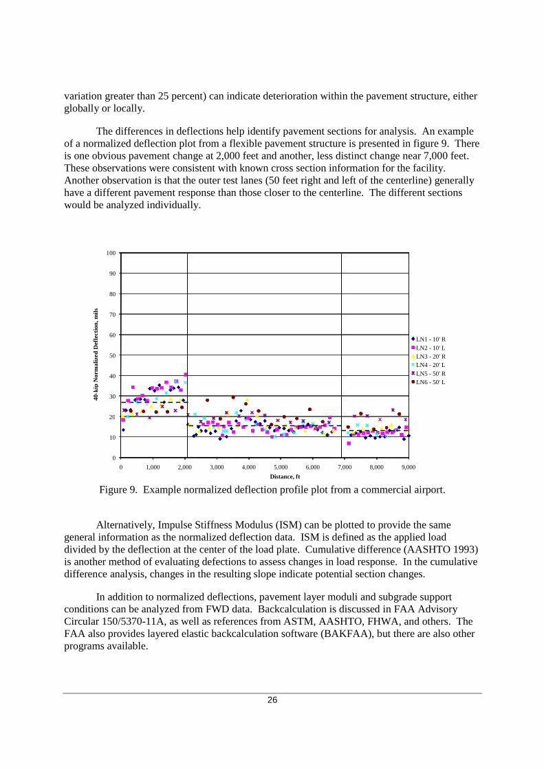
Figure ES-1. Potential existing pavement modulus adjustment based on effective condition....... viii Figure 1. Distribution of wheel load in an HMA pavement ....................................................3 Figure 2. Illustration of elastic layer theory used to estimate critical tensile strain in
HMA overlay (εOV) and/or original HMA surface layer (εHMA). .............................5 Figure 3. Option for incorporating HMA fatigue as failure criterion .....................................9 Figure 4. FAARFIELD screen illustrating cumulative CDF calculation ..............................11 Figure 5. FAARFIELD flexible pavement design screen .....................................................13 Figure 6. FAARFIELD flexible overlay design screen .........................................................14 Figure 7. Rigid pavement failure curve .................................................................................15 Figure 8. Schematic of HMA overlay evaluation and design process ..................................19 Figure 9. Example normalized deflection profile plot from a commercial airport ...............26 Figure 10. Portable seismic pavement analyzer (left) and its sensor unit (right)
(Nazarian et al. 2006) .............................................................................................29 Figure 11. FAARFIELD traffic data input ..............................................................................39 Figure 12. Potential existing pavement modulus adjustment based on effective
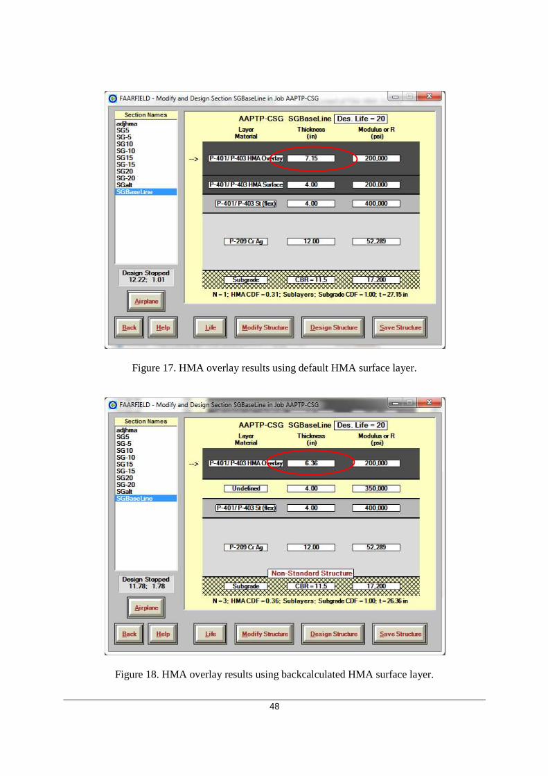
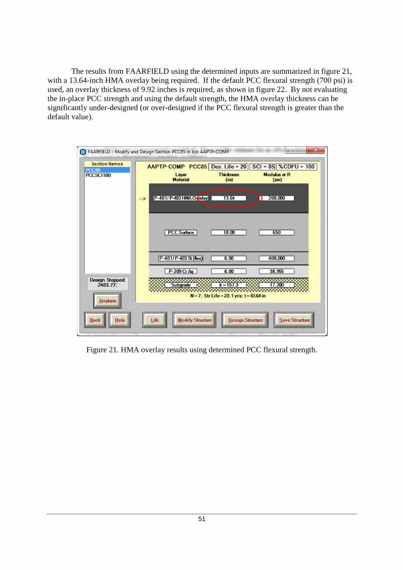
condition ................................................................................................................41 Figure 13. Selection of running HMA fatigue check in FAARFIELD ...................................46 Figure 14. Existing flexible pavement layer inputs in FAARFIELD......................................46 Figure 15. Using “undefined” layer to input backcalculated surface layer modulus ..............47 Figure 16. Using “undefined” layer to input effective surface layer modulus ........................47 Figure 17. HMA overlay results using default HMA surface layer ........................................48 Figure 18. HMA overlay results using backcalculated HMA surface layer ...........................48 Figure 19. HMA overlay results using effective HMA surface layer .....................................49 Figure 20. Existing composite pavement layer inputs in FAARFIELD .................................50 Figure 21. HMA overlay results using determined PCC flexural strength .............................51 Figure 22. HMA overlay results using default PCC flexural strength ....................................52
v
LIST OF TABLES Table ES-1. Summary of traditional evaluation techniques and their contribution to the HMA
overlay design process ........................................................................................... xi
Table ES-2. Summary of corrective action and HMA overlay design adjustments ................. xii
Table 1. Pavement remaining life based on CDF value (FAA 2009) ..................................10 Table 2. Available stabilized base layers in FAARFIELD (from Table 3-8,
FAA 2009) .............................................................................................................12 Table 3. Rigid pavement distresses used to calculate SCI (from Table 4-1,
FAA 2009) .............................................................................................................15 Table 4. Summary of advantages and disadvantages of traditional evaluation
techniques ..............................................................................................................18 Table 5. Distress types and primary distress categories .......................................................21 Table 6. HMA pavement distress types used to calculate the SCI ......................................22 Table 7. Engineering/performance properties targeted by corrective and mitigative
techniques ..............................................................................................................32 Table 8. Summary of corrective action design adjustments ................................................34 Table 9. Summary of estimated performance of crack mitigation techniques and
corresponding equivalent HMA thicknesses .........................................................35 Table 10. Summary of applying traditional evaluation techniques .......................................36 Table 11. Typical modulus values and ranges for paving materials ......................................40 Table 12. Summary of commercial airport traffic mix used in sensitivity analysis ..............44 Table 13. Summary of flexible pavement cross sections .......................................................44 Table 14. Summary of example pavement layer properties ...................................................45 Table 15. Summary of composite pavement cross section and properties ............................50
vi
ABSTRACT
The latest Federal Aviation Administration (FAA) Advisory Circular on airfield pavement design, Advisory Circular 150/5320-6E, is based on a mechanistic-empirical approach toward the analysis of pavement structures. The approach to hot-mix asphalt (HMA) overlay design is still based on a structural deficiency approach to limit subgrade rutting (and HMA fatigue but not by default), but takes a different approach in modeling the pavement for analysis. With layered elastic analysis for flexible pavements and finite element method for rigid pavements, it is now more important to appropriately characterize the contribution of existing pavement layers in the design. One aspect of the FAA airport pavement HMA overlay design that is unusually vague in the new procedure is the characterization of the structural contribution of an existing HMA pavement in the overlay design process. Verbatim guidance on this topic consists of the following:
• The existing flexible pavement is characterized by assigning the appropriate thicknesses and moduli of the existing layers.
• Subgrade and subbase properties can be measured by conducting NDT (nondestructive testing).
However, there is little guidance on characterizing the condition, and therefore the structural contribution, of the existing stabilized layers. The incorporation of repair and distress mitigation techniques is also not clearly defined. This research project reviews current HMA overlay design procedures, assesses the sensitivity of design inputs in the FAA HMA overlay design procedures, discusses the general characterization of an existing pavement and repair and mitigation techniques in the design of HMA overlays, and provides recommendations for potential clarifications in the design procedure. Recommendations are also discussed for aspects of the design procedure that require additional research. The project report is contained in two volumes: Volume I represents the Technical Report, with detailed summary and discussion of the activities performed and recommendations, and Volume II, Guidelines for HMA Overlay Design, provides a brief summary of these aspects and provides a proposed framework for assessing existing pavements and for designing HMA overlays.
vii
SUMMARY OF FINDINGS
The latest Federal Aviation Administration (FAA) Advisory Circular on airfield pavement design, Advisor Circular 150/5320-6E (2009), incorporates a mechanistic approach for the analysis of pavement structures. The approach to hot-mix asphalt (HMA) overlay design is based on a thickness deficiency approach, in which the design thickness of an HMA overlay is the difference between the required thickness of a new HMA pavement designed to carry the projected aircraft traffic and the existing pavement structure. Depending on the nature of the existing pavement—HMA, portland cement concrete (PCC), fractured PCC, or composite, for example—there are procedures to characterize the structural contribution of the existing pavement. Essentially, these procedures reduce the overall structural capacity contribution of the existing pavement based on the pavement’s structural condition.
For existing PCC pavements, the overlay design procedure uses the Structural Condition Index (SCI) and Cumulative Damage Factor Used (CDFU) to characterize the structural capacity of the existing pavement, and there is specific guidance in the Advisory Circular to determine these inputs. The characterization of the structural contribution of an existing HMA pavement, however, is rather vague. Guidance in the Advisory Circular on this topic consists, word for word, of the text in the following two bullets:
• The existing flexible pavement is characterized by assigning the appropriate thicknesses and moduli of the existing layers.
• Subgrade and subbase properties can be measured by conducting NDT [nondestructive testing].
However, there is little guidance on characterizing the condition, and therefore the structural contribution, of the existing stabilized layers. Because the HMA overlay thickness determination is based on the existing structural deficiency, this is an important omission. The research conducted under Airfield Asphalt Pavement Technology Program (AAPTP) Project 06-07, Assessment of FAA HMA Overlay Procedures, helps remedy this shortcoming. The results of this study: (1) provide recommendations to modify the elastic layer HMA overlay design procedure, and (2) develop guidelines for characterizing an existing HMA layer(s) and possible repair treatments and for incorporating the results into FAA’s HMA overlay design procedure.
In addition to the typical failure mode of rutting in the subgrade, this study also evaluates other potential failure modes, including deformation in other layers, fatigue of the HMA layer(s), reflective cracking, and thermal cracking. While there have been models developed for these other failure modes, they generally have not been widely accepted or used in practice (except for fatigue cracking). A simplified method of assessing the potential for reflection cracking (Sousa et. al, 2005) has potential of providing a secondary design check. Materials-related performance (such as in-layer rutting) should be evaluated using laboratory methods until validated models are developed.
Traditional pavement evaluation techniques to characterize the existing pavement structure, including visual, destructive, and non-destructive techniques, are reviewed to assess the types of data collected and their potential use in HMA overlay design. A visual assessment is
viii
one of the easiest and most effective means of collecting pavement condition data. However, the data are not directly used in thickness design. While visual assessment data are only used on a limited basis, they can be used to determine what other evaluation techniques are needed to adequately assess the distress mechanism(s), to assess potential adjustments to other design inputs, and to establish the need for corrective action or selection of a rehabilitation method other than HMA overlay.
Non-destructive testing methods often allow a greater amount of data to be collected and analyzed (compared with destructive methods), which can be an advantage over a destructive testing method such as coring. However, it is often beneficial to perform both destructive and non-destructive testing, as the results from these two approaches offer the greatest coverage over a project area and a means to validate results. Table ES-1 provides a brief summary of the anticipated information obtained by traditional evaluation techniques and when each technique may be applicable.
There are many corrective and mitigative techniques and methods that can be used to repair existing distress and improve HMA overlay performance. A brief summary of these techniques, along with ways to deal with such measures in the overlay design process, are summarized in table ES-2.
Based on this study and corresponding guidelines, the following factors should be considered by the designer during the design of an HMA overlay:
• Obtain as accurate of traffic data as possible, as the pavement design thickness is extremely sensitive to aircraft weight.
• Use one or more pavement evaluation techniques to determine existing layer moduli. Assess the impact of other data collected during evaluation (such as layer condition, bonding, and so on).
• Consider adjustment of NDT-determined layer moduli for overall condition and effects of repairs (or not performing repairs). One potential scheme, based on Pavement Condition Index (PCI) data, is illustrated in figure ES-1.
Figure ES-1. Potential existing pavement modulus adjustment based on effective condition.
ix
Table ES-1. Summary of traditional evaluation techniques and their contribution to the HMA overlay design process.
Evaluation Technique Anticipated Design Information Suggested Use
PCI/SCI
• Assessment of condition (structural and functional) and cause(s) of deterioration.
• Adjustment of layer moduli based on global condition (before or after pre-overlay repairs).
Should be performed as part of all projects.
Coring and Boring
• Layer thicknesses and types. • General layer condition to assess the
need to adjust moduli.
Ideally performed as part of all projects, but especially for projects showing any structural or materials-related deterioration or when there is a significant change in the aircraft mix.
DCP
• Unbound layer moduli correlated to blow counts (or CBR).
Relatively inexpensive means of obtaining unbound layer strength properties. Consider when coring is already being performed and when FWD or PSPA testing will not be performed.
Laboratory Testing
• Unbound layer properties (type and CBR).
• PCC flexural strength correlated to core testing (compressive or splitting tensile strength).
• HMA testing less common but can provide layer moduli.
• Microscopic analysis of bound materials to assess materials-related deterioration.
Use in conjunction with coring and boring. Testing of unbound material properties is not as critical, unless stability is a concern. Bound material testing should be considered when structural- or material-related deterioration are present; can also provide correlation information for FWD and PSPA testing.
FWD
• Provide modulus for pavement layers and subgrade.
• Identify localized areas of weakness or poor support.
• Can sometimes detect delaminations in pavement structure.
Should be used when structural deterioration is apparent and when material properties of layers are not obtained through other means.
GPR
• Provides layer thicknesses. • Can sometimes detect delaminations or
voids in pavement structure.
Provides large coverage (compared to cores) and should be considered if significant thickness variations or delaminations are suspected. Can provide location-specific thickness data for FWD data analysis, identify substantial voids, and indicate areas of saturation.
PSPA
• Provides surface layer modulus. • Can sometimes detect delaminations in
pavement structure.
Particularly useful in assessing surface layer variability, such as caused by structural or materials-related deterioration.
x
Table ES-2. Summary of corrective action and HMA ovelay design adjustments.
Category Corrective Action Proposed Adjustment
Localized Maintenance and Repair
Crack sealing Adjustment of existing modulus based on estimated condition after repair.
Partial-depth patching Adjustment of existing modulus based on estimated condition after repair
Full-depth patching Adjustment of existing modulus based on estimated condition after repair
Modification of Existing HMA Pavement
Cold milling
Milling depth should remove as much surface distress as possible; reduce existing pavement thickness in design accordingly; adjustment of existing modulus based on estimated condition after milling
Surface recycling Not commonly used; would modify existing layer modulus and potentially thickness
Surface leveling course Include with the determined overlay thickness
Stress/Strain Relieving Interlayers
Stress-absorbing membrane interlayer (SAMI)
Equivalent thickness in external reflective cracking check
Equivalent thickness in external reflective cracking check
HMA Overlay Reinforcement
Steel or wire fabric Equivalent thickness in external reflective cracking check
Geogrids Equivalent thickness in external reflective cracking check
Geosynthetic fabric Equivalent thickness in external reflective cracking check
Crack Arresting or Cushion Layers
Aggregate Not recommended
Asphalt-aggregate Model appropriate layer thickness and modulus
Bond Breakers Not recommended HMA Overlay Mixture Modification
Rubber-modified asphalt binder No adjustment Polymer-modified asphalt binder No adjustment Soft (low-viscosity) asphalt binder Not recommended
xi
• Use determined modulus for the existing HMA layer(s) if greater than approximately a 20 percent difference from the default values. Values with less difference will have minimal impact on the overall design thickness.
• For composite pavement: – Determine concrete flexural strength from evaluation. – Assess the effective thickness of existing HMA overlay in composite pavements. – Assuming a CDFU of 100 percent and establishing an appropriate SCI is likely a
reasonable approach for composite pavements.
• Use the default modulus for the HMA overlay.
• Use representative layer moduli unless there is a significant difference in loadings during different seasonal periods.
• Perform external design checks for reflective cracking, including accounting for repair and mitigation techniques being considered.
• Consider assessment of in-layer rutting of HMA if loading conditions are unique or if there is a local history of HMA materials rutting.
xii
1
CHAPTER 1. INTRODUCTION TO GUIDELINES
BACKGROUND
Airfield hot-mix asphalt (HMA) overlay design procedures include both empirical (based on observation and experience) and mechanistic-empirical (based on material properties and measured responses) methods. Up through the Federal Aviation Administration’s (FAA’s) Advisory Circular (AC) 150/5320-6D (FAA 1995), the FAA’s methods were primarily empirical, with the California Bearing Ratio (CBR) method and Westergaard edge-stress analysis used for flexible and rigid (and composite) pavement design, respectively. These methods served as the basis of the FAA’s “nomograph” (or conventional) design procedure. For flexible pavement design, the performance criterion was based on controlling subgrade rutting, while rigid pavement performance was based on limiting slab cracking.
Mechanistic-empirical (M-E) design, as implemented in FAA’s LEDFAA program and continued in Advisory Circular 150/5320-6E (FAA 2009) and their new FAARFIELD program, correlates calculated critical pavement stresses and strains to empirical performance models. The move to mechanistic principles also incorporates additional material properties into the design procedure, including elastic modulus and Poisson’s ratio. Traffic loadings are also handled differently: the procedure no longer uses a “design aircraft” concept to characterize the entire aircraft mix; instead each specific aircraft loading is analyzed to determine its contribution to pavement damage.
Although stresses and strains are calculated in FAARFIELD, the performance criteria are essentially the same as they were in Advisory Circular 150/5320-6D: subgrade rutting for flexible pavement design and slab cracking for rigid pavement design. HMA fatigue is also analyzed in FAARFIELD but is not the default criterion (i.e., the user can view the results, but it does not affect the resulting design thicknesses). These performance criteria are common among the available airfield pavement design procedures.
In the FAA’s design procedure, overlay design generally uses the same models and performance criteria as it does for new pavement design. However, this highlights a shortcoming of the FAA’s procedure, both for new design and especially for overlay design, in that there are actually a multitude of performance measures and deterioration mechanisms that are in play, but the FAA procedure currently only evaluates a few of these mechanisms. Performance measures as they relate to flexible pavements, including HMA overlays, that can be considered, but are not included in the FAA overlay design procedures, include the following:
• Permanent deformation (rutting) within the HMA layer. • Permanent deformation within the unbound aggregate layer. • Reflective cracking. • Thermal HMA cracking. • Top-down HMA cracking.
There has been relatively limited research and development of performance models for these other performance measures for airfield pavements. Of these, reflective cracking and HMA layer deformation are perhaps the ones most commonly associated with poor HMA
2
overlay performance. HMA layer deformation is typically not modeled, as it is assumed to be addressed by proper mix design. Reflective cracking is a complex mechanism that develops due to both load and climatic factors, and there are several possible methods of addressing it.
A specific need for the design of HMA overlays is the characterization of the existing pavement and how that condition (or repairs prior to overlay placement) will affect the performance of the overlay. The guidance contained within FAA’s design procedure for incorporating the condition of existing flexible pavements is limited at best. There is also little guidance on how pre-overlay repairs can be accounted for in the design process. Because determination of the HMA overlay thickness is based on the structural capacity (or deficiency) of the existing pavement, this is an important omission and the impetus for this research study and corresponding guidelines.
PURPOSE OF THIS GUIDE
This Guide for HMA Overlay Design is intended to supplement FAA Advisory Circular 150/5320-6E and FAARFIELD program, providing practicing airport pavement designers with guidelines for evaluating existing pavement conditions and incorporating the results into the HMA overlay design procedure. Guidance in this document is limited to HMA overlay design of asphalt-surfaced pavements (i.e., overlays on existing flexible pavements [AC and AAC] and overlays on existing composite pavements [APC]).
This Guide represents Volume II of the results from AAPTP Project 06-07, Assessment of FAA HMA Overlay Procedures. It presents recommendations for characterizing an existing HMA surface, summarizes common pre-overlay repair and mitigative techniques, and provides suggestions on ways the collected data and techniques may be incorporated into the HMA overlay design procedure in FAA’s Advisory Circular 150/5320-6E.
More detailed information on these topics can be found in the Volume I report, which includes the following topics:
1. A review of overlay design procedures and practices for airfields. 2. A sensitivity analysis on the FAARFIELD overlay design methodology. 3. A summary of common methods for assessing existing HMA pavement conditions,
limiting values, and possible alternative corrective actions, including recommendations for how to handle the condition of existing or modified pavements within the overlay design procedure.
4. Recommendations for incorporating proposed changes into both Advisory Circular 150/5320-6E and the accompanying FAARFIELD computer program.
This volume provides condensed guidelines for applying the findings from this study into HMA overlay design using the FAA pavement design procedure. It consists of the following chapters:
CHAPTER 2. OVERVIEW OF HMA OVERLAY DESIGN INTRODUCTION
HMA overlays serve a wide variety of purposes ranging from addressing a surface problem such as poor skid resistance to providing additional structural capacity on a pavement that receives heavy traffic loads and/or high traffic volumes. In addition, with proper attention to traffic and environmental effects when developing structural designs and mix designs, HMA overlays can be applied successfully over a wide range of climate and support conditions. HMA overlays are probably the most commonly selected rehabilitation alternative in most airports’ pavement management plans. Because of the widespread use of HMA overlays and minimal guidance in the FAA Advisory Circular, it is important to understand the pavement behavior and failure mechanisms in order to then select appropriate inputs (and understand how these inputs may influence the performance of the HMA overlay) for designing an HMA overlay.
HMA OVERLAY PERFORMANCE AND FAILURE MECHANISMS
HMA Overlay Pavement Behavior
An HMA overlay is generally assumed to be completely bonded to the underlying HMA pavement structure. If designed and constructed properly, the overlay should behave similarly to the HMA surface layer of a new pavement. There are three primary factors that affect the behavior of an HMA pavement and an HMA overlay, as discussed below.
Aircraft Gear Loading
Figure 1 shows a wheel load being applied to a pavement surface (through the tire) at a uniform vertical pressure. As illustrated by the arrows, the pavement structure distributes the applied load through the structure and to the natural soil so that the maximum pressure on the subgrade soil is considerably less than the vertical pressure at the surface. In the process of distributing the load, various states of stress are built up within the various layers, which can lead to the overall deterioration of the pavement, such as fatigue and permanent deformation.
Wheel Load
Hot-mix asphalt
Base
Subbase
Natural soil
Figure 1. Distribution of wheel load in an HMA pavement.
4
Temperature
Temperature influences HMA performance in two ways. First, fluctuations in temperature result in expansion and contraction, which can lead to the development of compressive and tensile stresses. The tensile stresses over time can lead to the development of cracks (i.e., thermal cracking). Secondly, HMA is a temperature-dependent material and fluctuations in temperature result in changes to HMA material properties (most notably the elastic modulus). Consequently, increases in HMA temperature result in decreases in stiffness and resistance to permanent deformation, while temperature drops increase HMA stiffness and can make it more brittle.
Moisture
Moisture affects materials and, therefore, pavement behavior primarily in two ways. In unbound (and some bound) layers, moisture acts as a lubricant between aggregate particles. By permitting more freedom of movement between aggregate particles, it effectively weakens the material and reduces the pavement’s load-carrying capacity. Secondly, in certain asphalt-stabilized layers (including the HMA surface) with hydrophilic aggregates, moisture can cause a separation of the asphalt from the aggregate (i.e., stripping). Stripping weakens the material and reduces the overall load-carrying capacity of the pavement.
Typical Failure Mechanisms and Distress Manifestations
The two pavement responses generally considered in the current FAA design procedure of flexible pavements and HMA overlays, as well as many other design procedures, are the vertical compressive strain at the top of the subgrade and the horizontal tensile strain at the bottom of the HMA layer(s). These responses relate to the development of subgrade permanent deformation (rutting) and HMA fatigue (alligator) cracking, respectively, which are discussed further.
Permanent Deformation
Permanent deformation (or rutting) refers to a progressive process whereby the accumulation of small amounts of load-induced permanent deformation in one or more layers ultimately leads to a pavement surface depression in the wheel paths (i.e., ruts). The vertical compressive stresses on the HMA surface, base, and subgrade soil can contribute to the permanent deformation of the layer(s) beneath them. However, the current FAA design procedure only considers rutting on the subgrade.
The evaluation of the existing pavement needs to assess where the permanent deformation is occurring. For example, if deformation exists only in the HMA surface layer, then any one or combination of the following factors could be the cause:
• The HMA surface layer was overloaded.
• Loadings were applied during a hot period (when the HMA layer was “soft”).
• The HMA has a mix stability problem.
• The HMA has a temperature susceptibility problem.
• The HMA surface has been contaminated, such as by fuel.
5
Deformation may also be attributed to the base/subbase layers, or if the total rutting at the surface exists in all layers down to the subgrade, then the problem is likely attributed to one of the following reasons:
• The pavement structure is too thin for the applied loads.
• The subgrade is naturally weak (or consists of a soil in which there are regularly high moisture contents).
Determining where the rutting is occurring will influence the selection of the type of rehabilitation to be performed.
HMA Fatigue
The basic concept of most mechanistic approaches to overlay design is that the design overlay thickness will limit fatigue damage in the existing pavement and/or overlay to an acceptable level over the design period. The existing pavement and overlay are modeled using elastic layer theory or finite element analysis to estimate the critical fatigue responses associated with the design load. For flexible pavements with an HMA overlay, the critical responses are the maximum tensile strains at the bottom of the original HMA surface layer (εHMA) and HMA overlay (εOV), as depicted in figure 2.
Natural Soil
Subbase
Base
OriginalHMA Surface
Layer
HMA OverlayTH
TH
TH
TH
E
E
E
E
V
V
V
V
1
2
3
4
1
2
3
4
1
2
3
4
ThicknessYoung’s Modulus
Poisson’sRatio
ε
ov
HMA
εSimulated
Design Axle Load
Figure 2. Illustration of elastic layer theory used to estimate critical tensile strain in HMA overlay (εOV) and/or original HMA surface layer (εHMA).
The mechanism of fatigue refers to a progressive process whereby a bound layer in the HMA pavement structure undergoes repeated applications of stress (or strain) until it eventually cracks. No single load is enough to exceed the strength of the bound material, yet the accumulation over time eventually wears out or fatigues the material. The repeated generation of tensile strains at the bottom of the HMA surface layer resulting from the application of a wheel load first causes the initiation of a crack at the bottom of the layer. Continued load repetitions ultimately cause the crack to propagate from the bottom to the surface. The presence of fatigue
6
cracking is an indication of structural failure and the loss of structural (load-carrying) capacity in the pavement. Once it initiates, fatigue cracking can progress at a very rapid rate as the pavement becomes weaker and weaker. Thus, if otherwise uniform areas of pavement begin to develop fatigue cracking, the rest of the pavement is likely not far behind. This should have some bearing on the selection of an appropriate rehabilitation alternative.
It should also be noted that fatigue cracking does not always initiate in the HMA surface layer for new flexible pavements. If a stabilized base course exists, its stiffness may be great enough such that tensile strains can be generated at the bottom of this layer and fatigue cracking may initiate there. Likewise, fatigue cracking of an HMA-overlaid pavement can initiate in the original surface or base course rather than in the overlay itself.
Other Failure Mechanisms and Distress Manifestations
Two of the most common failure mechanisms specifically for HMA overlays are reflective cracking and in-layer permanent deformation. These mechanisms are discussed below.
Reflective Cracking
Reflective cracks appear on the surface of an overlay above joints or cracks in the underlying pavement layer. Reflective cracking occurs in nearly all types of overlays, but is most often a problem in HMA overlays of HMA pavements with existing thermal cracks and in HMA overlays of jointed PCC pavements. Reflective cracking occurs when horizontal and vertical movements at the joints and cracks in the underlying pavement create high stress concentrations in the overlay. These movements at joints and cracks are caused by a combination of low temperature and traffic loads (Smith et al. 1984).
Reflective cracking leads to increased infiltration of surface water into the pavement system, which in turn weakens the supporting layers. Over time, reflective cracks will also deteriorate and spall, decreasing the pavement’s serviceability.
The key to eliminating reflective cracking is to eliminate the movements and stresses produced in the HMA overlay at existing joints and cracks. However, it is highly unlikely that these deformations and stresses can ever be completely eliminated; the most that can be achieved is a reduction in the magnitude of these responses and the rate of appearance and severity of the reflective cracks.
Although attempts have been made to develop a comprehensive design procedure that addresses the problem of reflective cracking (Seeds, McCullough, and Carmichael 1985; Majidzadeh et al. 1987); to date no procedure has received widespread acceptance. Design issues regarding reflective cracking consider the following factors:
• The rate of reflective cracking through the overlay.
• The amount and rate of deterioration of the cracks after cracking occurs.
• The amount of water that can infiltrate through the cracks.
7
While each factor is important, the second factor is considered the most cost-effective in terms of minimizing the long-term impacts on pavement performance. If the crack severity can be limited, sealing the crack is easier and the contribution of crack deterioration to pavement condition and roughness is greatly reduced. This is the primary reason that pre-overlay repairs and treatments are used.
AAPTP Project 05-04, Techniques for Mitigation of Reflective Cracking, provides guidance and recommendations to manage and design rehabilitation strategies of airfield pavements for mitigating reflection cracks (Von Quintus, et al. 2009). The guidance includes selection and use of materials and treatment methods to increase the time to the occurrence of reflective cracks in HMA overlays of rigid, flexible, and composite pavements. It also provides guidance on the effectiveness of different treatments for minimizing reflection cracking from experience gained of various organizations (both airfield and highway uses) and an evaluation of numerous airfields that have used the different strategies.
Permanent Deformation
Permanent deformation (rutting) may occur in HMA overlays, sometimes within the first few years of overlay construction. This has become a growing concern at many airports, due to the continued increase in aircraft weights, gear weights, and tire pressures.
As discussed previously, rutting observed at the surface can be the accumulation of deformation in one or more pavement layers. And as previously noted, deformation of the subgrade (and the resultant rutting that would be observed on the pavement surface) is generally considered in airport design and is the primary failure mode checked in the FAA design procedure. However, it is assumed no rutting occurs in other pavement layers. Rutting of the subgrade is typically caused by shear deformation of the upper subgrade, and many models have been developed to characterize this deformation in design.
However, rutting also commonly occurs in the HMA and unbound granular layers. Surface rutting is especially problematic on airfields where static aircraft loads are applied, such as on aprons, at other parking areas, at hold lines, and on other areas where aircraft stacking occurs. Surface rutting occurs when the HMA mixture exhibits low stiffness under loading. Critical factors to consider in minimizing rutting include the angularity of the coarse and fine aggregate, aggregate gradation, the rut-resistance of the mix design, the proposed field compaction efforts, selection of asphalt binder, asphalt content, and volumetric mix properties. While there has been some work to develop models for HMA surface deformation, they have not generally been implemented yet.
Testing at the FAA’s full-scale testing facility has revealed significant contribution to total rutting from the P-209 and P-154 unbound materials (Kim and Tutumluer 2006). Under heavy loading, additional densification or shear failures can occur within the aggregate layers, particularly thick aggregate layers. Kim and Tutumluer (2006) developed an aggregate layer rutting model, but it has not yet been thoroughly validated.
8
FAA HMA OVERLAY DESIGN
In order to best make use of these guidelines, it is first important to understand the FAA design procedure. This section presents the history of FAA pavement design, and then focuses on the required inputs and design approach of FAA’s current procedure. This understanding is critical to make effective use of the specific guidelines presented in subsequent chapters.
History of FAA Pavement Design
The empirical airfield pavement design procedure described in FAA Advisory Circular 150/5320-6D (FAA 1995) and previous versions has been the standard for many years, although its origins lie in research and empirical observations on the bearing capacity of roadways and airfields conducted over the last 60 years. The structural design of HMA overlays of airfield pavements is included in that Advisory Circular procedure. The approach to overlay design is based on a thickness deficiency approach, in which the design thickness of an HMA overlay is the difference between the required thickness of a new HMA pavement designed to carry the projected aircraft traffic and the existing pavement structure. Depending on the nature of the existing pavement (HMA, PCC, fractured PCC, or HMA over PCC [or composite], for example), there are procedures to characterize the structural contribution of the existing pavement. Essentially, these procedures reduce the contribution of the existing pavement to the overall load-carrying capacity of the pavement based on its actual structural condition.
The 1995 pavement design Advisory Circular 150/5320-16, Airport Pavement Design for the Boeing 777 Airplane was FAA’s first attempt at incorporating M-E concepts into the design and analysis of airfield pavement structures. That procedure was only for the design of pavements having the Boeing 777 in the traffic mix, and it used layered elastic analysis for both flexible and rigid thickness design. Specifically, that Advisory Circular introduced the FAA’s Layer Elastic Design FAA (LEDFAA) software, in which M-E analysis is used to calculate critical load-induced strains, which are then used to develop pavement designs. The M-E concepts were later incorporated into Advisory Circular 150/5320-6D in 2004 with change 3 to the document.
Current Design Procedure, FAA AC 150/5320-6E
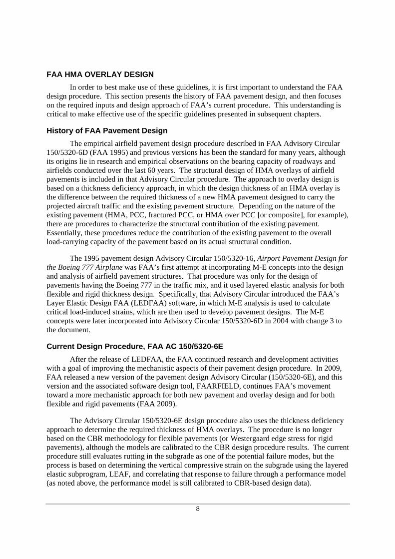
After the release of LEDFAA, the FAA continued research and development activities with a goal of improving the mechanistic aspects of their pavement design procedure. In 2009, FAA released a new version of the pavement design Advisory Circular (150/5320-6E), and this version and the associated software design tool, FAARFIELD, continues FAA’s movement toward a more mechanistic approach for both new pavement and overlay design and for both flexible and rigid pavements (FAA 2009).
The Advisory Circular 150/5320-6E design procedure also uses the thickness deficiency approach to determine the required thickness of HMA overlays. The procedure is no longer based on the CBR methodology for flexible pavements (or Westergaard edge stress for rigid pavements), although the models are calibrated to the CBR design procedure results. The current procedure still evaluates rutting in the subgrade as one of the potential failure modes, but the process is based on determining the vertical compressive strain on the subgrade using the layered elastic subprogram, LEAF, and correlating that response to failure through a performance model (as noted above, the performance model is still calibrated to CBR-based design data).
9
FAARFIELD also allows the option of evaluating the horizontal tensile strain at the bottom of the HMA layers to investigate the potential for fatigue cracking of the HMA. This failure mode is turned off by default, but the user can enable this failure mode by deselecting the “No AC CDF” checkbox within the FAARFIELD Options screen, as shown in figure 3.
Figure 3. Option for incorporating HMA fatigue as failure criterion.
FAARFIELD (version 1.305) has the capability to evaluate the strain of the HMA layers (such as the HMA overlay and a stabilized base layer) for fatigue failure, and all bituminous layers are assumed to be bonded to each other. This is different than other design procedures that evaluate fatigue failure, such as the Asphalt Institute, which evaluate the strain at the bottom of the lowest stabilized layer (not necessarily the bottom of the surface layer). Because the HMA surface and stabilized base layers are assumed to be bonded in FAARFIELD and the surface modulus is set at 200,000 psi, the fatigue failure criterion seldom, if ever, controls predicted performance (note: this is further illustrated by the results of the sensitivity analysis described in Chapter 3 of Volume I, Assessment of FAA HMA Overlay Design Procedures). While fatigue failure does not typically control the design, running the design check in the FAARFIELD software is beneficial and does not add significant time to the processing with the speed of current computers.
For the design of an HMA overlay of PCC pavements, the procedure uses the Structural Condition Index (SCI) to provide an objective measure of the existing PCC pavement’s condition (as opposed to the Cb condition factor used in 150/5320-6D). However, a similar
10
method is not available to assess the condition of an existing HMA pavement to be overlaid. In fact, the Advisory Circular offers only the following guidance on characterizing the existing HMA pavement:
• “The existing flexible pavement is characterized by assigning the appropriate thicknesses and moduli of the existing layers.”
• “Subgrade and subbase properties can be measured by conducting NDT [nondestructive testing].”
There is little guidance on characterizing the condition, and therefore the structural contribution, of the existing pavement layers. Because determination of the overlay thickness is based on the existing structural capacity, this is an important omission and the impetus for this research study and corresponding guidelines.
Another major change is the way in which the procedure characterizes traffic. The procedure in 150/5320-6E analyzes each specific aircraft loading to determine its contribution to pavement damage, using a cumulative damage factor (CDF) to represent the life of the pavement (rather than the “design aircraft” concept). For a single airplane and constant departures, the CDF is expressed as the ratio of the applied load repetitions to the allowable load repetitions or coverages to failure (as determined from the applicable performance model). Multiple airplane types are accounted for by applying Miner’s rule. Table 1 shows the relationship between CDF and the remaining life of the pavement. Essentially, a pavement has used up its life when the CDF equals 1.0 (or 100 percent).
Table 1. Pavement remaining life based on CDF value (FAA 2009).
CDF Value Pavement Remaining Life 1 The pavement has used up all of its design life
< 1 The pavement has some life remaining, and the value of CDF gives the fraction of the life used.
> 1 The pavement has exceeded its design life
Within the program, CDF is calculated for each 10-inch strip along the pavement over a total width of 820 inches (82 strips). Figure 4 illustrates this concept, in which the cumulative CDF is computed as the sum of the CDF from each individual aircraft over each 10-inch strip. Using the pass-to-coverage ratio for each aircraft and a normal distribution of aircraft wander with a standard deviation of 30.435 inches, CDF is computed for all 82 strips. FAARFIELD iterates by changing the layer thickness (the subbase thickness for new design and the HMA overlay thickness for overlay design) until the maximum CDF of any strip is equal to 1.0.
11
Figure 4. FAARFIELD screen illustrating cumulative CDF calculation. The following inputs are required for new flexible pavement design using FAARFIELD:
• Design life – Typically 20 years for FAA standard design.
• Traffic – Aircraft type, weight, and volume for each aircraft (note: FAARFIELD has an aircraft library that includes other properties, such as gear type, wheel spacing, and tire pressure).
• HMA surface – A minimum surface thickness of 4 inches is required for pavements with aircraft weighing more than 30,000 lbs. The HMA surface modulus is fixed at 200,000 psi (this value was conservatively selected by FAA to represent a pavement temperature of 90 °F).
• Stabilized base course – A stabilized base course is required for pavements being designed to handle aircraft exceeding 100,000 lbs. The available stabilized bases in FAAFIELD are presented in table 2, along with the default modulus (or range of allowable values) and Poisson’s Ratio. The materials conforming to FAA’s construction specification have a fixed modulus in FAARFIELD. If another material or modulus is desired, a “variable” layer must be used.
• Unstabilized base course – The standard aggregate base course for FAA flexible pavement design is a P-209, crushed aggregate base course. The modulus of this layer is automatically calculated in FAARFIELD using the “Modulus” procedure developed by the U.S. Army COE (UFC 3-260-02, Army 2001).
• Subbase course – The standard subbase material is a P-154, aggregate subbase course. The modulus of this layer is also internally calculated similar to the aggregate base layer. For pavements required to handle aircraft exceeding 100,000 lbs (in which case a stabilized base course is required), the Advisory Circular recommends a higher quality subbase (such as P-208 or P-209) be used as the subbase course.
12
• Subgrade support condition – Although the program uses the elastic modulus (E) of the subgrade in its calculations, either CBR or E can be entered, and FAARFIELD automatically calculates the other parameter using the following correlation:
xCBRE 1500= (Eq. 1)
Table 2. Available stabilized base layers in FAARFIELD (from Table 3-8, FAA 2009).
Base Layer Modulus, psi Poisson’s Ratio Stabilized (Flexible) Variable P-401/P-403 Asphalt
150,000 – 400,000
400,000 0.35
Stabilized (Rigid) Variable P-304 Cement Treated Base P-306 Econocrete Subbase
250,000 – 700,000
500,000 700,000
0.20
In a new HMA design, the required thickness of the base course (unbound and stabilized) can be automatically determined (note: the base thickness can be set by the user by deselecting the “Enable Automatic Base Design” checkbox in the Options window). The P-209 thickness required to protect a subbase with CBR of 20 (assumed to be P-154 material) is automatically determined in FAARFIELD, and then the P-209 base is converted to a stabilized base using an equivalency factor of 1.6 when designing for aircraft weighing more than 100,000 lbs.
Once these inputs are selected and entered into FAARFIELD, the design (at least from the user’s standpoint) is simple. After clicking the “Design Structure” button, the program performs an iterative process of adjusting the layer thicknesses and computing the CDF (for all 82 strips) until a CDF of 1.0 is reached.
Figure 5 shows the FAARFIELD screen after the design has been run. A few items on this screen are worth noting:
• The base thickness is determined automatically within FAARFIELD as the minimum thickness required to protect the subbase (unless this option is deselected in the Options window).
• The subbase thickness is what is designed for flexible pavement design. This is noted by the arrow on the left side of the pavement layers.
• Once the design is complete, the CDF will be approximately equal to 1.00, as noted at the bottom of the window.
Understanding the new flexible pavement design, the determination of an overlay thickness using FAARFIELD is a fairly easy process in which the user adds the overlay layer to the pavement cross section. When this is done, the arrow indicating the layer being designed will move to the overlay layer, as shown in figure 6. The other layers (type, thickness, and modulus) are set to represent the in-place properties of those materials. Then the user simply clicks the “Design Structure” button, and FAARFIELD calculates the required overlay thickness. The minimum allowable HMA overlay thickness is 2 inches. For this particular example, the required HMA overlay thickness is 5.5 inches.
The difficulty in the process is selecting the inputs to accurately model the in-place properties of the existing pavement layers. If materials adhering to FAA specifications are selected, the layer moduli are fixed as described previously. Unfortunately, the Advisory Circular does not provide much guidance on selecting these inputs.
For existing PCC pavements, the structural condition of the existing pavement is expressed in terms of the SCI. The SCI is derived from the Pavement Condition Index (PCI) and is essentially the summation of the structural elements of the PCI, as listed in Table 3. As with the PCI, the SCI scale ranges from 100 (no structural distress) to 0 (failed). An SCI of 80, corresponding to 50 percent of slabs in the traffic area exhibiting a structural crack, is FAA’s failure criterion. Because the SCI only considers the structural-related distresses, the SCI will always be equal to or greater than the PCI. The SCI replaces the Cb and Cr factors used to characterize the existing pavement condition in the 150/5320-6D procedure.
Table 3. Rigid pavement distresses used to calculate SCI (from Table 4
1 Used to describe a load-induced crack that extends only part of the way across does not include conventional shrinkage cracks due to curing or other non
The failure curve for PCC pavements is illustrated in figure cumulative fatigue damage used (CDFU)pavement (in which case the SCI is less than 100), the CDFU is defined as 100 percent. If there are no structural-related distressadditional step is required to determine where thCDFU). There are separate failure curves for CDFU for pavements with stabilized and aggregate bases. This is done within FAARFIELD by modeling the existing pavement in mode, rather than Design mode, to dvalue is then entered, and the overlay thickness is designed as usual.
Figure
15
. Rigid pavement distresses used to calculate SCI (from Table 4
induced crack that extends only part of the way across a slab. The SCInot include conventional shrinkage cracks due to curing or other non-load-
The failure curve for PCC pavements is illustrated in figure 7, which also incorporates cumulative fatigue damage used (CDFU). If load-related distresses are obspavement (in which case the SCI is less than 100), the CDFU is defined as 100 percent. If there
related distresses on the pavement (in which case the SCI is equal to 100), an additional step is required to determine where the pavement is on the failure curve (i.e., the CDFU). There are separate failure curves for CDFU for pavements with stabilized and aggregate bases. This is done within FAARFIELD by modeling the existing pavement in mode, rather than Design mode, to determine the CDFU for the traffic applied to date. This value is then entered, and the overlay thickness is designed as usual.
Figure 7. Rigid pavement failure curve.
. Rigid pavement distresses used to calculate SCI (from Table 4-1, FAA 2009).
Low, medium, high
medium, high Low, medium, high
Low, medium, high Low, medium, high
a slab. The SCI -related problems.
7, which also incorporates related distresses are observed on the
pavement (in which case the SCI is less than 100), the CDFU is defined as 100 percent. If there on the pavement (in which case the SCI is equal to 100), an
e pavement is on the failure curve (i.e., the CDFU). There are separate failure curves for CDFU for pavements with stabilized and aggregate bases. This is done within FAARFIELD by modeling the existing pavement in Life
etermine the CDFU for the traffic applied to date. This
16
SCI and CDFU are not currently used as indicators of the existing structural capacity of HMA pavements but potentially offer one method of characterizing the existing pavement.
SUMMARY
This chapter discusses HMA overlay design procedures in terms of pavement/overlay behavior and failure mechanisms, to help better understand the need to select appropriate inputs for designing an HMA overlay. HMA overlay design is predominantly controlled by subgrade rutting, but overlay performance is influenced by other distresses, including HMA fatigue, which is modeled in the latest FAA design software, and other distress mechanisms that are not currently modeled (such as reflective cracking and HMA and aggregate layer deformation).
The design approach and required inputs for FAARFIELD are presented in this chapter. The means and techniques for determining the inputs to represent the existing structure, as well as how to model the existing pavement in FAARFIELD, are discussed in subsequent chapters. Corrective and mitigative techniques and methods that can be used to repair existing distress and improve HMA overlay performance, along with ways to deal with such measures in the overlay design process, are also presented.
The HMA overlay design procedure implemented in FAARFIELD and Advisory Circular 150/5320-6E (FAA 2009) is based on a structural deficiency approach, but the analysis of stresses and strains in the pavement is much different than in previous FAA design methods. Inputs of layer type, thickness, and modulus are used to calculate the stresses and strains from aircraft in the mix and ultimately to determine the required HMA overlay thickness. Therefore, determining the condition and properties of the existing pavement structure is critical to account for existing pavement characteristics in the design procedure.
There are many destructive and non-destructive evaluation techniques available for determining layer properties. There is not necessarily a single, best alternative for every situation, but rather several methods should generally be used in combination depending on the specific circumstances. The goals of the evaluation methods should include the following:
• Estimating subgrade support.
• Determining pavement layer thicknesses.
• Establishing other pavement layer characteristics, including elastic modulus, bonding conditions, and so on.
In addition to the existing condition, the effect of any pre-overlay repairs or mitigative techniques planned as part of the HMA overlay rehabilitation on the design inputs or final HMA overlay design need to be considered.
However, there is little guidance within 150/5320-6E about how to determine the existing properties of the pavement or how to incorporate condition and repair treatment data. This chapter presents a review of common evaluation techniques, including visual, destructive, and non-destructive methods, and how they can be used to establish design inputs. It also summarizes available repair options and how they can be incorporated into HMA overlay design.
PROTOCOL FOR DETERMINING DATA COLLECTION NEEDS
As indicated previously, there is generally not a single, best alternative for assessing an existing pavement. While several methods should be employed, there are almost always budget and time limitations. However, there is still the need for accurate design inputs. In general, the most superficial assessment of existing conditions (such as only a records review) is typically the least expensive, while the most in depth and detailed assessment methods (such as structural evaluation and materials testing) are the most expensive.
Another reason why a single evaluation approach should not be used on every project is that the pavement condition may indicate that there is a need for additional testing. A pavement may show signs of being functionally deficient (deteriorated from climate-related distresses) but structurally sound, or functionally sound but structurally deficient. If there are anticipated increases in the required traffic to support, or there are obvious signs of structural deterioration, it becomes increasingly important to include structural testing in the evaluation methods.
18
Advantages and disadvantages of common evaluation methods are summarized in table 4, and a general evaluation scheme is provided in figure 8. Whatever combination of evaluation methods is selected based on cost and time constraints, there need to be sufficient data collected to confidently establish the required existing pavement inputs: subgrade support, layer thicknesses, and layer characteristics. It is also important to determine the cause of the distress mechanism so as to prevent it recurrence.
Destructive coring and boring are common evaluation techniques and are discussed in 150/5320-6E. However, because of operational considerations, NDT is often a preferred evaluation method. NDT data can be quickly collected at numerous data locations and can often be done without requiring a closure.
Table 4. Summary of advantages and disadvantages of traditional evaluation techniques.
Evaluation Technique
Examples of Applications Advantages Disadvantages
Visual Inspection PCI, SCI
• Relatively rapid and easy to conduct
• Can be less disruptive to airfield operations
• Comparatively inexpensive • Entire pavement can be
inspected
• Limited to condition of pavement surface
• Subjectivity introduced by inspector’s interpretation of distress
• Does not definitively determine cause(s) of distresses
Destructive Testing
Coring, Boring, DCP, Laboratory Testing
• Provides subsurface data (material types, layer thickness, condition of layers, and so on)
• Laboratory testing can provide material properties
• More disruptive to airfield operations
• Relatively more expensive • Costs limit amount of data
generated
Nondestructive Testing
FWD, GPR, PSPA
• Many locations can be tested
• Used to determine overall pavement response to load and individual layer properties (FWD)
• Less disruptive to operations than destructive sampling
• Requires more experience to interpret data and results
• Often needs to be supplemented with some destructive sampling
• Results are often more variable (but can be offset by ability to collect more data)
19
Figure 8. Schematic of HMA overlay evaluation and design process.
Coring/
Boring
Layer
Thickness
Layer Type
General
Condition
Records
Review/
Establish
Project
Requirements
Traffic Data
Visual Survey
As Needed
FWD
GPR
PSPA
DCP
Moduli of All
Layers
Layer
Thicknesses
Possibly
Debonding
Modulus of
Surface Layer
Possibly
Debonding
Unbound
Layers/
Subgrade
Penetration
(correlate to
CBR)
PCI/SCI
Average Annual
Departures/
Traffic Mix
Layer Design
Inputs
Layer
Correction
Factors
FAARFIELD
Pavement
Model
Initial Overlay
Thickness
Design
Reflective
Cracking Check
Adjust
Thickness?
Final HMA
Overlay
Thickness
Yes
No
20
EXISTING PAVEMENT EVALUATION
As discussed previously, the goal of evaluating the existing pavement structure is to assess the condition of the pavement layers to determine appropriate design inputs. Visual, destructive, and non-destructive assessment methods are summarized in this section. These methods are discussed in greater detail in Chapter 4 of Volume I, Assessment of FAA HMA Overlay Design Procedures.
Records Review
A records review should be a basic element of every project-level evaluation. A records review provides basic information on what may be encountered during field assessments and helps to plan the field activities. Information obtained from records can also help interpret data obtained from other evaluation methods and provides data needed for design (such as traffic data). Elements of a records review include, but are not limited to, the following:
• Construction data and history.
• Design reports and specifications.
• Previous testing results.
• Maintenance history.
• Weather records.
• Traffic data.
Visual Pavement Assessment
Visual pavement assessment can range from a cursory assessment of typical distresses to a detailed project-level pavement condition index (PCI) survey. One advantage of the more detailed assessment is that distress types, severities, and quantities collected can assist with planning any pre-overlay repairs.
Pavement Condition Index
A visual pavement assessment should be a part of every project-level evaluation. The PCI procedure is the most commonly used technique for visual assessment of pavement distress for airfield pavements. Details of the PCI procedure are provided in the following publications (or latest versions):
• ASTM D5340-10, Standard Test Method for Airport Pavement Condition Index Surveys.
• FAA Advisory Circular 150/5380-6B, Guidelines and Procedures for Maintenance of Airport Pavements.
The visual assessment can provide not only an indication of the possible cause(s) of distresses, it can be used to determine areas that may need a higher level of evaluation effort and can quantify areas in need of repair (and what type of repair) prior to placing a new HMA
21
overlay. At the project level, 100 percent of the pavement should be surveyed, when possible. While surveying the entire pavement can provide a better estimate of any needed repair quantities, budgets may not always allow it. If that is the case, ASTM D5340-10 provides recommended sampling rates.
The PCI procedure separates distress types based on the expected cause of the distress: load-related, climate-related, and other. By knowing the cause(s) of pavement deterioration, appropriate repair and rehabilitation alternatives are more likely to be identified.
Load-related distresses are caused by aircraft loadings and their presence usually indicates a structural deficiency; these distresses are of concern when evaluating the structural capacity of an existing HMA pavement and often indicate the need for additional pavement structure. Climate-related distresses often signify the presence of aged and/or environmentally susceptible materials. “Other” includes distresses that do not have load or climate as the primary cause for deterioration, such as material- or construction-related distress or man-made distress such as patches and utility cuts. Each distress type is listed in table 5, where they are grouped by the typical causative factor.
Table 5. Distress types and primary distress categories.
Reactivity * Rutting may occur due to “other” factors, such as from material or construction problems.
While rutting requires an applied load, it can occur in the HMA or aggregate layers form material problems (such as unstable HMA, which is a mix design issue) or construction problems (such as poor compaction of any pavement layer).
22
The PCI is reported on a 100-point scale, with 100 indicating a pavement with no distress and 0 indicating a completely deteriorated pavement. While the PCI rating is a numerical measure of the existing condition of the pavement based on the distresses observed on the pavement surface, it has limitations regarding the assessment of material and structural integrity of a pavement structure. The procedure only accounts for visible signs of deterioration on the pavement surface, although many distresses initiate, and are often worse, below the surface. Furthermore, it ultimately uses a single value to represent the contribution to pavement performance of a combination of factors, which may include different causative mechanisms. Also, this procedure is somewhat subjective, as it depends on the inspector’s judgment.
While one of the primary benefits of the PCI procedure is an estimate of when maintenance or rehabilitation work should occur based on surface condition, it does not necessarily address what specific rehabilitation activity is actually needed. For example, the presence of load-related distress often indicates that a structural improvement is needed, but it does not quantify the structural deficiency.
Structural Condition Index (SCI)
The SCI uses the structural distress information collected from a PCI inspection to provide a structural rating of the existing pavement—essentially performing a PCI analysis excluding any non-structural distress. Similar to PCI, SCI is rated on a 100-point scale, with 100 indicating no structural distress present. Because it only uses the load-related distresses, the SCI will always be equal to or greater than the PCI.
SCI is used within the FAA’s HMA overlay design procedure for composite pavements, but it is not currently used for HMA pavements. For existing composite pavements, the FAA defines an SCI of 80 of the underlying PCC as structural failure (FAA Advisory Circular 150/5320-6E), which is consistent with 50 percent of slabs in the traffic area containing a low-severity structural crack.
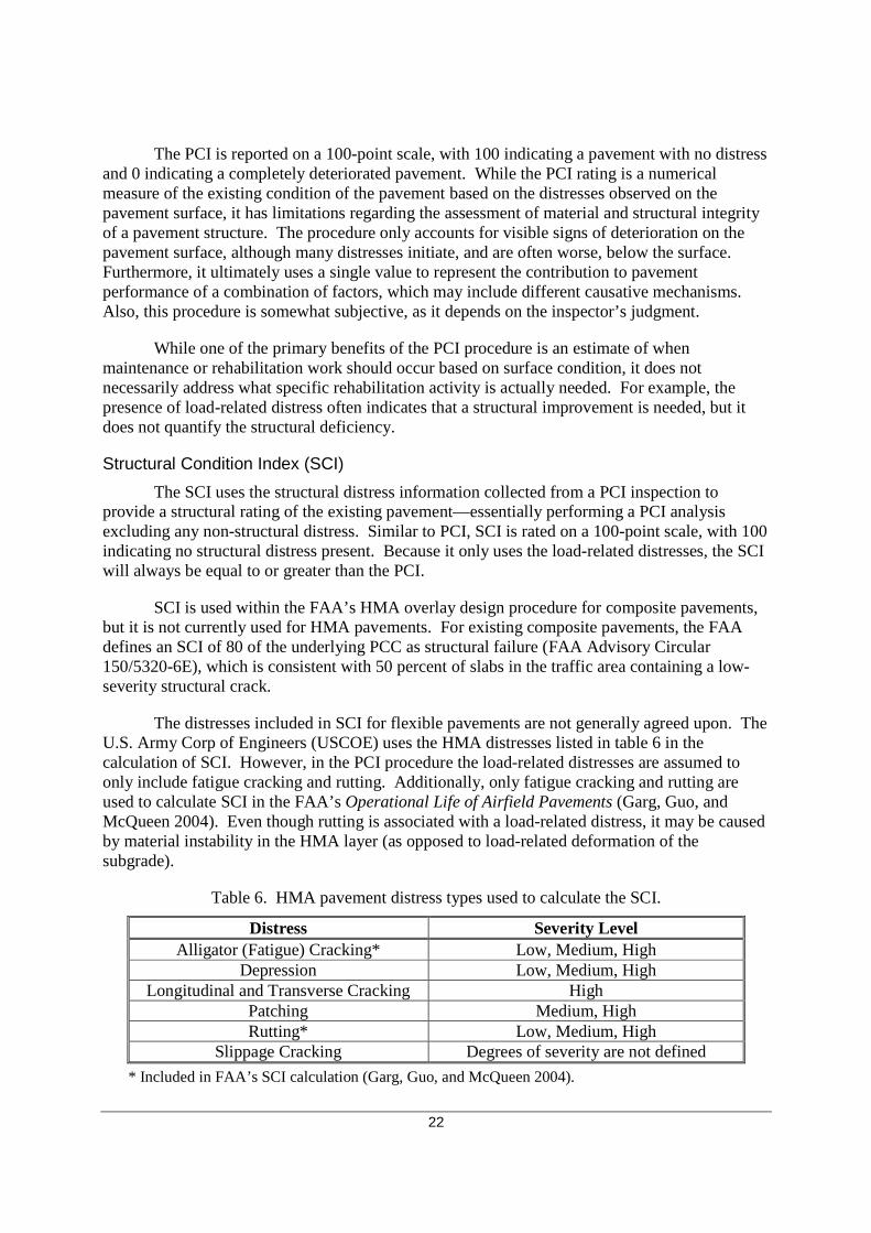
The distresses included in SCI for flexible pavements are not generally agreed upon. The U.S. Army Corp of Engineers (USCOE) uses the HMA distresses listed in table 6 in the calculation of SCI. However, in the PCI procedure the load-related distresses are assumed to only include fatigue cracking and rutting. Additionally, only fatigue cracking and rutting are used to calculate SCI in the FAA’s Operational Life of Airfield Pavements (Garg, Guo, and McQueen 2004). Even though rutting is associated with a load-related distress, it may be caused by material instability in the HMA layer (as opposed to load-related deformation of the subgrade).
Table 6. HMA pavement distress types used to calculate the SCI.
Distress Severity Level Alligator (Fatigue) Cracking* Low, Medium, High
Depression Low, Medium, High Longitudinal and Transverse Cracking High
Patching Medium, High Rutting* Low, Medium, High
Slippage Cracking Degrees of severity are not defined
* Included in FAA’s SCI calculation (Garg, Guo, and McQueen 2004).
23
Because SCI is based on the PCI procedure, it has some of its same advantages, such as systematically quantifying deterioration, monitoring deterioration and deterioration rates over time, and providing an indication of when rehabilitation is needed. However, it also means the SCI has some of the same limitations as the PCI procedure, including being a somewhat a subjective measure of condition that relies on the inspector’s judgment and only accounting for visible signs of damage on the surface of the pavement. Additionally, the SCI does not quantify other HMA performance factors due to construction or material issues, including but not limited to stripping or debonding between lifts.
DESTRUCTIVE TESTING METHODS
Destructive testing on existing airfield pavements typically includes coring or boring activities (or sample retrieval). While destructive testing methods can provide valuable information and are often needed to validate or calibrate non-destructive test results (discussed later), the biggest concern is typically the impact on airfield operations. Additionally, core data only provide a glimpse of the pavement structure at the specific location where the core is taken, and there is often a very limited number of cores retrieved from each project due to the time and expense associated with coring.
Pavement Coring and Boring
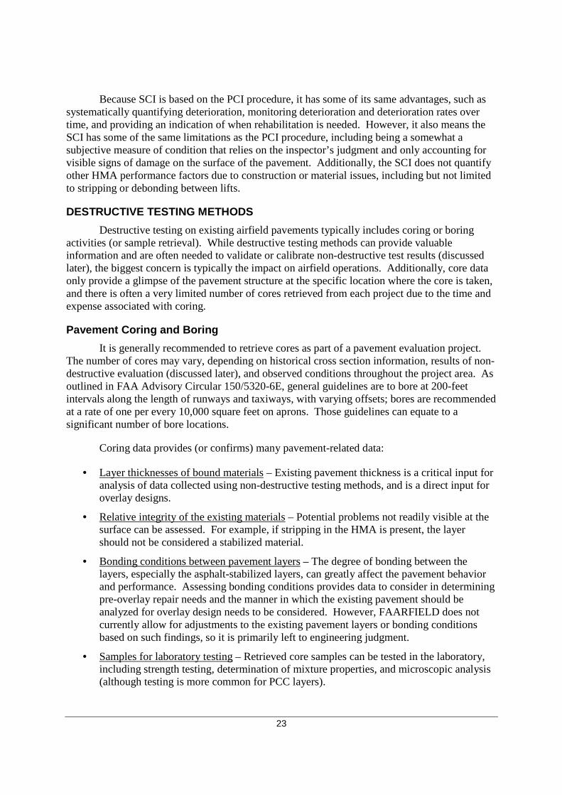
It is generally recommended to retrieve cores as part of a pavement evaluation project. The number of cores may vary, depending on historical cross section information, results of non-destructive evaluation (discussed later), and observed conditions throughout the project area. As outlined in FAA Advisory Circular 150/5320-6E, general guidelines are to bore at 200-feet intervals along the length of runways and taxiways, with varying offsets; bores are recommended at a rate of one per every 10,000 square feet on aprons. Those guidelines can equate to a significant number of bore locations.
Coring data provides (or confirms) many pavement-related data:
• Layer thicknesses of bound materials – Existing pavement thickness is a critical input for analysis of data collected using non-destructive testing methods, and is a direct input for overlay designs.
• Relative integrity of the existing materials – Potential problems not readily visible at the surface can be assessed. For example, if stripping in the HMA is present, the layer should not be considered a stabilized material.
• Bonding conditions between pavement layers – The degree of bonding between the layers, especially the asphalt-stabilized layers, can greatly affect the pavement behavior and performance. Assessing bonding conditions provides data to consider in determining pre-overlay repair needs and the manner in which the existing pavement should be analyzed for overlay design needs to be considered. However, FAARFIELD does not currently allow for adjustments to the existing pavement layers or bonding conditions based on such findings, so it is primarily left to engineering judgment.
• Samples for laboratory testing – Retrieved core samples can be tested in the laboratory, including strength testing, determination of mixture properties, and microscopic analysis (although testing is more common for PCC layers).
24
Sampling during boring provides additional information on unbound base, subbase, and subgrade thicknesses and material properties. Subgrade assessment, through in-place testing or sampling and laboratory testing, is commonly conducted to determine general subgrade classification and CBR values, the latter of which can be correlated to a modulus. Variations in subgrade conditions and areas with fill can also be identified. Chapter 2 of FAA AC 150/5320-6E provides additional discussion on soils investigation and associated testing.
Forensic Trenching
While not generally performed because of the significant disruption it causes to airfield traffic, conducting a trench excavation can also provide valuable information, such as the amount of rutting contributed by each pavement layer, and will allow for bulk sampling of materials.
Dynamic Cone Penetrometer (DCP) Testing
A DCP is a simple testing device consisting of a long steel rod with a steel cone (or point) attached to the end. A weight is dropped a given height to drive the cone into the ground. By measuring the penetration of the cone against the number of drops of the weight (the DCP Index), it is possible to plot resistance to penetration, which provides an indirect measure of the strength/compaction of the layer. The DCP Index can then be correlated to a CBR using manufacturer recommendations, Air Force Engineering Technical Letter 02-19: Airfield Pavement Evaluation Standards and Procedures (AFCESA 2002), or other references.
DCP testing can be used to supplement nondestructive testing data and is especially useful to test unbound material where cores have been removed. Not only can these data be used to determine layer stiffness, but changes in resistance can be used to distinguish unbound layer thicknesses. This test is less costly than taking bores and performing laboratory testing since it can be done quickly in the field with relatively inexpensive equipment. While the testing itself is relatively non-destructive, because of the need for coring to remove bound layers it is considered destructive. This test method does not work well when large aggregate (greater than approximately 2 inches) are present or when the CBR of the unbound material approaches 100.
Laboratory Testing
For airfield pavement evaluation projects, laboratory testing is most often performed on unbound materials collected from bores. These data are often analyzed for a subset of the retrieved materials for use in confirming field observations and field testing results (both destructive and non-destructive). One disadvantage is that destructive methods must be employed to retrieve the materials. Also, the cost of performing this testing typically limits the amount of data analyzed.
The FAA’s AC 150/5320-6E describes tests commonly performed on retrieved samples. CBR and resilient modulus testing are the most common laboratory subgrade tests performed as part of a geotechnical study, in addition to materials classification testing. FAARFIELD allows the input of either value, and assumes the resilient modulus is 1500 times the value of the subgrade CBR. One disadvantage of laboratory testing of subgrade material is that the results are for stress-state conditions during testing, and these are often not the same as those for the in-place material and pavement cross section.
When PCC cores are retrieved, it is not uncommon for splitting tensile strength testing or compressive strength testing to be completed (for correlation to flexural strength), or for select
25
cores to be analyzed for material problems (such as petrographic analysis to detect alkali-silica reactivity [ASR]). However, similar testing on HMA cores is less common. HMA material testing has been incorporated into design procedures for roadway evaluations (such as in AASHTO’s MEPDG), and there may be applications for these tests in airfield pavement evaluation and design. Although not part of FAA standards for evaluations, these laboratory tests (such as resilient modulus or dynamic modulus testing on retrieved HMA cores) may hold merit for airfield pavement evaluation to help establish or validate modulus values of the existing asphalt materials used in overlay design. The determined modulus for design based on laboratory testing currently needs to be a static value, and the reference rate of loading and temperature need to be considered in establishing this value. Although not considered in the current overlay design procedure, testing can also be performed to assess stripping potential, mixture stability, and other mixture properties.
NONDESTRUCTIVE TESTING METHODS
Falling weight deflectometer (FWD) testing is the most widely used NDT method, but other methods, such as ground penetrating radar (GPR) and seismic analysis, are also available. These methods are highly effective when used in concert, particularly on thick pavement structures. The use of GPR, as well as seismic methods, such as the Portable Seismic Pavement Analyzer (PSPA), has been found to be effective in cases of near-surface deterioration. The GPR is able to pick up the presence of moisture, and the PSPA is able to determine the moduli of surface layers and is relatively unaffected by the conditions/thickness of the bottom layers.
Falling Weight Deflectometer (FWD) Testing
FWD testing allows for a direct analysis of the structural integrity and load-carrying capacity of a pavement. Deflection testing data are used to backcalculate in situ material properties, to calculate pavement responses to load, and as inputs to other pavement analyses and designs. Deflection testing provides inputs for the structural analysis of the pavement sections without costly and time-consuming material testing required of destructive testing and analyses—however, limited destructive testing is beneficial to verify FWD results. Testing and analysis procedures and guidance for using the results are provided in the following publications:
• FAA Advisory Circular 150/5370-11A, Use of Nondestructive Testing in the Evaluation of Airport Pavements.
• UFC-3-260-03, Airfield Pavement Evaluation.
ASTM provides general guidelines for FWD testing in D 4694-96, Standard Test Method for Deflections with a Falling-Weight-Type Impulse Load Device (ASTM 2003a) and in D 4695-03, Standard Guide for General Pavement Deflection Measurements (ASTM 2003b). Other references can be found through the Federal Highway Administration (FHWA) and American Association of State Highway and Transportation Officials (AASHTO).
Deflection Analysis
Normalized deflections are used to analyze the load/deflection response of the pavement. The normalized deflection profile can be used to assess changes in subgrade support, variations within a pavement section (such as thickness), and the relative structural condition of a pavement. While deflections vary due to differences in pavement thickness or support, areas with comparatively high deflections or high standard deviations (typically coefficient of
26
variation greater than 25 percent) can indicate deterioration within the pavement structure, either globally or locally.
The differences in deflections help identify pavement sections for analysis. An example of a normalized deflection plot from a flexible pavement structure is presented in figure 9. There is one obvious pavement change at 2,000 feet and another, less distinct change near 7,000 feet. These observations were consistent with known cross section information for the facility. Another observation is that the outer test lanes (50 feet right and left of the centerline) generally have a different pavement response than those closer to the centerline. The different sections would be analyzed individually.
Figure 9. Example normalized deflection profile plot from a commercial airport.
Alternatively, Impulse Stiffness Modulus (ISM) can be plotted to provide the same general information as the normalized deflection data. ISM is defined as the applied load divided by the deflection at the center of the load plate. Cumulative difference (AASHTO 1993) is another method of evaluating defections to assess changes in load response. In the cumulative difference analysis, changes in the resulting slope indicate potential section changes.
In addition to normalized deflections, pavement layer moduli and subgrade support conditions can be analyzed from FWD data. Backcalculation is discussed in FAA Advisory Circular 150/5370-11A, as well as references from ASTM, AASHTO, FHWA, and others. The FAA also provides layered elastic backcalculation software (BAKFAA), but there are also other programs available.
Backcalculation of flexible pavement data is typically performed using layered elastic analysis, which solves for the layer moduli that result in the best fit between the field-measured deflection basin and the calculated deflection basin. The backcalculated subgrade support values represent a field value and are generally corrected to obtain a value consistent with laboratory testing results, which is the basis for most thickness design procedures. While the FAA does not recommend a specific correction factor, the AASHTO Mechanistic-Empirical Pavement Design Guide (NCHRP 2004) can be referenced for guidance.
The resulting subgrade modulus from backcalculation can be directly entered into FAARFIELD. The FAA uses the following relationship for correlation between subgrade modulus and CBR:
For a composite pavement (HMA overlay over PCC), rigid backcalculation procedures are used, and a subgrade k-value is determined rather than a resilient modulus. Rigid backcalculation procedures are typically based on plate-element analysis. The backcalculated k-value is a dynamic value, which is commonly multiplied by 0.5 to generate a static value for use in design. The k-values determined from FWD testing represent not only the natural subgrade, but also the strength of all underlying unbound (granular) pavement layers. This strength, once corrected to a static value for design use, is referred to as the top-of-base k-value. The k-value can be entered directly in FAARFIELD for design of an HMA overlay of a composite pavement. In such a case, the base layer should not be modeled (note: an undefined layer may need to be included under the PCC that has the same modulus as the subgrade depending on the cross section being analyzed). Correlation between k-value and subgrade modulus is performed using the relationship provided in FAA Advisory Circular 150/5370-11A, as shown below:
284.1)(26 kEsubgrade = (Eq. 3)
where:
Esubgrade = Backcalculated static subgrade elastic modulus, psi. k = Static modulus of subgrade reaction (k-value), psi/in.
This correlation can also be used for assessing flexible pavement designs from data obtained from PCC or composite pavements, such as when considering rubblization.
Pavement Layer Moduli
Pavement layer moduli are also obtained from backcalculation. Because HMA moduli are highly temperature dependent, values obtained during testing should be corrected to moduli at a standard temperature for thickness design. The Federal Highway Administration’s
28
Temperature Predictions and Adjustment Factors for Asphalt Pavement (FHWA 2000) provides guidance for making this conversion. The FAA design procedure assumes a standard temperature of 90 ºF, which is higher than that assumed for roadways.
The HMA modulus is also dependent on the rate of loading. The Unified Facilities Criteria (UFC 2001) recommends 10 hertz for runways and 2 hertz for taxiways and aprons. The AASHTO Mechanistic-Empirical Pavement Design Guide (NCHRP 2004) can be referenced for guidance on how frequency adjustments can be determined.
Values for HMA that are near the higher end of the expected range can represent oxidized or brittle pavements. While such layers may provide adequate structural support, they may be more susceptible to cracking and other environmental deterioration, which eventually weaken the overall structure. The standard deviations for the HMA moduli results generally are higher than the other layer calculations—coefficients of variation of 25 percent or greater for temperature corrected HMA moduli are not uncommon—although this variation is offset by the large number of data points for FWD testing. The following factors can affect the calculated results:
• Variation in pavement cross section, including layer thickness.
• Pavement deterioration.
• Varying support conditions.
• Errors in calculating any of the other layer moduli (i.e., the compensating layer effect).
• Variations in temperature-adjustment moduli, which is based on nationwide data.
Variations in pavement layer thickness have a significant impact on the results, which can cause moduli to be overestimated or underestimated. Therefore, accurate layer information is required for this testing and analysis method to be meaningful.
Additionally, an underlying assumption in the backcalculation analysis (layered elastic for flexible pavements and plate theory for composite pavements) is that test data are obtained from intact pavement areas without significant cracking between sensor locations. Therefore, the moduli results represent areas of pavement without substantial distress (and often pavements in need of rehabilitation have areas with deterioration). However, the normalized deflection plots can reveal weak areas, even if the test data from these areas cannot be further analyzed.
Ground Penetrating Radar (GPR)
GPR is a nondestructive testing method that uses electromagnetic pulses to map subsurface conditions. These pulses are transmitted from an antenna into the ground. When objects or interfaces with different dielectric constants are encountered, there are noticeable variations in the reflected signal, which is received by the device antenna. Elapsed time and dielectric properties are used to determine layer thicknesses. In this manner, changes in material types, debonding between pavement layers, voids, cracks, excessive moisture, and other abnormalities can often be detected. This testing method is acknowledged in FAA NDT documentation provided in Advisory Circular 150/5370-11A and additional documentation can be found in ASTM D6432-99(2005) Standard Guide for Using the Surface Ground Penetrating Radar Method for Subsurface Investigation.
29
GPR testing can be collected at highway speeds (or those of slow-moving aircraft), which reduces impact on airfield operations. This also allows for large areas to be tested in a limited amount of time.
The accuracy of the data depends on the emitted wave frequency; resolution is improved with higher frequencies, while penetration depth is increased with lower wave frequencies. Also, the accuracy of the results is typically greater near the pavement surface and diminishes with depth. Therefore, there is an accuracy tradeoff that may be required, especially for thick airfield pavements.
As with FWD testing, destructive tests such as coring are beneficial to calibrate and validate the results. While this does not replace the need for coring, it can reduce the number of cores required on a project. Due to its ability to collect continuous pavement thickness data, GPR works well when collected in conjunction with FWD testing, as pavement thickness is a critical input during backcalculation analysis using deflection data. The equipment can also be mounted on the same vehicles/equipment as used for FWD testing.
Seismic Testing
A potential option to assess the in-place concrete strength is seismic testing, which, like the FWD, is a nondestructive method. Seismic methods can be used to estimate slab thickness (via impact-echo testing) and the concrete dynamic modulus (via lab and field seismic testing). One device in particular, the portable seismic pavement analyzer (PSPA), was developed specifically for these applications and employs a combination of the equipment/instrumentation used for both impact-echo and ultrasonic testing (see figure 10). Like most seismic equipment, the PSPA is rapid and nondestructive, requires no specimen preparation, and can be easily performed at numerous locations throughout a project. Preliminary calibration and periodic validation of strength-modulus relationships are necessary. Although the PSPA is a relatively new device, it has shown great promise in measuring pavement strength. The FAA recently tested this device at their pavement test track in New Jersey (Garg and Hayhoe 2007).
Figure 10. Portable seismic pavement analyzer (left) and its sensor
unit (right) (Nazarian et al. 2006).
CORRECTIVE AND MITIGATIVE TECHNIQUES
The previous discussion focused on how to assess the existing pavement layer conditions. During rehabilitation design and construction, certain pavement distresses will need to be repaired to improve the general condition of the existing pavement. However, not all distresses
30
will be addressed prior to overlay. The current FAARFIELD overlay design procedure “assumes that the HMA overlay is to be placed on a base pavement with significant structural integrity” (FAA 2009). What constitutes “significant structural integrity” is not explicitly defined, but the procedure recommends that severely distressed areas and subsurface drainage conditions be carefully evaluated and corrective actions be taken to restore deficiencies prior to overlay application. Failure to do so, the procedure warns, will result in an unsatisfactory overlay due to the underlying deficiencies being reflected into the overlay (FAA 2009). There is little guidance as to the type, severity, and quantity of distress that should warrant repair.
As a minimum, the high-severity distresses and select medium-severity distresses, such as areas of alligator (fatigue) cracking or material instability, need to be repaired prior to overlay placement to ensure adequate performance. Without addressing severe distresses, an overlay cannot be expected to perform for an appreciable time. While pre-overlay repairs can address some level of distress, HMA overlays should not be considered if the results of an evaluation indicate the presence of any of the following conditions:
• Fatigue cracking is widespread and dictates full-depth pavement removal.
• HMA material deterioration, such as stripping, is widespread and dictates removal.
• Rutting is attributed to instability of the existing HMA, and the instability will result in the recurrence of rutting.
• Degradation or instability of the base/subbase material dictates removal and replacement.
Chapter 5 of Volume I, Assessment of FAA HMA Overlay Design Procedures, provides a detailed description of the various pre-overlay repair methods, many of which are also briefly discussed in FAA Advisory Circular 150/5320-6E. These actions can be considered in several broad categories:
Many pre-overlay repair activities are performed to address performance issues that are not part of the HMA overlay design procedure, such as reflective cracking, thermal cracking, and so on. Repairs that alter the condition of the existing pavement layers are primarily patching (replacement of deteriorated materials with new, sound materials) and surface recycling, which would entirely change the properties of the surface but is not commonly used on airfields. Milling of the pavement generally will remove the majority of surface deterioration (such as weathering/raveling) and needs to extend deep enough to address distresses such as slippage cracking and debonding between layers, if present.
Other repairs do not directly alter the condition of the existing pavement, but rather are performed to improve the overall overlay performance. These include interlayers, cushion layers, overlay reinforcement, and HMA overlay mixture modifications. These treatments alter the pavement response to loading, but are primarily intended to address mechanisms of distresses other than subgrade rutting and fatigue cracking.
Table 7 summarizes the targeted engineering/performance properties of the different techniques. As indicated in the table, most of the techniques address reflective cracking issues, which is not a FAARFIELD design criterion. Localized maintenance and repair techniques as well as other techniques that modify the existing pavement can also address fatigue cracking and/or permanent deformation issues, which are relevant design criteria in FAARFIELD (the latter typically being the controlling parameter). And, in addition to addressing reflective cracking issues, HMA overlay reinforcement techniques and mix modification techniques address fatigue and thermal cracking issues within the overlay.
Although the majority of pre-overlay treatments address reflective cracking, because reflective cracking is not a performance parameter currently evaluated in FAARFIELD, it is difficult to account for the purported performance benefits described earlier in this chapter for the various crack-mitigating techniques. These benefits primarily relate to the delay of reflective cracking (and probably fatigue cracking) development and not to the reduction in the development of permanent deformation, although some techniques (e.g., HMA overlay reinforcement and polymer-modified HMA) could influence this performance parameter.
32
Table 7. Engineering/performance properties targeted by corrective and mitigative techniques.
Corrective/Mitigative
Technique
Control of Reflective Cracking1
Improve Existing Pavement Structural
Integrity2
Increase HMA
Overlay Strength3
Increase HMA
Overlay Elasticity4
Localized Maintenance & Repair
Crack Sealing ���� ����5
Partial-/Full-Depth Repair ���� ����
Modify Existing Pavement
Cold Mill ���� ����
HIR Surface Recycle ���� ����
Surface Leveling Course ���� ����
Stress/Strain Relieving Interlayers
SAMI ����
ISAC ����
Strata ����
HMA Overlay Reinforcement
Steel Reinforcement ���� ����
Geotextile Fabrics ���� ����
Geogrids ���� ����
HMA Mix Modification
Rubber-Modified HMA ���� ����
Polymer-Modified HMA ���� ���� 1 Reduced tensile and/or shear strains at crack tip-overlay interface. 2 Reduced tensile and vertical strains in existing asphalt layers and vertical strain on subgrade. 3 Increased allowable strain (to reduce fatigue, thermal, and reflective cracking). 4 Increased recoverable strain (to reduce fatigue, thermal, and reflective cracking). 5 By waterproofing the overall pavement system.
Chapter 2 of Volume I of this study describes a process by which adjustments to the thickness and/or modulus of an existing cracked HMA pavement can be made to accommodate extra HMA overlay thickness required to reduce reflective cracking. The process is based on research performed by Sousa et al. (2005) and limited sensitivity analysis using FAARFIELD. It is premised on finite element analysis results indicating that reflective cracking development is driven in part by increased thickness and stiffness of the existing pavement, and that to counter the rate of crack development, a thicker HMA overlay is required. This process entails the following four steps:
1. Determine the thickness (tmeasured) and modulus of the existing cracked layer.
2. For every 145,000 psi above a modulus of 145,000 psi (referring to the existing layer modulus), reduce the thickness of the existing cracked layer by 2 inches (t1=tmeasured – 2). Use proportional values for other moduli.
3. For every 6 inches of thickness above 6 inches (referring to the existing layer thickness), reduce the thickness of the existing cracked layer determined in step 2 by 1 inch (tinput = t1 – 1). Use proportional values for other thicknesses.
33
4. Use the thickness determined in step 3 as the input thickness of the existing cracked layer in FAARFIELD.
Based on the review and discussion provided in Chapter 5 of Volume I, the suggested consideration of each corrective action is provided in table 8. Additionally, based on the sensitivity analyses conducted as part of this study and the FAA’s fatigue model currently incorporated into FAARFIELD, adjustment of the HMA overlay modulus is not recommended, even if the HMA material is designed specifically to improve pavement performance.
The reflective crack mitigation techniques summarized in table 8 have the ability to affect performance as if an additional overlay thickness had been placed, and thus slow the rate of crack development. In fact, geotextile fabrics were reported as being equivalent to between 1.2 and 2 inches of HMA and capable of providing between 2 and 3 years of additional HMA overlay life, under moderate circumstances (Von Quintus et al. 2009). The performance of other crack mitigation techniques were found to be similar or slightly less than that of geotextile fabrics (Von Quintus et al. 2009), and it would be reasonable to believe that “equivalent HMA thicknesses” could be applied to these techniques as well.
Table 9 provides suggested equivalencies for these techniques, based on the estimated overlay life extensions presented in Chapter 5 of the Volume I report. Depending on the results of a supplemental analysis of reflective cracking using the process outlined in Chapter 2 of Volume I, a crack mitigation technique could be selected using the equivalency values in this table, which could offset the required additional overlay thickness.
34
Table 8. Summary of corrective action design adjustments.
Category Corrective Action Proposed Adjustment
Localized Maintenance and Repair
Crack sealing Adjustment of existing modulus based on estimated condition after repair.
Partial-depth patching Adjustment of existing modulus based on estimated condition after repair
Full-depth patching Adjustment of existing modulus based on estimated condition after repair
Modification of Existing HMA Pavement
Cold milling
Milling depth should remove as much surface distress as possible; reduce existing pavement thickness in design accordingly; adjustment of existing modulus based on estimated condition after milling
Surface recycling Not commonly used; would modify existing layer modulus and potentially thickness
Surface leveling course Include with the determined overlay thickness
Stress/Strain Relieving Interlayers
Stress-absorbing membrane interlayer (SAMI)
Equivalent thickness in external reflective cracking check
Equivalent thickness in external reflective cracking check
HMA Overlay Reinforcement
Steel or wire fabric Equivalent thickness in external reflective cracking check
Geogrids Equivalent thickness in external reflective cracking check
Geosynthetic fabric Equivalent thickness in external reflective cracking check
Crack Arresting or Cushion Layers
Aggregate Not recommended
Asphalt-aggregate Model appropriate layer thickness and modulus
Bond Breakers Not recommended
HMA Overlay Mixture Modification
Rubber-modified asphalt binder
No adjustment
Polymer-modified asphalt binder
No adjustment
Soft (low-viscosity) asphalt binder
Not recommended
35
Table 9. Summary of estimated performance of crack mitigation techniques and corresponding equivalent HMA thicknesses.
Crack Mitigation Technique
Estimated HMA Overlay Life Extension, years
Estimated HMA Thickness Equivalency, in
SAMI 1 to 3 1.0 to 2.0 ISAC 1 to 2 (minimum) 1.0 to 1.5 (minimum) Strata 1 to 2 (minimum) 1.0 to 1.5 (minimum) Steel Reinforcement 1 to 2 (minimum) 1.0 to 1.5 (minimum) Geotextile Fabrics 2 to 3 1.5 to 2.0 Geogrids 1 to 3 1.0 to 2.0
SUMMARY
This chapter presents various pavement evaluation techniques to characterize the existing pavement layers. Traditional pavement evaluation techniques, including visual, destructive, and non-destructive techniques, are reviewed to assess the types of data collected.
While visual assessment data are only used on a limited basis, they can be used to assess whether data obtained through other evaluation techniques should be modified and to establish the need for corrective action or selection of a rehabilitation method other than HMA overlay. Non-destructive testing methods often allow a greater amount of data to be collected and analyzed, which can be an advantage over a destructive testing method such as coring. It is often beneficial to perform both destructive and non-destructive testing, as this offers the greatest coverage over a project area and offers a means to validate results. Table 10 provides a brief summary of the anticipated information obtained by traditional evaluation techniques and when each technique may be applicable.
Corrective and mitigative techniques and methods that can be used to repair existing distress and improve HMA overlay performance are also reviewed. The discussion includes a summary of the function or purpose and how the technique could be accounted for in the HMA overlay design process (see tables 8 and 9).
36
Table 10. Summary of applying traditional evaluation techniques.
Evaluation Technique Anticipated Design Information Suggested Use
PCI/SCI
• Assessment of condition (structural and functional) and cause(s) of deterioration.
• Adjustment of layer moduli based on global condition (before or after pre-overlay repairs).
Should be performed as part of all projects.
Coring and Boring
• Layer thicknesses and types. • General layer condition to assess
the need to adjust moduli.
Ideally performed as part of all projects, but especially for projects showing any structural or materials-related deterioration or when there is a significant change in the aircraft mix.
DCP
• Unbound layer moduli correlated to blow counts (or CBR).
Relatively inexpensive means of obtaining unbound layer strength properties. Consider when coring is already being performed and when FWD or PSPA testing will not be performed.
Laboratory Testing
• Unbound layer properties (type and CBR).
• PCC flexural strength correlated to core testing (compressive or splitting tensile strength).
• HMA testing less common but can provide layer moduli.
• Microscopic analysis of bound materials to assess materials-related deterioration.
Use in conjunction with coring and boring. Testing of unbound material properties is not as critical, unless stability is a concern. Bound material testing should be considered when structural- or material-related deterioration are present; can also provide correlation information for FWD and PSPA testing.
FWD
• Provide modulus for pavement layers and subgrade.
• Identify localized areas of weakness or poor support.
• Can sometimes detect delaminations in pavement structure.
Should be used when structural deterioration is apparent and when material properties of layers are not obtained through other means.
GPR
• Provides layer thicknesses. • Can sometimes detect
delaminations or voids in pavement structure.
Provides large coverage (compared to cores) and should be considered if significant thickness variations or delaminations are suspected. Can provide location-specific thickness data for FWD data analysis.
PSPA
• Provides surface layer modulus. • Can sometimes detect
delaminations in pavement structure.
Particularly useful in assessing surface layer variability, such as caused by structural or materials-related deterioration.
37
CHAPTER 4. DESIGN OF HMA OVERLAYS WITH FAARFIELD INTRODUCTION
It has previously been established that HMA overlay performance, and therefore HMA overlay design, is a function of many factors other than subgrade rutting and HMA (or PCC) fatigue. Additionally, it is widely recognized that the condition of the existing pavement structure, with or without pre-overlay repair, has a significant influence on the performance of an HMA overlay. As noted previously, this is not currently considered in the FAA’s HMA overlay design procedure. While the FAA discusses the evaluation of existing pavements in the HMA overlay design procedure, only marginal direction is provided on the use of the data collected. Similarly, while general guidelines are provided for the types of repairs that should be considered during rehabilitation, the design procedure does not account for any improvement in performance of the overlay (or reduced performance if corrective actions are not applied).
The FAA overlay design procedure, as well as the bulk of the discussion in this Guide is focused on the design of structural HMA overlays. That is, functional overlays are not directly considered, although it is recognized that many overlays are placed for reasons other than the need for a structural enhancement. A functional HMA overlay would be selected if:
1. The existing pavement is determined to be structurally adequate, either through a pavement evaluation program or historic performance with no structural distresses occurring and the design inputs (in particular the traffic) remain steady.
2. The condition of the surface prior to placing the HMA is intact and a good bond is achieved.
Because the existing pavement needs to be in good condition for a functional HMA overlay to perform as anticipated, many of the considerations in evaluating a pavement for the design of a structural HMA overlay can be applied to assessing a pavement for a functional overlay.
This chapter provides additional guidance for selecting design inputs for the HMA overlay design procedure using FAARFIELD.
DESIGN PARAMETERS FOR HMA OVERLAYS IN FAARFIELD
The flexible pavement design inputs in FAARFIELD include the following:
• Traffic data, including aircraft weights and volumes.
• Subgrade modulus.
• Aggregate subbase and/or base modulus.
• Existing HMA surface and base modulus.
• New HMA overlay modulus.
38
The following additional inputs for composite pavements are also required:
• Existing PCC modulus/flexural strength.
• SCI.
• CDFU.
These inputs are used within the FAARFIELD pavement models to design an HMA overlay thickness that satisfies the design criteria for subgrade rutting or HMA fatigue (or PCC cracking for composite pavements). A design life of 20 years is typically considered, but FAARFIELD does allow the design life to be adjusted (resulting in a non-standard design).
Traffic Inputs
FAARFIELD incorporates the use of the entire traffic mix in the FAA overlay design procedure. The damage to the pavement from each aircraft is analyzed and includes consideration of gear placement (offset from centerline) and wander. Traffic data (in particular the aircraft weight) can be the most influential input in design, as shown by the sensitivity analyses in Chapter 3 of the main report. Therefore, traffic data for a facility needs to be as accurate as possible.
Other factors need to be considered when developing the traffic projections, as discussed in section 304.d.4 of Advisory Circular 150/5320-6E. In particular, the determined pass-to-traffic cycle (P/TC) may change the aircraft departure volumes used in design. Facility use also needs to be considered. For example, a runway being used only for arrivals would not need to be designed using maximum take-off weights. There are many possible scenarios, and they cannot all be discussed here, but the designer needs to completely assess traffic requirements.
Each aircraft in the traffic mix is entered into FAARFIELD for design in the “Airplane” screen, as shown in figure 11. If an aircraft has significant operations but the specific (or similar) aircraft is not found in the FAARFIELD default libraries, an external library is available where new aircraft can be added.
39
Figure 11. FAARFIELD traffic data input.
Existing Pavement Layer Inputs
As discussed in Chapter 3, layer inputs should be determined by conducting a project-level evaluation. Design inputs required include subgrade support, individual pavement layer type, thickness, and modulus.
While historic documents can provide nominal pavement thicknesses, measurement of the in-place layers is ideal. This can be accomplished by coring, GPR, or some combination.
Layer moduli also need to be determined. Default values can be assumed, but determining the in-place properties provides a better indication of how the pavement has performed and will perform in the future. Samples obtained during coring and boring can be tested in the laboratory or layer moduli can be determined using NDT, as discussed in Chapter 3. FWD testing is a common NDT method employed to backcalculate pavement layer properties. Typical ranges and corresponding FAA default inputs are summarized in table 11.
Providing an adjustment to the layer inputs based on the overall pavement condition or improvement in condition due to anticipated pre-overlay repairs should also be considered. While the approach needs additional research, one possible adjustment scheme for the existing pavement modulus is using the anticipated (or effective) PCI at the time of overlay, as illustrated in figure 12. The proposed layer modulus adjustment is roughly based on the Asphalt Institute thickness equivalencies (AI 1987) and the PCI, but again additional research is needed to determine the appropriate magnitude of the reduction. This proposed adjustment assumes a modulus reduction based on the overall pavement condition. This is based on the
40
Table 11. Typical modulus values and ranges for paving materials.
Material
Backcalculation FAARFIELD Input2
Layer Type Typical Modulus
Range, psi1 Layer Type Modulus Range, psi Flexible surface HMA (dense-graded) surface 101,500 to 3,625,000 P-401 200,000 PCC surface PCC surface 1,450,000 to 10,150,000 P-501 4,000,000 Flexible stabilized bases
Asphalt treated base 101,500 to 3,625,000 P-401/P-403 Variable stabilized (flexible)
400,000 250,000 to 700,000
Rigid stabilized bases Econocrete base Cement treated base Soil Cement
507,500 to 5,075,000 290,000 to 2,900,000 145,000 to 1,015,000
P-306 P-304 P-301 Variable stabilized (rigid)
700,000 500,000 250,000
250,000 to 700,000
Unbound aggregate Granular (crushed) base Granular (uncrushed) subbase
14,500 to 217,500 7,250 to 108,750
P-209 P-154
75,0003
40,0003 Undefined N/A N/A Undefined 1,000 to 4,000,000
1 Stubstad et al. 2006 2 FAA 2009. 3 Initial values; final value used in design is a function of thickness and underlying layer modulus using the “Modulus” procedure.
41
backcalculation assumption that testing is performed at intact locations; therefore, the determined value is not entirely representative of the overall condition. For an existing pavement with an HMA surface and HMA base, engineering judgment should be used to determine whether or not an adjustment is made for both layers (i.e., are distresses primarily surface distresses or do they extend into the base). Pavements with a PCI less than 40 (or perhaps 50) are likely not candidates for an HMA overlay and are not illustrated on the adjustment chart.
Figure 12. Potential existing pavement modulus adjustment based on effective condition.
For example, an existing HMA pavement is inspected and found to have a PCI of 70.
With surface milling, localized patching, and crack sealing performed as pre-overlay repairs, the PCI is improved to 80 (effective PCI). FWD testing was also conducted as part of the evaluation and the existing HMA modulus was backcalculated and determined to be 480,000 psi (at 90 oF). To account for the overall condition after pre-overlay repairs characterized by the effective PCI, the modulus adjustment would be 0.9 using figure 12. Therefore, 432,000 psi would be used as the design modulus for the layer in FAARFILED.
Adjustment of the layer modulus is an approach that is not using the most influencial design input, as shown in the sensitivity analyses discussed in Volume I. An effective thickness could also be considered, but that approach would have a more significant impact on the design results should an error be made in selecting the input. Essentially, a reduction in the effective thickness of the existing HMA results in a nearly 1-to-1 reduction in the required HMA overlay thickness.
There are additional variables that need to be considered for composite pavements. The HMA overlay of an existing composite pavement introduces the need to characterize the underlying PCC layer and to account for the existing HMA overlay. In the FAA design procedure, the HMA overlay thickness is first determined as if the composite pavement were a bare PCC pavement “…and then adjust the calculated thickness to compensate for the existing overlay” (FAA 2009). In this case, a thickness, rather than modulus, adjustment needs to be considered. One possible method is to assume a 1-to-1 adjustment. Another possible method is
42
to assess an effective thickness of the existing HMA overlay. One estimate for an effective thickness (he) is based on Boussinesq’s equation, as follows:
3*
new
existingexistinge E
Ehh =
(Eq. 4)
Another approach is to use a weighted value, as follows:
new
existingexistinge E
Ehh *=
(Eq. 5)
where:
he = Effective thickness of existing HMA layer, in hexisting = Thickness of existing HMA layer, in Eexisting = Elastic modulus of existing HMA layer, psi Enew = Elastic modulus of new HMA layer, psi
The first approach (Eq. 4) will generally result in smaller adjustments to the thickness.
Characterizing the underlying PCC strength in composite pavements is critical due to its significant influence on the resulting overlay thickness, as shown in Chapter 3 of Volume I. Although the elastic modulus for a PCC layer cannot be altered in FAARFIELD, the flexural strength can be adjusted based on backcalculation or laboratory testing (such as splitting tensile strength testing of cores) results. PCC flexural strengths can range from 500 to 800 psi. If the flexural strength is below 500 psi, the best approach would be to model the PCC layer as a stiff base instead of an intact slab. Alternatively, such a weakened structure may be a better candidate for reconstruction.
The underlying PCC in a composite pavement is also characterized with SCI and CDFU. SCI ranges from 100 (no structural-related distress) to 67. An SCI of 80 is consistent with structural failure of the PCC pavement (50 percent of slabs cracked in wheel path). When SCI is 100, the CDFU is used to represent the damage that has been done before initiation of the first crack.
Sensitivities performed as part of this study show that SCI has a greater influence on design results than CDFU. It appears to be reasonable in the majority of cases to assume a CDFU of 100 percent and concentrate on establishing an appropriate SCI. However, because the overall condition of the underlying PCC is difficult to assess, establishing either of these inputs can be difficult. History and age of the pavement, condition of the existing HMA overlay related to underlying conditions (such as reflection cracking), and strength evaluation of the underlying PCC should all be considered in establishing SCI and CDFU. Because in most cases a PCC pavement is likely failed by the time an HMA overlay is placed, assuming an SCI of at least 80 and adjusting it accordingly based on currently available data is one approach to establishing a reasonable SCI. Without other data to consider, FAARFIELD documentation suggests SCI can be related to the historical Cb factor, as follows (FAA 2004):
43
25*100 −= bCSCI (Eq. 6)
The following steps should be considered in selecting design inputs for the design of HMA overlays using FAARFIELD:
• Use subgrade support values determined through project-level investigations.
• Use an “undefined” layer when the existing HMA modulus (such as determined by a NDT and/or laboratory testing) varies by more than 20 percent from the default layer modulus. The determined modulus can be used even if the difference is less than 20 percent, but the difference in design results will be negligible.
• Correlate underlying PCC flexural strength with results from NDT and/or laboratory testing.
• Review aggregate design moduli to determine suitability of using the default layer types; evaluate changing layer type if moduli are greater than 20 percent different than those determined through evaluation.
• Consider overall pavement condition and any anticipated improvement in pavement condition in selecting layer inputs.
• Assess the effective thickness of the existing HMA overlay in composite pavements.
• Assuming a CDFU of 100 percent and establishing an appropriate SCI is likely a reasonable approach for composite pavements.
• Consider external design checks for reflection cracking (such as discussed in Volume I).
• Consider laboratory evaluation of materials if there are historical problems with performance (such as in-layer rutting).
New HMA Overlay Input
The available inputs for a new HMA overlay layer are limited. The default layer modulus is 200,000 psi and is assumed to be at 90 oF. Alternatively, an “undefined” layer may be used. However, the use of an “undefined” layer has its limitations, particularly when the existing surface layer also varies from the default layer properties.
An aspect not directly taken into account in the FAA’s design procedure is the temperature dependency of HMA materials. This is especially relevant to the surface layer. The default HMA overlay modulus is 200,000 psi based on a design temperature of 90 oF. The analyses conducted as part of this study (Chapter 3 of Volume I) suggest that HMA fatigue can become a significant factor when the overlay modulus exceeds around 300,000 psi, a value that could easily be exceeded in most climatic regions. However, there is an opposite effect for varying the existing HMA and overlay layer moduli: increases in the HMA overlay modulus results in an increase in damage, but increases in the existing pavement modulus results in a decrease in damage (see Chapter 6 of Volume I for additional detail). For both cases, the HMA CDF is controlled by the existing pavement layer. Therefore, with the current version of FAARFIELD, the new HMA overlay should be set as the default layer type for most cases, unless there are clear reasons to consider adjusting it.
44
HMA OVERLAY DESIGN EXAMPLES
Existing HMA Pavement
As a design example, assume that a project-level assessment is conducted on an existing flexible pavement at a commercial airport. The traffic data summarized in table 12 is used in this example. The cross section determined by evaluation is summarized in table 13.
Table 12. Summary of commercial airport traffic mix used in sensitivity analysis.
Aircraft Model Gear
Configuration Weight, lbs
Average Annual
Departures A300-B4 std 2D 365,747 900 A319-100 opt D 150,796 6,023 A320-200 Twin std D 162,922 9,379 A321-100 std D 183,866 2,713 A340-300 std 2D/D1 608,245 359 A380-800 2D/3D2 1,239,000 266 B717-200 HGW D 122,000 3,038 Adv. B727-200 Option D 210,000 265 B737-500 D 134,000 4,615 B737-700 D 155,000 32,823 B747-400B Combi 2D/2D2 877,000 1,510 B757-200 2D 256,000 20,312 B767-300 ER 2D 413,000 7,997 B777-300 ER 3D 777,000 1,664 DC10-30/40 2D/D1 583,000 1 DC9-51 D 122,000 9 L-1011 2D 498,000 4 MD11ER 2D/D1 633,000 609 MD83 D 161,000 361 RegionalJet-700 D 72,500 8,928 RegionalJet-200 D 47,450 2,193 Dual Whl-30 D 35,600 4,778 Dual Whl-20 D 16,300 800 Single Wheel-10 S 6,536 371 Single Wheel-15 S 14,550 1,470 Single Wheel-12.5 S 12,000 1,417 Single Wheel-5 S 5,100 1,932 Single Wheel-5 S 3,800 3,453
Table 13. Summary of flexible pavement cross sections.
Layer Property Value HMA Surface, in 4.0 HMA Base, in 4.0 Aggregate Subbase (P-209), in 12.0
45
Deflection testing is also performed on the pavement with layer properties determined by backcalculation as summarized in table 14. While the layer moduli vary throughout the year from temperature and moisture fluctuations, a representative value is suggested for use until such a time as FAARFIELD incorporates an automated process to account for seasonal effects (such as that in the military’s PCASE design software). This assumes that load applications are approximately equal during each season; if that is not the case, additional modeling may be required.
Table 14. Summary of example pavement layer properties.
The project-level PCI of the section is determined to be 68. The pre-overlay repairs, consisting of crack sealing and patching, are anticipated to raise the PCI to 75 prior to construction of an HMA overlay. Using the adjustment scheme presented in figure 12 to account for the overall pavement condition, a factor of 0.85 is applied to the determined HMA modulus, resulting in an existing HMA surface modulus of 297,500 psi. For this example, it is assumed the majority of distresses are contained in the surface layer; therefore, the base layer modulus is not adjusted. The new HMA overlay is assumed to have a layer modulus of 200,000 psi.
To analyze HMA fatigue for this design, the HMA fatigue calculations are turned on in the FAARFIELD “Options” screen by unchecking the “No HMA CDF” selection box, shown in figure 13.
Once the project file and overlay structure are established, the existing cross section data, including the layer types, thicknesses, and subgrade modulus, are entered in the structure screen, shown in figure 14,
Figure 14 illustrates the use of the default P-401/P-403 HMA surface for the existing HMA surface, which has a fixed layer modulus of 200,000 psi. To account for the layer modulus determined through evaluation, an “undefined” layer can be used for the existing surface layer, as shown in figures 15 and 16 for the backcalculated modulus and proposed effective modulus, respectively.
The HMA overlay requirement is then determined in FAARFIELD and summarized in figures 17, 18, and 19 for the three modulus scenarios.
46
Figure 13. Selection of running HMA fatigue check in FAARFIELD.
Figure 15. Using “undefined” layer to input backcalculated surface layer modulus.
Figure 16. Using “undefined” layer to input effective surface layer modulus.
48
Figure 17. HMA overlay results using default HMA surface layer.
Figure 18. HMA overlay results using backcalculated HMA surface layer.
49
Figure 19. HMA overlay results using effective HMA surface layer.
The default HMA surface modulus results in the greatest HMA overlay requirement (7.15 inches), while the unadjusted backcalculated modulus has the lowest HMA overlay requirement (6.36 inches). The analyses suggest that an HMA overlay of 6.5 inches will likely perform satisfactorily.
As discussed previously, FAARFIELD does not consider failure mechanisms other than rutting and fatigue. While many assessment methods for other distresses, including reflection cracking, have not been widely used or validated, methods of performing design checks are discussed in Volume I and could be considered. Accounting for some of the possible mitigation techniques (such as interlayers) can be accounted for in these checks.
Existing Composite Pavement
An existing composite pavement cross section is also analyzed for the same commercial facility as an example. The composite pavement cross section determined from a project-level evaluation is summarized in table 15.
50
Table 15. Summary of composite pavement cross section and properties.
Layer Property Design Value Existing HMA Overlay, in 3.01 PCC Pavement, in 18.0 PCC Flexural Strength, psi 650 HMA Base, in 6.0 Aggregate Subbase (P-209), in 6.0 Subgrade Modulus, psi 17,200 1 Existing HMA overlay is not modeled in FAARFIELD but is
subtracted from the calculated HMA overlay thickness for bare PCC.
Based on historical records of distresses in the PCC prior to initial overlay and distresses observed in the existing HMA overlay, the CDFU and SCI are estimated to be 100 percent and 83, respectively. The composite pavement inputs are illustrated in the FAARFIELD screen shown in figure 20.
Figure 20. Existing composite pavement layer inputs in FAARFIELD.
51
The results from FAARFIELD using the determined inputs are summarized in figure 21, with a 13.64-inch HMA overlay being required. If the default PCC flexural strength (700 psi) is used, an overlay thickness of 9.92 inches is required, as shown in figure 22. By not evaluating the in-place PCC strength and using the default strength, the HMA overlay thickness can be significantly under-designed (or over-designed if the PCC flexural strength is greater than the default value).
Figure 21. HMA overlay results using determined PCC flexural strength.
52
Figure 22. HMA overlay results using default PCC flexural strength.
The presence of the existing HMA overlay needs to be accounted for in the design results. A straight subtraction of the existing thickness results in an HMA overlay requirement of 10.64 inches. Assuming the existing HMA overlay has an effective modulus of 297,500 psi, as used in the flexible design example, an effective thickness of 3.4 inches (using Eq. 4) could be used based on the slightly higher modulus. A 10.24-inch HMA overlay is then determined.
SUMMARY
This chapter provides a summary of developing inputs (including adjustment for overall pavement condition and anticipated improvement from pre-overlay repairs) for use in FAARFIELD for the design of HMA overlays. Design examples are provided for flexible and composite pavements with discussion on the differences in results using specific default program values. In general, the designer should consider the following:
• Obtain as accurate of traffic data as possible, as the pavement design thickness is extremely sensitive to aircraft weight.
• Use the default modulus for the HMA overlay.
• Use one or more pavement evaluation techniques to determine existing layer moduli. Assess the impact of other data collected during evaluation (such as layer condition, bonding, and so on).
• Consider adjustment of NDT-determined layer moduli for overall condition and effects of repairs (or not performing repairs).
53
• Use determined modulus for the existing HMA layer(s) if greater than approximately a 20-percent difference from the default values.
• For composite pavement: – Determine flexural strength from evaluation. – Assess the effective thickness of existing HMA overlay in composite pavements. – Assuming a CDFU of 100 percent and establishing an appropriate SCI is likely a
reasonable approach for composite pavements.
• Use representative layer moduli unless there is a significant difference in loadings during different seasonal periods.
• Perform external design checks for reflective cracking.
• Consider assessment of in-layer rutting of HMA if loading conditions are unique or if there is a history of HMA-material rutting with local materials.
54
55
5. REFERENCES
Air Force Civil Engineer Support Agency (AFCESA). 2002. Airfield Pavement Evaluation Standards and Procedures. Engineering Technical Letter. (ETL) 02-19. Tyndall Air Force Base, FL. American Association of State Highway and Transportation Officials (AASHTO). 1993. Guide for Design of Pavement Structures. AASHTO, Washington, DC. American Society for Testing and Materials (ASTM). 2010. ASTM D-5340-10, “Standard Test Method for Airport Pavement Condition Index Surveys.” Annual Book of ASTM Standards, Section Four: Construction, Volume 4.03: Road and Paving Materials; Vehicle-Pavement Systems. ASTM, West Conshocken, PA. ASTM. 2005. ASTM D6432-99(2005). Standard Guide for Using the Surface Ground Penetrating Radar Method for Subsurface Investigation. ASTM, West Conshocken, PA. ASTM. 2003a. Standard Test Method for Deflections with a Falling-Weight-Type Impulse Load Device. ASTM D4694-96. ASTM, West Conshocken, PA. ASTM. 2003b. Standard Guide for General Pavement Deflection Measurements. ASTM D4695-03. ASTM, West Conshocken, PA. Federal Aviation Administration (FAA). 2009. Airport Pavement Design and Evaluation. Advisory Circular 150/5320-6E. U.S. Department of Transportation, FAA, Washington, DC. FAA. 2007. Guidelines and Procedures for Maintenance of Airport Pavements. Advisory Circular 150/5380-6B. U.S. Department of Transportation, FAA, Washington, DC. FAA. 2004. Use of Nondestructive Testing in the Evaluation of Airport Pavements. Advisory Circular 150/5370-11A. U.S. Department of Transportation, FAA, Washington, DC. FAA. 1995a. Airport Pavement Design and Evaluation. Advisory Circular 150/5320-6D. U.S. Department of Transportation, FAA, Washington, DC. FAA. 1995b. Airport Pavement Design for the Boeing 777 Airplane. Advisory Circular 150/5320-16. U.S. Department of Transportation, FAA, Washington, DC. Garg. N. and Hayhoe, G.F. 2007. “Characterization of Rubblized Concrete Airport Pavements at the NAPTF using Non-Destructive Testing Methods.” Proceedings of the 2007 FAA Worldwide Airport Technology Transfer Conference. FAA, Atlantic City, NJ. Garg, N., E. Guo, and R. McQueen. 2004. Operational Life of Airport Pavements. DOT/FAA/AR-04/46. U.S. Department of Transportation, FAA, Washington, DC. Kim, T. and E. Tutumluer. 2006. “Field Validation of Airport Pavement Granular Layer Rutting Predictions.” Transportation Research Record 1952. Transportation Research Board, Washington, DC.
56
Lukanen, E., R. Stubstad, and R. Briggs. 2000. Temperature Predictions and Adjustment Factors for Asphalt Pavement. FHWA-RD-98-085. Federal Highway Administration, Washington, DC. Majidzadeh, K., A. Abdulshafi, G. J. Ilves, and A. McLaughlin. 1987. “A Mechanistic Model for Thermally Induced Reflection Cracking of Portland Cement Concrete Pavement with Reinforced Asphalt Concrete Overlay.” Transportation Research Record 1117. Transportation Research Board, Washington, DC. National Cooperative Highway Research Program (NCHRP). 2004. Guide for Mechanistic-Empirical Design of New and Rehabilitated Pavement Structures, Parts 1-4. Transportation Research Board, Washington, DC. Nazarian, S., D. Yuan, K. Smith, F. Ansari, and C. Gonzalez. 2006. Acceptance Criteria of Airfield Concrete Pavement Using Seismic and Maturity Concepts. IPRF-01-G-002-02-2. Innovative Pavement Research Foundation (IPRF) Programs Management Office, Skokie, IL. Seeds, S. B., B. McCullough, and R. Carmichael. 1985. “Asphalt Concrete Overlay Design Procedure for Portland Cement Concrete Pavements.” Transportation Research Record 1007. Transportation Research Board, Washington, DC. Smith, R. E., R. Palmieri, M. I. Darter, and R. Lytton. 1984. Pavement Overlay Design Procedures and Assumptions, Volume II—Guide for Designing an Overlay. FHWA/RD-85/007. Federal Highway Administration, Washington, DC. Sousa, J. B., J. C. Pais., R. Saim, G. B.Way, and R. N. Stubstad. 2005. “Development of a Mechanistic-Empirical Based Overlay Design Method for Reflective Cracking.” Road Materials and Pavement Design. Volume.6, Number 3. France. U.S. Army Corps of Engineers Engineering Research and Development Center. 2005. Pavement-Transportation Computer Assisted Structural Engineering (PCASE) User Manual. U.S. Army Corps of Engineers, Vicksburg, MS. U.S. Army Corps of Engineers Research and Development Center. 2001. Pavement Design for Airfields. Unified Facilities Criteria (UFC) 3-260-02. U.S. Army Corps of Engineers, Vicksburg, MS. U.S. Army Corps of Engineers Research and Development Center. 2001. Airfield Pavement Evaluation. Unified Facilities Criteria (UFC) 3-260-03. U.S. Army Corps of Engineers, Vicksburg, MS. U.S. Army Corps of Engineers Research and Development Center. 2001. O&M: PAVER Concrete Surfaced Airfields Pavement Condition Index (PCI). Unified Facilities Criteria (UFC) 3-270-05. U.S. Army Corps of Engineers, Vicksburg, MS. U.S. Army Corps of Engineers Research and Development Center. 2001. O&M: PAVER Asphalt Surfaced Airfields Pavement Condition Index (PCI). Unified Facilities Criteria (UFC) 3-270-06. U.S. Army Corps of Engineers, Vicksburg, MS.
57
Von Quintus, H. L., J. Mallela, W. Weiss, S. Shen, and R. L. Lytton. 2009a. Techniques for Mitigation of Reflective Cracks. AAPTP 05-04 Final Report. Airfield Asphalt Pavement Technology Program (AAPTP), Auburn University, AL. Von Quintus, H., J. Mallela, W. Weiss, and S. Shen. 2009b. Techniques for Mitigation of Reflective Cracking. AAPTP 05-04 Technical Guide. Airfield Asphalt Pavement Technology Program (AAPTP), Auburn University, AL.