Page 1
Industrial Robot, Vol. 39, No. 1, pp. 57–68, 2012.
1
Assessment of the Positioning Performance of an Industrial Robot
Mohamed Slamani, Albert Nubiola, Ilian A. Bonev
École de technologie supérieure, Montreal (Quebec), Canada
Abstract
Purpose – The purpose of this work is to investigate the use of a laser tracker, a laser interferometer sys-
tem and a telescopic ballbar for assessing the positioning performance of a six-axis industrial serial robot.
The paper also aims to illustrate the limitations of these three metrology instruments for the assessment of
robot positioning performance and to demonstrate the inadequacy of simplistic performance tests.
Design/methodology/approach – Specific test methods in the case of the laser interferometer system and
the telescopic ballbar are proposed. Measurements are analyzed in accordance to the ISO 9283 norm.
Findings – It is found that, in static conditions and after a relatively short warm-up, the unidirectional
position repeatability of the non-calibrated industrial robot under study (an ABB IRB 1600) is better than
37 μm, the unidirectional orientation repeatability is at worst 87 μrad, the linear position accuracy is bet-
ter than 650 μm, and the rotation accuracy is at worst 2.8 mrad (mainly because of the sixth robot axis). It
was also found that the dynamic (radial) errors due to vibrations can be up to approximately ±250 µm
along a small circular path at TCP speed of 700 mm/s.
Practical implications – It is pointed out that the use of a laser tracker (or any other large range portable
3D measurement system) is questionable for assessing—let alone analyzing in depth—the unidirectional
position repeatability of some of today’s industrial robots. It is also demonstrated that the laser interfer-
ometer system can be used for measuring linear errors along a linear path of motion as well as angular
errors about axes orthogonal to the path of motion. Finally, it is shown that the telescopic ballbar is an
excellent, comparably low-cost, high-precision tool for assessing the static and dynamic positioning per-
formance of industrial robots and its use in robotics should be further developed.
Originality/value – This work is the first to detail the use of three metrology equipments for assessing
the positioning performance of an industrial robot. Experimental results are presented and discussed.
Some guidelines for optimizing the positioning performance of an industrial robot are provided.
Keywords repeatability, absolute accuracy, laser tracker, laser interferometer, telescoping ballbar.
Paper type Research paper
Introduction
These days, two measures are commonly used for describing the positioning performance of in-
dustrial robots—repeatability and accuracy—and the international norm specifying how these
and many other performance criteria should be evaluated is ISO 9283 (1998).
Loosely speaking, pose repeatability is the ability of the robot to return repeatedly to the
same pose (i.e., position and orientation of the end-effector). In robotics, repeatability, as defined
in ISO 9283 and used by all industrial robot manufacturers, actually refers to unidirectional re-
peatability only, i.e., the ability to return to the same pose from the same direction, thus minimiz-
ing the effects of backlash. Multidirectional repeatability can be twice the unidirectional repeata-
bility or even worse.
On virtually all six-axis serial industrial robots, encoders with typical resolution of 0.01°
are placed on the shafts of the motors, and gear reduction ratios of at least 100 are generally used
for the main axes. It is therefore evident that the unidirectional repeatability of these robots is
primarily affected by lost motion (hysteresis, backlash, and torsional elasticity) and friction in the
gear trains, and only slightly influenced by the limited encoder resolution. Indeed, a resolution of
0.0001° (0.01°/100) on one of the main robot axes translates to a worst TCP (tool center-point)
Page 2
Industrial Robot, Vol. 39, No. 1, pp. 57–68, 2012.
2
resolution of less than 3 μm on a medium size industrial robot. Repeatability is also considerably
affected by thermal expansion, but only when long periods of time are considered (e.g., several
hours of operation after cold start).
Repeatability is therefore improved by either using direct-drive motors (as in some
SCARA robots), high-precision gear trains (as in most Stäubli robots) or by placing high-
resolution encoders at the output of the gear trains. All of these solutions, however, raise consid-
erably the manufacturing cost of an industrial robot.
Loosely speaking, (volumetric) accuracy is the ability of the robot to attain a command
pose with respect to its base reference frame. Since identifying this reference frame is not always
simple, accuracy is most typically tested in relative measurements, e.g., the distance accuracy is
the ability of the robot to displace its TCP a prescribed distance.
Accuracy is obviously affected by the same factors as multidirectional repeatability but it is
influenced mostly by geometric inaccuracies and elasticity, present in both the links and the
transmissions. Fortunately, these two types of errors can be modeled to some extent in a process
known as robot calibration (Abderrahim et al., 2006).
The demand for industrial robots having better repeatability and higher volumetric accura-
cy has been constantly growing in the past decade, especially in the aerospace sector (Summers,
2005). Today, most industrial robot manufacturers and a few service providers (such as Dynalog
of USA) offer robot calibration services. Furthermore, most industrial manufacturers now adopt
the ISO 9283 norm, which was not the case a decade ago (Greenway, 2000; Schröer 1999). Nev-
ertheless, the only upfront information regarding the positioning performance of an industrial
robot continues to be a single measure specified as something like “position repeatability accord-
ing to ISO 9283”, which actually refers to the average unidirectional position repeatability at five
poses obtained from thirty cycles and typically measured using a laser tracker. A few additional
performance measures might sometimes be obtained from the robot manufacturer (e.g., found in
the product manual of the robot), such as linear path repeatability and linear path accuracy, but
even this information is highly insufficient and impossible to use for comparison purposes. In-
formation about the volumetric accuracy is even more difficult to obtain and validate, unless the
robot is calibrated.
Assessing the positioning performance of an industrial robot is a very complex task that
requires expensive metrology equipment. In 1995, the ISO published a guide on test equipment
and metrology methods for robot performance evaluation in accordance to ISO 9283 (ISO TR
13309, 1995). While various tests can be performed with low-cost tooling such as digital indica-
tors (comparators) and reference objects, the most common equipment used for robot calibration
and accuracy assessment remains the laser tracker. Indeed, a laser tracker is relatively simple to
use and can quasi-continuously (typically every millisecond) measure the position of a single
SMR (spherically-mounted reflector) or even measure the complete pose in static mode (by
measuring the positions of three SMRs, however, using the so-called ADM mode, which is less
accurate), in the entire workspace of an industrial robot. Unfortunately, laser trackers are exces-
sively expensive ($100K and more) and very sensitive to air turbulences. Furthermore, their vol-
umetric accuracy and repeatability is much worse than that of two high-precision single-axis
measurement instruments commonly used for machine tool calibration: the laser interferometer
system and the telescoping bar (also called double-ball bar, or DBB). These are, however, not
described in the ISO guide and are rarely used in conjunction with industrial serial robots.
In this paper, we analyze the positioning performance of a non-calibrated ABB IRB1600
industrial serial robot using a FARO ION laser tracker (ADM only), a Renishaw XL80 laser in-
terferometer system and a Renishaw QC20-W telescoping ballbar. The laser tracker is used only
Page 3
Industrial Robot, Vol. 39, No. 1, pp. 57–68, 2012.
3
to measure the unidirectional position repeatability as per the ISO 9283 inclined plane test, while
the two other measurement instruments are used in a much more comprehensive manner.
Accuracy Assessment of Industrial Robots
Young and Pickin (2000) assessed the static positioning accuracy and static positioning repeata-
bility of three large six-axis industrial serial robots by measuring only the linear position error
and the two straightness errors at five poses along a linear path parallel to the base X axis and at
five poses along a linear path parallel to the base Y axis using a Renishaw laser interferometer
system. The authors found that the bidirectional position repeatability of each robot is within
200 μm, while the linear position errors can be as large as 1.6 mm. However, as we will discuss
in this paper, measuring straightness errors (which is different from path accuracy) in an indus-
trial robot is of no practical interest.
More recently, Airbus UK (Summers, 2005) conducted a comprehensive performance as-
sessment of four different six-axis calibrated industrial serial robots using the Krypton motion
tracker (currently manufactured by Nikon Metrology) that has a specified volumetric accuracy of
approximately 100 μm (within a three-meter range). While the volumetric accuracy errors of
these calibrated robots were as large as 7 mm at one meter, repeatability was found to be only 20
to 30 μm.
Bréthé et al. (2006) used a triad of digital indicators, each having accuracy of 3 μm, to
measure and model the position repeatability of an old KUKA IR364 industrial robot at several
locations and found it to be less than 36 μm.
In her Ph.D. thesis, Eastwood (2004), and in related publications such as (Eastwood and
Webb, 2009), a triad of digital indicators was used to evaluate the impact of various sources of
errors in a Tricept parallel robot, and propose compensation strategies for some of these errors.
This work is very comprehensive in analyzing the various sources of errors, but little attention is
paid to the choice of measurement equipment and to the different performance criteria that can
be used to represent the positioning performance of a robot.
Muelaner et al. (2010) used a FARO laser tracker to assess the repeatability of a large
KUKA KR240 industrial serial robot and found that it is no more than 10 μm, when short periods
of time are considered. The validity of such results is, however, questionable since the repeatabil-
ity of the FARO laser tracker (ADM only) itself is approximately 8 μm at two meters. Further-
more, the TCP speed used in the repeatability measurements was not specified.
While the telescopic ballbar nowadays is a standard tool for accuracy assessment and cali-
bration of (the XYZ part) of CMMs and machine tools and is very popular for the calibration of
parallel robots (Ota et. al., 2000), its use in industrial serial robots, though proposed more than
two decades ago (Vira and Lau, 1987), remains very limited (for example, Karlsson and
Brogårdh, 2001, used it but in combination of an inclinometer). Indeed, the software that comes
with the popular telescopic bar manufactured by Renishaw is specifically developed for use on a
machine in which the circular motion is generated by the simultaneous movement of two orthog-
onal linear axes, and a defined test sequence should be followed. The use of the telescopic
ballbar in five-axis machine tools, when several axes are driven simultaneously or when rotary
axes are driven, is still a research topic (Lei et al., 2009).
Test Methods
Tests were performed on an ABB IRB 1600-6/1.45 industrial robot installed in a laboratory facil-
ity with a relatively constant ambient temperature of 21°C (Fig. 1). The door of the laboratory
Page 4
Industrial Robot, Vol. 39, No. 1, pp. 57–68, 2012.
4
remained closed during each test to reduce environmental fluctuations to a minimum. The robot
was manufactured in 2008 and has never been in a collision accident. It does not have the Abso-
lute Accuracy option (i.e., it is not calibrated) nor the Advanced Shape Tuning option (for com-
pensating the effects of friction at low speeds). A multi-purpose end-effector (well visible in
Figs. 2 and 4) was used to which up to eight SMRs can be securely mounted, in addition to the
optics of the laser interferometer system and the tool cup of the telescoping ballbar.
Steel discs can also be attached to the end-effector to increase its weight. However, despite
the fact that ISO 9283 prescribes that performance tests should be made at maximum payload,
for simplicity, we decided to not change the weight of the end-effector. Indeed, preliminary tests
showed that there is virtually no change in the robot repeatability when increasing the weight of
the end-effector from about 3 kg to 6 kg (the maximum payload for our robot). There is also very
slight change in the accuracy of the robot as assessed in the tests described in this paper. Howev-
er, note that the TCP droop at maximum reach and maximum payload is as much as 0.3 mm.
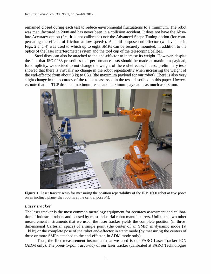
Figure 1. Laser tracker setup for measuring the position repeatability of the IRB 1600 robot at five poses
on an inclined plane (the robot is at the central pose P1).
Laser tracker
The laser tracker is the most common metrology equipment for accuracy assessment and calibra-
tion of industrial robots and is used by most industrial robot manufacturers. Unlike the two other
measurement instruments that we used, the laser tracker yields the complete position (in three-
dimensional Cartesian space) of a single point (the center of an SMR) in dynamic mode (at
1 kHz) or the complete pose of the robot end-effector in static mode (by measuring the centers of
three or more SMRs attached to the end-effector, in ADM mode only).
Thus, the first measurement instrument that we used is our FARO Laser Tracker ION
(ADM only). The point-to-point accuracy of our laser tracker (calibrated at FARO Technologies
Page 5
Industrial Robot, Vol. 39, No. 1, pp. 57–68, 2012.
5
headquarters just before our tests) is specified as 22 µm at 2 m (i.e., half the so-called maximum
permissible error , or MPE, in measuring the length of a 2.3 m scale bar placed horizontally 2 m
away from the laser tracker). The repeatability for this model is not specified, but for the previ-
ous model it was quoted as 7 μm + 1 μm/m coming from the ADM distance measurement and
2μm + 2μm/m coming from the angular measurements (both at 2). In response to our request,
FARO told us that the repeatability of their tracker is “7.5 µm + 1.5 µm/m (half MPE), 30 meas-
urements, 2000 samples each.” To confirm these results, measurements were taken as will be
explained later.
While we could have used the laser tracker for various tests, we decided to use it only for
the so-called inclined plane test described in ISO 9283, since the specifications of our robot (and
of most other industrial robots) are given only for this test. Namely, five poses are tested and the
position coordinates of these five command poses describing the robot flange reference frame
(shown in Fig. 3) with respect to the robot base frame (also shown in Fig. 3) are approximately
P1: {645, 0.000, 1171},
P2: {918, 272, 1438},
P3: {918, −272, 1438},
P4: {374, −272, 894},
P5: {374, 272, 894},
while the orientation is kept constant (a 90° rotation about the base Y axis produces the orienta-
tion of the robot flange reference frame). At each of the five poses, the robot configuration is the
one closest to the joint configuration {0°, 0°, 0°, 0°, 0°, 0°}, which is approximately the one
shown in Fig. 1. Figure 1 shows the location of the laser tracker with respect to the IRB 1600
robot, which is shown at the pose P1 (which is deliberately close to a wrist singularity). The loca-
tion of the laser tracker is certainly not the optimal one, but is the best we can choose in our lim-
ited floor space. The position of the SMR’s center with respect to the robot flange reference
frame is approximately {−87 mm, 87 mm, 110 mm}. The location of the measurement point
(the center of the SMR) with respect to the robot flange reference frame used by ABB is not
specified in the manual of our IRB 1600 industrial robot, but ABB disclosed it to us as being
approximately {89 mm, 0 mm, 143 mm}. The weight of the end-effector (with one 1.5” SMR)
during this test was 1.9 kg, and the mass properties of this end-effector were defined in the robot
controller accordingly.
The test sequence is as follows. Moving away from pose P1, where no measurement is tak-
en, measurements are then taken at each of the five poses by repeating the following path thirty
times P5→ P4→ P3→ P2→ P1 using linear paths (i.e., the command MoveL) and TCP speed limit
of 100 mm/s. To verify the influence of the TCP speed, the same test sequence was then repeated
with no speed limit (i.e., the TCP speed can be up to 5000 mm/s). Unfortunately, we never ob-
tained a precise answer from FARO as to whether temporarily losing the SMR deteriorates the
accuracy of measurements. Therefore, although unnecessary (since we do not have the IFM op-
tion), the SMR is visible by the laser tracker during the entire test (the signal is never lost during
the displacement from one pose to another). At each pose, the robot dwell is 4 s, prior to taking a
measurement, to allow for full stabilization. Note that in all of our (static) measurements with the
laser tracker, the latter is configured to take 500 measurements in 0.5 s but return a single mean
value. In other words, in this paper, a measurement with our laser tracker is actually the mean of
500 measurements at the rate of 1 kHz. (Of course, the robot does not move during the 0.5 s
measurement period.)
Page 6
Industrial Robot, Vol. 39, No. 1, pp. 57–68, 2012.
6
Finally, for this test, a warm-up sequence consisting of the actual motion error test trajecto-
ry was repeated during one hour (from cold start), immediately followed by the actual two test
sequences (TCP speed of 100 mm/s and maximum TCP speed).
Laser interferometer method
The second measurement instrument is the latest model of Renishaw’s laser interferometer sys-
tem. The system is composed of an XL-80 laser unit, a XC-80 environmental compensation unit
with external sensors, and measurement optics. The XL-80 laser unit and relevant optics installed
in a setup for measuring linear position errors along a horizontal linear path is shown in Fig. 2.
The XC-80 compensation system (attached to the steel table as shown in Fig. 2) very accurately
measures air temperature, air pressure and relative humidity, and accordingly compensates the
wavelength of the laser beam. As a result, within a range of 1 m, the laser interferometer system
has an accuracy of ±0.5µm and a resolution of 1 nm.
Figure 2. Laser interferometer setup for measuring linear position errors along a linear path parallel to the
Y axis of the base frame of the IRB 1600 robot (the robot is at pose P0).
The XL-80 laser unit, in combination with different optics kits arranged in different setups,
allow static measurements of five motion errors along a linear path—a linear positional error
(along the linear path), two straightness errors, and two angular errors (about two orthogonal
axes normal to the linear path). Straightness, however, as measured by a laser interferometer sys-
tem, cannot be calculated as deviations away from the desired linear path, which would be
equivalent to path accuracy, as defined in ISO 9283. Instead, straightness is calculated with re-
spect to some virtual line (e.g., the least-squares line), which is not necessarily parallel to the
desired linear path. Therefore, even though we have performed the straightness errors tests, we
see no interest in presenting these.
Page 7
Industrial Robot, Vol. 39, No. 1, pp. 57–68, 2012.
7
While it is possible to make dynamic measurements (at rates of up to 50 kHz), it is rela-
tively difficult to know the exact command TCP position at each particular instant during the
linear path connecting two poses in order to compare it with the actual TCP position. This could
have been done easily for the angular measurements, though, since the end-effector desired ori-
entation is constant. Nevertheless, for conformity, we decided to use the laser interferometer sys-
tem in static mode only, i.e., take measurements only when the robot is fully stabilized.
The weight of the end-effector varies depending on the type of measurement optics used
and is between 2.23 kg (in the setup shown in Fig. 2) and 2.39 kg (in the setup for measuring
angular errors). For simplicity, in all tests with the laser interferometer system, the weight of the
end-effector was defined to be 2.3 kg in the robot controller, and the center of gravity was de-
fined 100 mm away from the origin of the tool flange reference frame.
Obviously, the exact location of the optics on the end-effector should be known. The closer
the measurement point to the robot wrist center, the smaller is the lever effect produced by the
errors in joints 4, 5 and 6. However, because the different optics kits have different shapes and
because they are installed in a different way depending on the path to be followed, it is very dif-
ficult to design an end-effector that allows the measurement point to remain nearly the same.
Besides, in all but the linear position error setups, there are not one but two measurement points
(i.e., two points on the end-effector where the laser beam is refracted or reflected). Thus, we had
no choice but do the tests with different measurement points. The approximate locations of the
centers of the linear measurement optics with respect to the robot flange frame are {−65 mm,
30 mm, 150 mm}, for the horizontal paths, and {−50 mm, 0 mm, 150 mm}, for the vertical
paths. For brevity, the locations of the angular measurement optics will not be given here, but in
all nine different setups, the measurement optics were mounted on the same optical post attached
to the robot multi-purpose end-effector as shown in Fig. 2.
The robot was programmed to move along three orthogonal linear paths, parallel to the ax-
es of the robot base frame as shown in Fig. 3. The end-effector is kept at the same constant orien-
tation for all linear paths (a 90° rotation about the base Y axis produces the orientation of the end-
effector frame). The position component of pose P0 is {1000 mm, 500 mm, 600 mm} with re-
spect to the robot base frame. Both horizontal paths are of length 1000 mm, while the vertical
path is only 800 mm long. Each of the paths is divided uniformly into four segments and three
new intermediate poses are calculated. For each of the three paths, the robot is programmed to
move in linear mode by starting 10 mm prior to pose P0 (and along the linear path) and stopping
at P0, then at each of the three intermediate poses, and finally at the end of the path (i.e., at Px,
Py, or Pz), after which the end-effector is returned along the same linear path directly to the start-
ing pose that is 10 mm prior to P0. For each of the nine setups (one linear position error and two
angular error setups per path) , the sequence is repeated thirty times, and a pause of 5 s to allow
full stabilization is done at each of the five measurement poses, before a measurement is taken.
The end-effector’s linear velocity in all displacements is limited to 100 mm/s.
It is known that in laser interferometer tests when there is a significant separation between
the optics at the datum position (i.e., P0) a dead-path error occurs. To minimize the potential
dead-path errors associated with datuming, the optics were positioned close together within
20 mm of one another when the laser is datumed (Fig. 2).
Finally, for each test, a warm-up sequence consisting of the actual motion error test trajec-
tory was repeated during one hour (from cold start), immediately followed by the actual test.
Page 8
Industrial Robot, Vol. 39, No. 1, pp. 57–68, 2012.
8
Figure 3. Schematic showing the three linear paths analyzed with the laser interferometer.
Telescoping ballbar method
The third measurement instrument is a QC20-W telescopic ballbar by Renishaw with Bluetooth
wireless technology. It consists of a wireless telescoping ballbar, ballbar extensions, a tool cup,
two measuring balls and a pivot assembly. The tool cup is mounted on the robot end-effector.
The base of the pivot assembly is magnetic and is solidly attached to a heavy steel table as shown
in Fig. 4. The ballbar sensor accuracy (at 20°C) is ±0.5 μm and the measuring range is merely
±1.0 mm (which is probably too small for large non-calibrated industrial robots).
The same end-effector, weighing approximately 2 kg, was used in all ballbar tests. Circular
tests were performed in clockwise (CW) and counterclockwise (CCW) direction at radii of
100 mm, 150 mm and 300 mm, and at constant feedrates (i.e., TCP linear velocities) ranging
from 20 mm/s to 700 mm/s. The coordinates of the measurement point (i.e., the center of the tool
cup) with respect to the robot flange reference frame is approximately {0 mm, 65 mm, 149 mm}.
To eliminate the effect of not knowing precisely the coordinates of the measurement point, the
end-effector is kept at a constant orientation along each circular path.
As usual, before starting a telescoping bar test, the robot was warmed up by repeating the
actual circular trajectory during one hour (from cold start).
Page 9
Industrial Robot, Vol. 39, No. 1, pp. 57–68, 2012.
9
Figure 4. Telescoping ballbar setup for measuring radial errors along a horizontal circular path of radius
300 mm.
Results and Discussion
In accordance to ISO 9283:1998, in this paper accuracy is defined simply as
q cAP q q , (1)
where qc is the desired (command) coordinate (a distance or an angle) and q is the arithmetic
mean of the n measured coordinates (q1, q2, … qn). Similarly, in this paper, repeatability is de-
fined as
2
13 31
n
i
iq q
q q
RP Sn
. (2)
In the case of the laser tracker, where 3D measurements are performed, the position repeatability
formula defined in Section 7.2.2 of ISO 9283 (1998) is used.
Laser tracker results
Firstly, the laser tracker repeatability is measured at each of the five poses on the inclined plane.
At each pose, the robot controller is turned off and the following sequence is repeated thirty
times: the laser tracker finds the SMR (from an initial estimate deliberately slightly off the actual
position) and measures the position of its center, and is then redirected to each of the other four
Page 10
Industrial Robot, Vol. 39, No. 1, pp. 57–68, 2012.
10
poses along the same path (P5→ P4→ P3→ P2→ P1, etc). The laser tracker repeatability was thus
found to be between 5 µm and 8 µm (at 3) which is in agreement with the values quoted by
FARO.
Surprisingly, the robot repeatability at each of the five poses was found to be the same for
both approach TCP speeds (100 mm/s or up to 5000 mm/s). The repeatability was found to be
between 17 µm and 25 µm for poses P1 (despite its closeness to a wrist singularity), P4 and P5,
and between 30 µm and 37 µm for poses P2 and P3, for which the robot is much stretched. This
obviously shows that one or both of the first two robot joints have an important influence on the
repeatability of the robot. These results also demonstrate that the ISO 8293 five-pose test is
somewhat awkward for measuring unidirectional position repeatability, since the worst repeata-
bility evidently occurs when the robot is fully stretched.
Our test results exceed the 20 µm repeatability quoted in the product specification that
comes with our IRB1600-6/1.45 industrial robot. However, neither the measurement point, nor
the five poses, nor the warm-up procedure, nor the laser tracker model and its location with re-
spect to the robot are the same as those used in the tests performed by ABB, so no direct compar-
ison is possible.
These results, however, suggest that there is no need to perform tests at large approach
TCP speeds.
Laser interferometer results
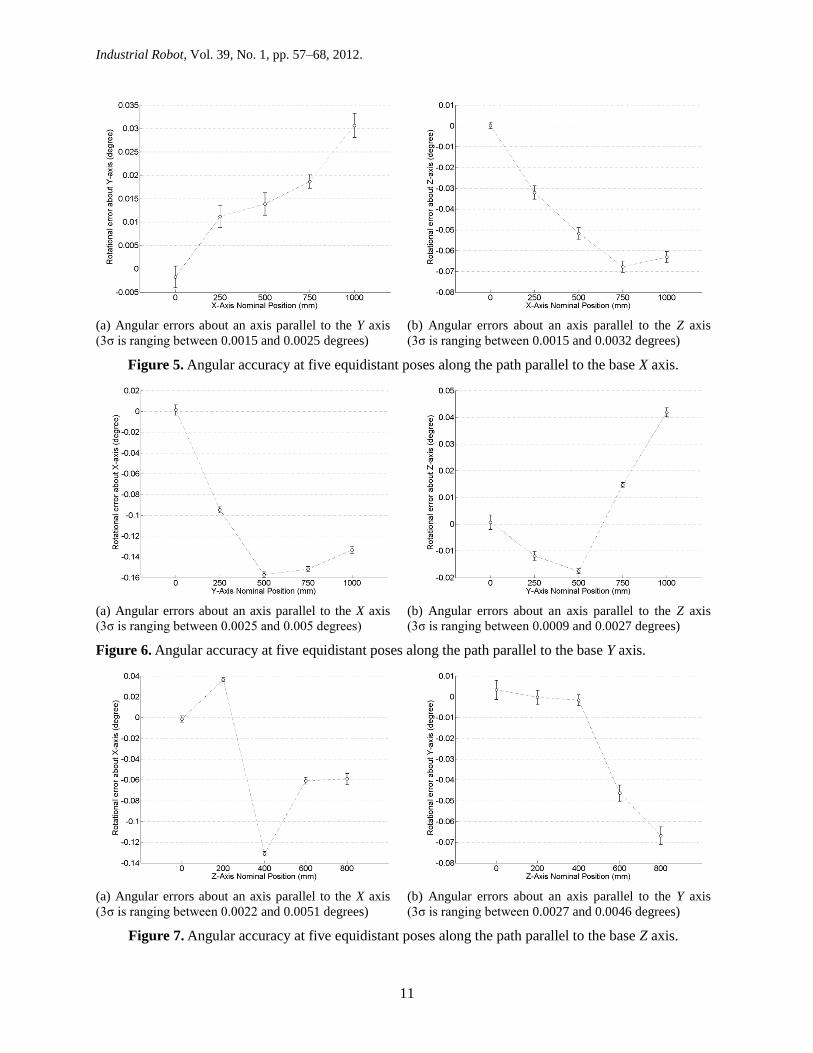
We will first start with orientation errors, which are never specified by the manufacturers of in-
dustrial robots. Figures 5, 6 and 7 show both the orientation accuracy and the orientation repeat-
ability along the three linear paths. As already mentioned, the orientation about an axis parallel to
the path of motion cannot be measured with the laser interferometer system.
It is logical to speculate that the orientation errors of the common industrial robot are most-
ly due to errors in the wrist joints, since there is a long and complex gear train between the robot
wrist axes and the corresponding motors and since the gear reduction ratios are much smaller
(while the motor encoders are the same). Results show that the unidirectional orientation repeat-
ability in all six setups is relatively the same and less than 0.005° (87 μrad).
The orientation accuracy, however, varies significantly between the six angular measure-
ment setups. A closer look at the results reveals that the orientation accuracy about an axis paral-
lel to the base X axis is by far the worst, as large as 0.16° (2.8 mrad). Indeed, this accuracy is the
only one directly dependent on the accuracy of joint 6. In a previous unpublished study on the
calibration of the IRB 1600 robot with our FARO laser tracker, we have noticed a significant
non-linearity between the command rotation of joint 6 and the actual one. The present results
only confirm that joint 6 has the worst performance. Therefore, in precision operations, the effect
of this axis should be minimized by bringing the TCP as close as possible to the axis of joint 6.
Figure 8 shows the linear position errors along the three orthogonal paths. The position
unidirectional repeatability is between 6 µm and 14 µm for the two horizontal paths and between
23 µm and 27 µm for the vertical path. The first observation is that a laser tracker cannot always
be used to assess the repeatability of a medium-size industrial robot, due to its limited repeatabil-
ity of approximately 8 µm. In fact, even a digital indicator is not necessarily the most suitable
tool for studying the repeatability of some of today’s industrial robots, since its accuracy is at
best 3 µm.
Page 11
Industrial Robot, Vol. 39, No. 1, pp. 57–68, 2012.
11
(a) Angular errors about an axis parallel to the Y axis
(3σ is ranging between 0.0015 and 0.0025 degrees) (b) Angular errors about an axis parallel to the Z axis
(3σ is ranging between 0.0015 and 0.0032 degrees)
Figure 5. Angular accuracy at five equidistant poses along the path parallel to the base X axis.
(a) Angular errors about an axis parallel to the X axis
(3σ is ranging between 0.0025 and 0.005 degrees) (b) Angular errors about an axis parallel to the Z axis
(3σ is ranging between 0.0009 and 0.0027 degrees)
Figure 6. Angular accuracy at five equidistant poses along the path parallel to the base Y axis.
(a) Angular errors about an axis parallel to the X axis
(3σ is ranging between 0.0022 and 0.0051 degrees) (b) Angular errors about an axis parallel to the Y axis
(3σ is ranging between 0.0027 and 0.0046 degrees)
Figure 7. Angular accuracy at five equidistant poses along the path parallel to the base Z axis.
Page 12
Industrial Robot, Vol. 39, No. 1, pp. 57–68, 2012.
12
(a) Linear position errors along the path parallel to the X axis
(3σ is ranging between 6 µm and 11 µm)
(b) Linear position errors along the path parallel to the Y axis
(3σ is ranging between 6 and 14 µm)
(c) Linear position errors along the path parallel to the Z axis
(3σ is ranging between 23 µm and 27 µm)
Figure 8. Linear position errors at five equidistant poses along each of the three paths.
Page 13
Industrial Robot, Vol. 39, No. 1, pp. 57–68, 2012.
13
It is logical that the position repeatability is not only dependant on the pose (and configu-
ration) of the robot, but also on the direction of arrival. Indeed, it can be seen that the repeatabil-
ity at pose P0 is much worse for the vertical path. This could be due to the fact that the wrist is
close to singularity along the vertical path. However, tests along different vertical paths, far from
wrist singularities, revealed similar if not worse repeatability (as much as 40 µm). Therefore, the
best hypothesis seems to be that joint 2 has a large influence on the robot unidirectional position
repeatability.
The results in Fig. 8 also show that the linear position accuracy along the three paths is
better than 650 µm over a distance as long as 1 m. (It is interesting to note that the linear position
error tests were performed on another identical IRB 1600 robot, purchased at the same time and
used in an undergraduate robotics lab, and that the results at each pose were very similar.) On the
other hand, we also realize that the laser interferometer is not suitable for the accuracy assess-
ment of the typical six-axis industrial robot, because it is unnecessarily too precise, elaborate to
setup, and mostly because it does only one-dimensional measurements. Furthermore, while the
robot repeatability remains virtually the same when the path is slightly changed, the robot accu-
racy may change abruptly.
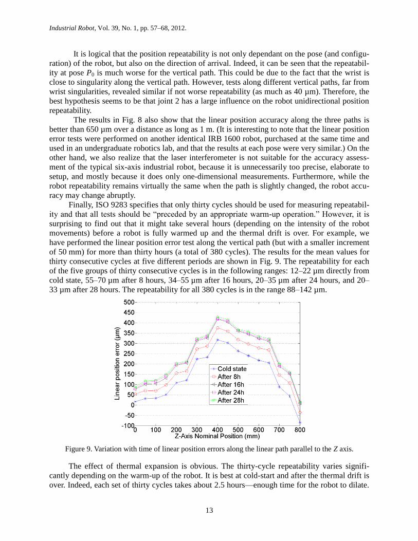
Finally, ISO 9283 specifies that only thirty cycles should be used for measuring repeatabil-
ity and that all tests should be “preceded by an appropriate warm-up operation.” However, it is
surprising to find out that it might take several hours (depending on the intensity of the robot
movements) before a robot is fully warmed up and the thermal drift is over. For example, we
have performed the linear position error test along the vertical path (but with a smaller increment
of 50 mm) for more than thirty hours (a total of 380 cycles). The results for the mean values for
thirty consecutive cycles at five different periods are shown in Fig. 9. The repeatability for each
of the five groups of thirty consecutive cycles is in the following ranges: 12–22 µm directly from
cold state, 55–70 µm after 8 hours, 34–55 µm after 16 hours, 20–35 µm after 24 hours, and 20–
33 µm after 28 hours. The repeatability for all 380 cycles is in the range 88–142 µm.
Figure 9. Variation with time of linear position errors along the linear path parallel to the Z axis.
The effect of thermal expansion is obvious. The thirty-cycle repeatability varies signifi-
cantly depending on the warm-up of the robot. It is best at cold-start and after the thermal drift is
over. Indeed, each set of thirty cycles takes about 2.5 hours—enough time for the robot to dilate.
Page 14
Industrial Robot, Vol. 39, No. 1, pp. 57–68, 2012.
14
This thermal expansion is clearly over after 24 hours, which is why the thirty-cycle repeatability
gets smaller and relatively constant after 24 hours. Since the thirty-cycle repeatability is best
immediately after cold start, it seems that the thermal expansion is very small during the first two
hours and half of operation.
It is therefore important to note that if a robot is to repeat a given pose from cold state for
several hours, the long-term repeatability will be much worse than the repeatability measured for
thirty consecutive cycles only. In other words, whenever precision operations are necessary, the
robot should be warmed up for several hours. To the best of our knowledge, the thermal drift is
never considered in today’s robot commercial calibration procedures as offered by ABB or Dyna-
log, for example. It is, however, studied in detail in some research works such as that performed
by Eastwood and Webb (2009).
Telescopic ballbar results
A circular test with the telescopic ballbar returns a series of measurement values in the (approx-
imate) range [−1 mm, 1 mm]. We then add the nominal radius (i.e., the length of the ballbar at
which it reads a zero error) to these values to obtain the actual circular path (in a Cartesian refer-
ence frame) and fit a least-squares circle, in order to estimate the actual center of the circular
path (which is usually offset by several tens of microns with respect to the taught center posi-
tion). A circle of nominal radius is then constructed at the least-squares circle center and errors
are considered with respect to this nominal circle. The radius size error is defined as the radius
of the least-squares circle minus the nominal radius. The out-of-roundness is defined as the dif-
ference between the largest and smallest radial distance from the least-squares circle center to the
actual circular path.
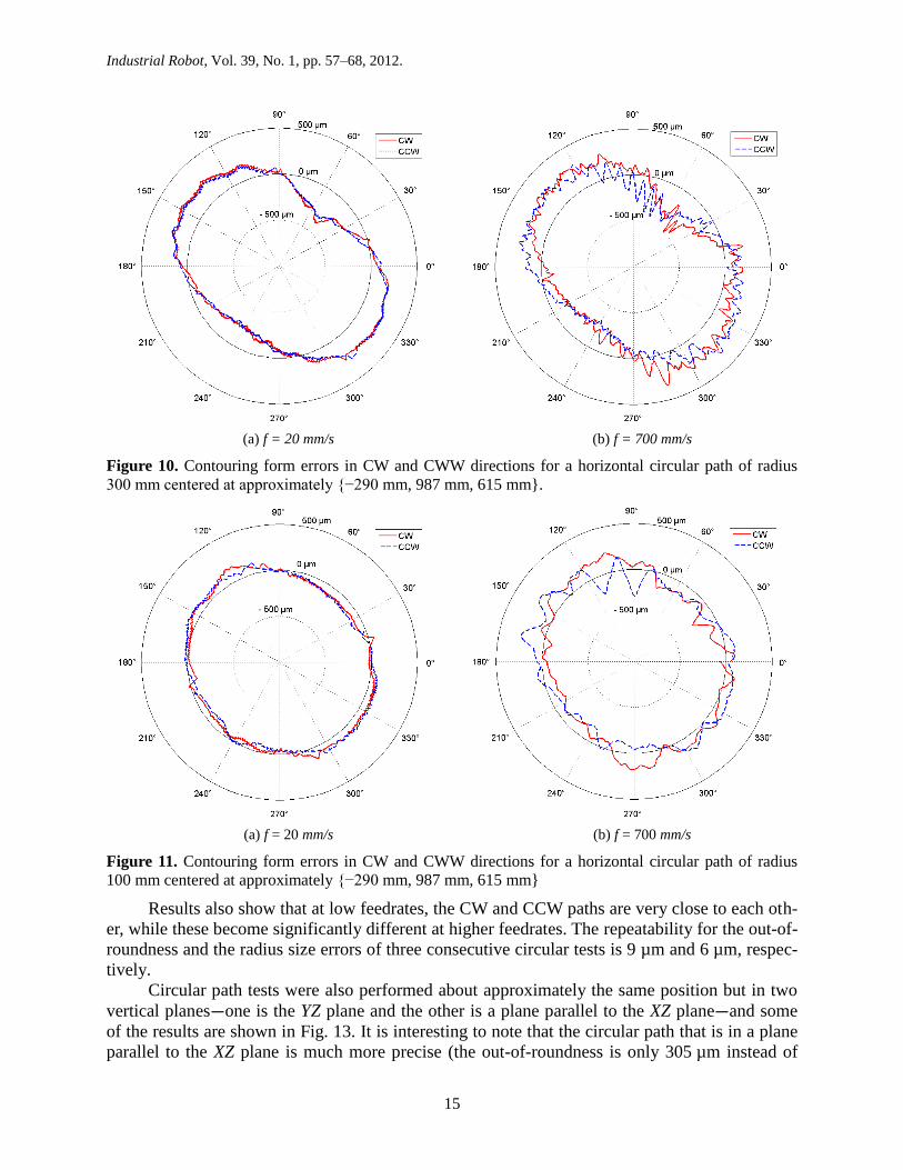
Figures 10 and 11 show the contouring form errors (radial errors) with respect to the nom-
inal circle, for both CW and CCW directions, at feed rates of 20 mm/s and 700 mm/s and for
nominal radii of 300 mm and 100 mm. The circular paths are centered at approximately {−290
mm, 987 mm, 615 mm} with respect to the robot base reference frame, and lie in a horizontal
plane. Results show that in the circular paths with large radius, the geometric errors are the prin-
cipal source of errors affecting the out-of-roundness whatever the feedrate. In the circular paths
with small radius, the geometric errors remain the principal source of errors affecting the out-of-
roundness at low feedrates. At high feedrates, the dynamic errors become an important source of
errors which affect out-of-roundness. This is represented by vibrations along the measured path
which strongly affect the accuracy of the robot. This behavior is explained by the poor rigidity,
coming from the joints flexibilities, which induces vibrations of the end-effector.
It is important to note that the dynamic performance of an industrial robot is even less ho-
mogeneous than its static performance. Obviously, the less are the main joints (especially joint
1) displaced, the better the dynamic performance of the robot. In fact, according to ABB, the best
small circular paths are achieved when only two wrist joints are moved.
Figure 12(a) shows the radius size error for all feedrates and nominal radii tested on the ro-
bot. Large radius size errors are present at low feedrates due to the effect of the geometric errors.
The radius size error increases (negatively) with the feedrate due to servo dynamic errors. Simi-
larly, Fig. 12(b) shows that the out-of-roundness increases with the feedrate, due to the effect of
vibrations.
Page 15
Industrial Robot, Vol. 39, No. 1, pp. 57–68, 2012.
15
(a) f = 20 mm/s
(b) f = 700 mm/s
Figure 10. Contouring form errors in CW and CWW directions for a horizontal circular path of radius
300 mm centered at approximately {−290 mm, 987 mm, 615 mm}.
(a) f = 20 mm/s
(b) f = 700 mm/s
Figure 11. Contouring form errors in CW and CWW directions for a horizontal circular path of radius
100 mm centered at approximately {−290 mm, 987 mm, 615 mm}
Results also show that at low feedrates, the CW and CCW paths are very close to each oth-
er, while these become significantly different at higher feedrates. The repeatability for the out-of-
roundness and the radius size errors of three consecutive circular tests is 9 µm and 6 µm, respec-
tively.
Circular path tests were also performed about approximately the same position but in two
vertical planes—one is the YZ plane and the other is a plane parallel to the XZ plane—and some
of the results are shown in Fig. 13. It is interesting to note that the circular path that is in a plane
parallel to the XZ plane is much more precise (the out-of-roundness is only 305 µm instead of
Page 16
Industrial Robot, Vol. 39, No. 1, pp. 57–68, 2012.
16
791 µm). It is also important to mention that for the circular path in the YZ plane, only robot axes
2, 3 and 5 are moving. Indeed, in the typical six-axis industrial robot, and using the typical pro-
gramming language commands (MoveC, in the case of ABB robots), it is impossible to produce a
circular motion at the TCP with only two robot axes (only the robot manufacturer can develop
such an option). Thus, a circular motion in a plane passing through the Z axis (i.e., through axis
1) and with a constant end-effector orientation is the best a robot user can do to minimize the
number of axes in motion and thus be able to interpret the results more easily. While it is obvious
that axes 2 and 3, under the gravitational effect, are those most responsible for the robot position-
ing errors, and their motion should be minimized, it seems impossible to promptly explain the
excellent accuracy in the circular path parallel to the XZ plane.
(a) radius size error
(a) out-of-roundness error
Figure 12. Contouring form errors as function of programmed feedrate for horizontal circular path of
various radii centered at approximately {−290 mm, 987 mm, 615 mm}.
(a) Circular path in YZ plane
(centered at {0 mm, 935 mm, 1069 mm})
(b) Circular path parallel to XZ plane
(centered at {−294 mm, 898 mm, 780 mm})
Figure 13. Contouring form errors in CW and CWW directions for a radius of 300 mm and at feedrate
20 mm/s in two different planes.
Page 17
Industrial Robot, Vol. 39, No. 1, pp. 57–68, 2012.
17
It is therefore obvious the test procedure offered by the telescopic ballbar software (two
CW runs followed by two CCW runs along the same circular path), and designed particularly for
testing a serial arrangement of two perpendicular linear guides, is inadequate for testing the static
performance of an industrial robot. Indeed, the only static performance criteria that should be
measured on a six-axis industrial using a telescopic ballbar is the distance accuracy and the dis-
tance repeatability about a given position. Instead of following a circular path, the robot should
go to a number of positions on a sphere and each time the distance error should be recorded.
Since the ballbar should remain in its measurement range ([−1 mm, 1 mm] in the case of the
Renishaw ballbar) at all times, the point-to-point trajectories along the sphere should be circular
(rather than using linear or joint interpolation). Results can either be represented individually
(e.g., using a 3D vector plot on a sphere) or as a group (e.g., mean distance error about a given
position). Furthermore, ideally the coordinates of the measurement point (i.e., the center of the
tool cup) with respect to the robot flange should be known precisely, in which case the orienta-
tion of the end-effector can be varied. In any case, for such test to be performed using the Ren-
ishaw toolbar, it is necessary to code a few lines and rely on the ballbar’s SDK.
Finally, note that, in the case of ABB robots, the positioning performance at low speeds
(less than 100 mm/s) and along complex paths (e.g., small circles) can be improved by using
optional controller software (Advanced Shape Tuning) that we do not have, however. This soft-
ware takes into account the friction effect, which, as an example, is clearly visible in the upper-
left part of the CW curve of Fig. 13a. Note also that the TCP speed is generally limited to
100 mm/s, in robot laser cutting, and to 300 mm/s, in water-jet cutting.
Conclusions
In this paper, an experimental approach is presented to assess the static accuracy and static re-
peatability and quantify the relative contributions of geometric and dynamic errors at different
feedrates for a six-axis non-calibrated ABB IRB 1600 industrial robot. The static errors are
measured using a laser tracker, at five poses, and using a laser interferometer system, along three
orthogonal paths. The dynamic errors are measured along continuous circular paths, at different
feedrates and at different radii, using a telescopic ballbar.
The following observations were made:
– While the FARO laser tracker (without laser interferometer option) is highly versatile
and simple to use, its relatively poor repeatability of at least 8 µm makes it unsuitable
for a comprehensive assessment of the pose repeatability of medium-size industrial ro-
bots. Other portable 3D measurement systems (e.g., Dynalog’s 3D CompuGauge or
Nikon Metrology’s K-series optical CMM) have worse repeatability and are therefore
even less suitable for comprehensive repeatability assessments of some industrial ro-
bots. However, the laser tracker remains undoubtedly the best tool for assessing robot
accuracy, using nearly any of the performance criteria described in the ISO 9283:98
norm.
– Using the FARO laser tracker, the position repeatability of our IRB1600-6/1.45 robot
at five poses along an inclined plane was found to be between 22 µm and 37 µm. The
repeatability was naturally worse for the two poses that are closer to the workspace
boundary, which suggests that the inclined plane ISO 9283:98 test is probably not the
best for evaluating robot repeatability.
– Using Renishaw’s laser interferometer system, the position repeatability at several
poses along three orthogonal linear paths was found to be in the range 6–14 µm, for
Page 18
Industrial Robot, Vol. 39, No. 1, pp. 57–68, 2012.
18
horizontal paths, and about as much as 25 µm for a vertical path (possibly due to
joint 2), while the orientation repeatability was better than 0.005° (87 μrad). The linear
position accuracy was found to be better than 650 µm, while the worst orientation ac-
curacy was found to be about 0.16° (2.8 mrad), mainly due to robot’s joint 6. It was al-
so demonstrated that it may take up to 24 hours, before the thermal drift is over, and
the thermal expansion due to the warm-up of the motors can contribute a further
100 µm to the TCP error.
– It is clear that the laser interferometer has the optimal accuracy for evaluating the re-
peatability of a medium-size industrial robot (along a linear path), yet none of the per-
formance criteria described in ISO 9283:98 can be measured using a laser interferome-
ter. It also seems that the laser interferometer is overkill (too complex to use, quite ex-
pensive and too accurate) for measuring the accuracy of an industrial robot (even if
that robot is calibrated).
– Finally, using a Renishaw telescopic ballbar, it was shown that, at low feedrates, the
out-of-roundness error can be nearly 1 mm along a circular trajectory of radius
300 mm.
– It seems that, in the case of industrial robots, the circular ballbar test is inadequate for
assessing static accuracy or repeatability. The only static performance criterion that
should be evaluated using a ballbar is distance accuracy about a point, which however
requires some coding in the case of Renishaw’s ballbar.
– Finally, while the dynamic performance of an industrial robot can be measured with
any of the three instruments, the ballbar seems to be the optimal choice.
It is important to note again that most of our test results can be significantly improved us-
ing optional controller functionalities and calibration offered by ABB.
This paper also illustrated the complexity involved in assessing the positioning perfor-
mance of an industrial robot. Even if most industrial robot manufacturers adopt the ISO 9283
norm, they will hardly ever specify more than a few measures such as unidirectional position
repeatability or path accuracy. Indeed, not only does a rigorous application of the ISO 9283 norm
call for the production of a detailed report of dozens of pages, but it also reveals results that
might be poorly interpreted by potential clients. It is therefore of paramount importance for in-
dustrial robot users interested in precision applications to fully understand the test methods used
for assessing robot positioning performance and the conditions that maximize that positioning
performance.
We believe that the ISO 9283 five-pose test for repeatability assessment is inadequate.
Since position repeatability remains the single most important performance measure for industri-
al robots, its assessments should be much more comprehensive. Indeed, our future work will be
dedicated on studying the robot position repeatability in a highly comprehensive manner with a
laser interferometer and proposing new guidelines for precisely assessing robot position repeata-
bility.
Finally, we should note that our work is also limited in terms of thermal drift evaluation. A
much more comprehensive study of thermal errors should be performed, as already done by
Eastwood and Webb (2009), in the case of a parallel robot. Also, performance testing should not
only yield a single worse-case value but at least propose specific ways for improving this value
(e.g., by warming up the robot, or by minimizing the use of some of the robot axes). These topics
will be the subject of future research.
Page 19
Industrial Robot, Vol. 39, No. 1, pp. 57–68, 2012.
19
Acknowledgements
This work was supported by the Canada Research Chairs program and the Canada Foundation
for Innovation. The authors would also like to thank Dr. Torgny Brogardh, senior specialist at
ABB Robotics, for his valuable help, as well as the anonymous reviewers.
References
Abderrahim, M., Khamis, A., Garrido, S. and Moreno, L. (2006), “Accuracy and calibration is-
sues of industrial manipulators”, Industrial Robotics: Programming, Simulation and Applica-
tions, Pro Literatur Verlag.
Brethé, J.-F., Vasselin, E., Lefebvre, D. and Dakyo, B. (2006), “Modelling of repeatability phe-
nomena using the stochastic ellipsoid approach”, Robotica, Vol. 24, No. 4, pp. 477-490.
Eastwood, S.J. (2004), “Error mapping and analysis for hybrid kinematic machines”, The Uni-
versity of Nottingham, Nottingham, PhD thesis.
Eastwood, S. and Webb, P. (2009), “Error significance analysis and compensation for HPKMs”,
Industrial Robot: An International Journal, Vol. 36, No. 1, pp. 27-35.
Greenway, B. (2000), “Robot accuracy”, Industrial Robot: An International Journal, Vol. 27,
No. 4, pp. 257-265.
ISO 9283 (1998), Manipulating industrial robots—Performance criteria and related test meth-
ods.
ISO TR 13309 (1995), Manipulating industrial robots—Informative guide on test equipment and
metrology methods of operation for robot performance evaluation in accordance with ISO
9283.
Karlsson, B. and Brogårdh, T. (2001), “A new calibration method for industrial robots”, Robot-
ica, Vol. 19, No. 6.
Lei, W. T., Paung, I. M. and Yu, C.-C. (2009), “Total ballbar dynamic tests for five-axis CNC
machine tools”, International Journal of Machine Tools & Manufacture, Vol. 49, No. 6,
pp. 488–499
Muelaner, J. E., Wang, Z. and Maropoulos, P. G. (2010), “Concepts for and analysis of a high
accuracy and high capacity (HAHC) aerospace robot”, The 21st International Computer-
Aided Production Engineering Conference (CAPE 2010), Edinburgh, UK.
Ota, H., Shibukawa, T. and Uchiyama, M. (2000), “Forward kinematic calibration method for
parallel mechanism using pose data measured by a double ball bar system”, Proceedings of
the Year 2000 Parallel Kinematic Machines International Conference, pp. 57-62.
Schröer, K. (1999), “Precision and calibration”, Handbook of Industrial Robotics, 2nd
ed., John
Wiley & Sons.
Summers, M., (2005) “Robot capability test and development of industrial robot positioning sys-
tem for the aerospace industry”, SAE 2005 AeroTech Congress & Exhibition, Grapevine, TX,
USA, Paper No. 2005-01-3336.
Vira, N. and Lau, K. (1987), “An extensible ball bar for evaluation of robots’ positioning perfor-
mance”, Journal of Robotic Systems, Vol. 4 No. 6, pp. 799-814.
Young, K. and Pickin, C. G. (2000), “Accuracy assessment of the modern industrial robot”, In-
dustrial Robot: An International Journal, Vol. 27, No. 6, pp. 427-436.