136
GA 90, GA 110, GA 132, GA 160, GA 200, GA 250, GA 315 Instruction book
| Date post: | 21-Dec-2015 |
| Category: |
Documents |
| Upload: | manojmeena |
| View: | 1,050 times |
| Download: | 202 times |
GA 90, GA 110, GA 132, GA 160, GA 200, GA 250, GA 315
Instruction book

Atlas Copco
GA 90, GA 110, GA 132, GA 160, GA 200, GA 250, GA 315
Instruction bookOriginal instructions
Copyright NoticeAny unauthorized use or copying of the contents or any part thereof is prohibited.
This applies in particular to trademarks, model denominations, part numbers and drawings.
This instruction book is valid for CE as well as non-CE labelled machines. It meets therequirements for instructions specified by the applicable European directives as identifiedin the Declaration of Conformity.
2010 - 03
No. 2920 1475 06
www.atlascopco.com
Table of contents
1 Safety precautions..........................................................................................................5
1.1 SAFETY ICONS...................................................................................................................................5
1.2 SAFETY PRECAUTIONS, GENERAL...........................................................................................................5
1.3 SAFETY PRECAUTIONS DURING INSTALLATION...........................................................................................5
1.4 SAFETY PRECAUTIONS DURING OPERATION..............................................................................................7
1.5 SAFETY PRECAUTIONS DURING MAINTENANCE OR REPAIR...........................................................................8
2 General description......................................................................................................10
2.1 INTRODUCTION.................................................................................................................................10
2.2 AIR AND OIL SYSTEM.........................................................................................................................14
2.3 COOLING AND CONDENSATE SYSTEM....................................................................................................17
2.4 REGULATING SYSTEM........................................................................................................................19
3 Elektronikon regulator.................................................................................................22
3.1 ELEKTRONIKON® REGULATOR.............................................................................................................22
3.2 CONTROL PANEL..............................................................................................................................24
3.3 FUNCTION KEYS...............................................................................................................................25
3.4 SCROLL KEYS..................................................................................................................................26
3.5 EMERGENCY STOP BUTTON................................................................................................................26
3.6 CONTROL PROGRAMS........................................................................................................................27
3.7 CALLING UP MENUS..........................................................................................................................30
3.8 MAIN SCREEN MENU.........................................................................................................................31
3.9 STATUS DATA MENU..........................................................................................................................32
3.10 MEASURED DATA MENU.....................................................................................................................35
3.11 COUNTERS MENU.............................................................................................................................36
3.12 TEST MENU.....................................................................................................................................37
3.13 MODIFY PARAMETERS MENU...............................................................................................................37
3.14 MODIFYING PARAMETERS...................................................................................................................38
Instruction book
2 2920 1475 06
3.15 MODIFYING PROTECTION SETTINGS......................................................................................................39
3.16 MODIFYING SERVICE PLANS................................................................................................................40
3.17 PROGRAMMING CLOCK FUNCTION.........................................................................................................41
3.18 MODIFYING CONFIGURATION SETTINGS..................................................................................................45
3.19 SERVICE MENU................................................................................................................................47
3.20 SAVED DATA MENU...........................................................................................................................49
3.21 PROGRAMMABLE SETTINGS FOR GA90 UP TO GA500...........................................................................49
4 Installation.....................................................................................................................54
4.1 DIMENSION DRAWING........................................................................................................................54
4.2 INSTALLATION PROPOSAL...................................................................................................................61
4.3 ELECTRIC CABLE SIZE.......................................................................................................................67
4.4 PICTOGRAPHS.................................................................................................................................69
4.5 COOLING WATER REQUIREMENTS.........................................................................................................70
5 Operating instructions.................................................................................................75
5.1 INITIAL START-UP..............................................................................................................................75
5.2 BEFORE STARTING............................................................................................................................81
5.3 STARTING.......................................................................................................................................82
5.4 DURING OPERATION..........................................................................................................................84
5.5 CHECKING THE DISPLAY.....................................................................................................................85
5.6 MANUAL LOADING/UNLOADING.............................................................................................................86
5.7 STOPPING.......................................................................................................................................87
5.8 TAKING OUT OF OPERATION................................................................................................................88
5.9 USE OF AIR RECEIVER.......................................................................................................................89
6 Maintenance..................................................................................................................90
6.1 PREVENTIVE MAINTENANCE SCHEDULE..................................................................................................90
6.2 MOTORS.........................................................................................................................................91
6.3 OIL SPECIFICATIONS..........................................................................................................................92
Instruction book
2920 1475 06 3
6.4 OIL CHANGE....................................................................................................................................93
6.5 OIL FILTER CHANGE..........................................................................................................................98
6.6 STORAGE AFTER INSTALLATION.........................................................................................................101
6.7 SERVICE KITS................................................................................................................................101
7 Adjustments and servicing procedures...................................................................103
7.1 AIR FILTERS..................................................................................................................................103
7.2 COOLERS.....................................................................................................................................105
7.3 SAFETY VALVE...............................................................................................................................106
8 Problem solving..........................................................................................................108
8.1 PROBLEM SOLVING.........................................................................................................................108
9 Technical data.............................................................................................................111
9.1 READINGS ON DISPLAY....................................................................................................................111
9.2 REFERENCE CONDITIONS.................................................................................................................112
9.3 LIMITS..........................................................................................................................................112
9.4 SETTINGS OF SAFETY VALVE.............................................................................................................113
9.5 SETTINGS FOR OVERLOAD RELAY AND FUSES.......................................................................................113
9.6 SETTINGS OF CIRCUIT BREAKERS.......................................................................................................115
9.7 COMPRESSOR DATA........................................................................................................................121
10 Pressure equipment directives.................................................................................129
11 Documentation............................................................................................................130
Instruction book
4 2920 1475 06

1 Safety precautions
1.1 Safety icons
Explanation
Danger for life
Warning
Important note
1.2 Safety precautions, general
General precautions
1. The operator must employ safe working practices and observe all related work safety requirements andregulations.
2. If any of the following statements does not comply with the applicable legislation, the stricter of the twoshall apply.
3. Installation, operation, maintenance and repair work must only be performed by authorized, trained,specialized personnel.
4. The compressor is not considered capable of producing air of breathing quality. For air of breathing quality,the compressed air must be adequately purified according to the applicable legislation and standards.
5. Before any maintenance, repair work, adjustment or any other non-routine checks, stop the compressor,press the emergency stop button, switch off the voltage and depressurize the compressor. In addition, thepower isolating switch must be opened and locked.
6. Never play with compressed air. Do not apply the air to your skin or direct an air stream at people. Neveruse the air to clean dirt from your clothes. When using the air to clean equipment, do so with extremecaution and wear eye protection.
7. The owner is responsible for maintaining the unit in safe operating condition. Parts and accessories shallbe replaced if unsuitable for safe operation.
8. It is not allowed to walk or stand on the roof of the compressor canopy.
1.3 Safety precautions during installation
All responsibility for any damage or injury resulting from neglecting these precautions, ornon-observance of the normal caution and care required for installation, operation,maintenance and repair, even if not expressly stated, will be disclaimed by themanufacturer.
Instruction book
2920 1475 06 5
Precautions during installation
1. The machine must only be lifted using suitable equipment in accordance with the applicable safetyregulations. Loose or pivoting parts must be securely fastened before lifting. It is strictly forbidden todwell or stay in the risk zone under a lifted load. Lifting acceleration and deceleration must be kept withinsafe limits. Wear a safety helmet when working in the area of overhead or lifting equipment.
2. Place the machine where the ambient air is as cool and clean as possible. If necessary, install a suctionduct. Never obstruct the air inlet. Care must be taken to minimize the entry of moisture at the inlet air.
3. Any blanking flanges, plugs, caps and desiccant bags must be removed before connecting the pipes.4. Air hoses must be of correct size and suitable for the working pressure. Never use frayed, damaged or
worn hoses. Distribution pipes and connections must be of the correct size and suitable for the workingpressure.
5. The aspirated air must be free of flammable fumes, vapours and particles, e.g. paint solvents, that can leadto internal fire or explosion.
6. Arrange the air intake so that loose clothing worn by people cannot be sucked in.7. Ensure that the discharge pipe from the compressor to the aftercooler or air net is free to expand under
heat and that it is not in contact with or close to flammable materials.8. No external force may be exerted on the air outlet valve; the connected pipe must be free of strain.9. If remote control is installed, the machine must bear a clear sign stating: DANGER: This machine is
remotely controlled and may start without warning.The operator has to make sure that the machine is stopped and that the isolating switch is open and lockedbefore any maintenance or repair. As a further safeguard, persons switching on remotely controlledmachines shall take adequate precautions to ensure that there is no one checking or working on themachine. To this end, a suitable notice shall be affixed to the start equipment.
10. Air-cooled machines must be installed in such a way that an adequate flow of cooling air is available andthat the exhausted air does not recirculate to the compressor air inlet or cooling air inlet.
11. The electrical connections must correspond to the applicable codes. The machines must be earthed andprotected against short circuits by fuses in all phases. A lockable power isolating switch must be installednear the compressor.
12. On machines with automatic start/stop system or if the automatic restart function after voltage failure isactivated, a sign stating "This machine may start without warning" must be affixed near the instrumentpanel.
13. In multiple compressor systems, manual valves must be installed to isolate each compressor. Non-returnvalves (check valves) must not be relied upon for isolating pressure systems.
14. Never remove or tamper with the safety devices, guards or insulation fitted on the machine. Every pressurevessel or auxiliary installed outside the machine to contain air above atmospheric pressure must beprotected by a pressure-relieving device or devices as required.
15. Piping or other parts with a temperature in excess of 80˚C (176˚F) and which may be accidentally touchedby personnel in normal operation must be guarded or insulated. Other high-temperature piping must beclearly marked.
16. For water-cooled machines, the cooling water system installed outside the machine has to be protected bya safety device with set pressure according to the maximum cooling water inlet pressure.
17. If the ground is not level or can be subject to variable inclination, consult the manufacturer.
Also consult following safety precautions: Safety precautions during operation and Safetyprecautions during maintenance.These precautions apply to machinery processing or consuming air or inert gas.Processing of any other gas requires additional safety precautions typical to the applicationwhich are not included herein.Some precautions are general and cover several machine types and equipment; hencesome statements may not apply to your machine.
Instruction book
6 2920 1475 06

1.4 Safety precautions during operation
All responsibility for any damage or injury resulting from neglecting these precautions, ornon-observance of the normal caution and care required for installation, operation,maintenance and repair, even if not expressly stated, will be disclaimed by themanufacturer.
Precautions during operation
1. Never touch any piping or components of the compressor during operation.2. Use only the correct type and size of hose end fittings and connections. When blowing through a hose or
air line, ensure that the open end is held securely. A free end will whip and may cause injury. Make surethat a hose is fully depressurized before disconnecting it.
3. Persons switching on remotely controlled machines shall take adequate precautions to ensure that thereis no one checking or working on the machine. To this end, a suitable notice shall be affixed to the remotestart equipment.
4. Never operate the machine when there is a possibility of taking in flammable or toxic fumes, vapors orparticles.
5. Never operate the machine below or in excess of its limit ratings.6. Keep all bodywork doors shut during operation. The doors may be opened for short periods only, e.g. to
carry out routine checks. Wear ear protectors when opening a door.On compressors without bodywork, wear ear protection in the vicinity of the machine.
7. People staying in environments or rooms where the sound pressure level reaches or exceeds 80 dB(A)shall wear ear protectors.
8. Periodically check that:• All guards are in place and securely fastened• All hoses and/or pipes inside the machine are in good condition, secure and not rubbing• There are no leaks• All fasteners are tight• All electrical leads are secure and in good order• Safety valves and other pressure-relief devices are not obstructed by dirt or paint• Air outlet valve and air net, i.e. pipes, couplings, manifolds, valves, hoses, etc. are in good repair, free
of wear or abuse9. If warm cooling air from compressors is used in air heating systems, e.g. to warm up a workroom, take
precautions against air pollution and possible contamination of the breathing air.10. Do not remove any of, or tamper with, the sound-damping material.11. Never remove or tamper with the safety devices, guards or insulations fitted on the machine. Every pressure
vessel or auxiliary installed outside the machine to contain air above atmospheric pressure shall beprotected by a pressure-relieving device or devices as required.
Also consult following safety precautions: Safety precautions during installation and Safetyprecautions during maintenance.These precautions apply to machinery processing or consuming air or inert gas.Processing of any other gas requires additional safety precautions typical to the applicationwhich are not included herein.Some precautions are general and cover several machine types and equipment; hencesome statements may not apply to your machine.
Instruction book
2920 1475 06 7
1.5 Safety precautions during maintenance or repair
All responsibility for any damage or injury resulting from neglecting these precautions, ornon-observance of the normal caution and care required for installation, operation,maintenance and repair, even if not expressly stated, will be disclaimed by themanufacturer.
Precautions during maintenance or repair
1. Always use the correct safety equipment (such as safety glasses, gloves, safety shoes, etc.).2. Use only the correct tools for maintenance and repair work.3. Use only genuine spare parts.4. All maintenance work shall only be undertaken when the machine has cooled down.5. A warning sign bearing a legend such as "work in progress; do not start" shall be attached to the starting
equipment.6. Persons switching on remotely controlled machines shall take adequate precautions to ensure that there
is no one checking or working on the machine. To this end, a suitable notice shall be affixed to the remotestart equipment.
7. Close the compressor air outlet valve before connecting or disconnecting a pipe.8. Before removing any pressurized component, effectively isolate the machine from all sources of pressure
and relieve the entire system of pressure.9. Never use flammable solvents or carbon tetrachloride for cleaning parts. Take safety precautions against
toxic vapours of cleaning liquids.10. Scrupulously observe cleanliness during maintenance and repair. Keep dirt away by covering the parts
and exposed openings with a clean cloth, paper or tape.11. Never weld or perform any operation involving heat near the oil system. Oil tanks must be completely
purged, e.g. by steam-cleaning, before carrying out such operations. Never weld on, or in any way modify,pressure vessels.
12. Whenever there is an indication or any suspicion that an internal part of a machine is overheated, themachine shall be stopped but no inspection covers shall be opened before sufficient cooling time haselapsed; this to avoid the risk of spontaneous ignition of the oil vapour when air is admitted.
13. Never use a light source with open flame for inspecting the interior of a machine, pressure vessel, etc.14. Make sure that no tools, loose parts or rags are left in or on the machine.15. All regulating and safety devices shall be maintained with due care to ensure that they function properly.
They may not be put out of action.16. Before clearing the machine for use after maintenance or overhaul, check that operating pressures,
temperatures and time settings are correct. Check that all control and shut-down devices are fitted and thatthey function correctly. If removed, check that the coupling guard of the compressor drive shaft has beenreinstalled.
17. Every time the separator element is renewed, examine the discharge pipe and the inside of the oil separatorvessel for carbon deposits; if excessive, the deposits should be removed.
18. Protect the motor, air filter, electrical and regulating components, etc. to prevent moisture from enteringthem, e.g. when steam-cleaning.
19. Make sure that all sound-damping material and vibration dampers, e.g. damping material on the bodyworkand in the air inlet and outlet systems of the compressor, is in good condition. If damaged, replace it bygenuine material from the manufacturer to prevent the sound pressure level from increasing.
20. Never use caustic solvents which can damage materials of the air net, e.g. polycarbonate bowls.21. The following safety precautions are stressed when handling refrigerant:
• Never inhale refrigerant vapours. Check that the working area is adequately ventilated; if required, usebreathing protection.
Instruction book
8 2920 1475 06

• Always wear special gloves. In case of refrigerant contact with the skin, rinse the skin with water. Ifliquid refrigerant contacts the skin through clothing, never tear off or remove the latter; flushabundantly with fresh water over the clothing until all refrigerant is flushed away; then seek medicalfirst aid.
Also consult following safety precautions: Safety precautions during installation and Safetyprecautions during operation.These precautions apply to machinery processing or consuming air or inert gas.Processing of any other gas requires additional safety precautions typical to the applicationwhich are not included herein.Some precautions are general and cover several machine types and equipment; hencesome statements may not apply to your machine.
Instruction book
2920 1475 06 9

2 General description
2.1 Introduction
General
General view of GA90 up to GA160
Instruction book
10 2920 1475 06

General view of GA90W up to GA160 W
General view of GA200, GA250 and GA315 60 Hz
Instruction book
2920 1475 06 11

GA(W) and GR(W) are oil-injected screw compressors, driven by an electric motor and enclosed in sound-insulated bodywork.
GA110 up to GA500 and GR110 up to GR200 are air-cooled compressors.
GA110 W up to GA500 W and GR110 W up to GR200 W are water-cooled compressors.
GA are single-stage compressors.
The following features are available as an option:
Full-Feature
A refrigerant dryer is fully integrated into the bodywork of the compressor. This "all-in-one" feature reducesthe required space for installation and provides savings on piping installation costs.
DD filter
The compressor is provided with an integrated filter of the DD type to limit carry-over of solid particles andoil. By integrating a DD filter, the compressor delivers Quality Air according to ISO 8573-1, Class 2.4.2.
OSD
The OSD (Oil Separating Device) separates oil residues from condensate. The clean water can be dischargeddown the drain without any further treatment. The separated oil is collected and can be disposed of accordingto prevailing regulations.
Electronic drain
The EWD (Electronic Water Drain) assures proper draining of condensate and prevents water from enteringthe compressed air net. For any malfunction of the draining process, the EWD generates a warning messageon the display of the Elektronikon regulator.
Energy recovery
The compressor is provided with an Atlas Copco energy recovery system to recover the major part of thecompression heat in the form of hot water without any influence on the compressor performance.
Oil containing frame
This frame is installed under the machine and will collect oil from occasional leakage and avoid oil spreadingover the floor.
Modulating control
The modulating control system is designed to maintain a narrow net pressure band by throttling the air inlet,thus reducing the air flow (50% - 100%).
Heavy-duty air intake filter
A two-stage heavy-duty air intake filter is provided and allows the compressor to operate in heavilycontaminated surroundings (e.g. cement or mining industry). The larger dust particles are collected in the firststage of the filter. The filter efficiency (SAE fine) is 99% at 1 micrometer (0.0004 in) and 99.9% at 3micrometer (0.0012 in).
Instruction book
12 2920 1475 06
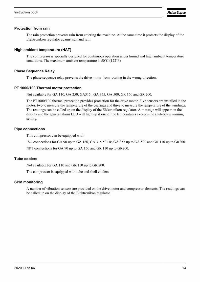
Protection from rain
The rain protection prevents rain from entering the machine. At the same time it protects the display of theElektronikon regulator against sun and rain.
High ambient temperature (HAT)
The compressor is specially designed for continuous operation under humid and high ambient temperatureconditions. The maximum ambient temperature is 50˚C (122˚F).
Phase Sequence Relay
The phase sequence relay prevents the drive motor from rotating in the wrong direction.
PT 1000/100 Thermal motor protection
Not available for GA 110, GA 250, GA315 , GA 355, GA 500, GR 160 and GR 200.
The PT1000/100 thermal protection provides protection for the drive motor. Five sensors are installed in themotor, two to measure the temperature of the bearings and three to measure the temperature of the windings.The readings can be called up on the display of the Elektronikon regulator. A message will appear on thedisplay and the general alarm LED will light up if one of the temperatures exceeds the shut-down warningsetting.
Pipe connections
This compressor can be equipped with:
ISO connections for GA 90 up to GA 160, GA 315 50 Hz, GA 355 up to GA 500 and GR 110 up to GR200.
NPT connections for GA 90 up to GA 160 and GR 110 up to GR200.
Tube coolers
Not available for GA 110 and GR 110 up to GR 200.
The compressor is equipped with tube and shell coolers.
SPM monitoring
A number of vibration sensors are provided on the drive motor and compressor elements. The readings canbe called up on the display of the Elektronikon regulator.
Instruction book
2920 1475 06 13

2.2 Air and oil system
Flow diagrams
Flow diagram of GA90 up to GA160
Instruction book
14 2920 1475 06
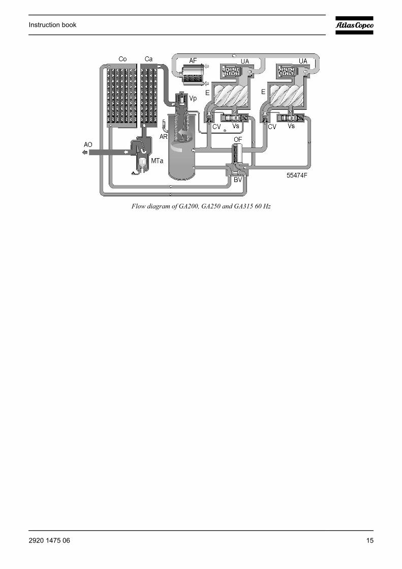
Flow diagram of GA200, GA250 and GA315 60 Hz
Instruction book
2920 1475 06 15

Flow diagram of air dryer on GA Full-Feature compressors
Air flow
Air drawn through filters (AF) and unloaders (UA) is compressed in compressor elements (E). Compressedair and oil are discharged through check valves (CV) to air receiver/oil separators (AR) where oil is separatedfrom the compressed air. The air is blown through minimum pressure valves (Vp) to air coolers (Ca).
On GA Pack compressors, the cooled air is discharged through condensate traps (MTa) and outlet (AO)towards the air net.
On GA Full-Feature compressors, the cooled air is discharged through condensate trap (MTa) and outlet (AO)towards the air net via the integrated air dryer.
Check valves (CV) prevent blow-back of compressed air.
Minimum pressure valve (Vp) prevents the receiver pressure from dropping below a minimum pressure. Thevalve has a built-in check valve.
Instruction book
16 2920 1475 06
Oil system
Air pressure forces the oil from receivers (AR) through oil coolers (Co), filters (OF) and oil stop valves (Vs)to compressor elements (E) and the lubrication points.
Oil stop valves (Vs) prevent the compressor elements from flooding with oil when the compressor is stopped.
Valves (BV) by-pass oil coolers (Co) when starting the compressor from a cold condition, so ensuring rapidwarming of the oil to normal working temperature.
In air receivers (AR) most of the oil is removed from the air centrifugally. Almost all of the remaining oil isremoved by the separator elements.
2.3 Cooling and condensate system
Condensate drain system
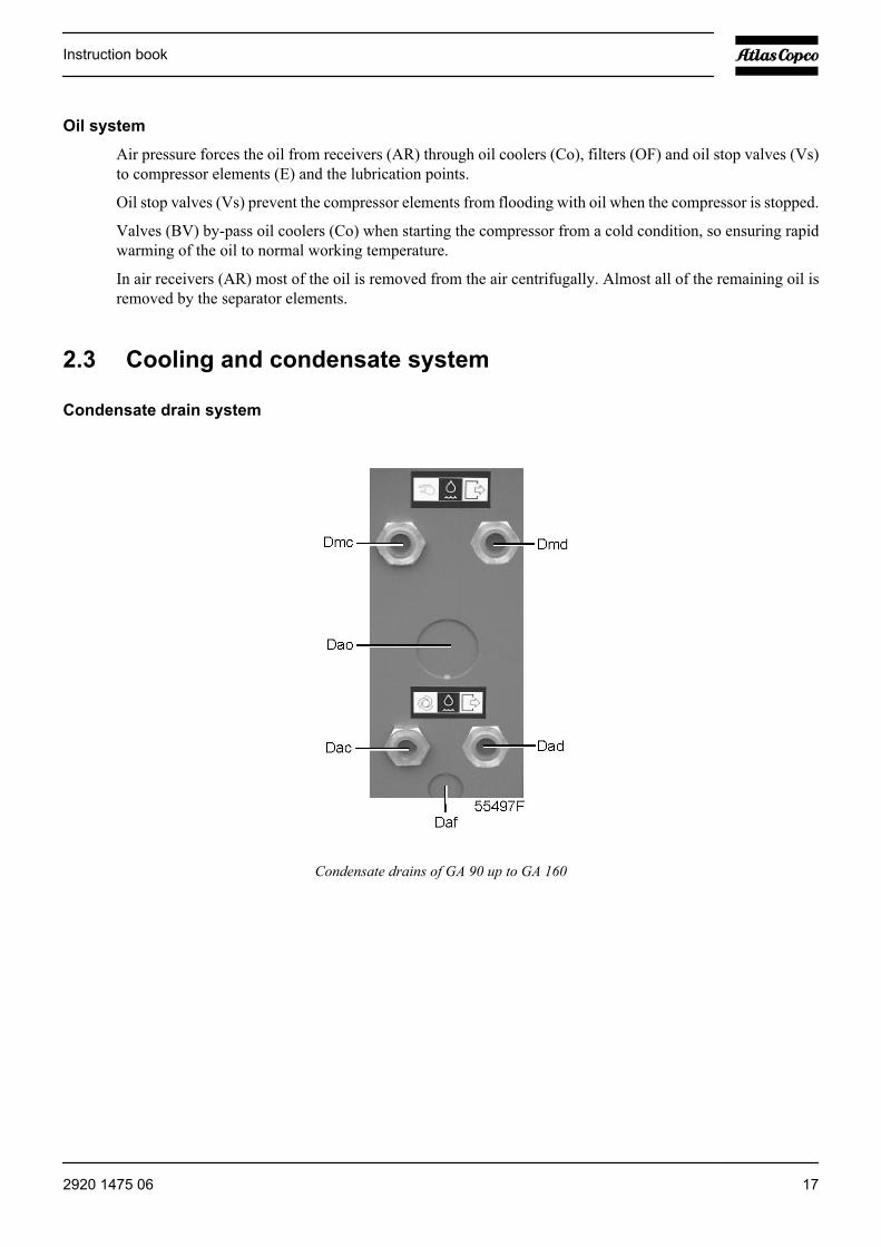
Condensate drains of GA 90 up to GA 160
Instruction book
2920 1475 06 17

Condensate drains of GA 200, GA 250 and GA 315 60 Hz
Dac Automatic condensate drain, compressorDad Automatic condensate drain, dryer (Full-Feature compressors only)Daf Automatic condensate drain, DD filter (option)Dao Automatic condensate drain, OSD (option)Dmc Manual condensate drainDmd Manual condensate drain, dryer (Full-Feature compressors only)
Condensate traps are installed downstream of the air coolers to prevent condensate from entering the air outletpipe. The traps are provided with a float valve for automatically draining condensate and with a manual drainvalve.
On Full-Feature compressors a condensate trap is also installed downstream of the dryer. This trap is alsoprovided with a float valve for automatically draining condensate and with a manual drain valve.
Cooling system
On air-cooled compressors, the air and oil coolers are cooled by fans.
Water-cooled compressors are provided with a cooling water system, including combined oil and air coolers.
Instruction book
18 2920 1475 06
2.4 Regulating system
Flow diagrams
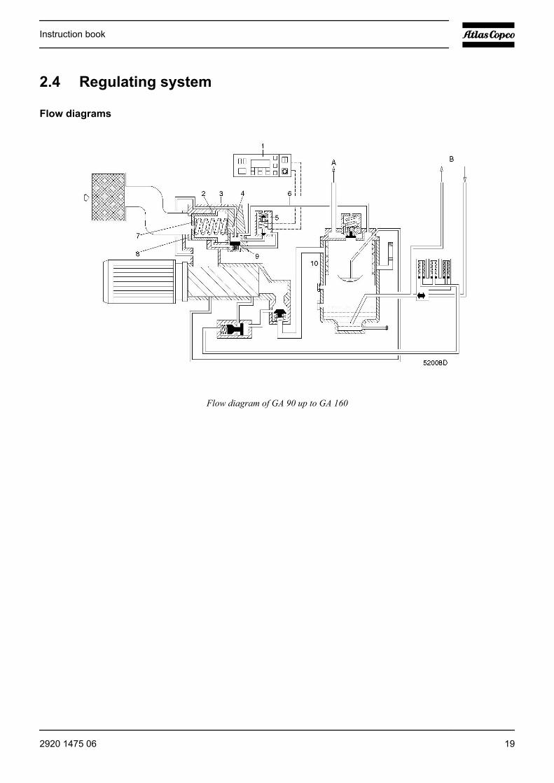
Flow diagram of GA 90 up to GA 160
Instruction book
2920 1475 06 19
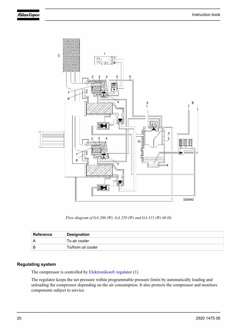
Flow diagram of GA 200 (W), GA 250 (W) and GA 315 (W) 60 Hz
Reference DesignationA To air coolerB To/from oil cooler
Regulating system
The compressor is controlled by Elektronikon® regulator (1)
The regulator keeps the net pressure within programmable pressure limits by automatically loading andunloading the compressor depending on the air consumption. It also protects the compressor and monitorscomponents subject to service.
Instruction book
20 2920 1475 06
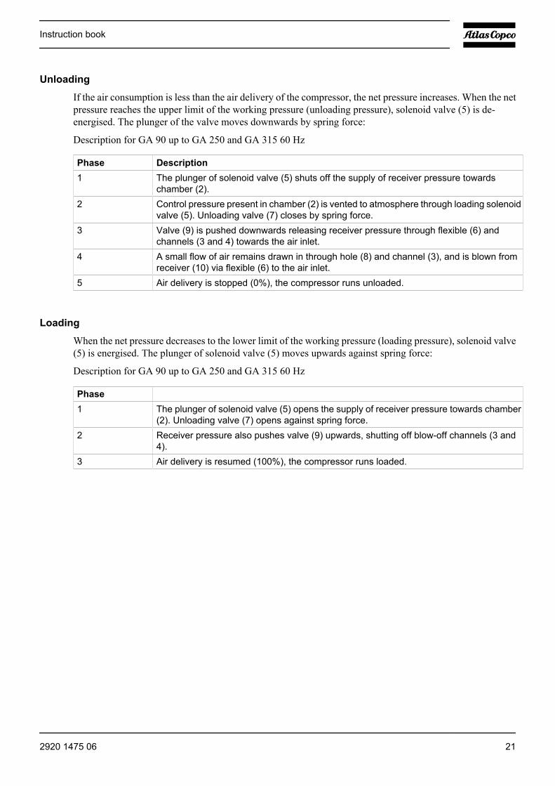
Unloading
If the air consumption is less than the air delivery of the compressor, the net pressure increases. When the netpressure reaches the upper limit of the working pressure (unloading pressure), solenoid valve (5) is de-energised. The plunger of the valve moves downwards by spring force:
Description for GA 90 up to GA 250 and GA 315 60 Hz
Phase Description1 The plunger of solenoid valve (5) shuts off the supply of receiver pressure towards
chamber (2).2 Control pressure present in chamber (2) is vented to atmosphere through loading solenoid
valve (5). Unloading valve (7) closes by spring force.3 Valve (9) is pushed downwards releasing receiver pressure through flexible (6) and
channels (3 and 4) towards the air inlet.4 A small flow of air remains drawn in through hole (8) and channel (3), and is blown from
receiver (10) via flexible (6) to the air inlet.5 Air delivery is stopped (0%), the compressor runs unloaded.
Loading
When the net pressure decreases to the lower limit of the working pressure (loading pressure), solenoid valve(5) is energised. The plunger of solenoid valve (5) moves upwards against spring force:
Description for GA 90 up to GA 250 and GA 315 60 Hz
Phase1 The plunger of solenoid valve (5) opens the supply of receiver pressure towards chamber
(2). Unloading valve (7) opens against spring force.2 Receiver pressure also pushes valve (9) upwards, shutting off blow-off channels (3 and
4).3 Air delivery is resumed (100%), the compressor runs loaded.
Instruction book
2920 1475 06 21
3 Elektronikon regulator
3.1 Elektronikon® regulator
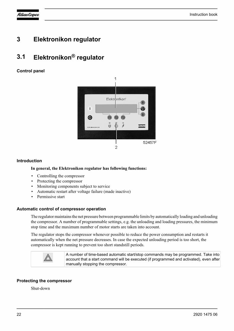
Control panel
Introduction
In general, the Elektronikon regulator has following functions:
• Controlling the compressor• Protecting the compressor• Monitoring components subject to service• Automatic restart after voltage failure (made inactive)• Permissive start
Automatic control of compressor operation
The regulator maintains the net pressure between programmable limits by automatically loading and unloadingthe compressor. A number of programmable settings, e.g. the unloading and loading pressures, the minimumstop time and the maximum number of motor starts are taken into account.
The regulator stops the compressor whenever possible to reduce the power consumption and restarts itautomatically when the net pressure decreases. In case the expected unloading period is too short, thecompressor is kept running to prevent too short standstill periods.
A number of time-based automatic start/stop commands may be programmed. Take intoaccount that a start command will be executed (if programmed and activated), even aftermanually stopping the compressor.
Protecting the compressor
Shut-down
Instruction book
22 2920 1475 06

Several sensors are provided on the compressor. If one of these measurements exceeds the programmed shut-down level, the compressor will be stopped. This will be indicated on display (1) and general alarm LED (2)will blink.
Remedy the trouble and reset the message. See also the Status data menu.
Before remedying, consult the Safety precautions.
Shut-down warning
A shut-down warning level is a programmable level below the shut-down level.
If one of the measurements exceeds the programmed shut-down warning level, a message will appear ondisplay (1) and general alarm LED (2) will light up, to warn the operator that the shut-down warning level isexceeded.
The message disappears as soon as the warning condition disappears.
Service warning
A number of service operations are grouped (called Level A, B, C, ...). Each level has a programmed timeinterval. If a time interval is exceeded, a message will appear on display (1) to warn the operator to carry outthe service actions belonging to that level.
Automatic restart after voltage failure
The regulator has a built-in function to automatically restart the compressor if the voltage is restored aftervoltage failure. For compressors leaving the factory, this function is made inactive. If desired, the functioncan be activated. Consult the Atlas Copco Customer Centre.
If activated and provided the regulator was in the automatic operation mode, thecompressor will automatically restart if the supply voltage to the module is restored withina programmed time period.The power recovery time (the period within which the voltage must be restored to have anautomatic restart) can be set between 1 and 3600 seconds or to “Infinite”. If the powerrecovery time is set to “Infinite”, the compressor will always restart after a voltage failure,no matter how long it takes to restore the voltage. A restart delay can also be programmed,allowing e.g. two compressors to be restarted one after the other.
Permissive start
After a start command (either automatic start by the electronic regulator or manual start), the permissive startfunction is operative: if the oil injection pressure at the compressor element exceeds the programmed level,the compressor will not start (indicated as “Start failure”).
Instruction book
2920 1475 06 23
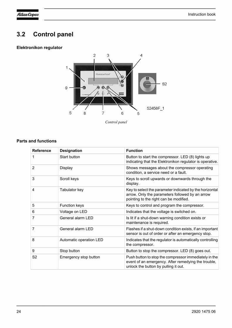
3.2 Control panel
Elektronikon regulator
Control panel
Parts and functions
Reference Designation Function1 Start button Button to start the compressor. LED (8) lights up
indicating that the Elektronikon regulator is operative.2 Display Shows messages about the compressor operating
condition, a service need or a fault.3 Scroll keys Keys to scroll upwards or downwards through the
display.4 Tabulator key Key to select the parameter indicated by the horizontal
arrow. Only the parameters followed by an arrowpointing to the right can be modified.
5 Function keys Keys to control and program the compressor.6 Voltage on LED Indicates that the voltage is switched on.7 General alarm LED Is lit if a shut-down warning condition exists or
maintenance is required.7 General alarm LED Flashes if a shut-down condition exists, if an important
sensor is out of order or after an emergency stop.8 Automatic operation LED Indicates that the regulator is automatically controlling
the compressor.9 Stop button Button to stop the compressor. LED (8) goes out.S2 Emergency stop button Push button to stop the compressor immediately in the
event of an emergency. After remedying the trouble,unlock the button by pulling it out.
Instruction book
24 2920 1475 06
3.3 Function keys
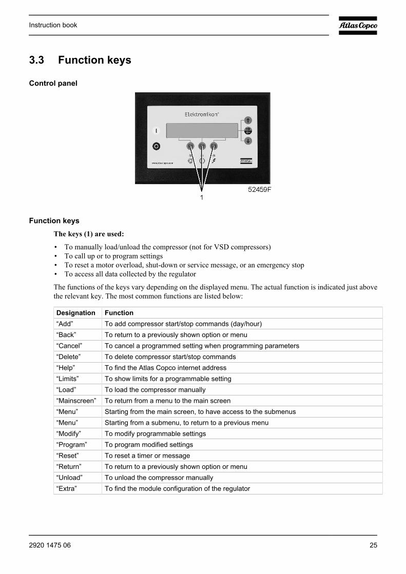
Control panel
Function keys
The keys (1) are used:
• To manually load/unload the compressor (not for VSD compressors)• To call up or to program settings• To reset a motor overload, shut-down or service message, or an emergency stop• To access all data collected by the regulator
The functions of the keys vary depending on the displayed menu. The actual function is indicated just abovethe relevant key. The most common functions are listed below:
Designation Function“Add” To add compressor start/stop commands (day/hour)“Back” To return to a previously shown option or menu“Cancel” To cancel a programmed setting when programming parameters“Delete” To delete compressor start/stop commands“Help” To find the Atlas Copco internet address“Limits” To show limits for a programmable setting“Load” To load the compressor manually“Mainscreen” To return from a menu to the main screen“Menu” Starting from the main screen, to have access to the submenus“Menu” Starting from a submenu, to return to a previous menu“Modify” To modify programmable settings“Program” To program modified settings“Reset” To reset a timer or message“Return” To return to a previously shown option or menu“Unload” To unload the compressor manually“Extra” To find the module configuration of the regulator
Instruction book
2920 1475 06 25
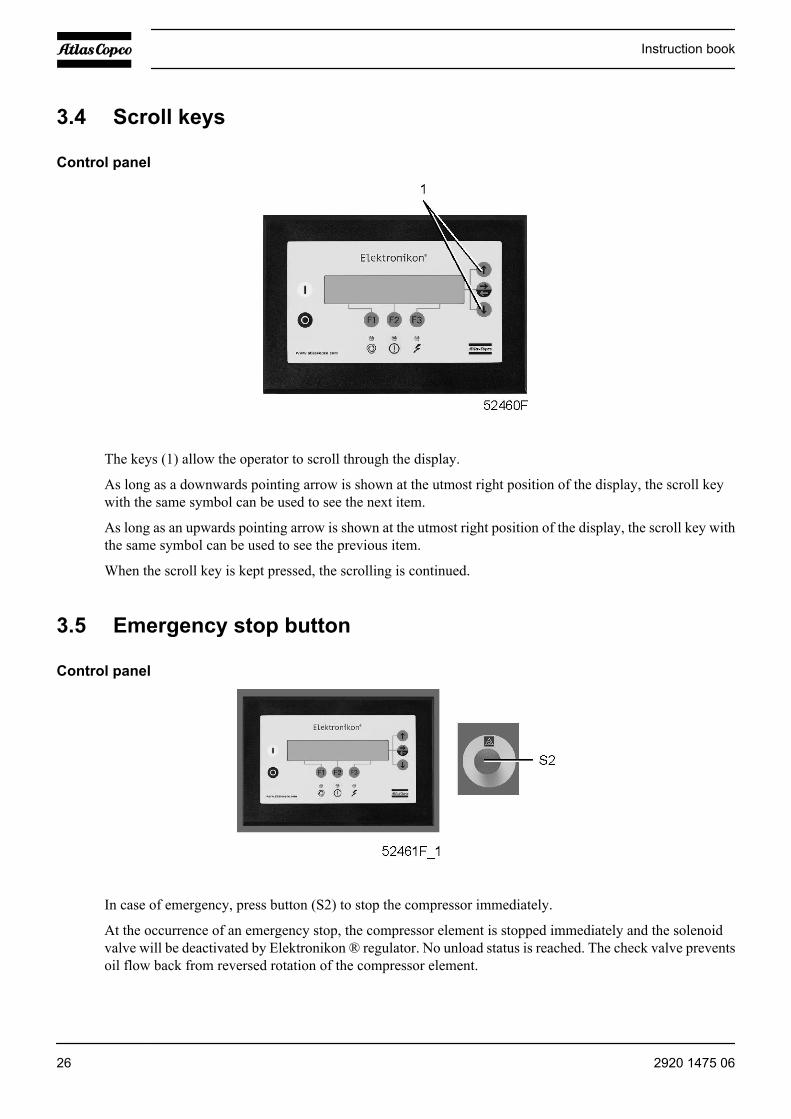
3.4 Scroll keys
Control panel
The keys (1) allow the operator to scroll through the display.
As long as a downwards pointing arrow is shown at the utmost right position of the display, the scroll keywith the same symbol can be used to see the next item.
As long as an upwards pointing arrow is shown at the utmost right position of the display, the scroll key withthe same symbol can be used to see the previous item.
When the scroll key is kept pressed, the scrolling is continued.
3.5 Emergency stop button
Control panel
In case of emergency, press button (S2) to stop the compressor immediately.
At the occurrence of an emergency stop, the compressor element is stopped immediately and the solenoidvalve will be deactivated by Elektronikon ® regulator. No unload status is reached. The check valve preventsoil flow back from reversed rotation of the compressor element.
Instruction book
26 2920 1475 06
Before starting any maintenance or repairs, wait until the compressor hasstopped and open the isolating switch (customer's installation) to switch off thevoltage to the compressor.Close the air outlet valve and open the manual condensate drain valves todepressurize the air system.Apply all relevant Safety precautions.
3.6 Control programs
Function
In order to facilitate programming and controlling, menu-driven control programs have been implemented inthe regulator.
Instruction book
2920 1475 06 27
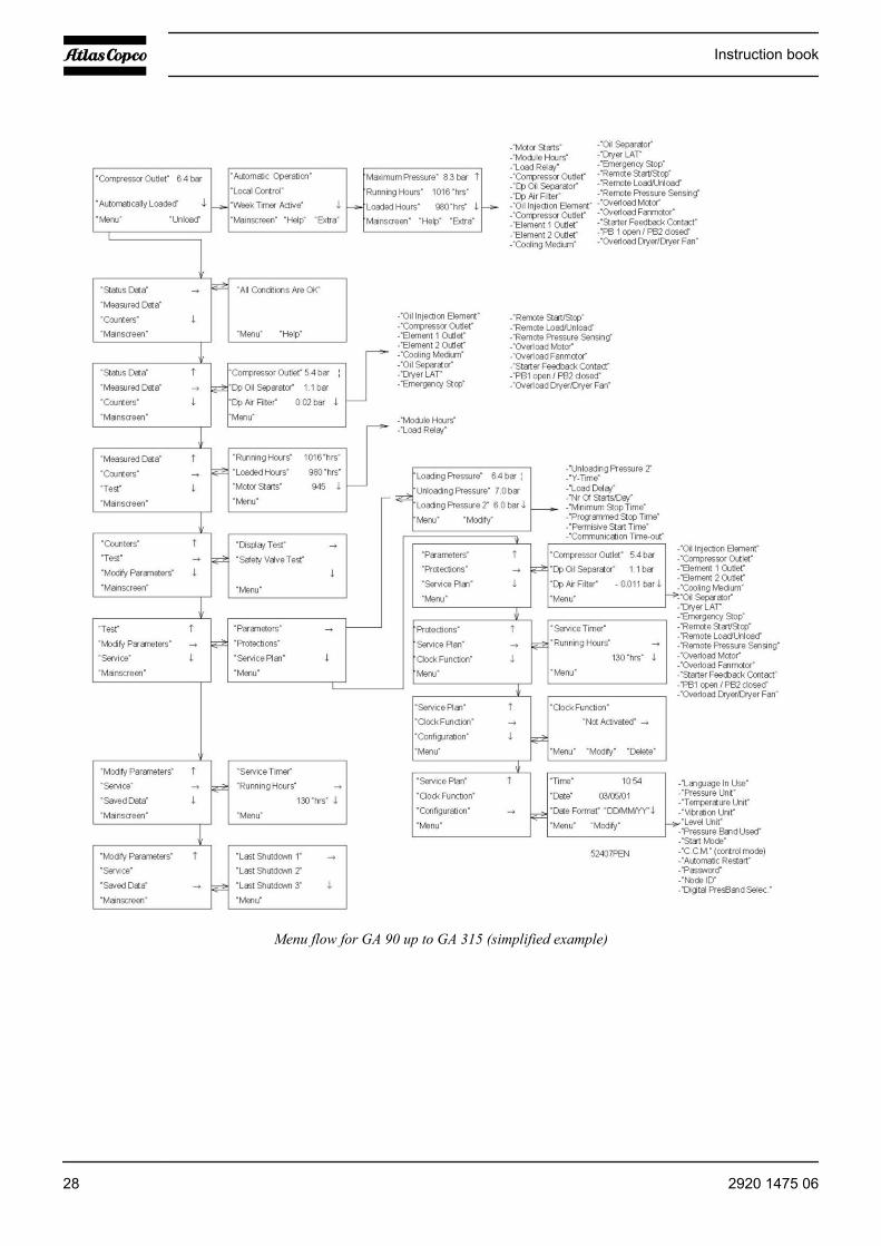
Menu flow for GA 90 up to GA 315 (simplified example)
Instruction book
28 2920 1475 06

Menu flow for GA 90 W up to GA 315 W (simplified example)
Program FunctionMain screen Shows in brief the operational status of the compressor. Is the gateway to all
functions.“Status Data” Calls up the status of the compressor protection functions (shut-down, shut-down
warning and service warning). Resets a shut-down, motor overload and servicecondition.
“Measured Data” Calls up the data currently measured and the status of a number of inputs.
Instruction book
2920 1475 06 29
Program Function“Counters” Calls up:
• running hours• regulator (module) hours• number of motor starts
“Test” Display test.“Modify Parameters” Modifying the settings for:
• Parameters (e.g. loading and unloading pressures)• Protections (e.g. temperature shut-down level)• Service plans (timers for service plans)• Clock functions (automatic compressor start/stop/pressure band commands)• Configuration (time, date, display language,...)
“Service” Calls up service plans and resets the timers after carrying out the service actions ina service plan.
“Saved Data" Calls up the saved data: last shut-down, last emergency stop data.“Unload”/”Load” Loads and unloads the compressor manually.
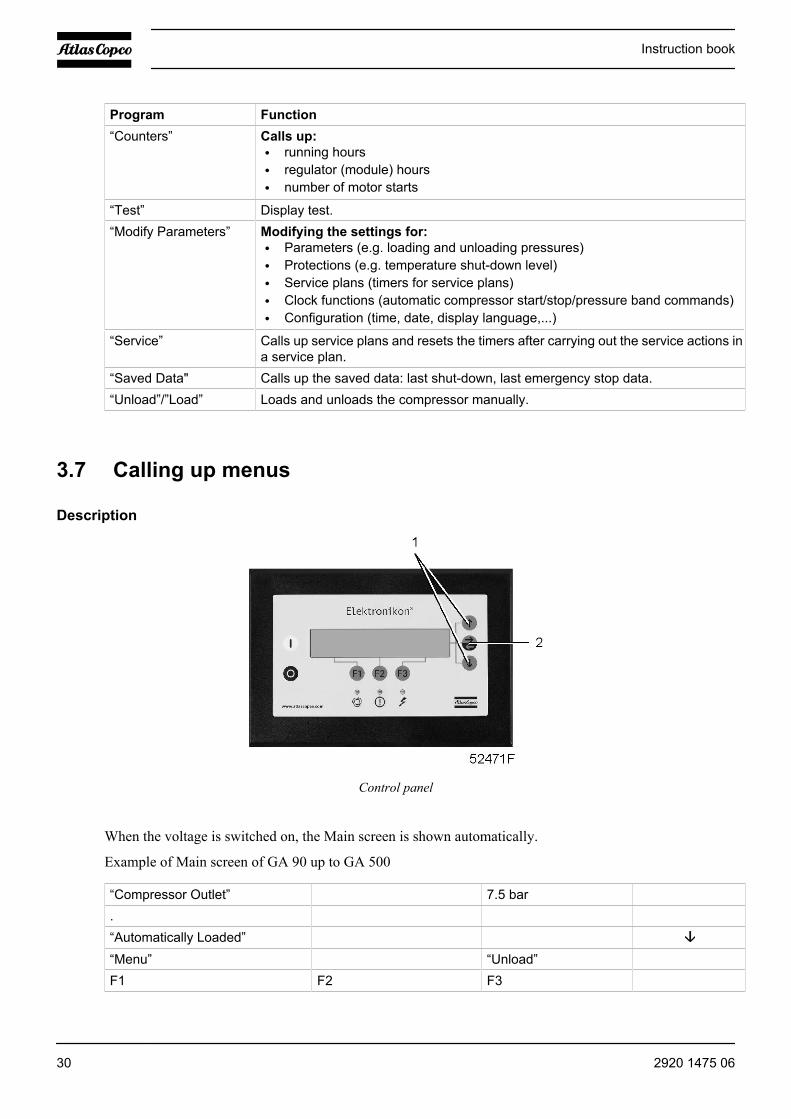
3.7 Calling up menus
Description
Control panel
When the voltage is switched on, the Main screen is shown automatically.
Example of Main screen of GA 90 up to GA 500
“Compressor Outlet” 7.5 bar.“Automatically Loaded”“Menu” “Unload”F1 F2 F3
Instruction book
30 2920 1475 06

After pressing the “Menu” (F1) key, the option “Status Data” will be followed by a horizontal arrow:
• Either press the tabulator key (2) to select this menu,• or use the arrow down key (1) until the desired submenu is followed by a horizontal arrow and then press
the tabulator key (2) to select this menu.
The arrow down key (1) can be used for a quick look at the actual compressor status.
3.8 Main screen menu
Function
Control panel
The Main screen menu shows the status of the compressor operation and is the gateway to all functionsimplemented in the regulator.
Procedure
The Main screen is shown automatically when the voltage is switched on.
If the function or arrow keys (1, 2 and 3) are not used for some minutes, the regulator will automatically returnto the Main screen.
Whenever displayed on a submenu screen, press the “Mainscreen” (F1) key to return to the Main screen.
Example of Main screen of GA 90 up to GA 500
“Compressor Outlet” 7.5 bar.“Automatically Loaded”“Menu” “Unload”F1 F2 F3
The display indicates:
• The name of the sensor and its actual reading
Instruction book
2920 1475 06 31
• Messages regarding the compressor operating condition• Just above the function keys (3), the actual functions of these keys
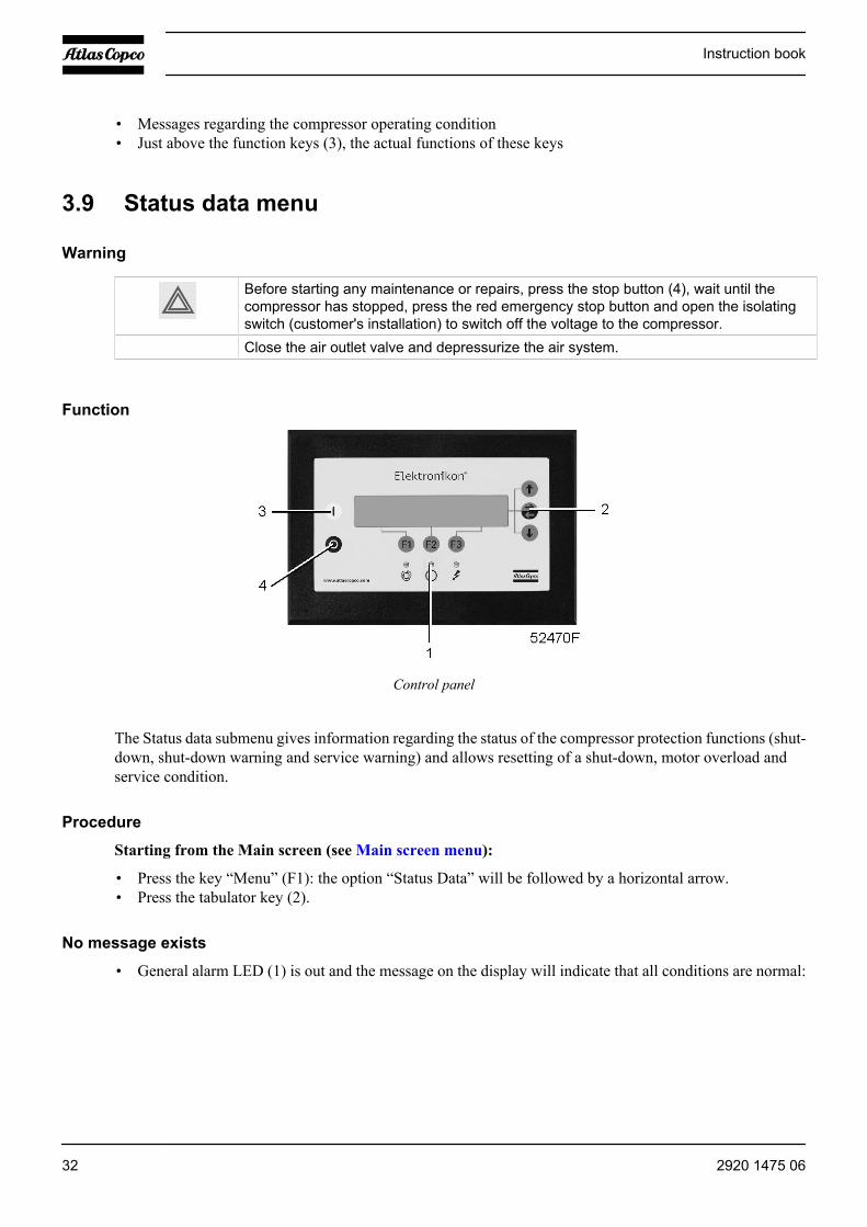
3.9 Status data menu
Warning
Before starting any maintenance or repairs, press the stop button (4), wait until thecompressor has stopped, press the red emergency stop button and open the isolatingswitch (customer's installation) to switch off the voltage to the compressor.
Close the air outlet valve and depressurize the air system.
Function
Control panel
The Status data submenu gives information regarding the status of the compressor protection functions (shut-down, shut-down warning and service warning) and allows resetting of a shut-down, motor overload andservice condition.
Procedure
Starting from the Main screen (see Main screen menu):
• Press the key “Menu” (F1): the option “Status Data” will be followed by a horizontal arrow.• Press the tabulator key (2).
No message exists
• General alarm LED (1) is out and the message on the display will indicate that all conditions are normal:
Instruction book
32 2920 1475 06
“All Conditions Are OK”..“Menu” “Help”F1 F2 F3
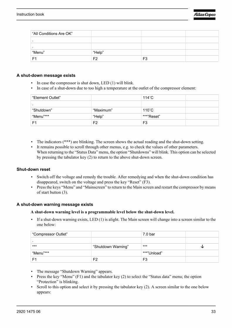
A shut-down message exists
• In case the compressor is shut down, LED (1) will blink.• In case of a shut-down due to too high a temperature at the outlet of the compressor element:
“Element Outlet” 114˚C. “Shutdown” “Maximum” 110˚C“Menu”*** “Help” ***”Reset”F1 F2 F3
• The indicators (***) are blinking. The screen shows the actual reading and the shut-down setting.• It remains possible to scroll through other menus, e.g. to check the values of other parameters.
When returning to the “Status Data” menu, the option “Shutdowns” will blink. This option can be selectedby pressing the tabulator key (2) to return to the above shut-down screen.
Shut-down reset
• Switch off the voltage and remedy the trouble. After remedying and when the shut-down condition hasdisappeared, switch on the voltage and press the key “Reset” (F3).
• Press the keys “Menu” and “Mainscreen” to return to the Main screen and restart the compressor by meansof start button (3).
A shut-down warning message exists
A shut-down warning level is a programmable level below the shut-down level.
• If a shut-down warning exists, LED (1) is alight. The Main screen will change into a screen similar to theone below:
“Compressor Outlet” 7.0 bar.*** “Shutdown Warning” ***“Menu”*** ***”Unload”F1 F2 F3
• The message “Shutdown Warning” appears.• Press the key “Menu” (F1) and the tabulator key (2) to select the “Status data” menu; the option
“Protection” is blinking.• Scroll to this option and select it by pressing the tabulator key (2). A screen similar to the one below
appears:
Instruction book
2920 1475 06 33
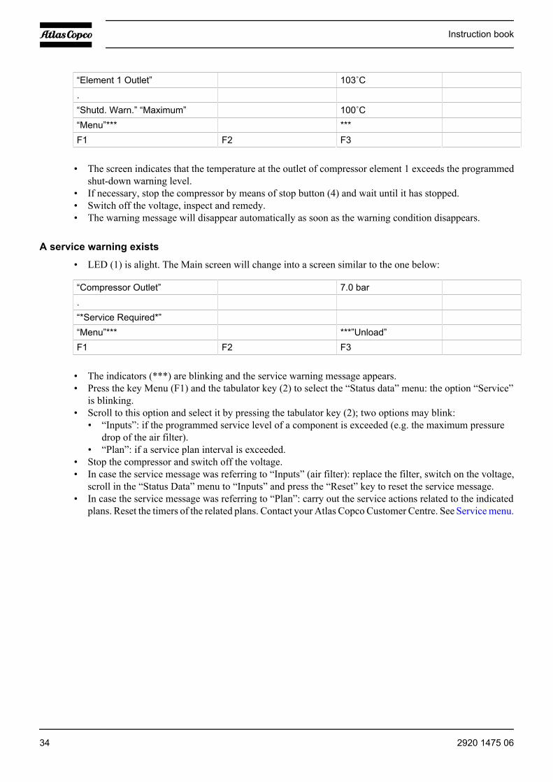
“Element 1 Outlet” 103˚C.“Shutd. Warn.” “Maximum” 100˚C“Menu”*** ***F1 F2 F3
• The screen indicates that the temperature at the outlet of compressor element 1 exceeds the programmedshut-down warning level.
• If necessary, stop the compressor by means of stop button (4) and wait until it has stopped.• Switch off the voltage, inspect and remedy.• The warning message will disappear automatically as soon as the warning condition disappears.
A service warning exists
• LED (1) is alight. The Main screen will change into a screen similar to the one below:
“Compressor Outlet” 7.0 bar.“*Service Required*” “Menu”*** ***”Unload”F1 F2 F3
• The indicators (***) are blinking and the service warning message appears.• Press the key Menu (F1) and the tabulator key (2) to select the “Status data” menu: the option “Service”
is blinking.• Scroll to this option and select it by pressing the tabulator key (2); two options may blink:
• “Inputs”: if the programmed service level of a component is exceeded (e.g. the maximum pressuredrop of the air filter).
• “Plan”: if a service plan interval is exceeded.• Stop the compressor and switch off the voltage.• In case the service message was referring to “Inputs” (air filter): replace the filter, switch on the voltage,
scroll in the “Status Data” menu to “Inputs” and press the “Reset” key to reset the service message.• In case the service message was referring to “Plan”: carry out the service actions related to the indicated
plans. Reset the timers of the related plans. Contact your Atlas Copco Customer Centre. See Service menu.
Instruction book
34 2920 1475 06
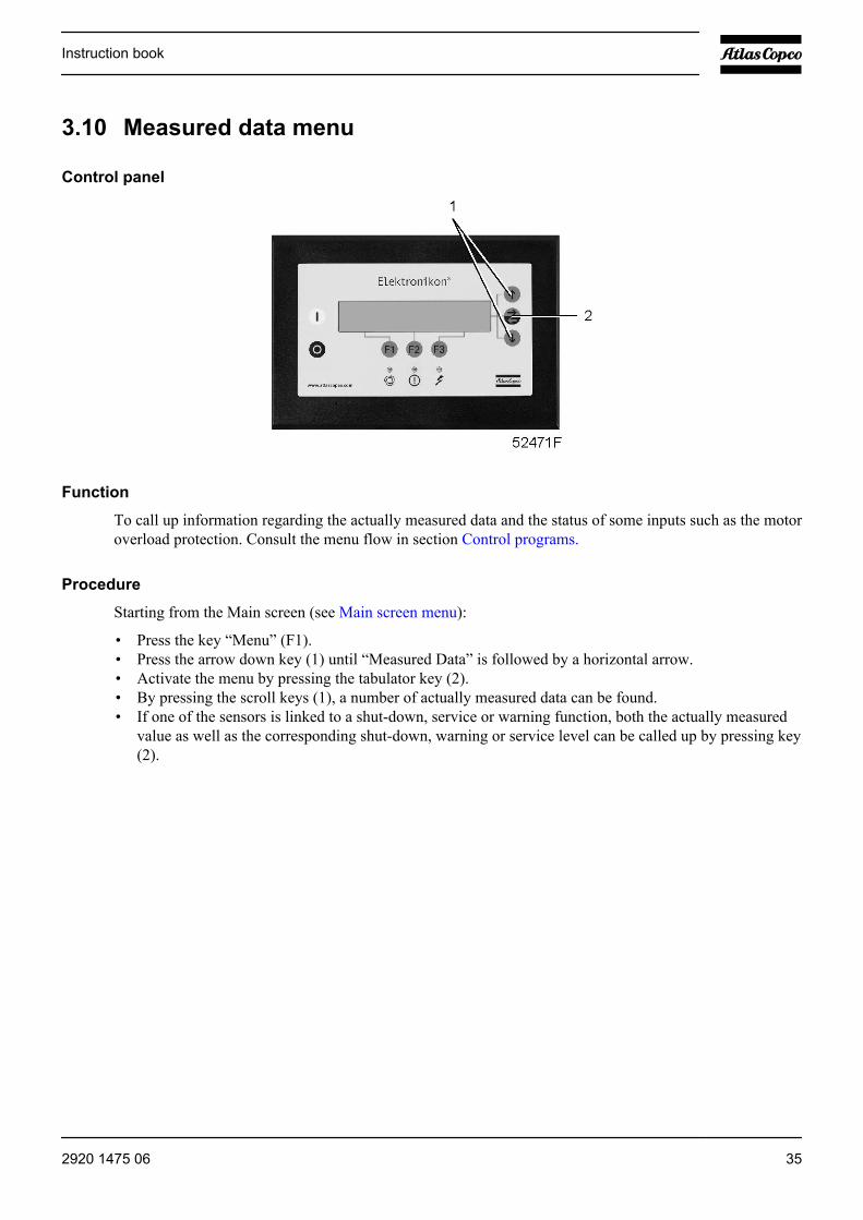
3.10 Measured data menu
Control panel
Function
To call up information regarding the actually measured data and the status of some inputs such as the motoroverload protection. Consult the menu flow in section Control programs.
Procedure
Starting from the Main screen (see Main screen menu):
• Press the key “Menu” (F1).• Press the arrow down key (1) until “Measured Data” is followed by a horizontal arrow.• Activate the menu by pressing the tabulator key (2).• By pressing the scroll keys (1), a number of actually measured data can be found.• If one of the sensors is linked to a shut-down, service or warning function, both the actually measured
value as well as the corresponding shut-down, warning or service level can be called up by pressing key(2).
Instruction book
2920 1475 06 35

3.11 Counters menu
Control panel
Function
To call up:
• The running hours• The loaded hours• The number of motor starts• The number of hours the regulator (module) has been under tension• The number of load cycles
Procedure
Starting from the Main screen (see Main screen menu):
• Press the key “Menu” (F1).• Press the arrow down key (1) until “Counters” is followed by a horizontal arrow.• Press the tabulator key (2) to activate the menu.• By pressing the arrow key (1), the above-mentioned data can be found.
Example of a Counters screen
.“Running Hours” 2455 “hrs”“Loaded Hours” 1973 “hrs”“Motor Starts” 945“Menu”F1 F2 F3
Instruction book
36 2920 1475 06

3.12 Test menu
Control panel
Function
To carry out a display test, i.e. to check whether the display and LEDs are still intact.
Procedure
• Starting from the Main screen (see Main screen menu), press the “Menu” (F1) key.• Press arrow down key (1) until “Test” is followed by a horizontal arrow.• Activate the menu by pressing the key (2).
To perform a display test:
• If necessary, scroll through the menu until “Display Test” is followed by a horizontal arrow.• Press the key (2).• During testing, the regulator will generate a series of patterns on the display which enable the operator to
check that each pixel still functions normally; the LEDs are lit at the same time.• Press the “Menu” key (F1) to return to the submenu.
3.13 Modify parameters menu
Function
To modify a number of programmable settings:
• Parameters (see section Modifying parameters).• Protections (see section Modifying protections).• Service plan settings (see section Modifying service plan settings).• Clock function settings (see section Modifying clock function settings).• Configuration settings (see section Modifying configuration settings).
Instruction book
2920 1475 06 37

3.14 Modifying parameters
Control panel
Function
To modify a number of parameters. Consult the menu flow in section Control programs.
Procedure
Starting from the Main screen (see Main screen menu):
• Press the key “Menu” (F1).• Press the arrow down key (1) until “Modify Parameters” is followed by a horizontal arrow.• Activate the menu by pressing the tabulator key (2).• The first item “Parameters” will be followed by a horizontal arrow.• Press the tabulator key (2): the first items and their settings will appear.• Press the arrow down key (1) until the parameter to be modified is followed by a horizontal arrow.
Modifying the loading pressure setpoint
If desired, the operator can program two pressure bands (Loading pressure/Unloading pressure andLoading pressure 2/Unloading pressure 2).
• Consult the section Procedure to select “Loading Pressure”.• The screen shows the current setting. To modify this setting, press the key “Modify” (F2); the setting will
blink.• The key “Limits” (F2) can be used to find out the limitations for the parameter.• Use the scroll keys (1) to change the setting.• Press the key ”Program” (F1) to program the new value or the key “Cancel” (F3) to cancel the modification
operation.• The procedure to modify other parameters pressure is similar.
The regulator will not accept new values beyond the limitations. Press the key “Limits” to checkthe limitations for the parameter. Consult Programmable settings for the most importantsettings.
Instruction book
38 2920 1475 06
3.15 Modifying protection settings
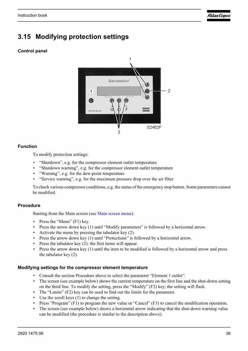
Control panel
Function
To modify protection settings:
• “Shutdown”, e.g. for the compressor element outlet temperature• “Shutdown warning”, e.g. for the compressor element outlet temperature• “Warning”, e.g. for the dew-point temperature• “Service warning”, e.g. for the maximum pressure drop over the air filter
To check various compressor conditions, e.g. the status of the emergency stop button. Some parameters cannotbe modified.
Procedure
Starting from the Main screen (see Main screen menu):
• Press the “Menu” (F1) key.• Press the arrow down key (1) until “Modify parameters” is followed by a horizontal arrow.• Activate the menu by pressing the tabulator key (2).• Press the arrow down key (1) until “Protections” is followed by a horizontal arrow.• Press the tabulator key (2): the first items will appear.• Press the arrow down key (1) until the item to be modified is followed by a horizontal arrow and press
the tabulator key (2).
Modifying settings for the compressor element temperature
• Consult the section Procedure above to select the parameter “Element 1 outlet”.• The screen (see example below) shows the current temperature on the first line and the shut-down setting
on the third line. To modify the setting, press the “Modify” (F2) key; the setting will flash.• The “Limits” (F2) key can be used to find out the limits for the parameter.• Use the scroll keys (1) to change the setting.• Press ”Program” (F1) to program the new value or “Cancel” (F3) to cancel the modification operation.• The screen (see example below) shows a horizontal arrow indicating that the shut-down warning value
can be modified (the procedure is similar to the description above).
Instruction book
2920 1475 06 39
• The procedure to modify other items is similar. For some settings, a delay can be programmed.
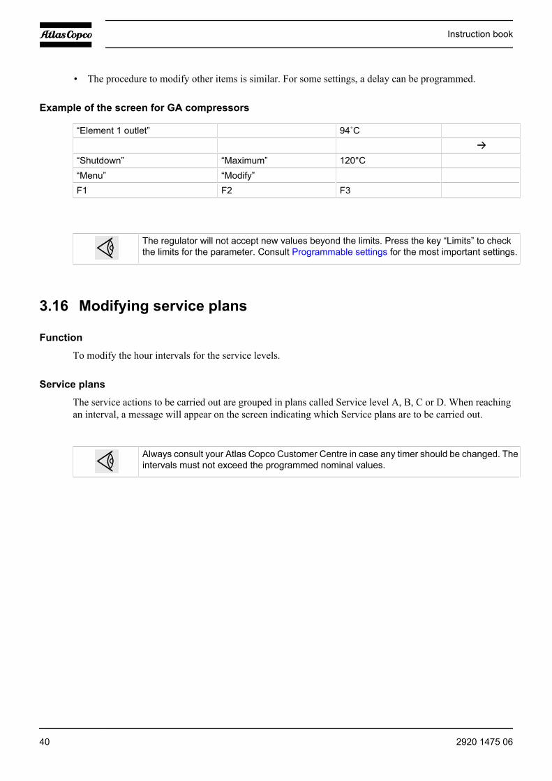
Example of the screen for GA compressors
“Element 1 outlet” 94˚C
“Shutdown” “Maximum” 120°C“Menu” “Modify”F1 F2 F3
The regulator will not accept new values beyond the limits. Press the key “Limits” to checkthe limits for the parameter. Consult Programmable settings for the most important settings.
3.16 Modifying service plans
Function
To modify the hour intervals for the service levels.
Service plans
The service actions to be carried out are grouped in plans called Service level A, B, C or D. When reachingan interval, a message will appear on the screen indicating which Service plans are to be carried out.
Always consult your Atlas Copco Customer Centre in case any timer should be changed. Theintervals must not exceed the programmed nominal values.
Instruction book
40 2920 1475 06

3.17 Programming clock function
Control panel
Function
To program:
• Time-based start/stop commands for the compressor• Time-based change-over commands for the net pressure band
Programming start, stop and pressure band commands
In this example, the compressor will be programmed as follows:
• On Monday at 06:15 starting in pressure band 1• On Friday at 18:00 changing over to pressure band 2• On Saturday at 18:00 stopping
Starting from the Main screen (see Main screen menu):
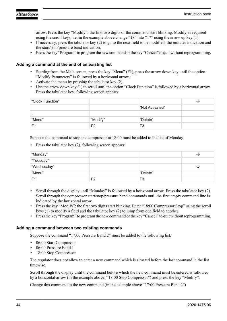
• Press the key “Menu” (F1).• Press the arrow down key (1) until “Modify Parameters” is followed by a horizontal arrow.• Activate the menu by pressing tabulator key (2).• Use the arrow down key (1) to scroll until the option “Clock Function” is followed by a horizontal arrow.• Activate the menu by pressing tabulator key (2); following screen appears:
“Clock Function”“Not Activated”
.“Menu” “Modify” “Delete”F1 F2 F3
• Press the tabulator key (2), following screen appears:
Instruction book
2920 1475 06 41
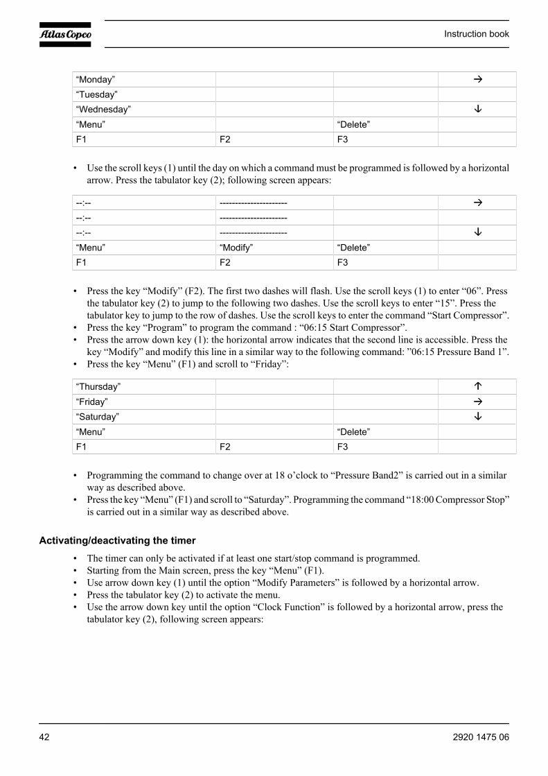
“Monday”“Tuesday”“Wednesday”“Menu” “Delete”F1 F2 F3
• Use the scroll keys (1) until the day on which a command must be programmed is followed by a horizontalarrow. Press the tabulator key (2); following screen appears:
--:-- ------------------------:-- ------------------------:-- ----------------------“Menu” “Modify” “Delete”F1 F2 F3
• Press the key “Modify” (F2). The first two dashes will flash. Use the scroll keys (1) to enter “06”. Pressthe tabulator key (2) to jump to the following two dashes. Use the scroll keys to enter “15”. Press thetabulator key to jump to the row of dashes. Use the scroll keys to enter the command “Start Compressor”.
• Press the key “Program” to program the command : “06:15 Start Compressor”.• Press the arrow down key (1): the horizontal arrow indicates that the second line is accessible. Press the
key “Modify” and modify this line in a similar way to the following command: ”06:15 Pressure Band 1”.• Press the key “Menu” (F1) and scroll to “Friday”:
“Thursday”“Friday”“Saturday”“Menu” “Delete”F1 F2 F3
• Programming the command to change over at 18 o’clock to “Pressure Band2” is carried out in a similarway as described above.
• Press the key “Menu” (F1) and scroll to “Saturday”. Programming the command “18:00 Compressor Stop”is carried out in a similar way as described above.
Activating/deactivating the timer
• The timer can only be activated if at least one start/stop command is programmed.• Starting from the Main screen, press the key “Menu” (F1).• Use arrow down key (1) until the option “Modify Parameters” is followed by a horizontal arrow.• Press the tabulator key (2) to activate the menu.• Use the arrow down key until the option “Clock Function” is followed by a horizontal arrow, press the
tabulator key (2), following screen appears:
Instruction book
42 2920 1475 06
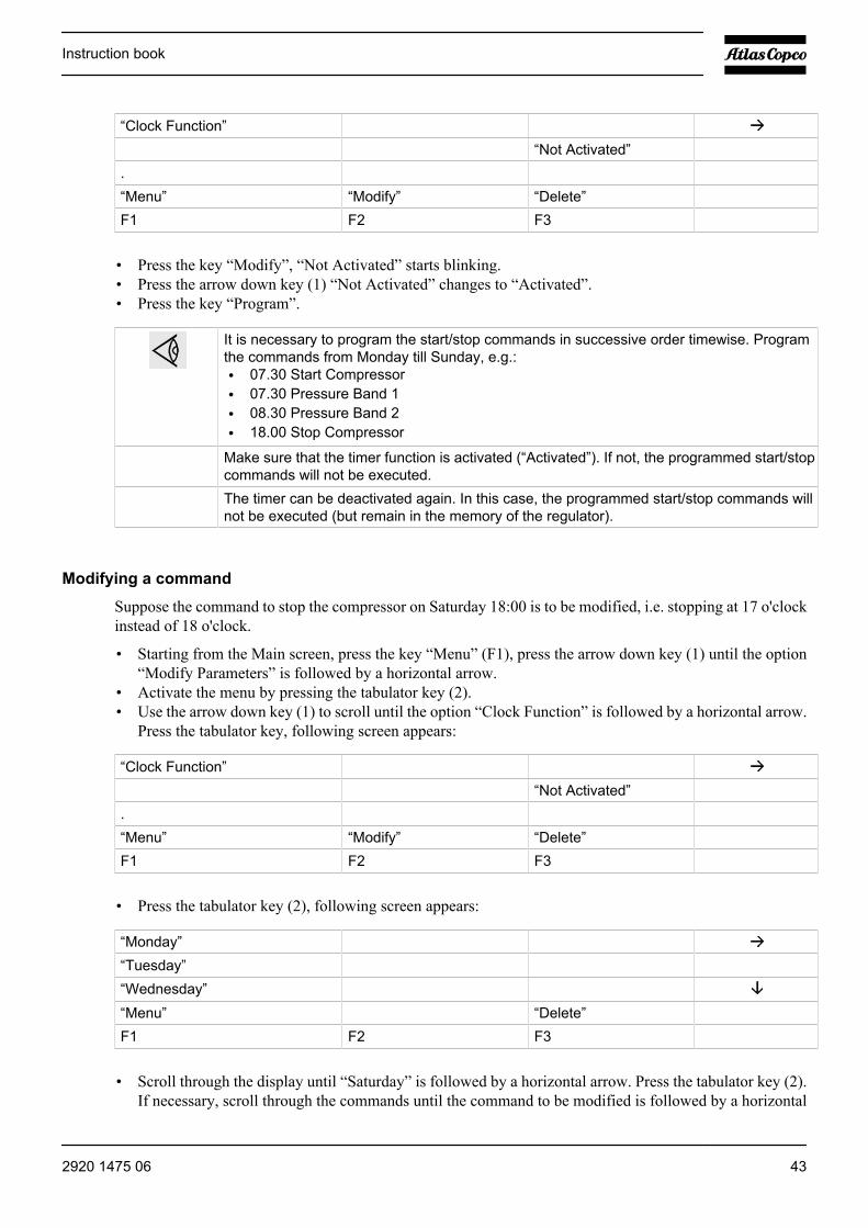
“Clock Function”“Not Activated”
.“Menu” “Modify” “Delete”F1 F2 F3
• Press the key “Modify”, “Not Activated” starts blinking.• Press the arrow down key (1) “Not Activated” changes to “Activated”.• Press the key “Program”.
It is necessary to program the start/stop commands in successive order timewise. Programthe commands from Monday till Sunday, e.g.:• 07.30 Start Compressor• 07.30 Pressure Band 1• 08.30 Pressure Band 2• 18.00 Stop Compressor
Make sure that the timer function is activated (“Activated”). If not, the programmed start/stopcommands will not be executed.
The timer can be deactivated again. In this case, the programmed start/stop commands willnot be executed (but remain in the memory of the regulator).
Modifying a command
Suppose the command to stop the compressor on Saturday 18:00 is to be modified, i.e. stopping at 17 o'clockinstead of 18 o'clock.
• Starting from the Main screen, press the key “Menu” (F1), press the arrow down key (1) until the option“Modify Parameters” is followed by a horizontal arrow.
• Activate the menu by pressing the tabulator key (2).• Use the arrow down key (1) to scroll until the option “Clock Function” is followed by a horizontal arrow.
Press the tabulator key, following screen appears:
“Clock Function”“Not Activated”
.“Menu” “Modify” “Delete”F1 F2 F3
• Press the tabulator key (2), following screen appears:
“Monday”“Tuesday”“Wednesday”“Menu” “Delete”F1 F2 F3
• Scroll through the display until “Saturday” is followed by a horizontal arrow. Press the tabulator key (2).If necessary, scroll through the commands until the command to be modified is followed by a horizontal
Instruction book
2920 1475 06 43
arrow. Press the key “Modify”, the first two digits of the command start blinking. Modify as requiredusing the scroll keys, i.e. in the example above change “18” into “17” using the arrow up key (1).
• If necessary, press the tabulator key (2) to go to the next field to be modified, the minutes indication andthe start/stop/pressure band indication.
• Press the key “Program” to program the new command or the key “Cancel” to quit without reprogramming.
Adding a command at the end of an existing list
• Starting from the Main screen, press the key “Menu” (F1), press the arrow down key until the option“Modify Parameters” is followed by a horizontal arrow.
• Activate the menu by pressing the tabulator key (2).• Use the arrow down key (1) to scroll until the option “Clock Function” is followed by a horizontal arrow.
Press the tabulator key, following screen appears:
“Clock Function”“Not Activated”
.“Menu” “Modify” “Delete”F1 F2 F3
Suppose the command to stop the compressor at 18:00 must be added to the list of Monday
• Press the tabulator key (2), following screen appears:
“Monday”“Tuesday”“Wednesday”“Menu” “Delete”F1 F2 F3
• Scroll through the display until “Monday” is followed by a horizontal arrow. Press the tabulator key (2).Scroll through the compressor start/stop/pressure band commands until the first empty command line isindicated by the horizontal arrow.
• Press the key “Modify”; the first two digits start blinking. Enter “18:00 Compressor Stop” using the scrollkeys (1) to modify a field and the tabulator key (2) to jump from one field to another.
• Press the key “Program” to program the new command or the key “Cancel” to quit without reprogramming.
Adding a command between two existing commands
Suppose the command “17:00 Pressure Band 2” must be added to the following list:
• 06:00 Start Compressor• 06:00 Pressure Band 1• 18:00 Stop Compressor
The regulator does not allow to enter a new command which is situated before the last command in the listtimewise.
Scroll through the display until the command before which the new command must be entered is followedby a horizontal arrow (in the example above: “18:00 Stop Compressor”) and press the key “Modify”.
Change this command to the new command (in the example above “17:00 Pressure Band 2”)
Instruction book
44 2920 1475 06
Press the arrow down key and add the last command of the list (in the example above “18:00 Stop Compressor”and press the key “Program”.
Deleting a command
• Starting from the Main screen, press the key “Menu” (F1), press the arrow down key until the option“Modify Parameters” is followed by a horizontal arrow.
• Activate the menu by pressing the tabulator key (2).• Use the scroll keys (1) to scroll until the option “Clock Function” is followed by a horizontal arrow. Press
the tabulator key, following screen appears:
“Clock Function”“Not Activated”
.“Menu” “Modify” “Delete”F1 F2 F3
Deleting all commands
• Press the key “Delete” in the screen above. A question to confirm the deleting operation will appear.
Deleting all commands of a specific day
• Scroll through the display until the desired day is followed by a horizontal arrow. Press the key “Delete”,a question to confirm the deleting operation will appear.
Deleting a specific command
• Scroll through the display until the command to be deleted is followed by a horizontal arrow. Press thekey “Delete”, a question to confirm the deleting operation will appear.
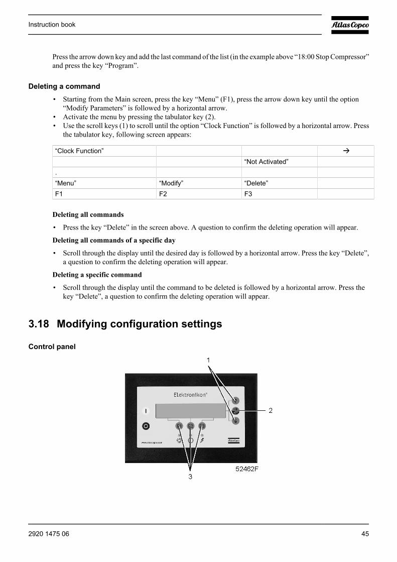
3.18 Modifying configuration settings
Control panel
Instruction book
2920 1475 06 45
Function
To modify a number of parameters. Consult the menu flow in section Control programs.
Procedure
Starting from the Main screen (see Main screen menu):
• Press the key “Menu” (F1).• Press the arrow down key (1) until “Modify Parameters” is followed by an arrow pointing to the right.• Activate the menu by pressing tabulator key (2).• Press the arrow down key (1) to scroll until “Configuration” is followed by a horizontal arrow.• Activate the menu by pressing tabulator key (2): the first item will appear. Scroll through the display until
the option to be modified is followed by a horizontal arrow. Select the option by pressing the tabulatorkey (2).
• In case of the option “Time”, the second line on the screen indicates the actual setting, e.g. “14:30”. Tomodify this setting, press the key “Modify” (F2); the first field “14” will blink.
• Use the scroll keys (1) to change the setting, then press the tabulator key (2) to go to the next field “30”.The setting of this field can now be modified using the scroll keys (1).
• Press the key ”Program” (F1) to program the new value or the key “Cancel” (F3) to cancel the modificationoperation (the original value will be retained).
• The procedure to modify other parameters is similar.
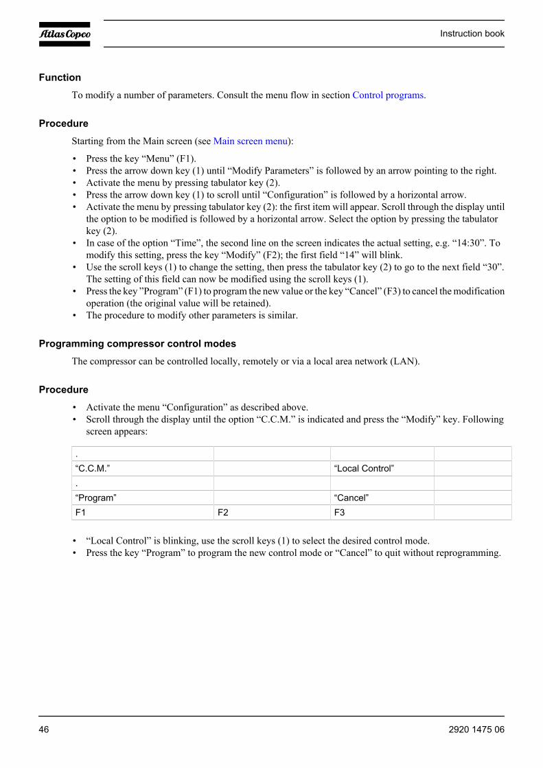
Programming compressor control modes
The compressor can be controlled locally, remotely or via a local area network (LAN).
Procedure
• Activate the menu “Configuration” as described above.• Scroll through the display until the option “C.C.M.” is indicated and press the “Modify” key. Following
screen appears:
.“C.C.M.” “Local Control”.“Program” “Cancel”F1 F2 F3
• “Local Control” is blinking, use the scroll keys (1) to select the desired control mode.• Press the key “Program” to program the new control mode or “Cancel” to quit without reprogramming.
Instruction book
46 2920 1475 06
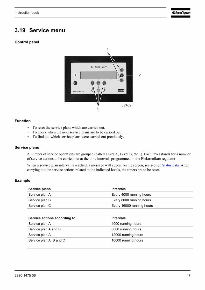
3.19 Service menu
Control panel
Function
• To reset the service plans which are carried out.• To check when the next service plans are to be carried out.• To find out which service plans were carried out previously.
Service plans
A number of service operations are grouped (called Level A, Level B, etc...). Each level stands for a numberof service actions to be carried out at the time intervals programmed in the Elektronikon regulator.
When a service plan interval is reached, a message will appear on the screen, see section Status data. Aftercarrying out the service actions related to the indicated levels, the timers are to be reset.
Example
Service plans IntervalsService plan A Every 4000 running hoursService plan B Every 8000 running hoursService plan C Every 16000 running hours
Service actions according to IntervalsService plan A 4000 running hoursService plan A and B 8000 running hoursService plan A 12000 running hoursService plan A, B and C 16000 running hours... ...
Instruction book
2920 1475 06 47
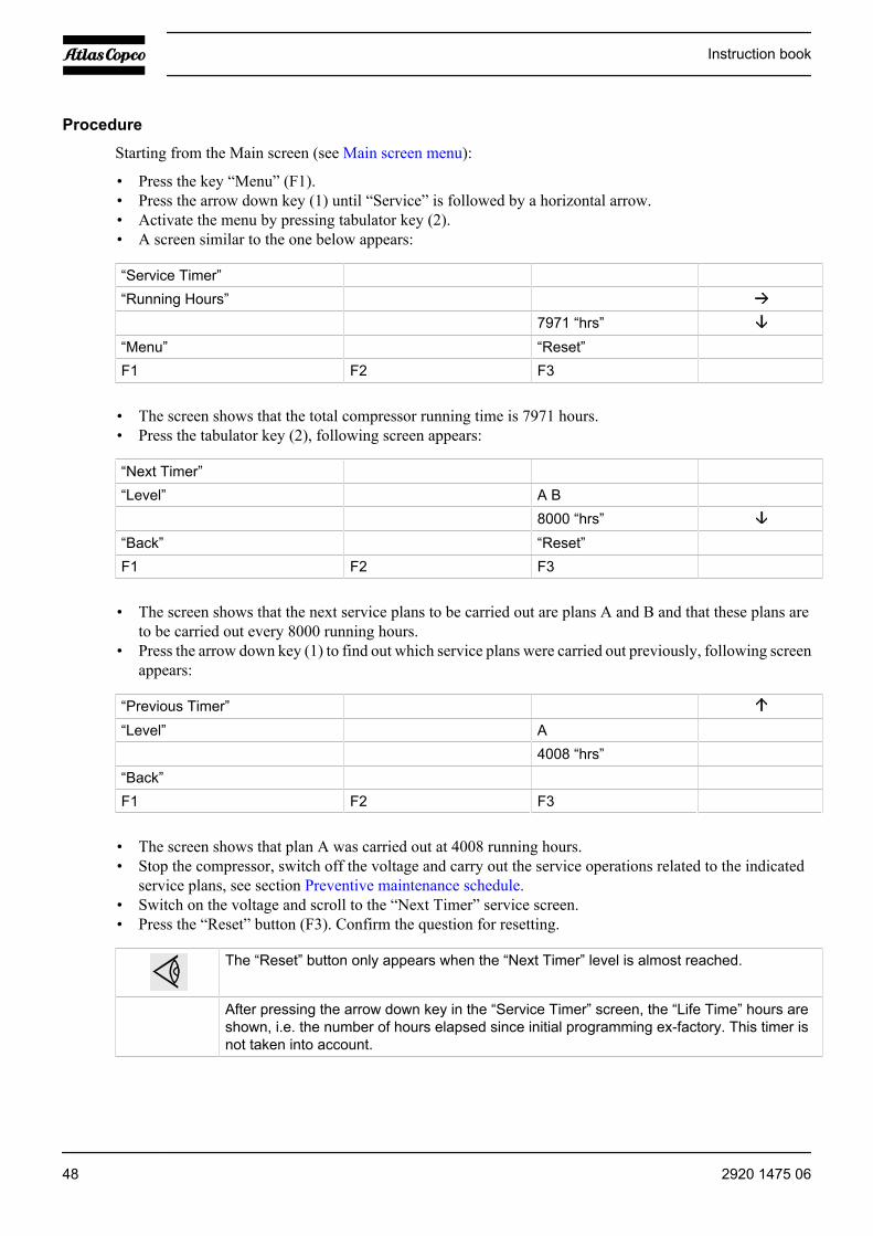
Procedure
Starting from the Main screen (see Main screen menu):
• Press the key “Menu” (F1).• Press the arrow down key (1) until “Service” is followed by a horizontal arrow.• Activate the menu by pressing tabulator key (2).• A screen similar to the one below appears:
“Service Timer”“Running Hours”
7971 “hrs”“Menu” “Reset”F1 F2 F3
• The screen shows that the total compressor running time is 7971 hours.• Press the tabulator key (2), following screen appears:
“Next Timer”“Level” A B
8000 “hrs”“Back” “Reset”F1 F2 F3
• The screen shows that the next service plans to be carried out are plans A and B and that these plans areto be carried out every 8000 running hours.
• Press the arrow down key (1) to find out which service plans were carried out previously, following screenappears:
“Previous Timer”“Level” A
4008 “hrs”“Back”F1 F2 F3
• The screen shows that plan A was carried out at 4008 running hours.• Stop the compressor, switch off the voltage and carry out the service operations related to the indicated
service plans, see section Preventive maintenance schedule.• Switch on the voltage and scroll to the “Next Timer” service screen.• Press the “Reset” button (F3). Confirm the question for resetting.
The “Reset” button only appears when the “Next Timer” level is almost reached.
After pressing the arrow down key in the “Service Timer” screen, the “Life Time” hours areshown, i.e. the number of hours elapsed since initial programming ex-factory. This timer isnot taken into account.
Instruction book
48 2920 1475 06
3.20 Saved data menu
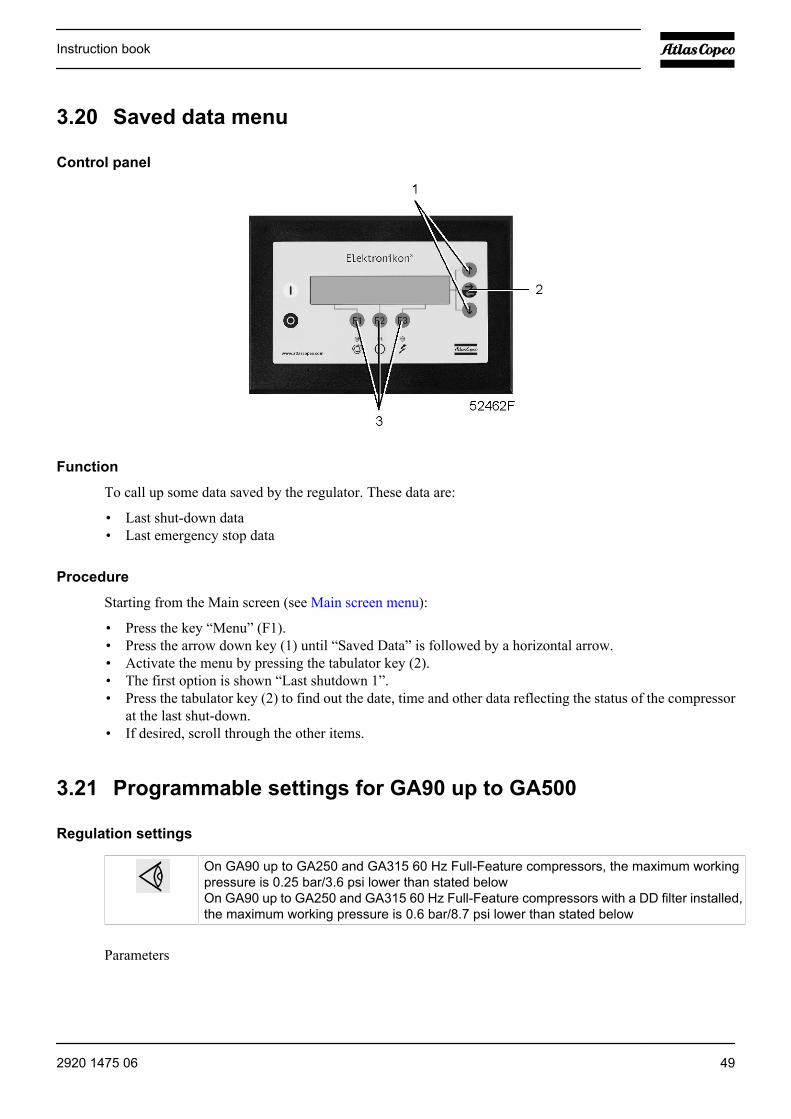
Control panel
Function
To call up some data saved by the regulator. These data are:
• Last shut-down data• Last emergency stop data
Procedure
Starting from the Main screen (see Main screen menu):
• Press the key “Menu” (F1).• Press the arrow down key (1) until “Saved Data” is followed by a horizontal arrow.• Activate the menu by pressing the tabulator key (2).• The first option is shown “Last shutdown 1”.• Press the tabulator key (2) to find out the date, time and other data reflecting the status of the compressor
at the last shut-down.• If desired, scroll through the other items.
3.21 Programmable settings for GA90 up to GA500
Regulation settings
On GA90 up to GA250 and GA315 60 Hz Full-Feature compressors, the maximum workingpressure is 0.25 bar/3.6 psi lower than stated belowOn GA90 up to GA250 and GA315 60 Hz Full-Feature compressors with a DD filter installed,the maximum working pressure is 0.6 bar/8.7 psi lower than stated below
Parameters
Instruction book
2920 1475 06 49
Minimumsetting
Factorysetting
Maximumsetting
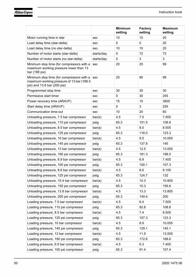
Motor running time in star sec 10 10 20Load delay time (star-delta) sec 0 0 20Load delay time (no star-delta) sec 10 10 20Number of motor starts (star-delta) starts/day 0 72 72Number of motor starts (no star-delta) starts/day 0 3 3Minimum stop time (for compressors with amaximum working pressure lower than 13bar (188 psi)
sec 20 20 99
Minimum stop time (for compressors with amaximum working pressure of 13 bar (188.5psi) and 13.8 bar (200 psi)
sec 20 90 99
Programmed stop time sec 30 30 30Permissive start timer sec 0 30 255Power recovery time (ARAVF) sec 15 15 3600Start delay time (ARAVF) sec 0 3 255Communication time-out sec 10 20 60Unloading pressure, 7.5 bar compressor bar(e) 4.5 7.0 7.505Unloading pressure, 110 psi compressor psig 65.3 101.5 108.8Unloading pressure, 8.5 bar compressor bar(e) 4.5 8.0 8.505Unloading pressure, 125 psi compressor psig 65.3 116.0 123.3Unloading pressure, 10 bar compressor bar(e) 4.5 9.5 10.005Unloading pressure, 145 psi compressor psig 65.3 137.8 145Unloading pressure, 13 bar compressor bar(e) 4.5 12.5 13.005Unloading pressure, 190 psi compressor psig 65.3 181.3 188.5Unloading pressure, 6.9 bar compressor bar(e) 4.5 6.9 7.405Unloading pressure, 100 psi compressor psig 65.3 100.1 107.3Unloading pressure, 8.6 bar compressor bar(e) 4.5 8.6 9.105Unloading pressure, 125 psi compressor psig 65.3 124.7 132Unloading pressure, 10.4 bar compressor bar(e) 4.5 10.3 10.805Unloading pressure, 150 psi compressor psig 65.3 10.3 156.6Unloading pressure, 13.8 bar compressor bar(e) 4.5 13.3 13.805Unloading pressure, 200 psi compressor psig 65.3 149.4 200Loading pressure, 7.5 bar compressor bar(e) 4.5 6.4 7.505Loading pressure, 110 psi compressor psig 65.3 92.8 108.8Loading pressure, 8.5 bar compressor bar(e) 4.5 7.4 8.505Loading pressure, 125 psi compressor psig 65.3 107.3 123.3Loading pressure, 10 bar compressor bar(e) 4.5 8.9 10.005Loading pressure, 145 psi compressor psig 65.3 129.1 145.1Loading pressure, 13 bar compressor bar(e) 4.5 11.9 13.005Loading pressure, 190 psi compressor psig 65.3 172.6 188.6Loading pressure, 6.9 bar compressor bar(e) 4.5 6.3 7.405Loading pressure, 100 psi compressor psig 65.3 91.4 107.4
Instruction book
50 2920 1475 06

Minimumsetting
Factorysetting
Maximumsetting
Loading pressure, 8.6 bar compressor bar(e) 4.5 8.0 9.105Loading pressure, 125 psi compressor psig 65.3 91.4 132.1Loading pressure, 10.4 bar compressor bar(e) 4.5 9.7 10.805Loading pressure, 150 psi compressor psig 65.3 140.7 156.7Loading pressure, 13.8 bar compressor bar(e) 4.5 12.7 13.805Loading pressure, 200 psi compressor psig 65.3 184.2 200.2
Protection settings for GA90 up to GA250 and GA315 60 Hz
Minimumsetting
Factorysetting
Maximumsetting
Compressor outlet pressure (shut-downwarning level)
bar 0 16.5 17.0
Compressor outlet pressure (shut-downwarning level)
psi 0 239.3 246.5
Compressor outlet pressure (shut-downlevel)
bar 0 17.0 17.0
Compressor outlet pressure (shut-downlevel)
psi 0 246.5 246.5
Oil injection pressure, element (startprotection)
bar 2.0 2.5 13.2
Oil injection pressure, element (startprotection)
psi 29 36.2 191.4
Compressor outlet temperature (without DDfilter) (shut-down warning level)
˚C 0 66 120
Compressor outlet temperature (without DDfilter) (shut-down warning level)
˚F 32 150.8 248
Compressor outlet temperature (without DDfilter) (shut-down level)
˚C 0 80 120
Compressor outlet temperature (without DDfilter) (shut-down level)
˚F 32 176 248
Compressor outlet temperature (with DDfilter) (shut-down warning level)
˚C 0 66 100
Compressor outlet temperature (with DDfilter) (shut-down warning level)
˚F 32 150.8 212
Compressor outlet temperature (with DDfilter) (shut-down level)
˚C 0 80 100
Compressor outlet temperature (with DDfilter) (shut-down level)
˚F 32 176 212
Compressor outlet temperature (delay atsignal)
sec 5 5 5
Compressor element outlet temperature(shut-down warning level) (without energyrecovery)
˚C 80 100 110
Instruction book
2920 1475 06 51
Minimumsetting
Factorysetting
Maximumsetting
Compressor element outlet temperature(shut-down warning level) (without energyrecovery)
˚F 176 212 228
Compressor element outlet temperature(shut-down level) (without energy recovery)
˚C 80 110 110
Compressor element outlet temperature(shut-down level)(without energy recovery)
˚F 176 230 230
Compressor element outlet temperature(shut-down warning level) (with energyrecovery)
˚C 80 114 120
Compressor element outlet temperature(shut-down warning level) (with energyrecovery)
˚F 176 237.2 248
Compressor element outlet temperature(shut-down level) (with energy recovery)
˚C 80 120 120
Compressor element outlet temperature(shut-down level) (with energy recovery)
˚F 176 248 248
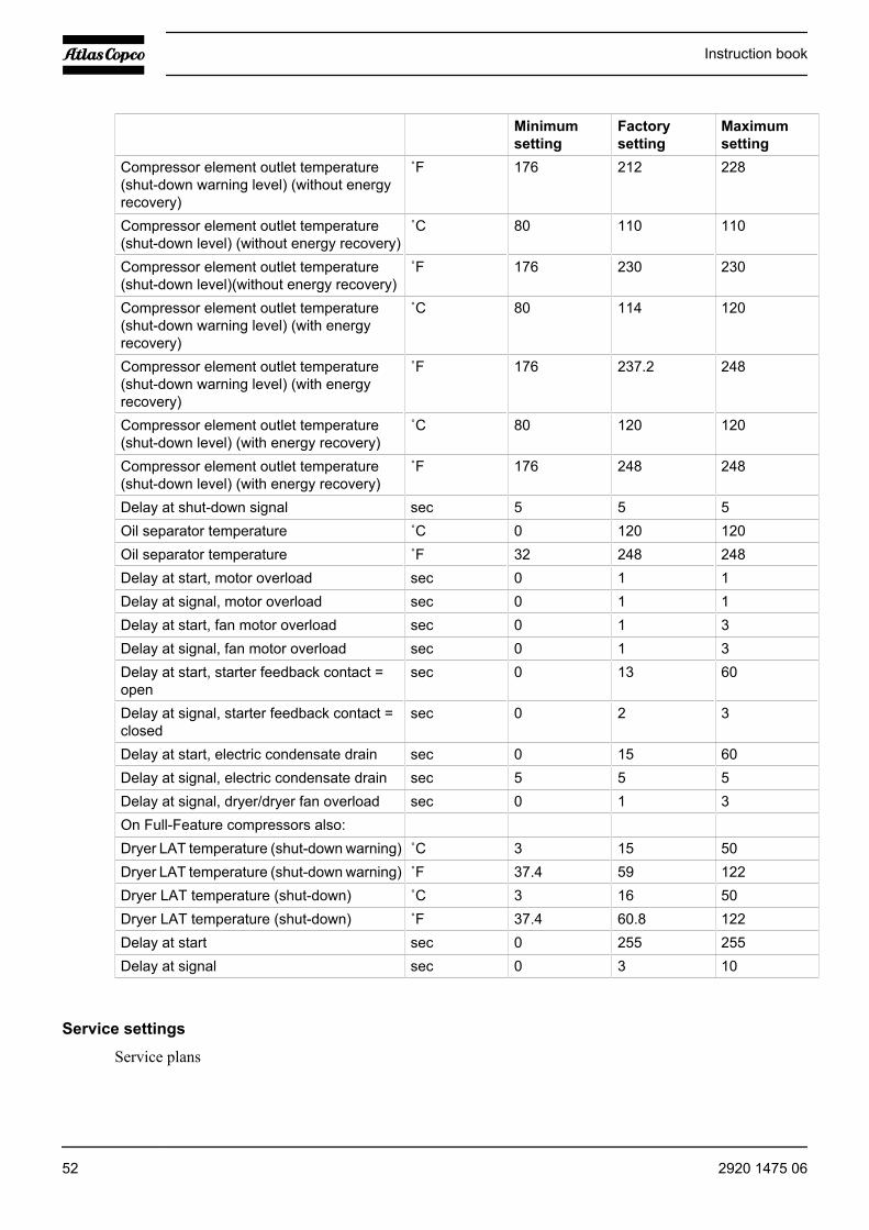
Delay at shut-down signal sec 5 5 5Oil separator temperature ˚C 0 120 120Oil separator temperature ˚F 32 248 248Delay at start, motor overload sec 0 1 1Delay at signal, motor overload sec 0 1 1Delay at start, fan motor overload sec 0 1 3Delay at signal, fan motor overload sec 0 1 3Delay at start, starter feedback contact =open
sec 0 13 60
Delay at signal, starter feedback contact =closed
sec 0 2 3
Delay at start, electric condensate drain sec 0 15 60Delay at signal, electric condensate drain sec 5 5 5Delay at signal, dryer/dryer fan overload sec 0 1 3On Full-Feature compressors also: Dryer LAT temperature (shut-down warning) ˚C 3 15 50Dryer LAT temperature (shut-down warning) ˚F 37.4 59 122Dryer LAT temperature (shut-down) ˚C 3 16 50Dryer LAT temperature (shut-down) ˚F 37.4 60.8 122Delay at start sec 0 255 255Delay at signal sec 0 3 10
Service settings
Service plans
Instruction book
52 2920 1475 06

Minimumsetting
Factorysetting
Maximumsetting
Service plan A (operating hours) hr 4000 Service plan B (operating hours) hr 8000 Service plan C (operating hours) hr 16000 Service plan D (running hours) hr 24000 Service plan I (operating hours) hr 2000
Analog inputs for GA90 up to GA250 and GA315 60 Hz
Minimumsetting
Factorysetting
Maximumsetting
Service warning level for oil separators bar 0 0.8 0.8Service warning level for oil separators psi 0 11.6 11.6Delay at signal, oil separator sec 0 60 255Service warning level for air filters bar -0.1 -0.05 -0.05Service warning level for air filters psi -1.45 -0.7 -0.7Delay at signal, air filter sec 0 60 255Service warning level for DD filter bar 0.1 0.35 0.35Service warning level for DD filter psi 1.45 5.1 5.1Delay at signal, DD filter sec 0 60 255
Terminology
Term ExplanationARAVF Automatic restart after voltage failure.See Elektronikon regulator.Compressorelement outlet
The regulator does not accept illogical settings, e.g. if the warning level is programmed at95˚C/203˚F, the minimum limit for the shut-down level changes to 96˚C/204˚F. Therecommended difference between the warning level and shut-down level is 10˚C/18˚F.
Required stopperiod/Minimumstop time
Once the compressor has automatically stopped, it will remain stopped for the minimumstop time (approx. 20 seconds), whatever the net air pressure. In automatic operation, thecompressor will not be stopped by the regulator until a standstill period of at least the sumof the minimum stop time and required stop period is expected. However, if the decreasein air net pressure should require a new start of the compressor, the regulator will start thecompressor after the minimum stop time.
Power recoverytime
Is the period within which the voltage must be restored to have an automatic restart. Isaccessible if the automatic restart is activated. See Elektronikon regulator.To activate theautomatic restart function, consult Atlas Copco.
Unloading/Loading pressure
The regulator does not accept illogical settings, e.g. if the unloading pressure isprogrammed at 7.0 bar(e)/101 psig, the maximum limit for the loading pressure changesto 6.9 bar(e)/100 psig. The recommended minimum pressure difference between loadingand unloading is 0.6 bar/9 psig.
Delay at shut-down signal
Is the time for which the signal must exist before the compressor is shut down. If it isrequired to program this setting to another value, consult Atlas Copco.
Permissive startlevel
The compressor will not start if this level is exceeded at the moment of starting. If the levelremains too high for 30 seconds, the message “Start failure” will appear on the display.
Instruction book
2920 1475 06 53
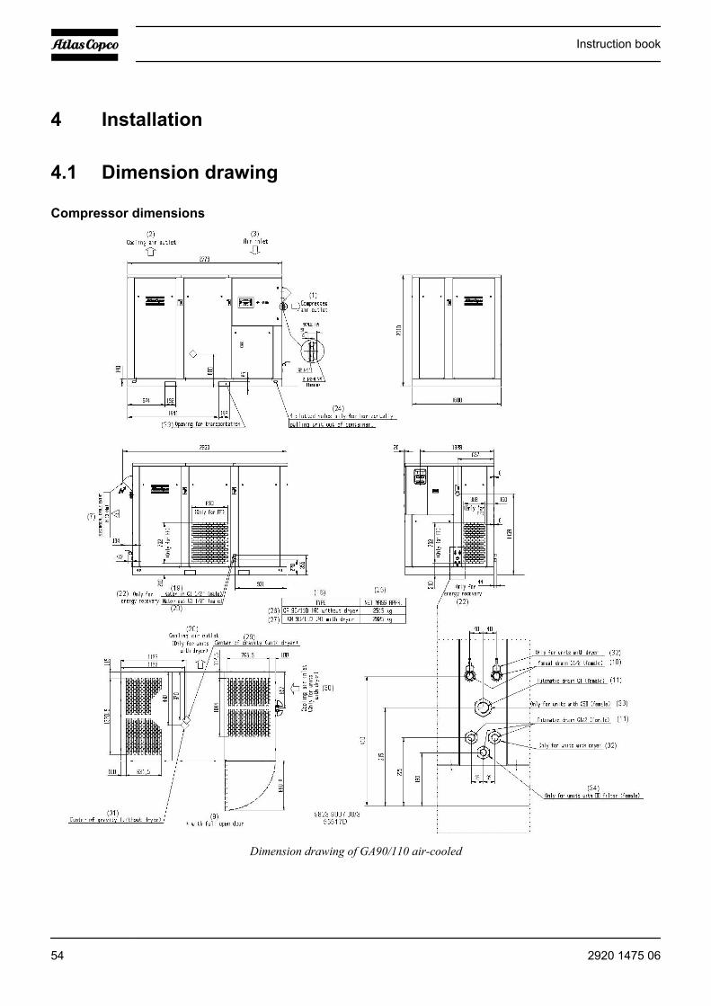
4 Installation
4.1 Dimension drawing
Compressor dimensions
Dimension drawing of GA90/110 air-cooled
Instruction book
54 2920 1475 06
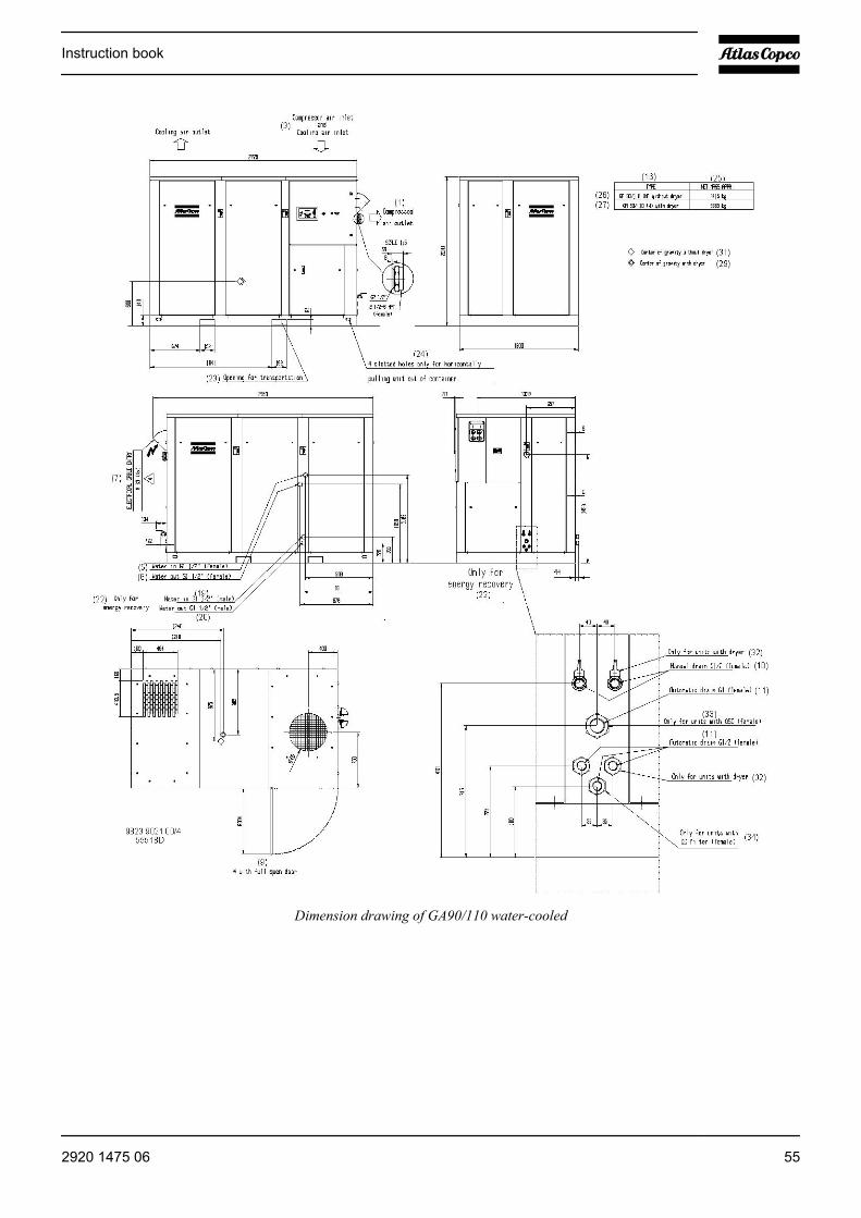
Dimension drawing of GA90/110 water-cooled
Instruction book
2920 1475 06 55
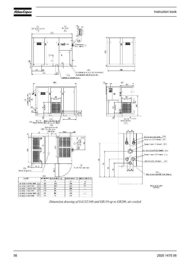
Dimension drawing of GA132/160 and GR110 up to GR200, air-cooled
Instruction book
56 2920 1475 06
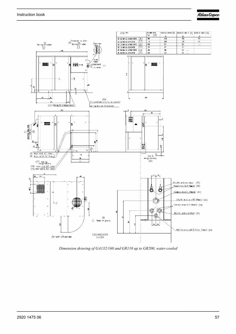
Dimension drawing of GA132/160 and GR110 up to GR200, water-cooled
Instruction book
2920 1475 06 57

Dimension drawing of GA200/250 and GA315 60 Hz, air-cooled
Instruction book
58 2920 1475 06
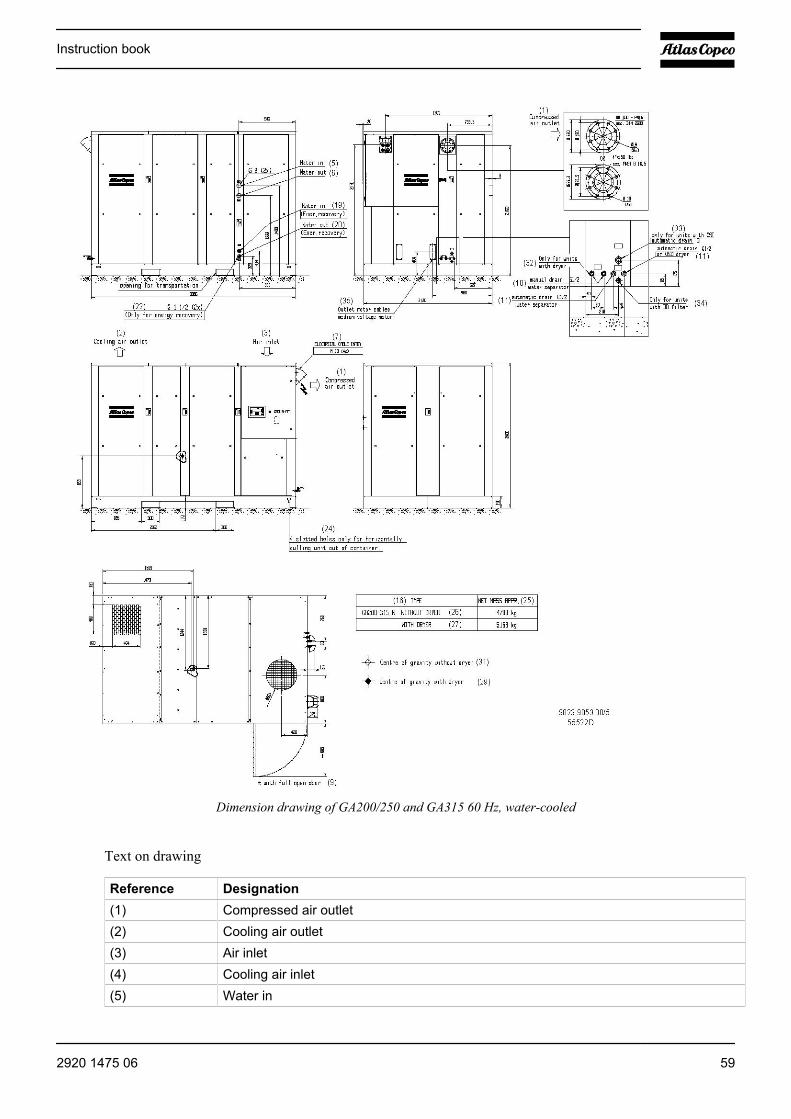
Dimension drawing of GA200/250 and GA315 60 Hz, water-cooled
Text on drawing
Reference Designation(1) Compressed air outlet(2) Cooling air outlet(3) Air inlet(4) Cooling air inlet(5) Water in
Instruction book
2920 1475 06 59
Reference Designation(6) Water out(7) Voltage supply entrance(8) Centre of gravity(9) With door fully open(10) Manual drain(11) Automatic drain(18) Centre of gravity (with energy recovery)(19) Energy recovery, water in(20) Energy recovery, water out(21) Automatic drain, only for units with OSD(22) Only for energy recovery(23) Opening for transportation(24) Slotted holes for horizontally pulling unit out of container(25) Net mass, approximately(26) For units without dryer(27) For units with dryer(28) Cooling air outlet for units with dryer(29) Centre of gravity (with dryer)(30) Cooling air inlet for units with dryer(31) Centre of gravity (without dryer)(32) Only for units with dryer(33) Only for units with OSD(34) Only for units with DD filter(35) Outlet motor cables medium-voltage motor(36) Low voltage(37) Medium voltage(38) For feature dryer add(39) Without motor(40) For feature DD filter add
Instruction book
60 2920 1475 06
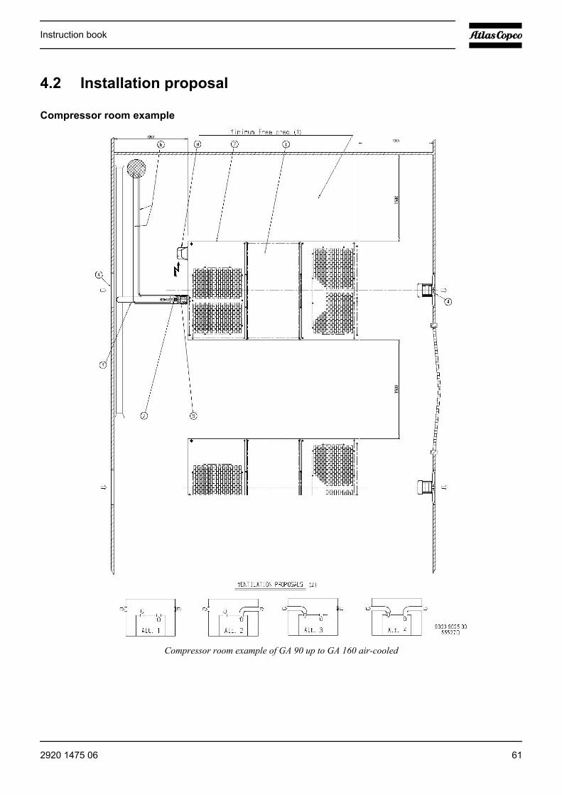
4.2 Installation proposal
Compressor room example
Compressor room example of GA 90 up to GA 160 air-cooled
Instruction book
2920 1475 06 61
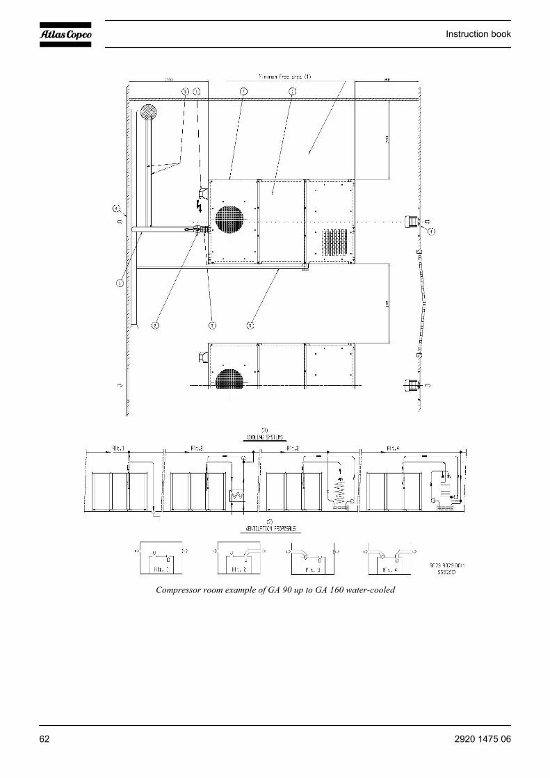
Compressor room example of GA 90 up to GA 160 water-cooled
Instruction book
62 2920 1475 06
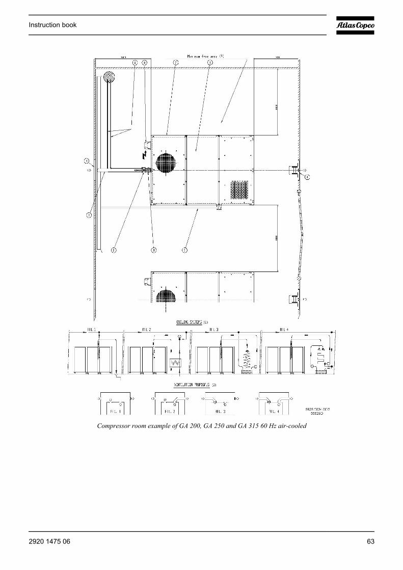
Compressor room example of GA 200, GA 250 and GA 315 60 Hz air-cooled
Instruction book
2920 1475 06 63

Compressor room example of GA 200, GA 250 and GA 315 60 Hz water-cooled
Text on drawing
Reference Designation(1) Minimum free area(2) Ventilation proposals(3) Cooling systems
Instruction book
64 2920 1475 06
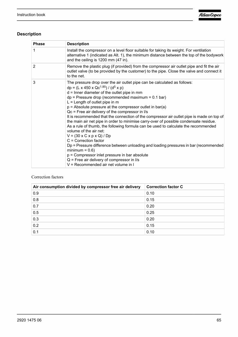
Description
Phase Description1 Install the compressor on a level floor suitable for taking its weight. For ventilation
alternative 1 (indicated as Alt. 1), the minimum distance between the top of the bodyworkand the ceiling is 1200 mm (47 in).
2 Remove the plastic plug (if provided) from the compressor air outlet pipe and fit the airoutlet valve (to be provided by the customer) to the pipe. Close the valve and connect itto the net.
3 The pressure drop over the air outlet pipe can be calculated as follows:dp = (L x 450 x Qc1.85) / (d5 x p)d = Inner diameter of the outlet pipe in mmdp = Pressure drop (recommended maximum = 0.1 bar)L = Length of outlet pipe in mp = Absolute pressure at the compressor outlet in bar(a)Qc = Free air delivery of the compressor in l/sIt is recommended that the connection of the compressor air outlet pipe is made on top ofthe main air net pipe in order to minimise carry-over of possible condensate residue.As a rule of thumb, the following formula can be used to calculate the recommendedvolume of the air net:V = (30 x C x p x Q) / DpC = Correction factorDp = Pressure difference between unloading and loading pressures in bar (recommendedminimum = 0.6)p = Compressor inlet pressure in bar absoluteQ = Free air delivery of compressor in l/sV = Recommended air net volume in l
Correction factors
Air consumption divided by compressor free air delivery Correction factor C0.9 0.100.8 0.150.7 0.200.5 0.250.3 0.200.2 0.150.1 0.10
Instruction book
2920 1475 06 65
Phase Description4 The inlet grids and ventilation fan should be installed in such a way that any recirculation
of cooling air to the compressor is avoided. The maximum air velocity through the grids is5 m/s (16.5 ft/s).The required ventilation to limit the compressor room temperature can be calculated asfollows:On air-cooled compressors: Qv = 0.92 N/dTOn water-cooled compressors: Qv = 0.1 N/dTQv = Required ventilation capacity in m3/sN = Shaft input of compressor in kWdT = Temperature increase in compressor roomIf cooling air ducts are installed, the maximum allowable pressure drop over the ducts is30 Pa (0.12 in wc). The maximum pressure drop depends on the ambient temperature.The fan capacity should match the compressor fan capacity at a pressure head equal tothe pressure drop caused by the cooling air outlet ducts. Consult Atlas Copco.
5 A water shut-off valve and water drain valve in the compressor water inlet pipe and outletpipe can be installed by the customer. If water shut-off valves are installed, a safety devicewith set pressure according to the maximum cooling water inlet pressure has to be installedbetween the compressor water outlet pipe and the shut-off valve. When operating the unit,the operator must ensure that the cooling water system cannot be blocked.The above mentioned also applies for the energy recovery cooling system.Remove the plastic plugs (if provided) from the compressor water pipes and connect thepipes to the cooling water circuit.
6 Remove the plastic plugs (if provided) from the condensate outlets and fit the manualcondensate drain valve. Lay out the drain piping towards the condensate collector. Thedrain pipes must not dip into the water of the drain collector. It is recommended to providea funnel to allow visual inspection of the condensate flow.
7 Location of the Elektronikon regulator.8 See Electric cable size for the recommended size of the supply cables. Check that the
electrical connections correspond to the local codes. The installation must be earthed andprotected against short circuits by fuses in all phases. An isolating switch must be installednear the compressor.
9 Location of a pipe coupling
Instruction book
66 2920 1475 06
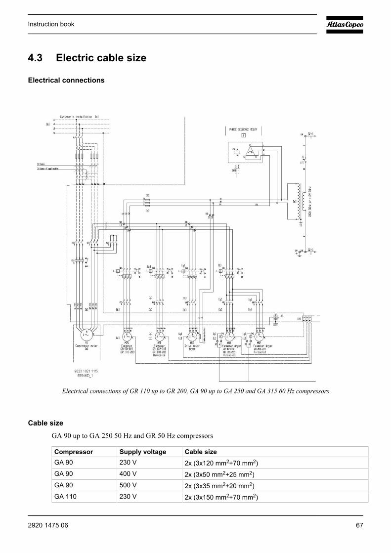
4.3 Electric cable size
Electrical connections
Electrical connections of GR 110 up to GR 200, GA 90 up to GA 250 and GA 315 60 Hz compressors
Cable size
GA 90 up to GA 250 50 Hz and GR 50 Hz compressors
Compressor Supply voltage Cable sizeGA 90 230 V 2x (3x120 mm2+70 mm2)GA 90 400 V 2x (3x50 mm2+25 mm2)GA 90 500 V 2x (3x35 mm2+20 mm2)GA 110 230 V 2x (3x150 mm2+70 mm2)
Instruction book
2920 1475 06 67

Compressor Supply voltage Cable sizeGA 110 400 V 2x (3x70 mm2+35 mm2)GA 110 500 V 2x (3x50 mm2+25 mm2)GA 132 230 V 2x (3x240 mm2+120 mm2)GA 132 400 V 2x (3x95 mm2+50 mm2)GA 132 500 V 2x (3x70 mm2+35 mm2)GA 160 230 V 4x (3x95 mm2+50 mm2)GA 160 400 V 2x (3x120 mm2+70 mm2)GA 160 500 V 2x (3x95 mm2+50 mm2)GA 200 400 V 2x (3x185 mm2+95 mm2)GA 200 500 V 2x (3x120 mm2+70 mm2)GA 250 400 V 2x (3x240 mm2+120 mm2)GA 250 500 V 2x (3x150 mm2+70 mm2)
GA 90 up to GA 315 60 Hz and GR 60 Hz IEC compressors
Compressor Supply voltage Cable sizeGA 90 220 - 230 V 2x (3x150 mm2+70 mm2)GA 90 380 V 2x (3x70 mm2+35 mm2)GA 90 440 - 460V 2x (3x50 mm2+25 mm2)GA 110 220 - 230 V 2x (3x185 mm2+95 mm2)GA 110 380 V 2x (3x95 mm2+50 mm2)GA 110 440 - 460V 2x (3x70 mm2+35 mm2)GA 160 380 V 2x (3x120 mm2+70 mm2)GA 160 440 - 460V 2x (3x95 mm2+50 mm2)GA 200 380 V 2x (3x185 mm2+95 mm2)GA 200 440 - 460V 2x (3x150 mm2+70 mm2)GA 250 380 V 2x (3x240 mm2+120 mm2)GA 250 440 - 460V 2x (3x185 mm2+95 mm2)GA 315 380 V 4x (3x95 mm2+50 mm2)GA 315 440 - 460V 2x (3x240 mm2+120 mm2)
GA 90 up to GA 315 60 Hz and GR 60 Hz, CSA/UL compressors
Compressor Supply voltage Cable sizeGA 90 440 - 460V 2x (3xAWG00+AWG4)GA 90 575 V 2x (3xAWG2+AWG6)GA 110 440 - 460V 2x (3xAWG00+AWG3)GA 110 575 V 2x (3xAWG1+AWG6)GA 160 440 - 460V 2x (3xMCM250+AWG2) or (4X3XAWG2+AWG)GA 160 575 V 2x(3XAWG000+AWG3)GA 200 440 - 460V 2x (3xMCM500+AWG0)
Instruction book
68 2920 1475 06
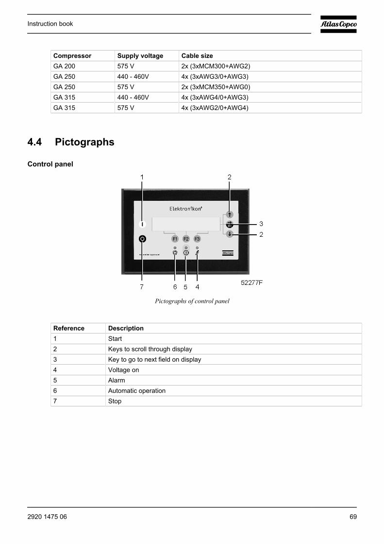
Compressor Supply voltage Cable sizeGA 200 575 V 2x (3xMCM300+AWG2)GA 250 440 - 460V 4x (3xAWG3/0+AWG3)GA 250 575 V 2x (3xMCM350+AWG0)GA 315 440 - 460V 4x (3xAWG4/0+AWG3)GA 315 575 V 4x (3xAWG2/0+AWG4)
4.4 Pictographs
Control panel
Pictographs of control panel
Reference Description1 Start2 Keys to scroll through display3 Key to go to next field on display4 Voltage on5 Alarm6 Automatic operation7 Stop
Instruction book
2920 1475 06 69
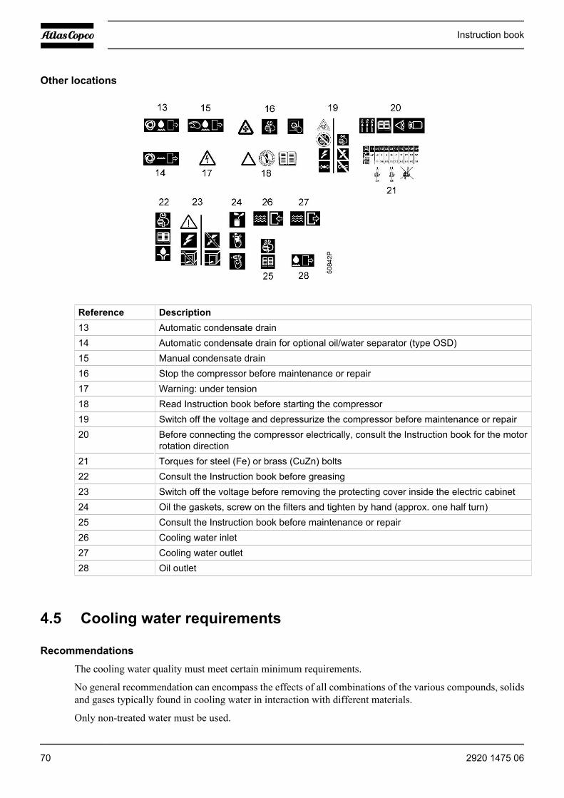
Other locations
Reference Description13 Automatic condensate drain14 Automatic condensate drain for optional oil/water separator (type OSD)15 Manual condensate drain16 Stop the compressor before maintenance or repair17 Warning: under tension18 Read Instruction book before starting the compressor19 Switch off the voltage and depressurize the compressor before maintenance or repair20 Before connecting the compressor electrically, consult the Instruction book for the motor
rotation direction21 Torques for steel (Fe) or brass (CuZn) bolts22 Consult the Instruction book before greasing23 Switch off the voltage before removing the protecting cover inside the electric cabinet24 Oil the gaskets, screw on the filters and tighten by hand (approx. one half turn)25 Consult the Instruction book before maintenance or repair26 Cooling water inlet27 Cooling water outlet28 Oil outlet
4.5 Cooling water requirements
Recommendations
The cooling water quality must meet certain minimum requirements.
No general recommendation can encompass the effects of all combinations of the various compounds, solidsand gases typically found in cooling water in interaction with different materials.
Only non-treated water must be used.
Instruction book
70 2920 1475 06
This recommendation is a general guide line for acceptable coolant quality.
Type of system
First, it is important to consider whether you are dealing with a closed system or an open system. In a closedsystem, the same cooling water circulates through a system without contact with air.
An open system is a pass-through system, or a circulating system with a cooling tower. In the latter case, thecomposition of the water that enters the cooler must be considered, and not the composition of the make-upwater. Due to the evaporative effect in the cooling tower, much higher concentrations of ions can be obtainedin the circulating water than in the make-up water.
Ryznar stability index (RSI)
The Ryznar Stability Index (RSI) is a parameter for predicting whether water will tend to dissolve or precipitatecalcium carbonate. The adhesion of scaling deposits and their effect are different on different materials, butthe equilibrium of the water (scaling or corrosive) is only determined by its actual pH value and by thesaturation pH value (pHs).
The saturation pH value is determined by the relationship between the calcium hardness, the total alkalinity,the total solids concentration and the temperature.
The Ryznar Index is calculated as follows :
RSI = 2*pHs - pH
Symbol ExplanationpH Measured pH (at room temperature) of water samplepHs pH at saturation
The pHs is calculated by using :
pHs = (9.3 + A + B) - (C + D)
Symbol ExplanationA Depends on the total solids concentration (mg/l)B Depends on the highest cooling water temperature (˚C/˚F), (T=75 ˚C/167 ˚F)C Depends on the calcium hardness (ppm CaCO3)
D Depends on the HCO3- concentration or M-alkalinity (mval/l)
The values of A, B, C and D can be found in the following table.
Total dissolvedsolids (mg/l)
A Temperature(˚C)
B Ca-hardness (ppmCaCO3)
C M-alkalinity (mval/l) D
50 - 300 0.1 0 - 1 2.6 10 - 11 0.6 0.20 - 0.22 1.0400-1000 0.2 2 - 6 2.5 12 - 13 0.7 0.24 - 0.26 1.1 7 - 9 2.4 14 - 17 0.8 0.28 - 0.34 1.2 10 - 13 2.3 18 - 22 0.9 0.36 - 0.44 1.3 14 - 17 2.2 23 - 27 1.0 0.46 - 0.54 1.4 18 - 21 2.1 28 - 34 1.1 0.56 - 0.70 1.5 22 - 27 2.0 35 - 43 1.2 0.72 - 0.88 1.6
Instruction book
2920 1475 06 71

Total dissolvedsolids (mg/l)
A Temperature(˚C)
B Ca-hardness (ppmCaCO3)
C M-alkalinity (mval/l) D
28 - 31 1.9 44 - 55 1.3 0.90 - 1.10 1.7 32 - 37 1.8 56 - 69 1.4 1.12 - 1.38 1.8 38 - 44 1.7 70 - 87 1.5 1.40 - 1.76 1.9 45 - 50 1.6 88 - 110 1.6 1.78 - 2.20 2.0 51 - 56 1.5 111 - 138 1.7 2.22 - 2.78 2.1 57 - 63 1.4 138 - 174 1.8 2.80 - 3.54 2.2 64 - 71 1.3 175 - 220 1.9 3.54 - 4.40 2.3 72 - 80 1.2 230 - 270 2.0 4.6 - 5.4 2.4 280 - 340 2.1 5.6 - 7.0 2.5 350 - 430 2.2 7.2 - 8.8 2.6 440 - 550 2.3 9.0 - 11.0 2.7 560 - 690 2.4 11.2 - 13.8 2.8 700 - 870 2.5 14.0 - 17.6 2.9 880 - 1000 2.6 17.8 - 20.0 3.0
Interpretation of the value obtained
RSI Water condition ActionRSI<3.9 Very high scale formation Water cannot be used.4.0<RSI<5.5 High boiler scale formation Regular inspection and descaling operation
necessary.5.6<RSI<6.2 Slight boiler scale formation Water treatment not necessary.
Occasional inspection recommended.6.3<RSI<6.8 Neutral water Water treatment not necessary.
Occasional inspection recommended.6.9<RSI<7.5 Slight corrosion at higher
temperatureWater treatment not necessary.Occasional inspection recommended.
7.6<RSI<9.0 Strong corrosion Regular inspection necessary, use of corrosioninhibitor recommended.
9.1<RSI<11 Very strong corrosion Regular inspection necessary, use of corrosioninhibitor required.
RSI>11 Very strong corrosion incomplete water system
Water should not be used.
The table indicates that distilled or demineralised water should never be used, as their RSI is > 11.
The RSI only indicates the equilibrium of scaling - descaling. A cooling water showing good RSI conditionscan still be unsuitable due to other factors.
From the table above, the RSI index should be between 5.6 and 7.5; otherwise, contact a specialist.
pH
The effect of pH is already calculated in the Ryznar index, but the pH itself has some additional limitations :6.8 < pH
Instruction book
72 2920 1475 06
Total dissolved solids (TDS)
This is the sum of all the ions in the water. It can be derived from the dry residue after evaporation (but notincluding suspended solids), or it can be estimated from the electrical conductivity.
In a closed system, the following limits apply : TDS < 3000 mg/l (< 3800 microS/cm)
For an open system, the following limits apply : TDS < 450 mg/l ( < 580 microS/cm)
Chlorides (Cl-)
Chloride ions will create pitting corrosion on stainless steel. Their concentration should be limited:
Closed cooling system : chlorides < 500 ppm
Open cooling system : chlorides < 150 ppm
However, if the water is scaling, lower limits should be used. (See The Ryznar stability index (RSI)).
Free chlorine (Cl2)
A level of 0.5 ppm should not be exceeded for long periods.
For shock treatments, a maximum limit of 2 ppm for maximum 30 minutes/day applies.
Sulphates (SO4--)
Closed cooling system : sulphates < 400 ppm
Open cooling system : sulphates < 150 ppm
Carbonate hardness
Closed cooling system : 50-1000 ppm CaCO3
Open cooling system : 50-500 ppm CaCO3
HCO3- / SO4
2- should be > 1
Ammonia
< 0.5 ppm
Copper
< 1 ppm
Iron and manganese
< 1 ppm
Organics
No algae
No oil
Instruction book
2920 1475 06 73

Suspended solids
Non-soluble particles, size < 1 mm.
< 10 ppm
Instruction book
74 2920 1475 06

5 Operating instructions
5.1 Initial start-up
Warning
The operator must apply all relevant Safety precautions.
Switch off the voltage before making any adjustment.
Outdoor/altitude operation
If the compressor is installed outdoors or if the air inlet temperature can be below freezing point, precautionsmust be taken. In this case, and also if operating at high altitude, consult Atlas Copco.
Moving/lifting
The compressor can be moved by a lift truck using the slots in the frame. Make sure that the forks protrudefrom the other side of the frame. The compressor can also be lifted after inserting beams in the slots. Makesure that the beams cannot slide and that they protrude from the frame equally. The chains must be held parallelto the bodywork by chain spreaders in order not to damage the compressor. The lifting equipment must beplaced in such a way that the compressor is lifted perpendicularly. Lift gently and avoid twisting.
Instruction book
2920 1475 06 75
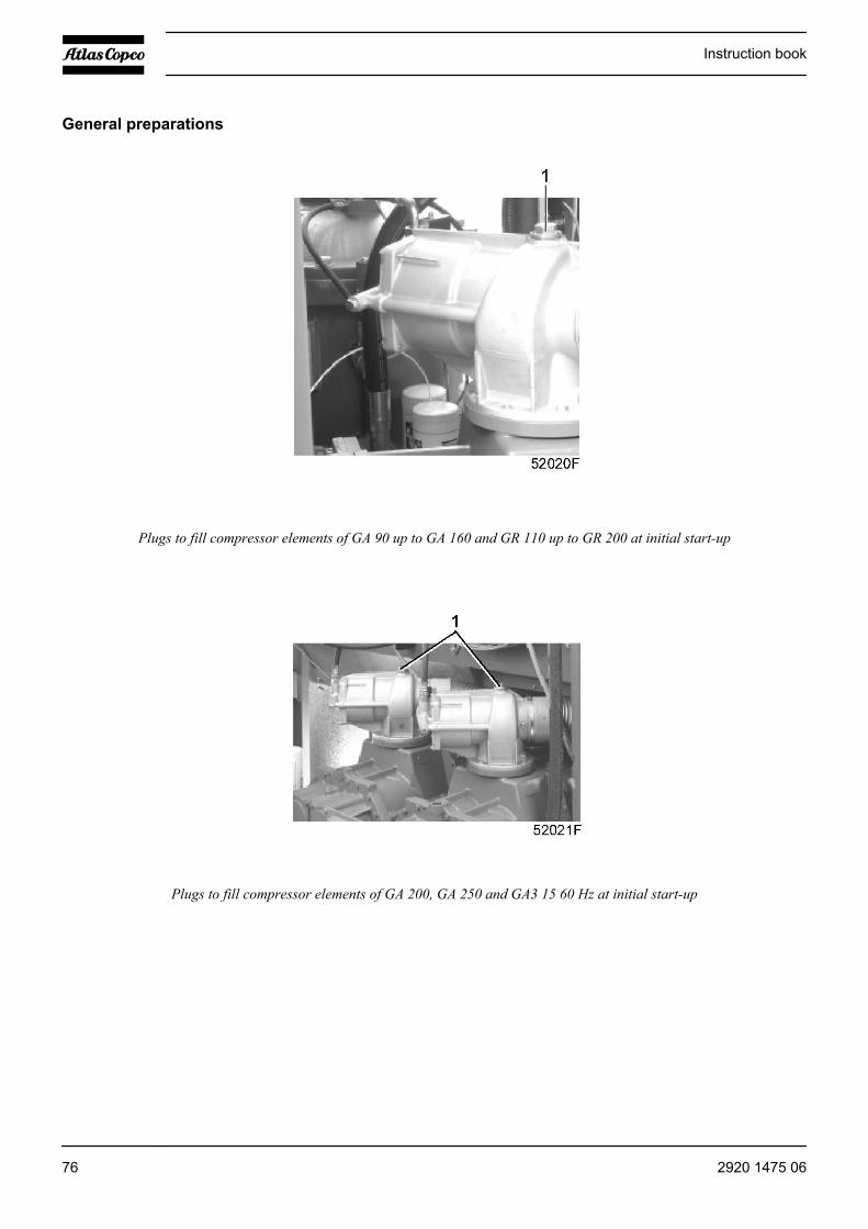
General preparations
Plugs to fill compressor elements of GA 90 up to GA 160 and GR 110 up to GR 200 at initial start-up
Plugs to fill compressor elements of GA 200, GA 250 and GA3 15 60 Hz at initial start-up
Instruction book
76 2920 1475 06

Step Action1 Install the compressor, see the sections Dimension drawing, Installation proposal and
Electric cable size.2 Affix the sticker, giving brief operating instructions, next to the control panel.
Stick labels near the control panel to warn the operator that:• the compressor may start automatically after a voltage failure• the compressor is automatically started and stopped• the compressor may be remotely controlled
3 A number of VCI (Volatile Corrosion Inhibitor) plates are provided inside the bodywork toprotect the compressor against corrosion. Remove the plates.
4 Remove filler plugs (1).On GA90 up to GA250 and GA315 60 Hz and GR110 up to GR200, pour approx. 1 l (0.26US gal/0.22 Imp gal ) of oil into the compressor elements.Refit the plugs.
5 Check that the compressor is filled with oil; the pointer of the oil level indicator should bein the green range (see the section Oil change).
Protection during transport
Transport fixtures for GA 90 up to GA 160
Instruction book
2920 1475 06 77
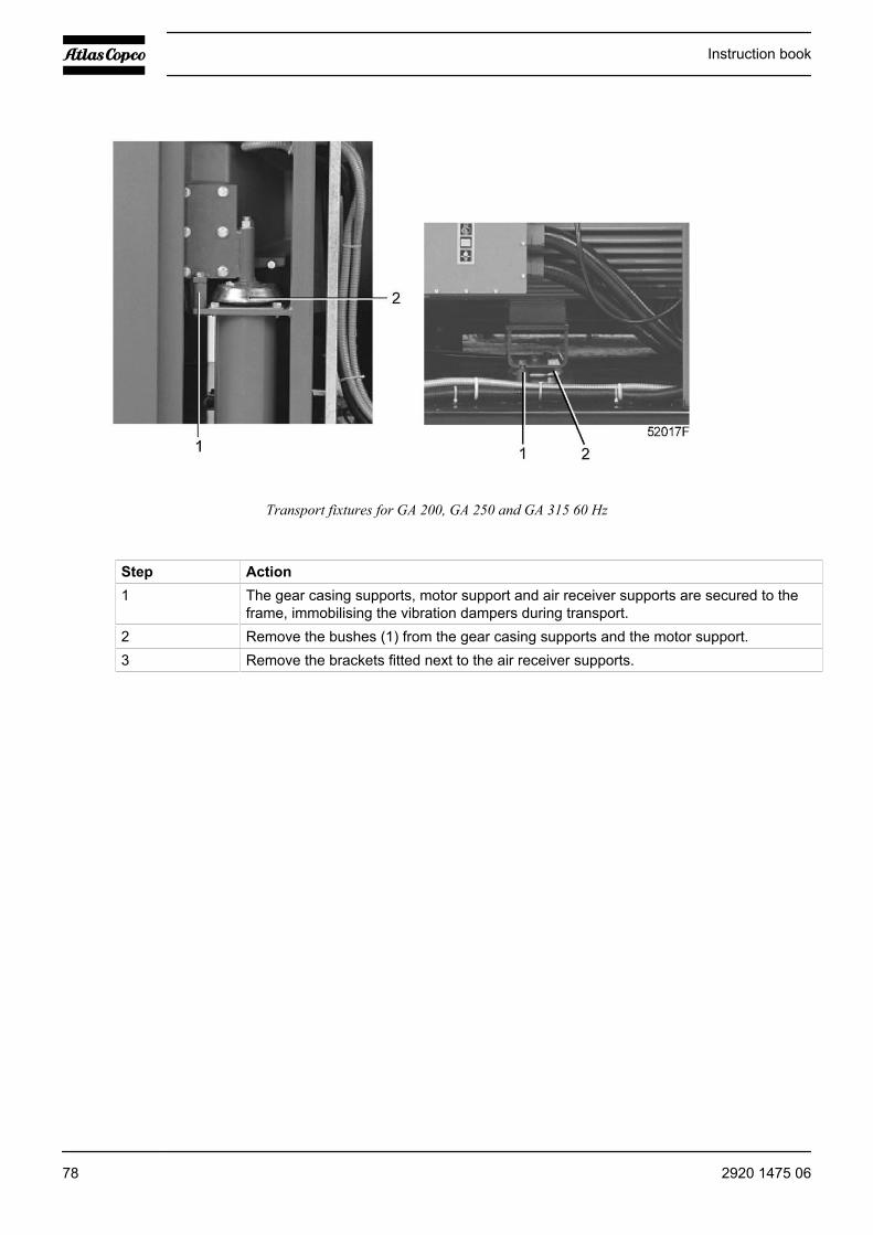
Transport fixtures for GA 200, GA 250 and GA 315 60 Hz
Step Action1 The gear casing supports, motor support and air receiver supports are secured to the
frame, immobilising the vibration dampers during transport.2 Remove the bushes (1) from the gear casing supports and the motor support.3 Remove the brackets fitted next to the air receiver supports.
Instruction book
78 2920 1475 06
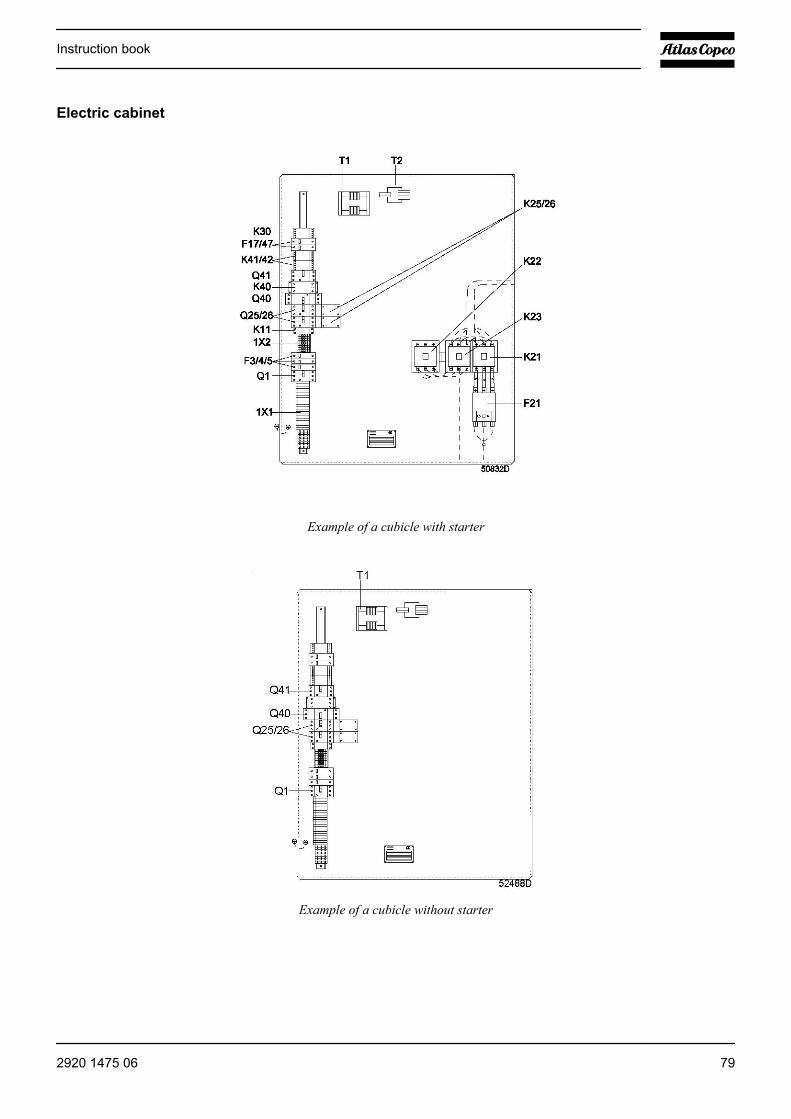
Electric cabinet
Example of a cubicle with starter
Example of a cubicle without starter
Instruction book
2920 1475 06 79
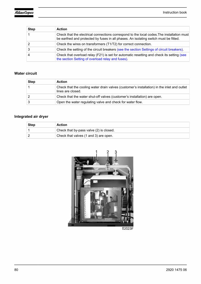
Step Action1 Check that the electrical connections correspond to the local codes.The installation must
be earthed and protected by fuses in all phases. An isolating switch must be fitted.2 Check the wires on transformers (T1/T2) for correct connection.3 Check the setting of the circuit breakers (see the section Settings of circuit breakers).4 Check that overload relay (F21) is set for automatic resetting and check its setting (see
the section Setting of overload relay and fuses).
Water circuit
Step Action1 Check that the cooling water drain valves (customer’s installation) in the inlet and outlet
lines are closed.2 Check that the water shut-off valves (customer’s installation) are open.3 Open the water regulating valve and check for water flow.
Integrated air dryer
Step Action1 Check that by-pass valve (2) is closed.2 Check that valves (1 and 3) are open.
Instruction book
80 2920 1475 06

Oil separating device
Step Action1 Remove the cover and fill vessel (1) with water to the level of water outlet (2).2 Refit the cover.
Start up
Step Action1 Close the drain valves (see the section Cooling and condensate system).2 Switch on the voltage.3 Start the compressor and stop it immediately. Check the rotation direction of the drive
motor while the motor is coasting to a stop.4 If the rotation direction is wrong, press the emergency stop button, switch off the voltage
and reverse two incoming electric lines.The correct direction of rotation is indicated for the drive motor by an arrow on the gearcasing and for the fan motors by arrows on the motor housings.
4 Run the compressor for a few minutes and check that it is operating normally.
5.2 Before starting
Warning
The operator must apply all relevant Safety precautions.
If the water system was drained, make sure the drain valves are closed.
Instruction book
2920 1475 06 81

Control panel
Step Action1 Switch on the voltage. Voltage on LED (6) lights up.2 Close the condensate drain valves (see the section Cooling and condensate system).3 Open the air outlet valve.4 Check the oil level indicator (see the section Oil change). The pointer should be in the
green range or orange range.5 On compressors with integrated dryer, check that the by-pass valve is closed and that the
inlet and outlet valves of the dryer are open (see the section Initial start-up).Open the water shut-off valves and the water regulating valve.
5.3 Starting
Warning
The operator must apply all relevant Safety precautions.
On Full-Feature compressors, switch on the voltage 4 hours before starting in order toenergise the crankcase heater of the refrigerant compressor.
Instruction book
82 2920 1475 06

Control panel
Control panel of MkIV regulator
Step Action1 Press start button (1). The compressor starts running in unloaded condition. Automatic
operation LED (8) lights up.2 Approx. 10 seconds later (programmable), the compressor starts running loaded. The
message on display (2) changes from “Automatically unloaded” to “Automatically loaded”.3 On water-cooled compressors, regulate the cooling water flow with the compressor
running loaded. Adjust the water flow to obtain the most suitable air temperature at theoutlet of the compressor elements. The temperature must be between 2 and approx. 7 ˚C(4 and approx. 13 ˚F) above the relevant temperature in the diagram.
Instruction book
2920 1475 06 83
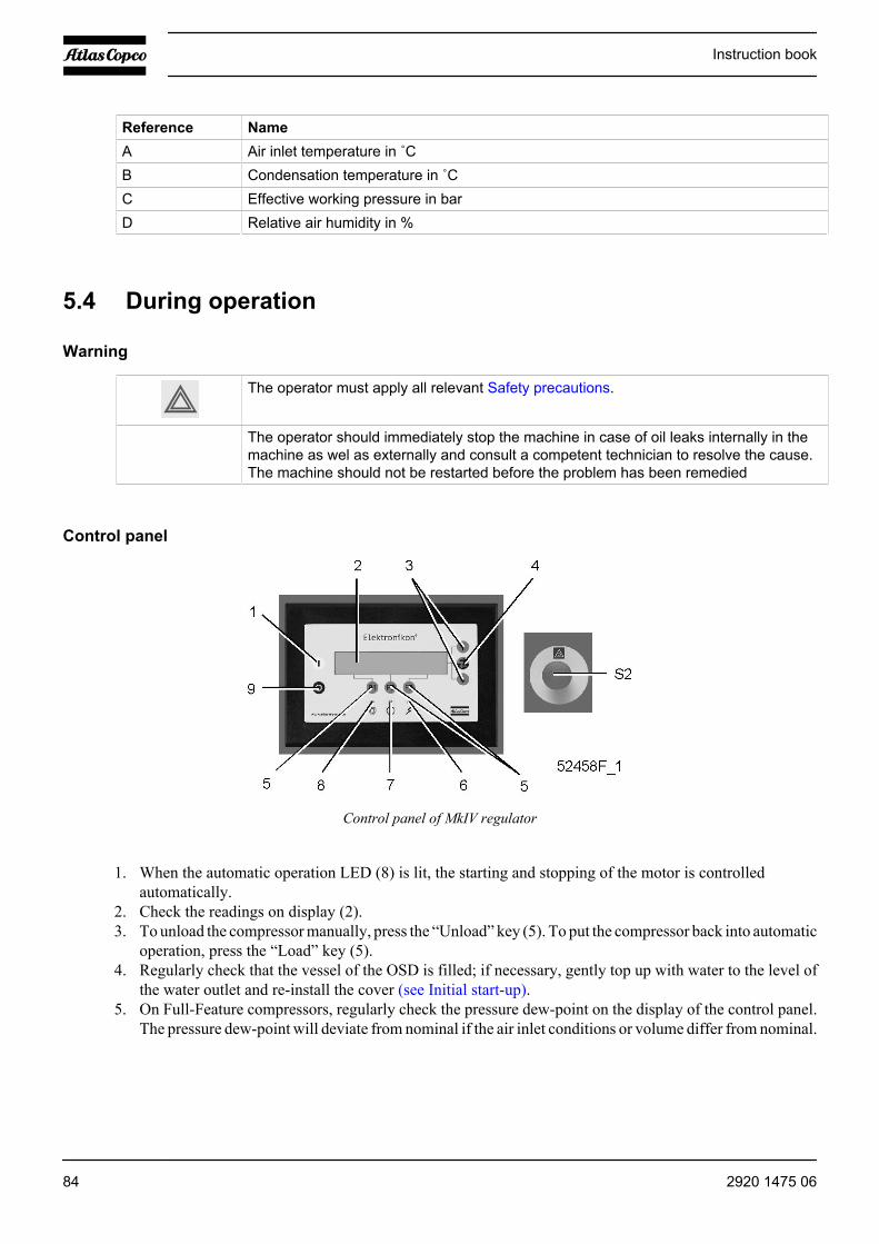
Reference NameA Air inlet temperature in ˚CB Condensation temperature in ˚CC Effective working pressure in barD Relative air humidity in %
5.4 During operation
Warning
The operator must apply all relevant Safety precautions.
The operator should immediately stop the machine in case of oil leaks internally in themachine as wel as externally and consult a competent technician to resolve the cause.The machine should not be restarted before the problem has been remedied
Control panel
Control panel of MkIV regulator
1. When the automatic operation LED (8) is lit, the starting and stopping of the motor is controlledautomatically.
2. Check the readings on display (2).3. To unload the compressor manually, press the “Unload” key (5). To put the compressor back into automatic
operation, press the “Load” key (5).4. Regularly check that the vessel of the OSD is filled; if necessary, gently top up with water to the level of
the water outlet and re-install the cover (see Initial start-up).5. On Full-Feature compressors, regularly check the pressure dew-point on the display of the control panel.
The pressure dew-point will deviate from nominal if the air inlet conditions or volume differ from nominal.
Instruction book
84 2920 1475 06

If the compressor is stopped, it may start automatically.
5.5 Checking the display
Warning
Before carrying out any maintenance, repair work or adjustment, stop the compressor,press the emergency stop button and switch off the voltage. Close the air outlet valve andopen the manual condensate drain valve.
Control panel
Step Action1 Regularly check the display for readings and messages. Normally, the main display is
shown, indicating the compressor outlet pressure, the status of the compressor and thefunctions of the keys below the display.
2 Always check the display and remedy the problem if alarm LED (7) is lit or flashing.3 The display will show a service message if a service plan interval has been exceeded or
if a service level for a monitored component has been exceeded. Carry out the serviceactions of the indicated service plans or replace the component and reset the relevanttimer.
4 Regularly check the actual compressor status by pressing the arrow down key from themain screen.
Instruction book
2920 1475 06 85
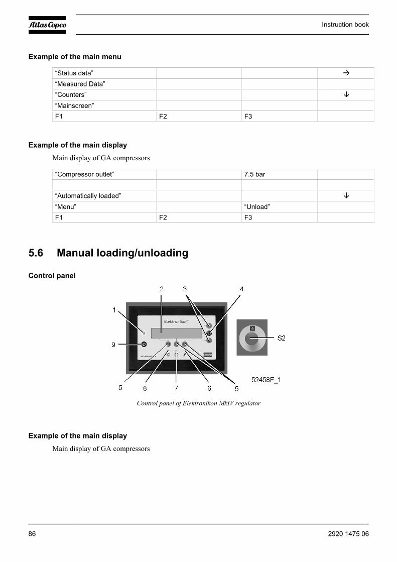
Example of the main menu
“Status data”“Measured Data”“Counters”“Mainscreen”F1 F2 F3
Example of the main display
Main display of GA compressors
“Compressor outlet” 7.5 bar
“Automatically loaded”“Menu” “Unload” F1 F2 F3
5.6 Manual loading/unloading
Control panel
Control panel of Elektronikon MkIV regulator
Example of the main display
Main display of GA compressors
Instruction book
86 2920 1475 06
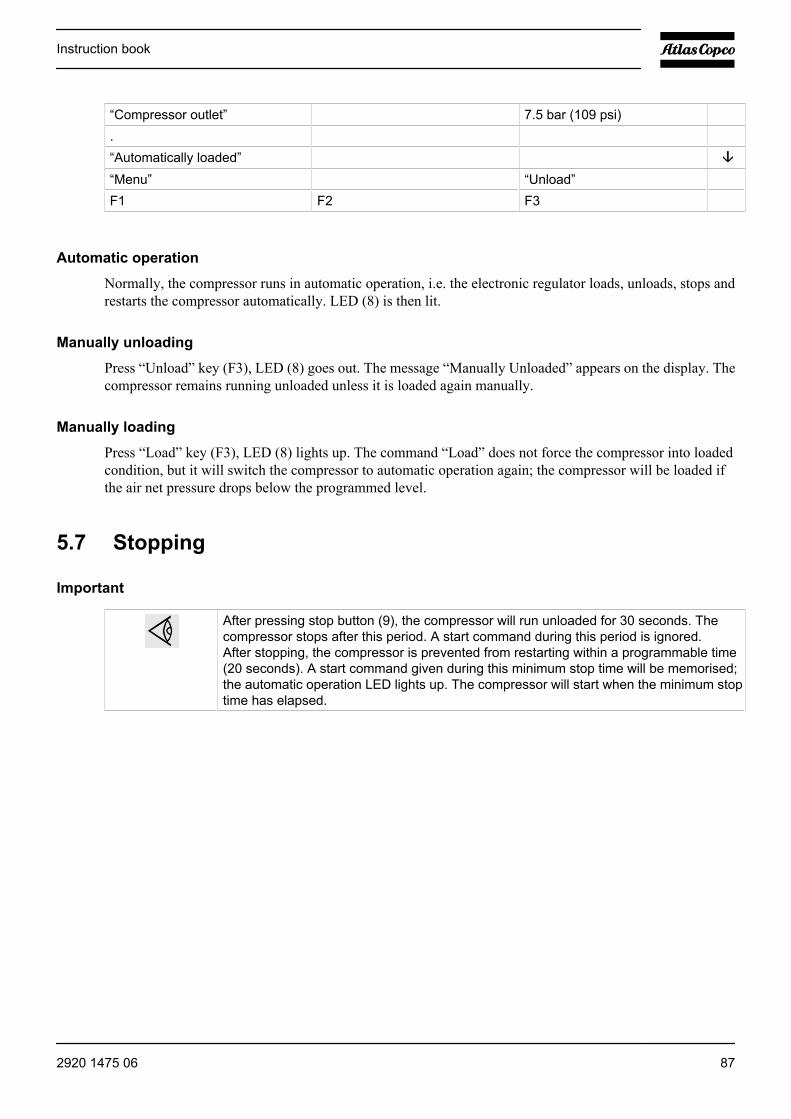
“Compressor outlet” 7.5 bar (109 psi) . “Automatically loaded” “Menu” “Unload” F1 F2 F3
Automatic operation
Normally, the compressor runs in automatic operation, i.e. the electronic regulator loads, unloads, stops andrestarts the compressor automatically. LED (8) is then lit.
Manually unloading
Press “Unload” key (F3), LED (8) goes out. The message “Manually Unloaded” appears on the display. Thecompressor remains running unloaded unless it is loaded again manually.
Manually loading
Press “Load” key (F3), LED (8) lights up. The command “Load” does not force the compressor into loadedcondition, but it will switch the compressor to automatic operation again; the compressor will be loaded ifthe air net pressure drops below the programmed level.
5.7 Stopping
Important
After pressing stop button (9), the compressor will run unloaded for 30 seconds. Thecompressor stops after this period. A start command during this period is ignored.After stopping, the compressor is prevented from restarting within a programmable time(20 seconds). A start command given during this minimum stop time will be memorised;the automatic operation LED lights up. The compressor will start when the minimum stoptime has elapsed.
Instruction book
2920 1475 06 87
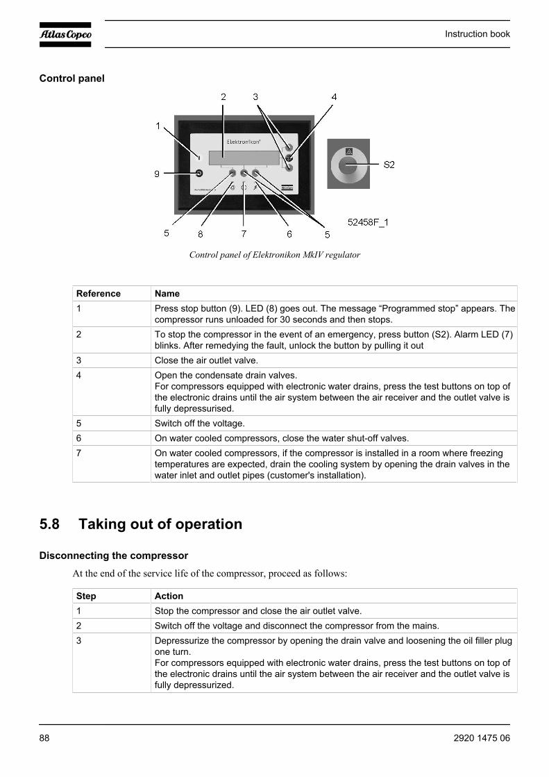
Control panel
Control panel of Elektronikon MkIV regulator
Reference Name1 Press stop button (9). LED (8) goes out. The message “Programmed stop” appears. The
compressor runs unloaded for 30 seconds and then stops.2 To stop the compressor in the event of an emergency, press button (S2). Alarm LED (7)
blinks. After remedying the fault, unlock the button by pulling it out3 Close the air outlet valve.4 Open the condensate drain valves.
For compressors equipped with electronic water drains, press the test buttons on top ofthe electronic drains until the air system between the air receiver and the outlet valve isfully depressurised.
5 Switch off the voltage.6 On water cooled compressors, close the water shut-off valves.7 On water cooled compressors, if the compressor is installed in a room where freezing
temperatures are expected, drain the cooling system by opening the drain valves in thewater inlet and outlet pipes (customer's installation).
5.8 Taking out of operation
Disconnecting the compressor
At the end of the service life of the compressor, proceed as follows:
Step Action1 Stop the compressor and close the air outlet valve.2 Switch off the voltage and disconnect the compressor from the mains.3 Depressurize the compressor by opening the drain valve and loosening the oil filler plug
one turn.For compressors equipped with electronic water drains, press the test buttons on top ofthe electronic drains until the air system between the air receiver and the outlet valve isfully depressurized.
Instruction book
88 2920 1475 06
Step Action4 Shut off and depressurize the part of the air net which is connected to the outlet valve.
Disconnect the compressor air outlet pipe from the air net.5 Drain the oil and condensate circuits.
On water cooled compressors, drain the water circuits.6 Disconnect the compressor condensate piping from the condensate drain net.7 On water cooled compressors, disconnect the cooling water pipes from the compressor.
5.9 Use of air receiver
Instructions
Step Action1 This vessel can contain pressurized air; please be aware of its potential danger in case of
misuse.2 This vessel shall only be used as compressed air/oil separator and must be operated within
the specified limits as mentioned on the dataplate.3 No alterations shall be made to this vessel by welding, drilling or other methods of
mechanical working without written permission of the manufacturer.4 Original bolts have to be used after opening for inside inspection. Maximum torque has to
be taken into consideration.5 Devices for pressure and temperature control must always remain attached to this vessel.6 This vessel has been designed and built to guarantee an operational lifetime in excess of
20 years and an infinite number of pressure load cycles. Therefore there is no intrinsicneed for in-service inspection of the vessel when used within its design limits and in itsintended application. National legislation however may require in-service inspection.
Instruction book
2920 1475 06 89

6 Maintenance
6.1 Preventive maintenance schedule
Warning
Before carrying out any maintenance, repair work or adjustment, proceedas follows:• Stop the compressor.• Press emergency stop button (S2).• Close the air outlet valve and open the manual condensate drain valves.• For compressors equipped with electronic water drains, press the test
buttons on top of the electronic drains until the air system between the airreceiver and the outlet valve is fully depressurised.
• Switch off the voltage.• Open and lock the isolating switch.
The operator must apply all relevant Safety precautions.
Warranty - Product Liability
Use only authorised parts. Any damage or malfunction caused by the use of unauthorised parts is not coveredby Warranty or Product Liability.
General
When servicing, replace all removed gaskets, O-rings and washers.
Preventive maintenance schedule
Period Running hours OperationDaily 8 Check readings on display.Daily 8 Check that condensate is discharged during loading.Daily 8 Check oil level. Before starting, the level should be in the middle of the
sight-glass.Weekly -- Drain condensate from the air receiver, if installedWeekly 50 On compressors equipped with an OSD, check the oil level in the oil
collectors. If necessary, empty the collectors and take the oil to thelocal collection service. Keep the covers of the vessels in place toprevent possible evaporation.
3-Monthly -- On compressors equipped with an OSD, remove, dismantle and cleanthe float valve of the condensate traps.
3-Monthly -- Clean compressor.3-Monthly -- Check for possible leaks.3-Monthly 500 Check the coolers; clean them if necessary. See the section Coolers.3-Monthly -- Remove air filter elements and inspectYearly -- Have safety valve tested
Instruction book
90 2920 1475 06

Period Running hours OperationYearly -- Have all flexibles inspectedYearly 4000 Replace oil filtersYearly 4000 If Roto-Inject Fluid is used, change oilYearly 8000 If Roto-Xtend Duty Fluid is used, change oil2-Yearly 8000 Have oil separator element replacedWhen displayed -- Carry out service action according to the displayed service plans.
When operating in a dusty atmosphere, inspect the air filters more frequently.Use always Atlas Copco filters.The separator element must also be replaced when the pressure difference over the elementexceeds 0.8 bar (12 psi). Check the pressure drop when the compressor is running loadedand preferably with a stable working pressure.Damaged flexibles must be replaced immediately.
Service agreements
Atlas Copco Customer Centres have a range of service agreements to suit your needs:
• An Inspection Plan• A Preventive Maintenance Plan• A Total Responsibility Plan
Contact your Customer Centre to set up a tailor-made service agreement. It will ensure optimum operationalefficiency, minimise downtime and reduce the total life cycle costs.
Service plan
A number of service operations are grouped (called Level A, Level B, Level C...). Each level stands for anumber of service actions to be carried out at the time intervals programmed in the Elektronikon regulator.
When a level is reached, a message will appear on the screen. After carrying out all service actions, the intervaltimers must be reset using the “Reset” key in the “Service” menu. Consult your Atlas Copco Service Centre.
6.2 Motors
Warning
Stop the compressor and switch off the voltage. The operator must apply all relevant Safetyprecautions.
Never mix greases of different brands or types.
Fan motors
The bearings of the fan motors are greased for life. The bearings of the fan motor must be replaced after 25000operating hours.
Instruction book
2920 1475 06 91

ABB drive motor
ABB motors must be greased with Unirex N2 or N3
50 Hz
Compressor type Interval AmountGA 90 4000 h 70 gr (2.45 oz)GA 110 4000 h 70 gr (2.45 oz)GA 132 4000 h 90 gr (3.15 oz)GA 160 4000 h 90 gr (3.15 oz)GA 200 4000 h 90 gr (3.15 oz)GA 250 4000 h 90 gr (3.15 oz)
60 Hz
Compressor type Interval AmountGA 90 4000 h 70 gr (2.45 oz)GA 110 4000 h 90 gr (3.15 oz)GA 160 4000 h 90 gr (3.15 oz)GA 200 4000 h 90 gr (3.15 oz)GA 250 4000 h 90 gr (3.15 oz)GA 315 4000 h 90 gr (3.15 oz)
WEG drive motor
WEG motors must be greased with Polyrex EM
60 Hz
Compressor type Interval D-end
Amount D-end
Interval N-end
Amount N-end
GA 90 8000 h 45 gr (1.58 oz) 8000 h 35 gr (1.23 oz)GA 110 8000 h 45 gr (1.58 oz) 8000 h 35 gr (1.23 oz)GA 160 8000 h 45 gr (1.58 oz) 8000 h 35 gr (1.23 oz)GA 200 8000 h 45 gr (1.58 oz) 8000 h 35 gr (1.23 oz)GA 250 4000 h 60 gr (2.1 oz) 4000 h 45 gr (3.15 oz)GA 315 4000 h 60 gr (2.1 oz) 4000 h 45 gr (3.15 oz)
6.3 Oil specifications
Atlas Copco Roto-Inject Fluid
Roto-Inject Fluid is a high-quality lubricant for single-stage, oil-injected rotary screw compressors. See thesection Service kits.
Instruction book
92 2920 1475 06
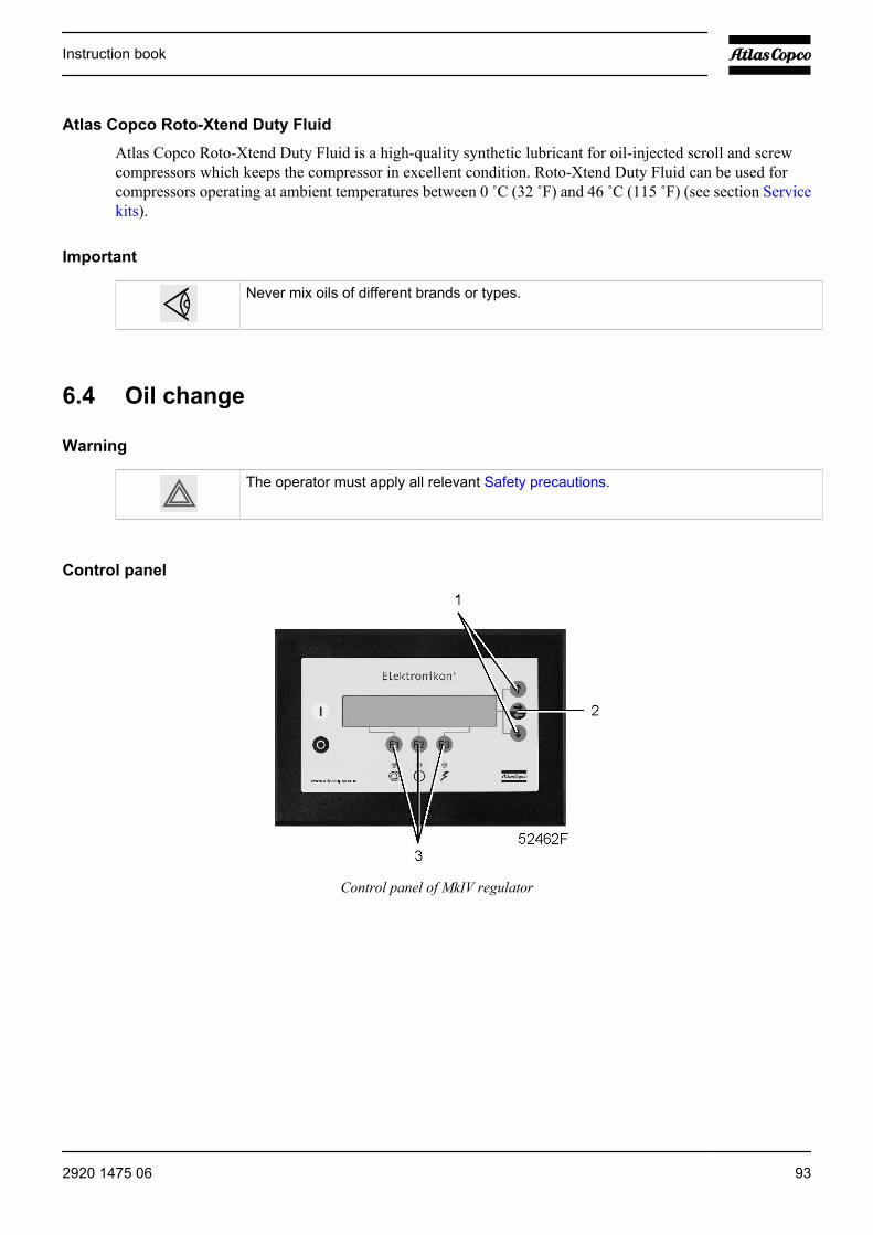
Atlas Copco Roto-Xtend Duty Fluid
Atlas Copco Roto-Xtend Duty Fluid is a high-quality synthetic lubricant for oil-injected scroll and screwcompressors which keeps the compressor in excellent condition. Roto-Xtend Duty Fluid can be used forcompressors operating at ambient temperatures between 0 ˚C (32 ˚F) and 46 ˚C (115 ˚F) (see section Servicekits).
Important
Never mix oils of different brands or types.
6.4 Oil change
Warning
The operator must apply all relevant Safety precautions.
Control panel
Control panel of MkIV regulator
Instruction book
2920 1475 06 93
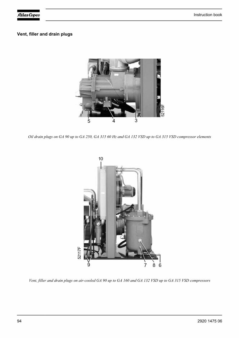
Vent, filler and drain plugs
Oil drain plugs on GA 90 up to GA 250, GA 315 60 Hz and GA 132 VSD up to GA 315 VSD compressor elements
Vent, filler and drain plugs on air-cooled GA 90 up to GA 160 and GA 132 VSD up to GA 315 VSD compressors
Instruction book
94 2920 1475 06
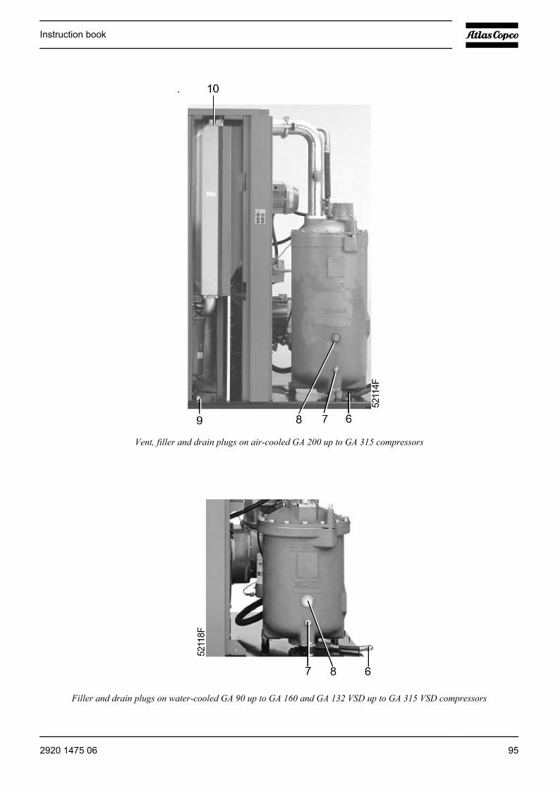
Vent, filler and drain plugs on air-cooled GA 200 up to GA 315 compressors
Filler and drain plugs on water-cooled GA 90 up to GA 160 and GA 132 VSD up to GA 315 VSD compressors
Instruction book
2920 1475 06 95

Filler and drain plugs on GA 200 up to GA 500 compressors
Instruction book
96 2920 1475 06
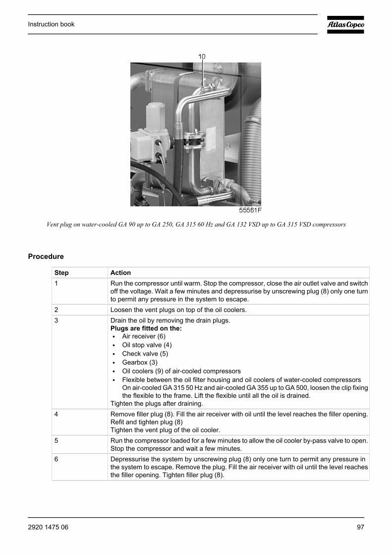
Vent plug on water-cooled GA 90 up to GA 250, GA 315 60 Hz and GA 132 VSD up to GA 315 VSD compressors
Procedure
Step Action1 Run the compressor until warm. Stop the compressor, close the air outlet valve and switch
off the voltage. Wait a few minutes and depressurise by unscrewing plug (8) only one turnto permit any pressure in the system to escape.
2 Loosen the vent plugs on top of the oil coolers.3 Drain the oil by removing the drain plugs.
Plugs are fitted on the:• Air receiver (6)• Oil stop valve (4)• Check valve (5)• Gearbox (3)• Oil coolers (9) of air-cooled compressors• Flexible between the oil filter housing and oil coolers of water-cooled compressors
On air-cooled GA 315 50 Hz and air-cooled GA 355 up to GA 500, loosen the clip fixingthe flexible to the frame. Lift the flexible until all the oil is drained.
Tighten the plugs after draining.4 Remove filler plug (8). Fill the air receiver with oil until the level reaches the filler opening.
Refit and tighten plug (8)Tighten the vent plug of the oil cooler.
5 Run the compressor loaded for a few minutes to allow the oil cooler by-pass valve to open.Stop the compressor and wait a few minutes.
6 Depressurise the system by unscrewing plug (8) only one turn to permit any pressure inthe system to escape. Remove the plug. Fill the air receiver with oil until the level reachesthe filler opening. Tighten filler plug (8).
Instruction book
2920 1475 06 97

Step Action7 After carrying out all service actions in the relevant “Service Plan”, reset the service
warning as follows:• Press the “Menu” key (3).• Press key (1) until “Service” is followed by an arrow pointing to the right. Activate the
menu by pressing key (2).• Press key (1) until the related “Service Plan” is followed by an arrow pointing to the
right and activate by pressing key (2).• Press the “Reset” key (3); the timer is reset to 0.
6.5 Oil filter change
Warning
Stop the compressor and switch off the voltage. The operator must apply all relevant Safetyprecautions.
Control panel
Control panel, MkIII regulator
Instruction book
98 2920 1475 06
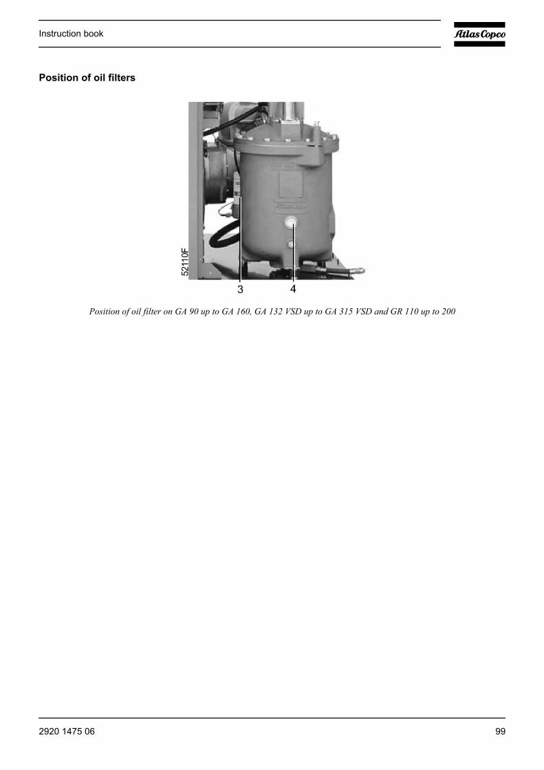
Position of oil filters
Position of oil filter on GA 90 up to GA 160, GA 132 VSD up to GA 315 VSD and GR 110 up to 200
Instruction book
2920 1475 06 99
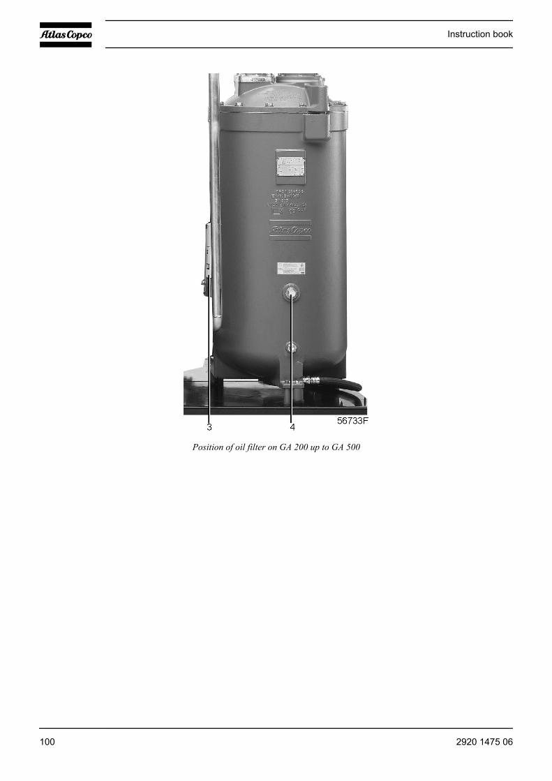
Position of oil filter on GA 200 up to GA 500
Instruction book
100 2920 1475 06

Procedure
Step Action1 Stop the compressor, close the air outlet valve and switch off the voltage. Wait a few
minutes and depressurise by unscrewing plug (4) only one turn to permit any pressure inthe system to escape.
2 Use an oil pan to avoid possible oil spillage. Unscrew oil filters (3) only one turn and waita few minutes to let the oil of the filter flow back into the oil separator. Remove the oil filters.
3 Clean the filter seats on the manifold. Oil the gaskets of the new filters and screw the filtersinto place until the gaskets contact their seats. Then tighten by hand.
4 Tighten plug (4).5 Reset the message and service timer:
• Press the “Menu” key (3).• Press key (1) until “Service” is followed by an arrow pointing to the right. Activate the
menu by pressing key (2).• Press key (1) until “Oil filter” is followed by an arrow pointing to the right. Activate the
menu by pressing key (2).• Press the “Reset” key (3); the timer is reset to 0.
6.6 Storage after installation
Procedure
Run the compressor, e.g. twice a week, until warm. Load and unload the compressor a few times to operatethe components of the unloading/loading system.
If the compressor is going to be stored without running from time to time, protectivemeasures must be taken. Consult the Atlas Copco Customer Centre.
6.7 Service kits
General
Service kits comprise all parts needed for servicing components and offer the benefits of genuine Atlas Copcoparts while keeping the maintenance budget low. All service kits are indicated in the relevant Parts Lists.
Atlas Copco Roto-Inject Fluid
Roto-Inject Fluid can be ordered in the following quantities:
• 20-litre can: 2901 0522 00• 209-litre drum: 2901 0045 01
See the section Oil specifications.
Instruction book
2920 1475 06 101
Atlas Copco Roto-Xtend Duty Fluid
Roto-Xtend Duty Fluid can be ordered in the following quantities:
• 5-litre can: 2901 1700 00• 20-litre can: 2901 1701 00• 209-litre drum: 2901 1702 00
See Oil specifications.
Instruction book
102 2920 1475 06
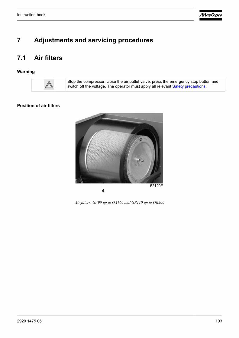
7 Adjustments and servicing procedures
7.1 Air filters
Warning
Stop the compressor, close the air outlet valve, press the emergency stop button andswitch off the voltage. The operator must apply all relevant Safety precautions.
Position of air filters
Air filters, GA90 up to GA160 and GR110 up to GR200
Instruction book
2920 1475 06 103
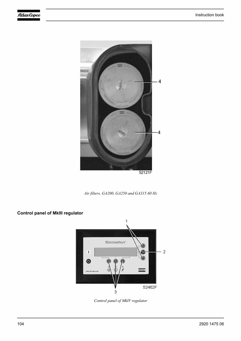
Air filters, GA200, GA250 and GA315 60 Hz
Control panel of MkIII regulator
Control panel of MkIV regulator
Instruction book
104 2920 1475 06

Procedure
Step Action1 Remove the filter elements (4).2 Fit the new filter elements (4).3 Reset the message and service timer:
• Press the “Menu” key (3).• Press key (1) until “Service” is followed by an arrow pointing to the right. Activate the
menu by pressing key (2).• Press key (1) until “Air filters” is followed by an arrow pointing to the right. Activate the
menu by pressing key (2).• Press “Reset” key (3); the timer is reset to 0.
7.2 Coolers
Warning
Stop the compressor, press the emergency stop button and switch off the voltage. Theoperator must apply all relevant Safety precautions.
Procedure
Cooler block of air-cooled GA 90 up to GA 250, GA 315 60 Hz and GR compressors
Instruction book
2920 1475 06 105
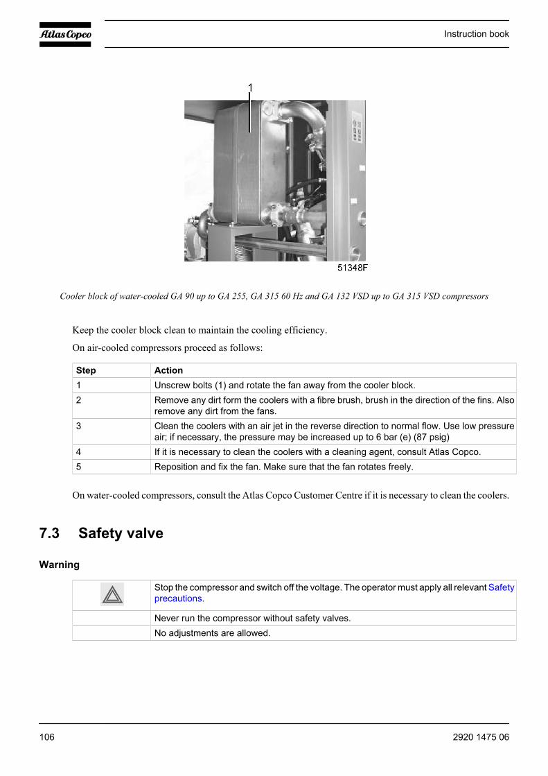
Cooler block of water-cooled GA 90 up to GA 255, GA 315 60 Hz and GA 132 VSD up to GA 315 VSD compressors
Keep the cooler block clean to maintain the cooling efficiency.
On air-cooled compressors proceed as follows:
Step Action1 Unscrew bolts (1) and rotate the fan away from the cooler block.2 Remove any dirt form the coolers with a fibre brush, brush in the direction of the fins. Also
remove any dirt from the fans.3 Clean the coolers with an air jet in the reverse direction to normal flow. Use low pressure
air; if necessary, the pressure may be increased up to 6 bar (e) (87 psig)4 If it is necessary to clean the coolers with a cleaning agent, consult Atlas Copco.5 Reposition and fix the fan. Make sure that the fan rotates freely.
On water-cooled compressors, consult the Atlas Copco Customer Centre if it is necessary to clean the coolers.
7.3 Safety valve
Warning
Stop the compressor and switch off the voltage. The operator must apply all relevant Safetyprecautions.
Never run the compressor without safety valves. No adjustments are allowed.
Instruction book
106 2920 1475 06
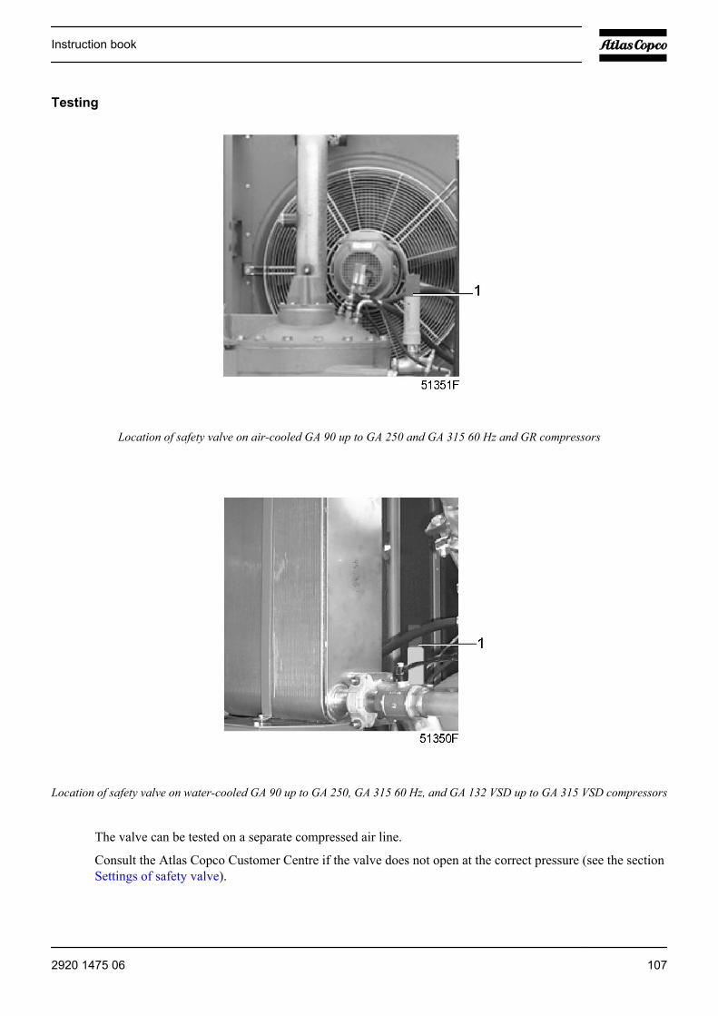
Testing
Location of safety valve on air-cooled GA 90 up to GA 250 and GA 315 60 Hz and GR compressors
Location of safety valve on water-cooled GA 90 up to GA 250, GA 315 60 Hz, and GA 132 VSD up to GA 315 VSD compressors
The valve can be tested on a separate compressed air line.
Consult the Atlas Copco Customer Centre if the valve does not open at the correct pressure (see the sectionSettings of safety valve).
Instruction book
2920 1475 06 107
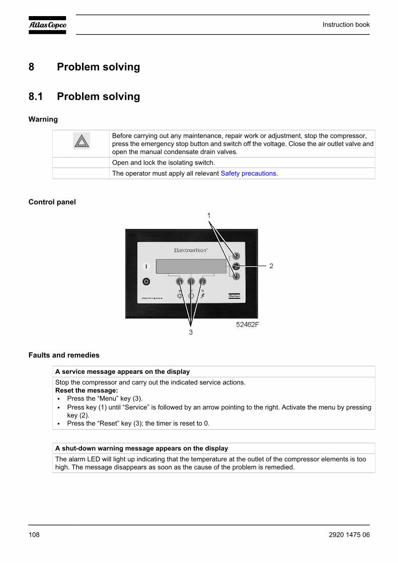
8 Problem solving
8.1 Problem solving
Warning
Before carrying out any maintenance, repair work or adjustment, stop the compressor,press the emergency stop button and switch off the voltage. Close the air outlet valve andopen the manual condensate drain valves.
Open and lock the isolating switch. The operator must apply all relevant Safety precautions.
Control panel
Faults and remedies
A service message appears on the displayStop the compressor and carry out the indicated service actions.Reset the message:• Press the “Menu” key (3).• Press key (1) until “Service” is followed by an arrow pointing to the right. Activate the menu by pressing
key (2).• Press the “Reset” key (3); the timer is reset to 0.
A shut-down warning message appears on the displayThe alarm LED will light up indicating that the temperature at the outlet of the compressor elements is toohigh. The message disappears as soon as the cause of the problem is remedied.
Instruction book
108 2920 1475 06
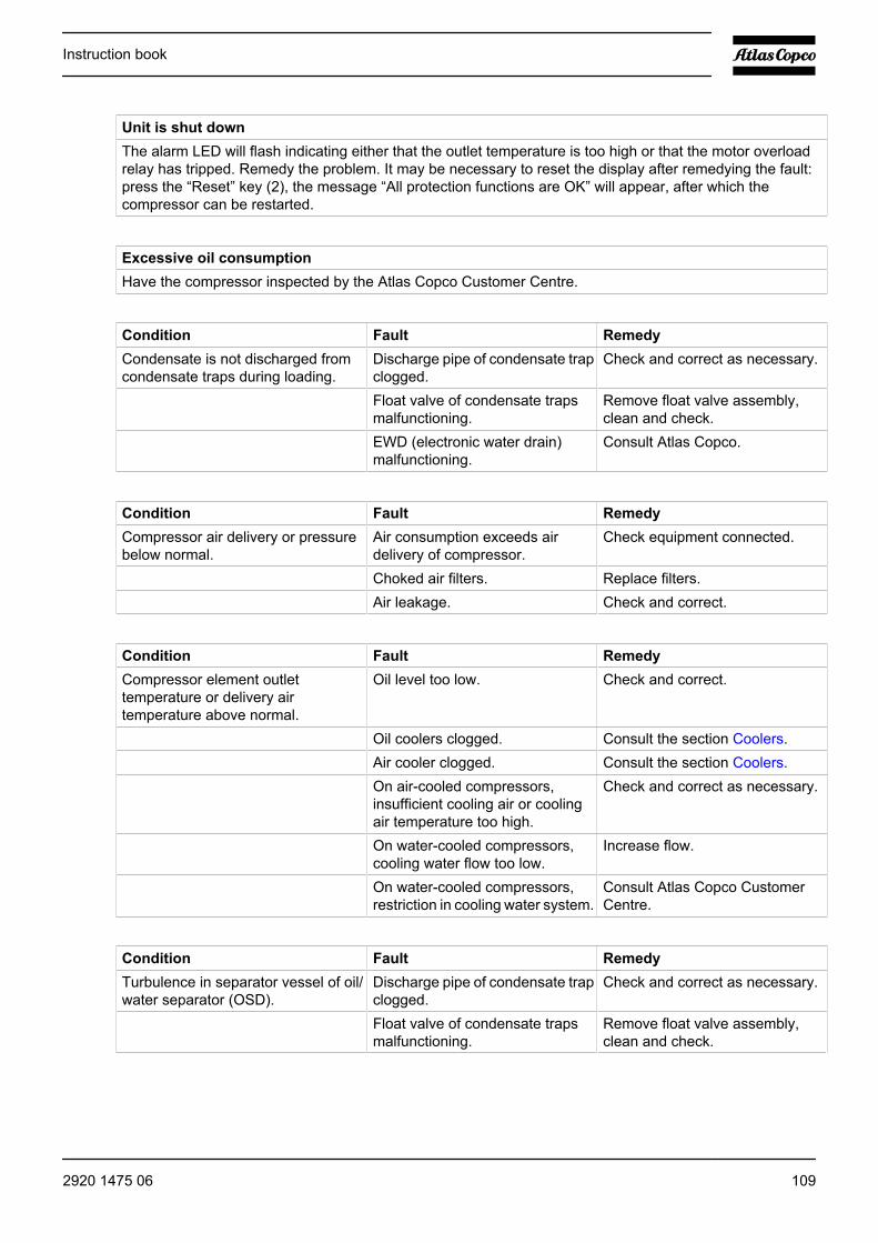
Unit is shut downThe alarm LED will flash indicating either that the outlet temperature is too high or that the motor overloadrelay has tripped. Remedy the problem. It may be necessary to reset the display after remedying the fault:press the “Reset” key (2), the message “All protection functions are OK” will appear, after which thecompressor can be restarted.
Excessive oil consumptionHave the compressor inspected by the Atlas Copco Customer Centre.
Condition Fault RemedyCondensate is not discharged fromcondensate traps during loading.
Discharge pipe of condensate trapclogged.
Check and correct as necessary.
Float valve of condensate trapsmalfunctioning.
Remove float valve assembly,clean and check.
EWD (electronic water drain)malfunctioning.
Consult Atlas Copco.
Condition Fault RemedyCompressor air delivery or pressurebelow normal.
Air consumption exceeds airdelivery of compressor.
Check equipment connected.
Choked air filters. Replace filters.Air leakage. Check and correct.
Condition Fault RemedyCompressor element outlettemperature or delivery airtemperature above normal.
Oil level too low. Check and correct.
Oil coolers clogged. Consult the section Coolers. Air cooler clogged. Consult the section Coolers. On air-cooled compressors,
insufficient cooling air or coolingair temperature too high.
Check and correct as necessary.
On water-cooled compressors,cooling water flow too low.
Increase flow.
On water-cooled compressors,restriction in cooling water system.
Consult Atlas Copco CustomerCentre.
Condition Fault RemedyTurbulence in separator vessel of oil/water separator (OSD).
Discharge pipe of condensate trapclogged.
Check and correct as necessary.
Float valve of condensate trapsmalfunctioning.
Remove float valve assembly,clean and check.
Instruction book
2920 1475 06 109
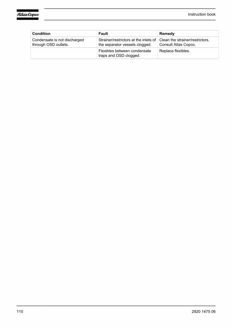
Condition Fault RemedyCondensate is not dischargedthrough OSD outlets.
Strainer/restrictors at the inlets ofthe separator vessels clogged.
Clean the strainer/restrictors.Consult Atlas Copco.
Flexibles between condensatetraps and OSD clogged.
Replace flexibles.
Instruction book
110 2920 1475 06

9 Technical data
9.1 Readings on display
Important
The readings are valid when operating under reference conditions. See the sectionReference conditions
Normally the main display is shown (see the section Function keys), indicating theactual air outlet pressure and the actual compressor status. The arrow down keyallows the operator to call up other information such as actually measuredpressures and temperatures.
Important readings
Compressor outlet pressure bar(e) (psig) Depends on programmedunloading and loadingpressures
Pressure drop over air filters bar Below 0.05Pressure drop over air filters psi Below 0.73Pressure difference over oil separator bar Below 0.8Pressure difference over oil separator psi Below 12Oil injection pressure at the compressor elements bar(e) (psig) Depends on programmed
unloading and loadingpressures
Compressor outlet temperature, air-cooled Pack compressors ˚C Approx. 29Compressor outlet temperature, air-cooled Pack compressors ˚F Approx. 84Compressor outlet temperature, air-cooled Full-Featurecompressors
˚C Approx. 26
Compressor outlet temperature, air-cooled Full-Featurecompressors
˚F Approx. 79
Compressor outlet temperature, water-cooled GA90 up toGA250 and GA315 60 Hz Pack compressors
˚C Approx. 25
Compressor outlet temperature, water-cooled GA90 up toGA250 and GA315 60 Hz Pack compressors
˚F Approx. 77
Compressor outlet temperature, water-cooled Full-Featurecompressors
˚C Approx. 22
Compressor outlet temperature, water-cooled Full-Featurecompressors
˚F Approx. 72
Compressor element outlet temperature, GA90 up to GA250and GA315 60 Hz compressors
˚C Between 55 and 100
Compressor element outlet temperature, GA90 up to GA250and GA315 60 Hz compressors
˚F Between 131 and 212
Cooling air inlet temperature ˚C Below 40Cooling air inlet temperature ˚F Below 104
Instruction book
2920 1475 06 111

Cooling water temperature, GA90 up to GA250 and GA315 60Hz and GR compressors
˚C Below 50
Cooling water temperature, GA90 up to GA250 and GA315 60Hz and GR compressors
˚F Below 122
Pressure dew-point ˚C Approx. 3Pressure dew-point ˚F Approx. 37Pressure drop over DD filter bar Below 0.35Pressure drop over DD filter psi Below 5
9.2 Reference conditions
Reference conditions
Absolute inlet pressure bar(a) 1Absolute inlet pressure psi 14.5Relative air humidity % 0Air inlet temperature ˚C 20Air inlet temperature ˚F 68Nominal working pressure See Compressor dataCooling water inlet temperature ˚C 20Cooling water inlet temperature ˚F 68
9.3 Limits
Limits
Maximum air inlet/ambient temperature ˚C 40Maximum air inlet/ambient temperature ˚F 104Minimum air inlet/ambient temperature ˚C 0Minimum air inletambient temperature ˚F 32Maximum cooling air temperature ˚C 40Maximum cooling air temperature ˚F 104Minimum cooling air temperature ˚C 0Minimum cooling air temperature ˚F 32Maximum working pressure See section Compressor
dataMaximum cooling water inlet temperature ˚C 40Maximum cooling water inlet temperature ˚F 104Maximum cooling water outlet temperature (open systems) ˚C 50Maximum cooling water outlet temperature (open systems) ˚F 122Maximum cooling water outlet temperature (recirculatingsystems)
˚C 60
Instruction book
112 2920 1475 06

Maximum cooling water outlet temperature (recirculatingsystems)
˚F 140
Maximum cooling water inlet pressure bar(e) 10Maximum cooling water inlet pressure psig 145
9.4 Settings of safety valve
Compressor type SettingFor GA compressors with a maximum working pressure of 7.5 or 8.5 bar 11 bar (e)For GA compressors with a maximum working pressure of 109 or 123 psi 160 psigFor GA compressors with a maximum working pressure of 6.9, 8.6, 10, 10.4, 13 or13.8 bar
15 bar (e)
For GA compressors with a maximum working pressure of 100, 125, 145, 150, 188or 200 psi
217 psig
9.5 Settings for overload relay and fuses
50 Hz IEC compressors with ABB motors
GA 90 up to GA 250 and GR 110 up to GR 200
Compressortype
Supplyvoltage (V)
Overload relay(A)
Fuses Class gL/gG (Type 2) (A)2X3 fuses2X3 cables tocontactor
Fuses Class gL/gG (Type 2) (A)3 fuses2X3 cables tocontactor
Fuses Class gL/gG (Type 2) (A)3 fuses3 cables tocontactor(bridges to beinstalled bycustomer)
GA 90 230 197 2x (3x250) 3x400 --GA 90 400 110 2x (3x160) 3x224 --GA 90 500 87 2x (3x125) -- 3x200GA/GR 110 230 229 2x (3x300) -- --GA/GR 110 400 134 2x (3x200) 3x300 --GA/GR 110 500 107 2x (3x160) -- 3x224GA/GR 132 230 270 2x (3x355) -- --GA/GR 132 400 161 2x (3x224) 2x315 --GA/GR 132 500 128 2x (3x200 3x250 --GA/GR 160 230 345 2x (3x500) -- --GA/GR 160 400 191 2x (3x250) 3x400 --GA/GR 160 500 154 2x (3x200) 3x300 --GA/GR 200 400 233 2x (3x315) -- --GA/GR 200 500 186 2x (3x250) 3x400 --
Instruction book
2920 1475 06 113

Compressortype
Supplyvoltage (V)
Overload relay(A)
Fuses Class gL/gG (Type 2) (A)2X3 fuses2X3 cables tocontactor
Fuses Class gL/gG (Type 2) (A)3 fuses2X3 cables tocontactor
Fuses Class gL/gG (Type 2) (A)3 fuses3 cables tocontactor(bridges to beinstalled bycustomer)
GA 250 400 289 2x (3x355) -- --GA 250 500 234 2x (3x300) -- --
60Hz IEC compressors with ABB motors
GA 90 up to GA 315 and GR 110 up to GR 200
Compressortype
Supplyvoltage (V)
Overload relay(A)
Fuses Class gL/gG (Type 2) (A)2X3 fuses2X3 cables tocontactor
Fuses Class gL/gG (Type 1) (A)3 fuses2X3 cables tocontactor
Fuses Class gL/gG (Type 1) (A)3 fuses3 cables tocontactor(bridges to beinstalled bycustomer)
GA 90 220-230 208 2x (3x300) -- --GA 90 380 122 2x (3x160) 3x250 --GA 90 440-460 104 2x (3x160) -- 3x224GA/GR 110 220-230 257 2x (3x355) -- --GA/GR 110 380 149 2x (3x200) 3x300 --GA/GR 110 440-460 129 2x (3x160) 3x300 --GA/GR 160 380 195 2x (3x250) 3x400 --GA/GR 160 440-460 169 2x (3x224) -- --GA/GR 200 380 242 2x (3x355) -- --GA/GR 200 440-460 204 2x (3x300) -- --GA 250 380 284 2x (3x400) -- --GA 250 440-460 246 2x (3x315) -- --GA 315 380 319 2x (3x400) -- --GA 315 440-460 278 2x (3x355) -- --
60 Hz CSA/UL compressors with Siemens or Weg motor
GA 90 up to GA 315 and GR 110 up to GR 200
Instruction book
114 2920 1475 06
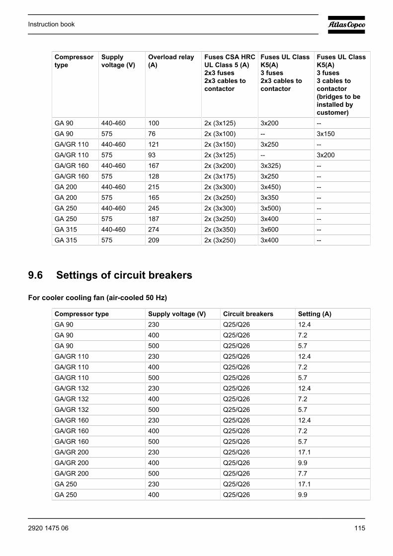
Compressortype
Supplyvoltage (V)
Overload relay(A)
Fuses CSA HRCUL Class 5 (A)2x3 fuses2x3 cables tocontactor
Fuses UL ClassK5(A)3 fuses2x3 cables tocontactor
Fuses UL ClassK5(A)3 fuses3 cables tocontactor(bridges to beinstalled bycustomer)
GA 90 440-460 100 2x (3x125) 3x200 --GA 90 575 76 2x (3x100) -- 3x150GA/GR 110 440-460 121 2x (3x150) 3x250 --GA/GR 110 575 93 2x (3x125) -- 3x200GA/GR 160 440-460 167 2x (3x200) 3x325) --GA/GR 160 575 128 2x (3x175) 3x250 --GA 200 440-460 215 2x (3x300) 3x450) --GA 200 575 165 2x (3x250) 3x350 --GA 250 440-460 245 2x (3x300) 3x500) --GA 250 575 187 2x (3x250) 3x400 --GA 315 440-460 274 2x (3x350) 3x600 --GA 315 575 209 2x (3x250) 3x400 --
9.6 Settings of circuit breakers
For cooler cooling fan (air-cooled 50 Hz)
Compressor type Supply voltage (V) Circuit breakers Setting (A)GA 90 230 Q25/Q26 12.4GA 90 400 Q25/Q26 7.2GA 90 500 Q25/Q26 5.7GA/GR 110 230 Q25/Q26 12.4GA/GR 110 400 Q25/Q26 7.2GA/GR 110 500 Q25/Q26 5.7GA/GR 132 230 Q25/Q26 12.4GA/GR 132 400 Q25/Q26 7.2GA/GR 132 500 Q25/Q26 5.7GA/GR 160 230 Q25/Q26 12.4GA/GR 160 400 Q25/Q26 7.2GA/GR 160 500 Q25/Q26 5.7GA/GR 200 230 Q25/Q26 17.1GA/GR 200 400 Q25/Q26 9.9GA/GR 200 500 Q25/Q26 7.7GA 250 230 Q25/Q26 17.1GA 250 400 Q25/Q26 9.9
Instruction book
2920 1475 06 115
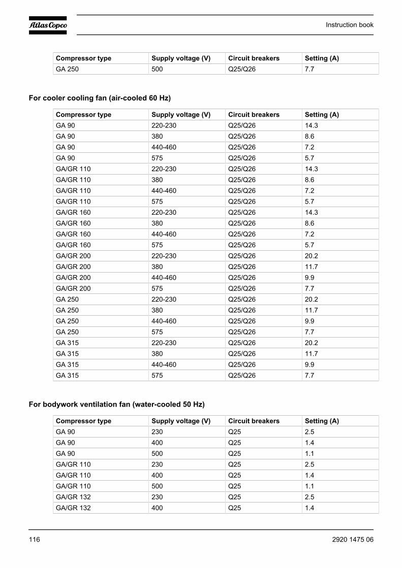
Compressor type Supply voltage (V) Circuit breakers Setting (A)GA 250 500 Q25/Q26 7.7
For cooler cooling fan (air-cooled 60 Hz)
Compressor type Supply voltage (V) Circuit breakers Setting (A)GA 90 220-230 Q25/Q26 14.3GA 90 380 Q25/Q26 8.6GA 90 440-460 Q25/Q26 7.2GA 90 575 Q25/Q26 5.7GA/GR 110 220-230 Q25/Q26 14.3GA/GR 110 380 Q25/Q26 8.6GA/GR 110 440-460 Q25/Q26 7.2GA/GR 110 575 Q25/Q26 5.7GA/GR 160 220-230 Q25/Q26 14.3GA/GR 160 380 Q25/Q26 8.6GA/GR 160 440-460 Q25/Q26 7.2GA/GR 160 575 Q25/Q26 5.7GA/GR 200 220-230 Q25/Q26 20.2GA/GR 200 380 Q25/Q26 11.7GA/GR 200 440-460 Q25/Q26 9.9GA/GR 200 575 Q25/Q26 7.7GA 250 220-230 Q25/Q26 20.2GA 250 380 Q25/Q26 11.7GA 250 440-460 Q25/Q26 9.9GA 250 575 Q25/Q26 7.7GA 315 220-230 Q25/Q26 20.2GA 315 380 Q25/Q26 11.7GA 315 440-460 Q25/Q26 9.9GA 315 575 Q25/Q26 7.7
For bodywork ventilation fan (water-cooled 50 Hz)
Compressor type Supply voltage (V) Circuit breakers Setting (A)GA 90 230 Q25 2.5GA 90 400 Q25 1.4GA 90 500 Q25 1.1GA/GR 110 230 Q25 2.5GA/GR 110 400 Q25 1.4GA/GR 110 500 Q25 1.1GA/GR 132 230 Q25 2.5GA/GR 132 400 Q25 1.4
Instruction book
116 2920 1475 06
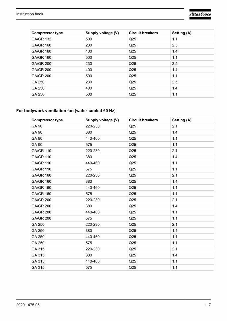
Compressor type Supply voltage (V) Circuit breakers Setting (A)GA/GR 132 500 Q25 1.1GA/GR 160 230 Q25 2.5GA/GR 160 400 Q25 1.4GA/GR 160 500 Q25 1.1GA/GR 200 230 Q25 2.5GA/GR 200 400 Q25 1.4GA/GR 200 500 Q25 1.1GA 250 230 Q25 2.5GA 250 400 Q25 1.4GA 250 500 Q25 1.1
For bodywork ventilation fan (water-cooled 60 Hz)
Compressor type Supply voltage (V) Circuit breakers Setting (A)GA 90 220-230 Q25 2.1GA 90 380 Q25 1.4GA 90 440-460 Q25 1.1GA 90 575 Q25 1.1GA/GR 110 220-230 Q25 2.1GA/GR 110 380 Q25 1.4GA/GR 110 440-460 Q25 1.1GA/GR 110 575 Q25 1.1GA/GR 160 220-230 Q25 2.1GA/GR 160 380 Q25 1.4GA/GR 160 440-460 Q25 1.1GA/GR 160 575 Q25 1.1GA/GR 200 220-230 Q25 2.1GA/GR 200 380 Q25 1.4GA/GR 200 440-460 Q25 1.1GA/GR 200 575 Q25 1.1GA 250 220-230 Q25 2.1GA 250 380 Q25 1.4GA 250 440-460 Q25 1.1GA 250 575 Q25 1.1GA 315 220-230 Q25 2.1GA 315 380 Q25 1.4GA 315 440-460 Q25 1.1GA 315 575 Q25 1.1
Instruction book
2920 1475 06 117

For dryer motor (50 Hz)
Compressor type Supply voltage (V) Circuit breakers Setting (A)GA 90 230 Q40 19GA 90 400 Q40 11GA 90 500 Q40 9GA/GR 110 230 Q40 19GA/GR 110 400 Q40 11GA/GR 110 500 Q40 9GA/GR 132 230 Q40 28GA/GR 132 400 Q40 16GA/GR 132 500 Q40 13GA/GR 160 230 Q40 28GA/GR 160 400 Q40 16GA/GR 160 500 Q40 13GA 200 400 Q40 27GA 200 500 Q40 22GA 250 400 Q40 27GA 250 500 Q40 22
For dryer motor (60 Hz)
Compressor type Supply voltage (V) Circuit breakers Setting (A)GA 90 220-230 Q40 25GA 90 380 Q40 15GA 90 440-460 Q40 13GA 90 575 Q40 10GA 110 220-230 Q40 25GA 110 380 Q40 15GA 110 440-460 Q40 13GA 110 575 Q40 10GA/GR 160 380 Q40 22GA/GR 160 440-460 Q40 19GA/GR 160 575 Q40 15GA 200 380 Q40 38GA 200 440-460 Q40 33GA 200 575 Q40 25GA 250 380 Q40 38GA 250 440-460 Q40 33GA 250 575 Q40 25GA 315 380 Q40 38GA 315 440-460 Q40 33
Instruction book
118 2920 1475 06
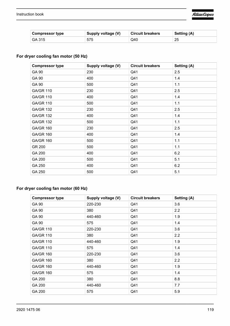
Compressor type Supply voltage (V) Circuit breakers Setting (A)GA 315 575 Q40 25
For dryer cooling fan motor (50 Hz)
Compressor type Supply voltage (V) Circuit breakers Setting (A)GA 90 230 Q41 2.5GA 90 400 Q41 1.4GA 90 500 Q41 1.1GA/GR 110 230 Q41 2.5GA/GR 110 400 Q41 1.4GA/GR 110 500 Q41 1.1GA/GR 132 230 Q41 2.5GA/GR 132 400 Q41 1.4GA/GR 132 500 Q41 1.1GA/GR 160 230 Q41 2.5GA/GR 160 400 Q41 1.4GA/GR 160 500 Q41 1.1GR 200 500 Q41 1.1GA 200 400 Q41 6.2GA 200 500 Q41 5.1GA 250 400 Q41 6.2GA 250 500 Q41 5.1
For dryer cooling fan motor (60 Hz)
Compressor type Supply voltage (V) Circuit breakers Setting (A)GA 90 220-230 Q41 3.6GA 90 380 Q41 2.2GA 90 440-460 Q41 1.9GA 90 575 Q41 1.4GA/GR 110 220-230 Q41 3.6GA/GR 110 380 Q41 2.2GA/GR 110 440-460 Q41 1.9GA/GR 110 575 Q41 1.4GA/GR 160 220-230 Q41 3.6GA/GR 160 380 Q41 2.2GA/GR 160 440-460 Q41 1.9GA/GR 160 575 Q41 1.4GA 200 380 Q41 8.8GA 200 440-460 Q41 7.7GA 200 575 Q41 5.9
Instruction book
2920 1475 06 119
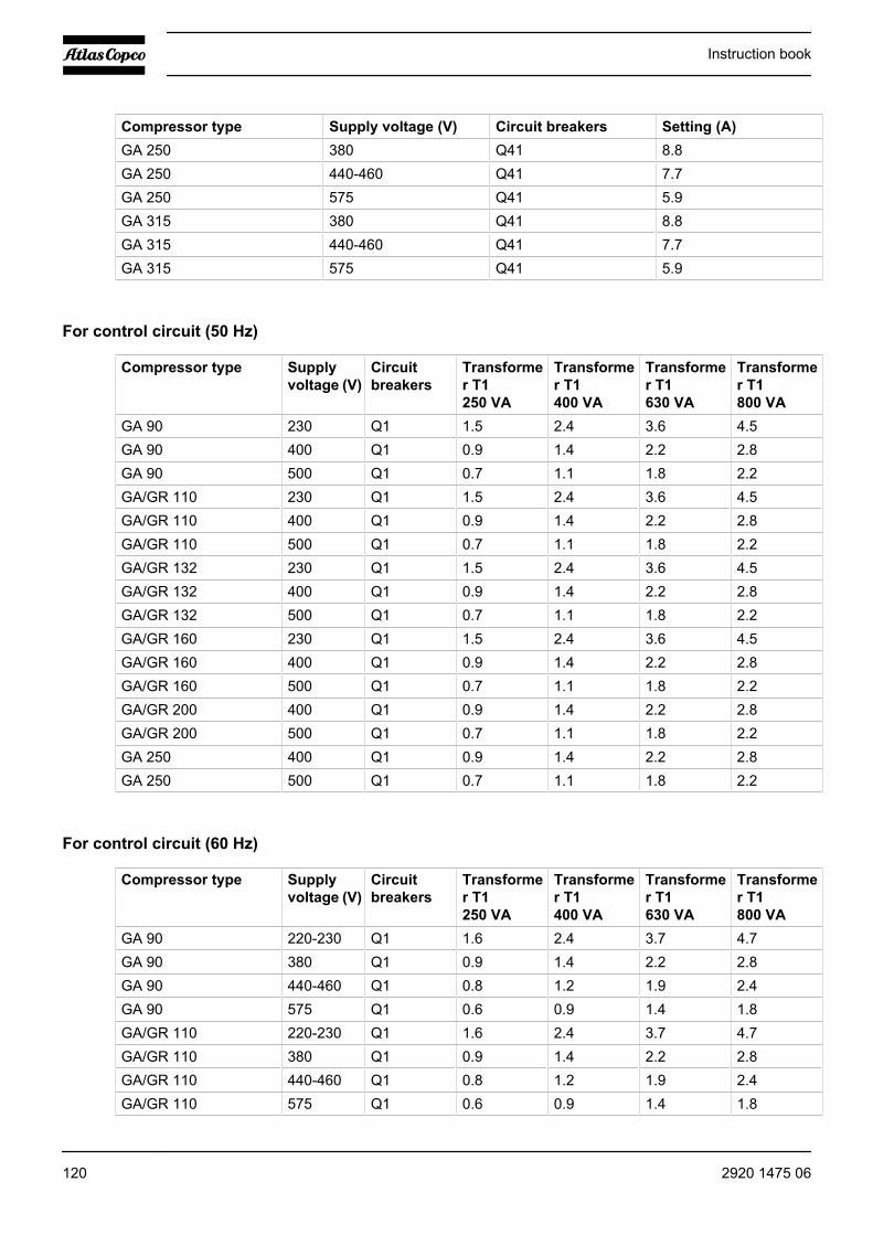
Compressor type Supply voltage (V) Circuit breakers Setting (A)GA 250 380 Q41 8.8GA 250 440-460 Q41 7.7GA 250 575 Q41 5.9GA 315 380 Q41 8.8GA 315 440-460 Q41 7.7GA 315 575 Q41 5.9
For control circuit (50 Hz)
Compressor type Supplyvoltage (V)
Circuitbreakers
Transformer T1250 VA
Transformer T1400 VA
Transformer T1630 VA
Transformer T1800 VA
GA 90 230 Q1 1.5 2.4 3.6 4.5GA 90 400 Q1 0.9 1.4 2.2 2.8GA 90 500 Q1 0.7 1.1 1.8 2.2GA/GR 110 230 Q1 1.5 2.4 3.6 4.5GA/GR 110 400 Q1 0.9 1.4 2.2 2.8GA/GR 110 500 Q1 0.7 1.1 1.8 2.2GA/GR 132 230 Q1 1.5 2.4 3.6 4.5GA/GR 132 400 Q1 0.9 1.4 2.2 2.8GA/GR 132 500 Q1 0.7 1.1 1.8 2.2GA/GR 160 230 Q1 1.5 2.4 3.6 4.5GA/GR 160 400 Q1 0.9 1.4 2.2 2.8GA/GR 160 500 Q1 0.7 1.1 1.8 2.2GA/GR 200 400 Q1 0.9 1.4 2.2 2.8GA/GR 200 500 Q1 0.7 1.1 1.8 2.2GA 250 400 Q1 0.9 1.4 2.2 2.8GA 250 500 Q1 0.7 1.1 1.8 2.2
For control circuit (60 Hz)
Compressor type Supplyvoltage (V)
Circuitbreakers
Transformer T1250 VA
Transformer T1400 VA
Transformer T1630 VA
Transformer T1800 VA
GA 90 220-230 Q1 1.6 2.4 3.7 4.7GA 90 380 Q1 0.9 1.4 2.2 2.8GA 90 440-460 Q1 0.8 1.2 1.9 2.4GA 90 575 Q1 0.6 0.9 1.4 1.8GA/GR 110 220-230 Q1 1.6 2.4 3.7 4.7GA/GR 110 380 Q1 0.9 1.4 2.2 2.8GA/GR 110 440-460 Q1 0.8 1.2 1.9 2.4GA/GR 110 575 Q1 0.6 0.9 1.4 1.8
Instruction book
120 2920 1475 06
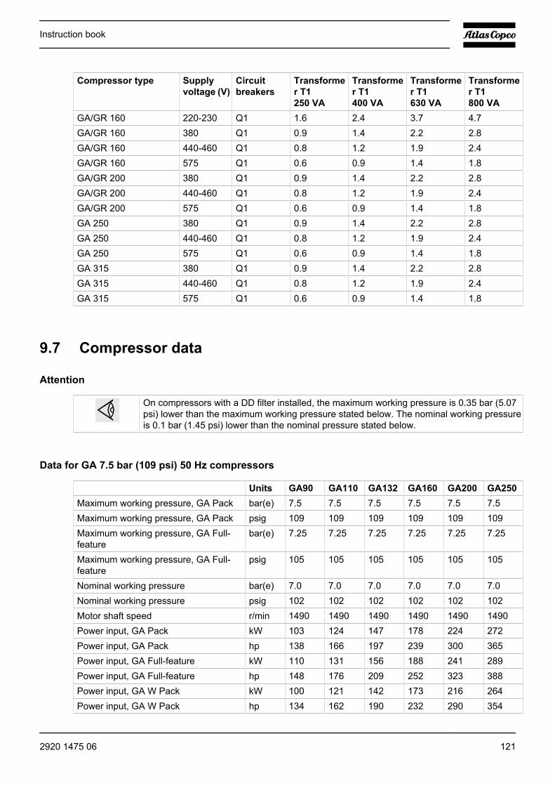
Compressor type Supplyvoltage (V)
Circuitbreakers
Transformer T1250 VA
Transformer T1400 VA
Transformer T1630 VA
Transformer T1800 VA
GA/GR 160 220-230 Q1 1.6 2.4 3.7 4.7GA/GR 160 380 Q1 0.9 1.4 2.2 2.8GA/GR 160 440-460 Q1 0.8 1.2 1.9 2.4GA/GR 160 575 Q1 0.6 0.9 1.4 1.8GA/GR 200 380 Q1 0.9 1.4 2.2 2.8GA/GR 200 440-460 Q1 0.8 1.2 1.9 2.4GA/GR 200 575 Q1 0.6 0.9 1.4 1.8GA 250 380 Q1 0.9 1.4 2.2 2.8GA 250 440-460 Q1 0.8 1.2 1.9 2.4GA 250 575 Q1 0.6 0.9 1.4 1.8GA 315 380 Q1 0.9 1.4 2.2 2.8GA 315 440-460 Q1 0.8 1.2 1.9 2.4GA 315 575 Q1 0.6 0.9 1.4 1.8
9.7 Compressor data
Attention
On compressors with a DD filter installed, the maximum working pressure is 0.35 bar (5.07psi) lower than the maximum working pressure stated below. The nominal working pressureis 0.1 bar (1.45 psi) lower than the nominal pressure stated below.
Data for GA 7.5 bar (109 psi) 50 Hz compressors
Units GA90 GA110 GA132 GA160 GA200 GA250Maximum working pressure, GA Pack bar(e) 7.5 7.5 7.5 7.5 7.5 7.5Maximum working pressure, GA Pack psig 109 109 109 109 109 109Maximum working pressure, GA Full-feature
bar(e) 7.25 7.25 7.25 7.25 7.25 7.25
Maximum working pressure, GA Full-feature
psig 105 105 105 105 105 105
Nominal working pressure bar(e) 7.0 7.0 7.0 7.0 7.0 7.0Nominal working pressure psig 102 102 102 102 102 102Motor shaft speed r/min 1490 1490 1490 1490 1490 1490Power input, GA Pack kW 103 124 147 178 224 272Power input, GA Pack hp 138 166 197 239 300 365Power input, GA Full-feature kW 110 131 156 188 241 289Power input, GA Full-feature hp 148 176 209 252 323 388Power input, GA W Pack kW 100 121 142 173 216 264Power input, GA W Pack hp 134 162 190 232 290 354
Instruction book
2920 1475 06 121
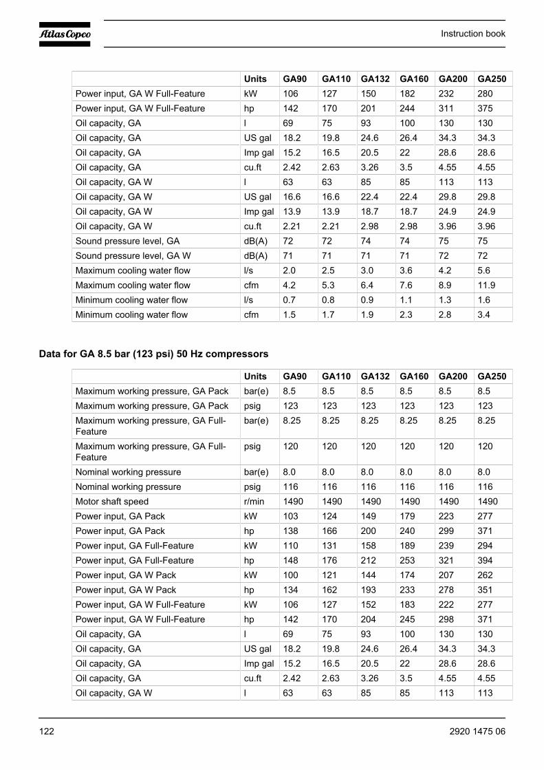
Units GA90 GA110 GA132 GA160 GA200 GA250Power input, GA W Full-Feature kW 106 127 150 182 232 280Power input, GA W Full-Feature hp 142 170 201 244 311 375Oil capacity, GA l 69 75 93 100 130 130Oil capacity, GA US gal 18.2 19.8 24.6 26.4 34.3 34.3Oil capacity, GA Imp gal 15.2 16.5 20.5 22 28.6 28.6Oil capacity, GA cu.ft 2.42 2.63 3.26 3.5 4.55 4.55Oil capacity, GA W l 63 63 85 85 113 113Oil capacity, GA W US gal 16.6 16.6 22.4 22.4 29.8 29.8Oil capacity, GA W Imp gal 13.9 13.9 18.7 18.7 24.9 24.9Oil capacity, GA W cu.ft 2.21 2.21 2.98 2.98 3.96 3.96Sound pressure level, GA dB(A) 72 72 74 74 75 75Sound pressure level, GA W dB(A) 71 71 71 71 72 72Maximum cooling water flow l/s 2.0 2.5 3.0 3.6 4.2 5.6Maximum cooling water flow cfm 4.2 5.3 6.4 7.6 8.9 11.9Minimum cooling water flow l/s 0.7 0.8 0.9 1.1 1.3 1.6Minimum cooling water flow cfm 1.5 1.7 1.9 2.3 2.8 3.4
Data for GA 8.5 bar (123 psi) 50 Hz compressors
Units GA90 GA110 GA132 GA160 GA200 GA250Maximum working pressure, GA Pack bar(e) 8.5 8.5 8.5 8.5 8.5 8.5Maximum working pressure, GA Pack psig 123 123 123 123 123 123Maximum working pressure, GA Full-Feature
bar(e) 8.25 8.25 8.25 8.25 8.25 8.25
Maximum working pressure, GA Full-Feature
psig 120 120 120 120 120 120
Nominal working pressure bar(e) 8.0 8.0 8.0 8.0 8.0 8.0Nominal working pressure psig 116 116 116 116 116 116Motor shaft speed r/min 1490 1490 1490 1490 1490 1490Power input, GA Pack kW 103 124 149 179 223 277Power input, GA Pack hp 138 166 200 240 299 371Power input, GA Full-Feature kW 110 131 158 189 239 294Power input, GA Full-Feature hp 148 176 212 253 321 394Power input, GA W Pack kW 100 121 144 174 207 262Power input, GA W Pack hp 134 162 193 233 278 351Power input, GA W Full-Feature kW 106 127 152 183 222 277Power input, GA W Full-Feature hp 142 170 204 245 298 371Oil capacity, GA l 69 75 93 100 130 130Oil capacity, GA US gal 18.2 19.8 24.6 26.4 34.3 34.3Oil capacity, GA Imp gal 15.2 16.5 20.5 22 28.6 28.6Oil capacity, GA cu.ft 2.42 2.63 3.26 3.5 4.55 4.55Oil capacity, GA W l 63 63 85 85 113 113
Instruction book
122 2920 1475 06

Units GA90 GA110 GA132 GA160 GA200 GA250Oil capacity, GA W US gal 16.6 16.6 22.4 22.4 29.8 29.8Oil capacity, GA W Imp gal 13.9 13.9 18.7 18.7 24.9 24.9Oil capacity, GA W cu.ft 2.21 2.21 2.98 2.98 3.96 3.96Sound pressure level, GA dB(A) 72 72 74 74 75 75Sound pressure level, GA W dB(A) 71 71 71 71 72 72Maximum cooling water flow l/s 2.0 2.5 3.0 3.6 4.2 5.6Maximum cooling water flow cfm 4.2 5.3 6.4 7.6 8.9 11.9Minimum cooling water flow l/s 0.7 0.8 0.9 1.1 1.3 1.6Minimum cooling water flow cfm 1.5 1.7 1.9 2.3 2.8 3.4
Data for GA 10 bar (145 psi) 50 Hz compressors
Units GA90 GA110 GA132 GA160 GA200 GA250Maximum working pressure, GA Pack bar(e) 10 10 10 10 10 10Maximum working pressure, GA Pack psig 145 145 145 145 145 145Maximum working pressure, GA Full-Feature
bar(e) 9.75 9.75 9.75 9.75 9.75 9.75
Maximum working pressure, GA Full-Feature
psig 141 141 141 141 141 141
Nominal working pressure bar(e) 9.5 9.5 9.5 9.5 9.5 9.5Nominal working pressure psig 138 138 138 138 138 138Motor shaft speed r/min 1490 1490 1490 1490 1490 1490Power input, GA Pack kW 102 124 146 178 224 273Power input, GA Pack hp 137 166 196 239 300 366Power input, GA Full-Feature kW 108 131 155 187 240 290Power input, GA Full-Feature hp 145 176 208 251 322 389Power input, GA W Pack kW 99 121 141 173 216 265Power input, GA W Pack hp 133 162 189 232 290 355Power input, GA W Full-Feature kW 104 127 149 181 231 281Power input, GA W Full-Feature hp 139 170 200 243 310 377Oil capacity, GA l 69 75 93 100 130 130Oil capacity, GA US gal 18.2 19.8 24.6 26.4 34.3 34.3Oil capacity, GA Imp gal 15.2 16.5 20.5 22 28.6 28.6Oil capacity, GA cu.ft 2.42 2.63 3.26 3.5 4.55 4.55Oil capacity, GA W l 63 63 85 85 113 113Oil capacity, GA W US gal 16.6 16.6 22.4 22.4 29.8 29.8Oil capacity, GA W Imp gal 13.9 13.9 18.7 18.7 24.9 24.9Oil capacity, GA W cu.ft 2.21 2.21 2.98 2.98 3.96 3.96Sound pressure level, GA dB(A) 72 72 74 74 75 75Sound pressure level, GA W dB(A) 71 71 71 71 72 72Maximum cooling water flow l/s 2.0 2.5 3.0 3.6 4.2 5.6Maximum cooling water flow cfm 4.2 5.3 6.4 7.6 8.9 11.9
Instruction book
2920 1475 06 123
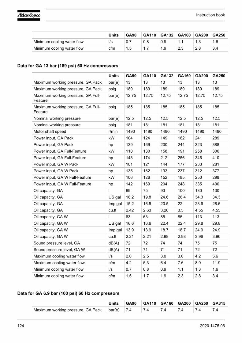
Units GA90 GA110 GA132 GA160 GA200 GA250Minimum cooling water flow l/s 0.7 0.8 0.9 1.1 1.3 1.6Minimum cooling water flow cfm 1.5 1.7 1.9 2.3 2.8 3.4
Data for GA 13 bar (189 psi) 50 Hz compressors
Units GA90 GA110 GA132 GA160 GA200 GA250Maximum working pressure, GA Pack bar(e) 13 13 13 13 13 13Maximum working pressure, GA Pack psig 189 189 189 189 189 189Maximum working pressure, GA Full-Feature
bar(e) 12.75 12.75 12.75 12.75 12.75 12.75
Maximum working pressure, GA Full-Feature
psig 185 185 185 185 185 185
Nominal working pressure bar(e) 12.5 12.5 12.5 12.5 12.5 12.5Nominal working pressure psig 181 181 181 181 181 181Motor shaft speed r/min 1490 1490 1490 1490 1490 1490Power input, GA Pack kW 104 124 149 182 241 289Power input, GA Pack hp 139 166 200 244 323 388Power input, GA Full-Feature kW 110 130 158 191 258 306Power input, GA Full-Feature hp 148 174 212 256 346 410Power input, GA W Pack kW 101 121 144 177 233 281Power input, GA W Pack hp 135 162 193 237 312 377Power input, GA W Full-Feature kW 106 126 152 185 250 298Power input, GA W Full-Feature hp 142 169 204 248 335 400Oil capacity, GA l 69 75 93 100 130 130Oil capacity, GA US gal 18.2 19.8 24.6 26.4 34.3 34.3Oil capacity, GA Imp gal 15.2 16.5 20.5 22 28.6 28.6Oil capacity, GA cu.ft 2.42 2.63 3.26 3.5 4.55 4.55Oil capacity, GA W l 63 63 85 85 113 113Oil capacity, GA W US gal 16.6 16.6 22.4 22.4 29.8 29.8Oil capacity, GA W Imp gal 13.9 13.9 18.7 18.7 24.9 24.9Oil capacity, GA W cu.ft 2.21 2.21 2.98 2.98 3.96 3.96Sound pressure level, GA dB(A) 72 72 74 74 75 75Sound pressure level, GA W dB(A) 71 71 71 71 72 72Maximum cooling water flow l/s 2.0 2.5 3.0 3.6 4.2 5.6Maximum cooling water flow cfm 4.2 5.3 6.4 7.6 8.9 11.9Minimum cooling water flow l/s 0.7 0.8 0.9 1.1 1.3 1.6Minimum cooling water flow cfm 1.5 1.7 1.9 2.3 2.8 3.4
Data for GA 6.9 bar (100 psi) 60 Hz compressors
Units GA90 GA110 GA160 GA200 GA250 GA315Maximum working pressure, GA Pack bar(e) 7.4 7.4 7.4 7.4 7.4 7.4
Instruction book
124 2920 1475 06

Units GA90 GA110 GA160 GA200 GA250 GA315Maximum working pressure, GA Pack psig 107 107 107 107 107 107Maximum working pressure, GA Full-Feature
bar(e) 7.15 7.15 7.15 7.15 7.15 7.15
Maximum working pressure, GA Full-Feature
psig 104 104 104 104 104 104
Nominal working pressure bar(e) 6.9 6.9 6.9 6.9 6.9 6.9Nominal working pressure psig 100 100 100 100 100 100Motor shaft speed r/min 1790 1790 1790 1790 1790 1790Power input, GA Pack kW 109 133 178 217 254 291Power input, GA Pack hp 146 178 239 291 341 390Power input, GA Full-Feature kW 116 140 188 234 271 309Power input, GA Full-Feature hp 156 188 252 314 363 414Power input, GA W Pack kW 105 128 171 208 245 282Power input, GA W Pack hp 141 172 229 279 329 378Power input, GA W Full-Feature kW 112 134 181 225 262 300Power input, GA W Full-Feature hp 150 180 243 302 351 402Oil capacity, GA l 69 75 100 130 130 130Oil capacity, GA US gal 18.2 19.8 26.4 34.3 34.3 34.3Oil capacity, GA Imp gal 15.2 16.5 22 28.6 28.6 28.6Oil capacity, GA cu.ft 2.42 2.63 3.5 4.55 4.55 4.55Oil capacity, GA W l 63 63 85 113 113 113Oil capacity, GA W US gal 16.6 16.6 22.4 29.8 29.8 29.8Oil capacity, GA W Imp gal 13.9 13.9 18.7 24.9 24.9 24.9Oil capacity, GA W cu.ft 2.21 2.21 2.98 3.96 3.96 3.96Sound pressure level, GA dB(A) 76 76 78 76 76 76Sound pressure level, GA W dB(A) 71 71 71 72 72 72Maximum cooling water flow l/s 2.0 2.5 3.6 4.2 5.6 6.9Maximum cooling water flow cfm 4.2 5.3 7.6 8.9 11.9 14.6Minimum cooling water flow l/s 0.7 0.8 1.1 1.3 1.6 1.8Minimum cooling water flow cfm 1.5 1.7 2.3 2.8 3.4 3.8
Data for GA 8.6 bar (125 psi) 60 Hz compressors
Units GA90 GA110 GA160 GA200 GA250 GA315Maximum working pressure, GA Pack bar(e) 9.1 9.1 9.1 9.1 9.1 9.1Maximum working pressure, GA Pack psig 132 132 132 132 132 132Maximum working pressure, GA Full-Feature
bar(e) 8.85 8.85 8.85 8.85 8.85 8.85
Maximum working pressure, GA Full-Feature
psig 128 128 128 128 128 128
Nominal working pressure bar(e) 8.6 8.6 8.6 8.6 8.6 8.6Nominal working pressure psig 125 125 125 125 125 125
Instruction book
2920 1475 06 125
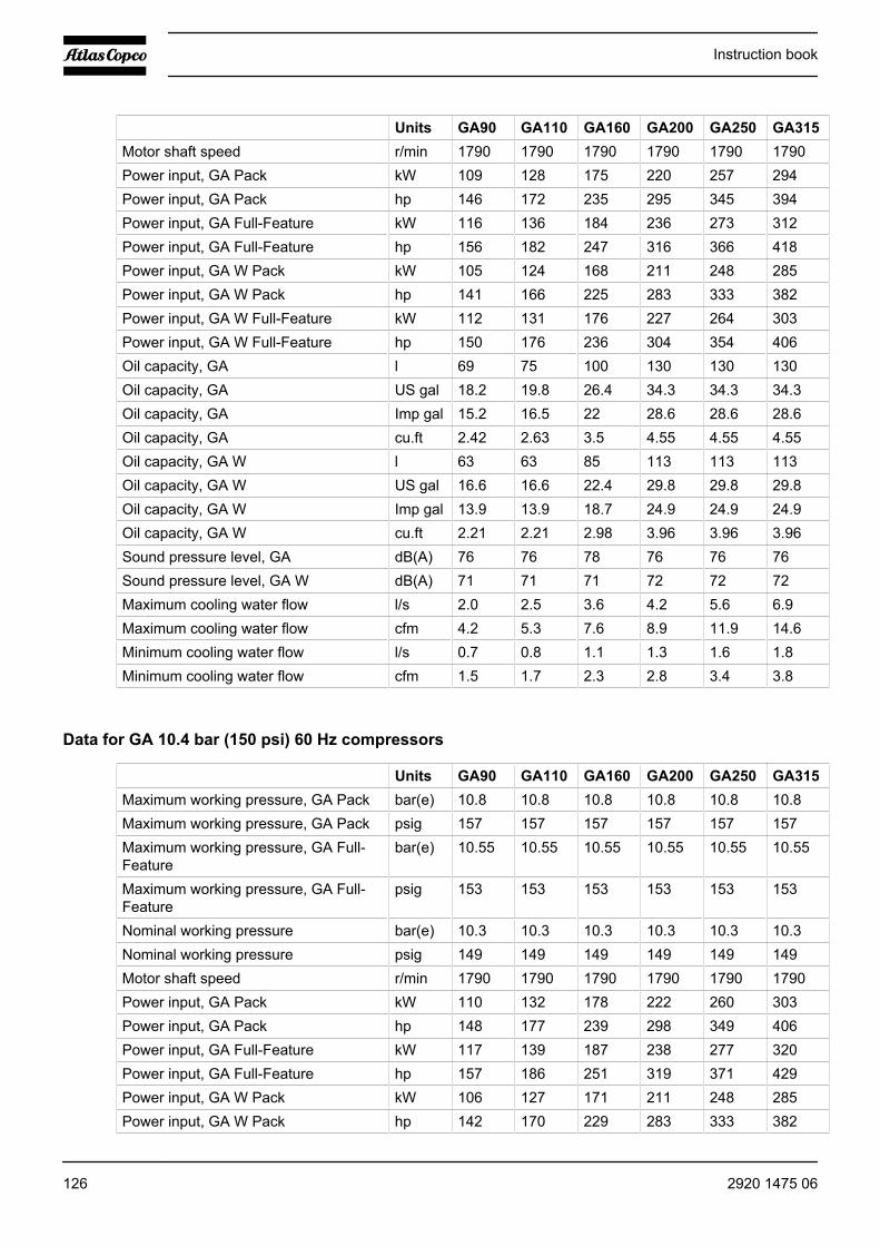
Units GA90 GA110 GA160 GA200 GA250 GA315Motor shaft speed r/min 1790 1790 1790 1790 1790 1790Power input, GA Pack kW 109 128 175 220 257 294Power input, GA Pack hp 146 172 235 295 345 394Power input, GA Full-Feature kW 116 136 184 236 273 312Power input, GA Full-Feature hp 156 182 247 316 366 418Power input, GA W Pack kW 105 124 168 211 248 285Power input, GA W Pack hp 141 166 225 283 333 382Power input, GA W Full-Feature kW 112 131 176 227 264 303Power input, GA W Full-Feature hp 150 176 236 304 354 406Oil capacity, GA l 69 75 100 130 130 130Oil capacity, GA US gal 18.2 19.8 26.4 34.3 34.3 34.3Oil capacity, GA Imp gal 15.2 16.5 22 28.6 28.6 28.6Oil capacity, GA cu.ft 2.42 2.63 3.5 4.55 4.55 4.55Oil capacity, GA W l 63 63 85 113 113 113Oil capacity, GA W US gal 16.6 16.6 22.4 29.8 29.8 29.8Oil capacity, GA W Imp gal 13.9 13.9 18.7 24.9 24.9 24.9Oil capacity, GA W cu.ft 2.21 2.21 2.98 3.96 3.96 3.96Sound pressure level, GA dB(A) 76 76 78 76 76 76Sound pressure level, GA W dB(A) 71 71 71 72 72 72Maximum cooling water flow l/s 2.0 2.5 3.6 4.2 5.6 6.9Maximum cooling water flow cfm 4.2 5.3 7.6 8.9 11.9 14.6Minimum cooling water flow l/s 0.7 0.8 1.1 1.3 1.6 1.8Minimum cooling water flow cfm 1.5 1.7 2.3 2.8 3.4 3.8
Data for GA 10.4 bar (150 psi) 60 Hz compressors
Units GA90 GA110 GA160 GA200 GA250 GA315Maximum working pressure, GA Pack bar(e) 10.8 10.8 10.8 10.8 10.8 10.8Maximum working pressure, GA Pack psig 157 157 157 157 157 157Maximum working pressure, GA Full-Feature
bar(e) 10.55 10.55 10.55 10.55 10.55 10.55
Maximum working pressure, GA Full-Feature
psig 153 153 153 153 153 153
Nominal working pressure bar(e) 10.3 10.3 10.3 10.3 10.3 10.3Nominal working pressure psig 149 149 149 149 149 149Motor shaft speed r/min 1790 1790 1790 1790 1790 1790Power input, GA Pack kW 110 132 178 222 260 303Power input, GA Pack hp 148 177 239 298 349 406Power input, GA Full-Feature kW 117 139 187 238 277 320Power input, GA Full-Feature hp 157 186 251 319 371 429Power input, GA W Pack kW 106 127 171 211 248 285Power input, GA W Pack hp 142 170 229 283 333 382
Instruction book
126 2920 1475 06

Units GA90 GA110 GA160 GA200 GA250 GA315Power input, GA W Full-Feature kW 113 133 179 227 264 303Power input, GA W Full-Feature hp 152 178 240 304 354 406Oil capacity, GA l 69 75 100 130 130 130Oil capacity, GA US gal 18.2 19.8 26.4 34.3 34.3 34.3Oil capacity, GA Imp gal 15.2 16.5 22 28.6 28.6 28.6Oil capacity, GA cu.ft 2.42 2.63 3.5 4.55 4.55 4.55Oil capacity, GA W l 63 63 85 113 113 113Oil capacity, GA W US gal 16.6 16.6 22.4 29.8 29.8 29.8Oil capacity, GA W Imp gal 13.9 13.9 18.7 24.9 24.9 24.9Oil capacity, GA W cu.ft 2.21 2.21 2.98 3.96 3.96 3.96Sound pressure level, GA dB(A) 76 76 78 76 76 76Sound pressure level, GA W dB(A) 71 71 71 72 72 72Maximum cooling water flow l/s 2.0 2.5 3.6 4.2 5.6 6.9Maximum cooling water flow cfm 4.2 5.3 7.6 8.9 11.9 14.6Minimum cooling water flow l/s 0.7 0.8 1.1 1.3 1.6 1.8Minimum cooling water flow cfm 1.5 1.7 2.3 2.8 3.4 3.8
Data for GA 13.8 bar (200 psi) 60 Hz compressors
Units GA90 GA110 GA160 GA250 GA315Maximum working pressure, GAPack
bar(e) 13.8 13.8 13.8 13.8 13.8
Maximum working pressure, GAPack
psig 200 200 200 200 200
Maximum working pressure, GAFull-Feature
bar(e) 13.55 13.55 13.55 13.55 13.55
Maximum working pressure, GAFull-Feature
psig 197 197 197 197 197
Nominal working pressure bar(e) 13.3 13.3 13.3 13.3 13.3Nominal working pressure psig 193 193 193 193 193Motor shaft speed r/min 1790 1790 1790 1790 1790Power input, GA Pack kW 111 134 178 269 307Power input, GA Pack hp 149 180 239 361 412Power input, GA Full-Feature kW 118 141 187 285 323Power input, GA Full-Feature hp 158 189 251 382 433Power input, GA W Pack kW 107 129 171 260 298Power input, GA W Pack hp 143 173 229 349 400Power input, GA W Full-Feature kW 113 136 179 276 314Power input, GA W Full-Feature hp 152 182 240 370 421Oil capacity, GA l 69 75 100 130 130Oil capacity, GA US gal 18.2 19.8 26.4 34.3 34.3Oil capacity, GA Imp gal 15.2 16.5 22 28.6 28.6
Instruction book
2920 1475 06 127
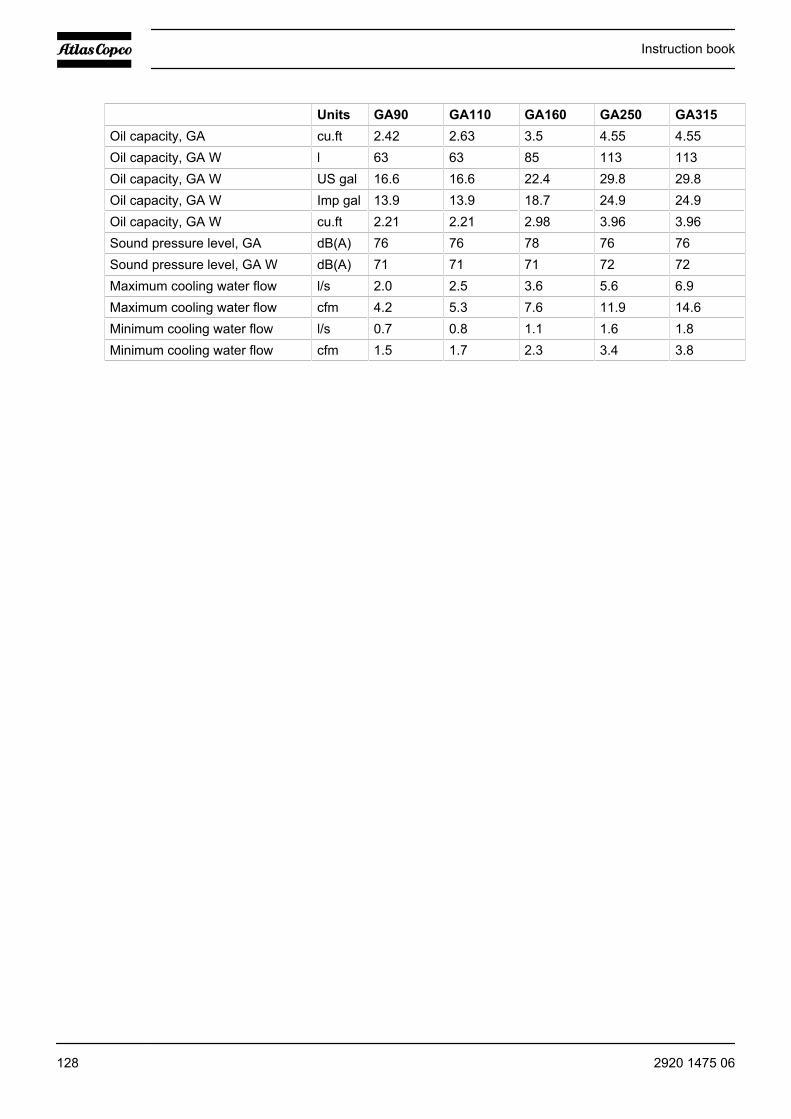
Units GA90 GA110 GA160 GA250 GA315Oil capacity, GA cu.ft 2.42 2.63 3.5 4.55 4.55Oil capacity, GA W l 63 63 85 113 113Oil capacity, GA W US gal 16.6 16.6 22.4 29.8 29.8Oil capacity, GA W Imp gal 13.9 13.9 18.7 24.9 24.9Oil capacity, GA W cu.ft 2.21 2.21 2.98 3.96 3.96Sound pressure level, GA dB(A) 76 76 78 76 76Sound pressure level, GA W dB(A) 71 71 71 72 72Maximum cooling water flow l/s 2.0 2.5 3.6 5.6 6.9Maximum cooling water flow cfm 4.2 5.3 7.6 11.9 14.6Minimum cooling water flow l/s 0.7 0.8 1.1 1.6 1.8Minimum cooling water flow cfm 1.5 1.7 2.3 3.4 3.8
Instruction book
128 2920 1475 06
10 Pressure equipment directives
PED instructions GA90 up to GA160
Product : GA90-160
This machine is a pressure assembly of cat. III according to 97/23/EC.
Parts of article 3.3 of 97/23/EC are subject to good engineering practice.
Parts of category I according to 97/23/EC are integrated into the machine and fall under the exclusion of articleI, section 3.6.
Parts subject to the Simple Pressure Vessel Directive 87/404/EEC are excluded from 97/23/EC according toarticle I, section 3.3.
The following pressure bearing parts are of category higher than I :
Oil separator vessel : Cat III
For GA 90 and GA 110: design pressure 15 bar(e), content 147 l
For GA 132 and GA 160: design pressure 15 bar(e), content 189 l
Design standard : ASME section VIII div. 1.
Safety valve : Cat IV
Design code : AD-Merkblätter, A2
PED instructions GA200 up to GA500
Product : GA 200-500
This machine is a pressure assembly of cat. IV according to 97/23/EC.
Parts of article 3.3 of 97/23/EC are subject to good engineering practice.
Parts of category I according to 97/23/EC are integrated into the machine and fall under the exclusion of articleI, section 3.6.
Parts subject to the Simple Pressure Vessel Directive 87/404/EEC are excluded from 97/23/EC according toarticle I, section 3.3.
The following pressure bearing parts are of category higher than I :
Oil separator vessel : Cat IV
For GA 200, GA 250 and GA315 60Hz, 1 vessel: design pressure 15 bar(e), content 305 l
Design standard : ASME section VIII div. 1.
Safety valve : Cat IV
Design code : AD-Merkblätter, A2
Instruction book
2920 1475 06 129
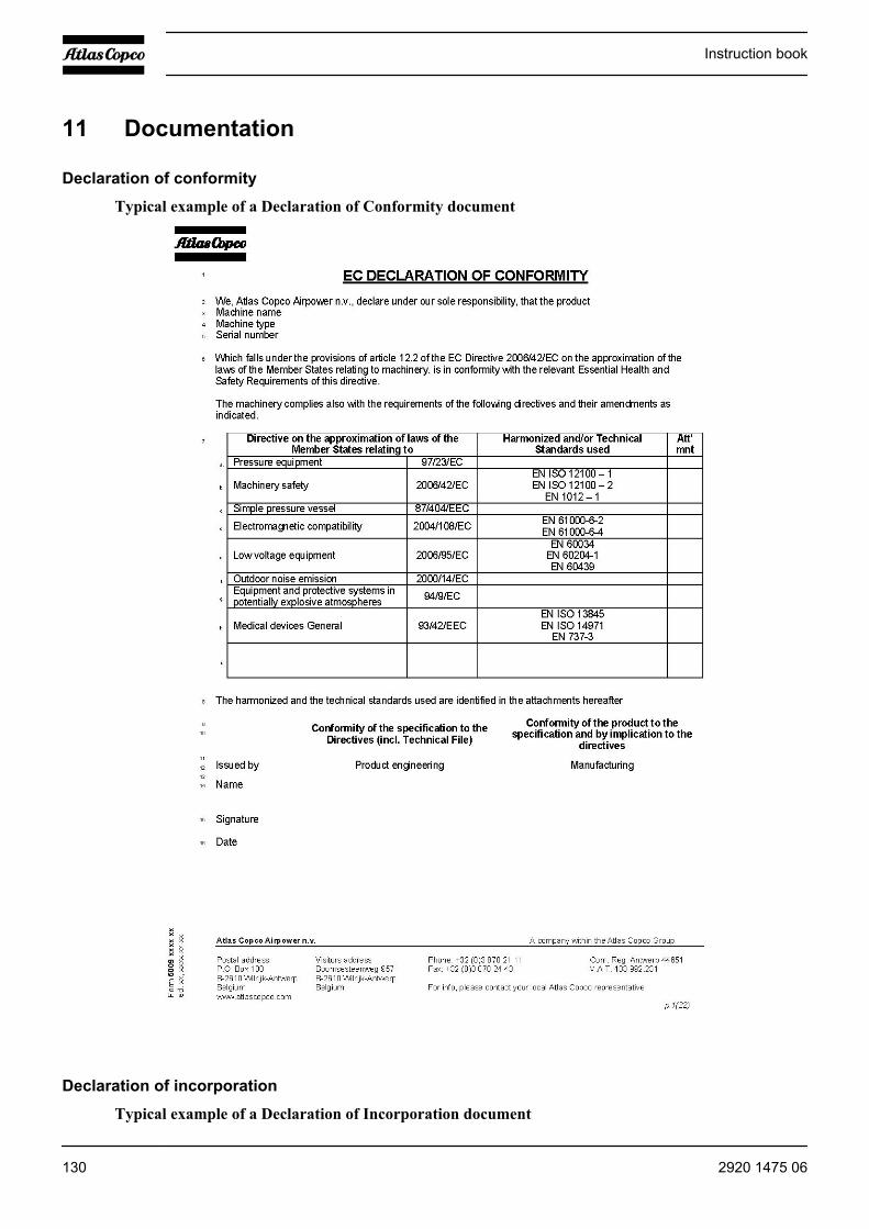
11 Documentation
Declaration of conformity
Typical example of a Declaration of Conformity document
Declaration of incorporation
Typical example of a Declaration of Incorporation document
Instruction book
130 2920 1475 06
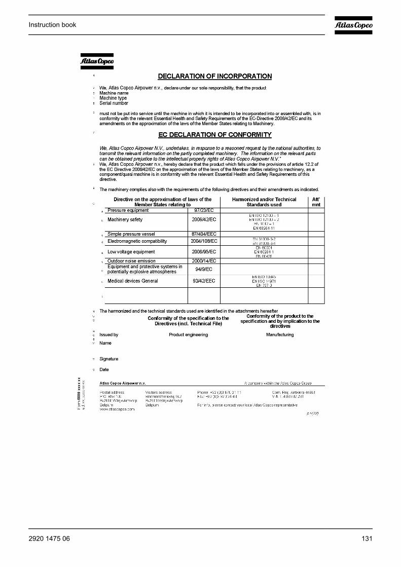
Instruction book
2920 1475 06 131


No.
292
0 14
75 0
6 / 2
010
- 03
What sets Atlas Copco apart as a company is our conviction thatwe can only excel in what we do if we provide the best possibleknow-how and technology to really help our customers produce,grow and succeed.
There is a unique way of achieving that - we simply call it the AtlasCopco way. It builds on interaction, on long-term relationshipsand involvement in the customers’ process, needs and objectives.It means having the flexibility to adapt to the diverse demands ofthe people we cater for.
It’s the commitment to our customers’ business that drives oureffort towards increasing their productivity through bettersolutions. It starts with fully supporting existing products andcontinuously doing things better, but it goes much further, creatingadvances in technology through innovation. Not for the sake oftechnology, but for the sake of our customer’s bottom line andpeace-of-mind.
That is how Atlas Copco will strive to remain the first choice, tosucceed in attracting new business and to maintain our positionas the industry leader.


![Atlas Copco (India) Limited · 3. Atlas Copco International B.V. ACO0101339 4. Atlas Copco AB ACO0101595, ACO0101097, A 0005191 and 10177354 5. Atlas Copco [I] Ltd Charitable Foundation](https://static.documents.pub/doc/80x56/5ec4197bfe534e04f779e397/atlas-copco-india-limited-3-atlas-copco-international-bv-aco0101339-4-atlas.jpg)


