Page 1
CNS SG/21
Appendix D to the Report
INTERNATIONAL CIVIL AVIATION ORGANIZATION
ASIA AND PACIFIC OFFICE
ATS Inter-Facility Data Communication (AIDC)
IMPLEMENTATION AND OPERATIONS GUIDANCE DOCUMENT
Edition 1.0 - July 2017
Page 2
AIDC Implementation and Operations Guidance Document
Edition 1.0 July 2017 2
Table of Contents
Chapter 1: INTRODUCTION ................................................................................................................... 4
1.1 Introduction ........................................................................................................................................ 4
1.2 The Arrangement of AIDC IGD ........................................................................................................ 4
1.3 Document History and Management ................................................................................................. 5
Chapter 2: ABBREVIATIONS.................................................................................................................. 6
2.1 Introduction: ....................................................................................................................................... 6
Chapter 3: REFERENCE DOCUMENTS ............................................................................................... 8
Chapter 4: AIDC MESSAGES .................................................................................................................. 9
4.1 Introduction ........................................................................................................................................ 9
4.2 Message Field Requirements ............................................................................................................. 9
4.3 AIDC Message Groups .................................................................................................................... 20
4.4 Core AIDC Messages ....................................................................................................................... 21
4.5 Application Management Messages ................................................................................................ 22
Chapter 5: AIDC IMPLEMENTATION CONSIDERATIONS .......................................................... 24
5.1 Introduction ...................................................................................................................................... 24
5.2 Pre-implementation Checklist .......................................................................................................... 24
5.3 Human Machine Interfaces .............................................................................................................. 25
5.4 Handling Implementation Issues ...................................................................................................... 26
5.5 HMI Considerations ......................................................................................................................... 28
Chapter 6: HARMONIZATION FRAMEWORK FOR AIDC IMPLEMENTATION ..................... 30
6.1 Introduction ...................................................................................................................................... 30
6.2 Harmonization Framework .............................................................................................................. 30
6.3 Template of Harmonization Framework for AIDC Implementation ............................................... 32
Chapter 7: AIDC PERFORMANCE MONITORING AND VALIDATION ..................................... 34
7.1 Introduction ...................................................................................................................................... 34
7.2 AIDC Performance Criteria ............................................................................................................. 34
7.3 AIDC Performance Monitoring ....................................................................................................... 37
7.4 AIDC Validation .............................................................................................................................. 38
Chapter 8: AIDC TRAINING ................................................................................................................. 40
8.1 Introduction ...................................................................................................................................... 40
Page 3
AIDC Implementation and Operations Guidance Document
Edition 1.0 July 2017 3
8.2 Training Objectives .......................................................................................................................... 40
8.3 Training Principles and Techniques ................................................................................................. 40
8.4 Training Procedure ........................................................................................................................... 41
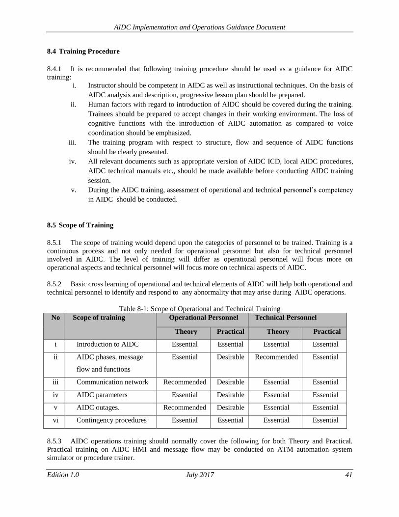
8.5 Scope of Training ............................................................................................................................. 41
Appendix A
Sample Letter of Agreement (LOA) /Memorandum of Understanding (MOU) ......................................... 44
Appendix B
Sample of AIDC Interoperability Tests ...................................................................................................... 48
List of Tables
Table 4-1: Contents of Field 14 .................................................................................................................. 10 Table 4-2: Field 14 Crossing Information examples .................................................................................. 12 Table 4-3: Field 14 Block Level examples ................................................................................................. 12 Table 4-4: Field 14 Mach Number examples ............................................................................................. 13 Table 4-5: Field 14 Mach Number removed example ............................................................................... 13 Table 4-6: Offset Weather Deviation example ........................................................................................... 14 Table 4-7: Offset Weather Deviation removed example ............................................................................ 15 Table 4-8: Contents of Field 15 .................................................................................................................. 16 Table 4-9: Field 15 examples ...................................................................................................................... 19 Table 4-10: AIDC Messages (PAN ICD AIDC Version 1.0) ..................................................................... 20 Table 4-11: Core AIDC Messages .............................................................................................................. 21 Table 4-12: Application Management Messages ........................................................................................ 22 Table 4-13: PAN ICD AIDC Version 1.0 Messages and their Field Composition .................................... 24 Table 5-1: Table of Common AIDC Issues ................................................................................................ 26 Table 6-1: Harmonization Framework for AIDC Implementation between ATSU1 and ATSU2 ............... 32 Table 7-1: Required Operational Response ................................................................................................ 35 Table 7-2: Performance Figures.................................................................................................................. 36 Table 8-1: Scope of Operational and Technical Training ........................................................................... 41
Page 4
AIDC Implementation and Operations Guidance Document
Edition 1.0 July 2017 4
Chapter 1: INTRODUCTION
1.1 Introduction
1.1.1 The ATS Inter-Facility Data-Communication (AIDC) Implementation and Operations Guidance
Document (IGD) is the result of the task entrusted to the Asia/Pacific ATS Inter-Facility Data-Link
Coordination Task Force (APA/TF) by APANPIRG. This main objective of this document is to provide
guidance, complementing relevant ICAO standards, on AIDC implementation within the APAC region.
The ultimate goal is that countries within APAC region are able to meet the regional AIDC targets
according to APAC seamless ATM plan and continue to advance on Flight and Flow Information for a
Collaborative Environment (FF-ICE) according to GANPs ASBU.
1.1.2 The Communications, Navigation, Surveillance and Air Traffic Management (CNS/ATM)
environment is an integrated system including physical systems (hardware, software, and communication
network), human elements (pilots, controllers and engineers), and the operational procedures for its
applications.
1.1.3 Recognized by ICAO under its Global Air Navigation Plan (GANP) and Aviation System Block
Upgrades (ASBU) framework as an effective tool to reduce manual intervention and ground-ground
coordination errors between adjacent ATSUs, the ATS Inter-facility Data Communications (AIDC) is a
data link application that provides the capability to exchange data between air traffic service units during
the notification, coordination and transfer of aircraft between flight information regions. It is an
automated system that facilitates routine coordination by providing a reliable and timely data exchange
between ATSUs in which accurate information can be derived directly from the system, thus effectively
reducing controllers’ workload and hence human errors.
1.2 The Arrangement of AIDC IGD
The AIDC IGD will define the following:
Chapter 1 Introduction
Chapter 2 Abbreviations
Chapter 3 Reference Documents
Chapter 4 AIDC Messages – Message sets to be used for AIDC Implementation
Chapter 5
AIDC Implementation Considerations – Information to support the implementation activities
including checklist and how to handle implementation issues.
Chapter 6
Harmonization Framework for AIDC Implementation – Information on the harmonization
framework on AIDC implementation activities and plan.
Chapter 7
AIDC Performance Monitoring and Validation – Information on the infrastructure supporting
the AIDC implementation including performance criteria, validation, monitoring, etc.
Chapter 8 AIDC Training – Guidance on operations and technical training to support effective
implementation
Page 5
AIDC Implementation and Operations Guidance Document
Edition 1.0 July 2017 5
1.3 Document History and Management
This document is managed by the APANPIRG. It was introduced as draft to the First meeting of the ATS
Inter-facility Data Communication Task Force Working Group on AIDC Implementation Guidance
Document (APA IGD WG/1) in Bangkok in December 2016, at which it was agreed to develop the draft
to an approved working document that provides guidance for States in the APAC region for effective
implementation of AIDC . The first edition was presented to APANPIRG for adoption in September
2017. It is intended to supplement SARPs, PANS and relevant provisions contained in ICAO
documentation and it will be regularly updated to reflect evolving provisions.
Page 6
AIDC Implementation and Operations Guidance Document
Edition 1.0 July 2017 6
Chapter 2: ABBREVIATIONS
2.1 Introduction:
When the following abbreviations are used in the present document they have the following meanings.
Where the abbreviation has “(ICAO)” annotated, the term has already been decoded in ICAO DOC 8400
(PANS-ICAO Abbreviations and Codes, Eighth Edition-2010).
Abbreviations
ABI Advance Boundary Information (AIDC Message)
ACC Area Control Centre
ACI Area of Common Interest
ACP Acceptance (AIDC Message)
AFTN Aeronautical Fixed Telecommunication Network
AIDC ATS Inter-Facility Data Communication
AMSS Automatic Message Switching System
ANSP Air Navigation Service Providers
AOC Acceptance of Control (AIDC Message)
APAC Asia and Pacific Office
APANPIRG Asia/Pacific Air Navigation Planning and Implementation Regional Group
ASBU Aviation System Block Upgrades
ASM Application Status Monitor (AIDC Message)
ATM Air Traffic Management
ATS Air Traffic Service
ATSU Air Traffic Service Unit
CDN Coordination Negotiation (AIDC Message)
COP Change Over Point
CPL Current Flight Plan (AIDC Message)
CRC Cyclic Redundancy Check
CRV Common aeRonautical Virtual private network
CWP Air Traffic Controller Work Position
DBM Data Base Management
EMG Emergency (AIDC Message)
EST Coordination Estimate (AIDC Message)
Page 7
AIDC Implementation and Operations Guidance Document
Edition 1.0 July 2017 7
FDPS Flight Plan Data Processing System
FF-ICE Flight and Flow Information for a Collaborative Environment
FPL Flight Plan
GANP Global Air Navigation Plan
GPS Global Positioning System
HMI Human Machine Interface
ICAO International Civil Aviation Organization
ICD Interface Control Document
IGD Implementation and Operations Guidance Document
LAM Logical Acknowledgement Message (AIDC Message)
LHD Large Height Deviation
LOA Letter of Agreement
LRM Logical Rejection Message (AIDC Message)
LTO Logical Time Out Response
MAC Cancellation of Notification and/or Coordination (AIDC Message)
MDT Mean Down Time for the System
MTBF Mean Time Between Failure
OEM Original Equipment Manufacturer
ORCAM Originating Region Code Allocation Method
PAC Preliminary Activate (AIDC Message)
PANS-ATM Procedures for Air Navigation Services – Air Traffic Management
PCA Profile Confirmation Acceptance (AIDC Message)
PCM Profile Confirmation Message (AIDC Message)
REJ Rejection (AIDC Message)
SOP Standard Operating Procedures
TF Task Force
TOC Transfer of Control (AIDC Message)
TRU Track Update (AIDC Message)
UTC Coordinated Universal Time
VVIP Very Very Important Person
Page 8
AIDC Implementation and Operations Guidance Document
Edition 1.0 July 2017 8
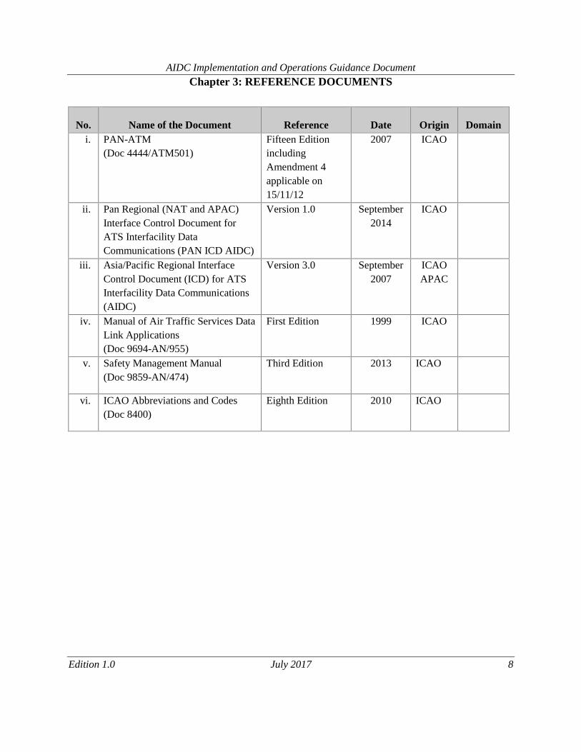
Chapter 3: REFERENCE DOCUMENTS
No. Name of the Document Reference Date Origin Domain
i. PAN-ATM
(Doc 4444/ATM501)
Fifteen Edition
including
Amendment 4
applicable on
15/11/12
2007 ICAO
ii. Pan Regional (NAT and APAC)
Interface Control Document for
ATS Interfacility Data
Communications (PAN ICD AIDC)
Version 1.0 September
2014
ICAO
iii. Asia/Pacific Regional Interface
Control Document (ICD) for ATS
Interfacility Data Communications
(AIDC)
Version 3.0 September
2007
ICAO
APAC
iv. Manual of Air Traffic Services Data
Link Applications
(Doc 9694-AN/955)
First Edition 1999 ICAO
v. Safety Management Manual
(Doc 9859-AN/474)
Third Edition 2013 ICAO
vi. ICAO Abbreviations and Codes
(Doc 8400)
Eighth Edition 2010 ICAO
Page 9
AIDC Implementation and Operations Guidance Document
Edition 1.0 July 2017 9
Chapter 4: AIDC MESSAGES
4.1 Introduction
4.1.1 This chapter describes the permitted fields and formats of AIDC messages. AIDC message fields
conform to ICAO definitions contained in PANS-ATM Appendix 3 except as described below for ICAO
flight plans Fields 14 and 15, as well as a “Text” field that is used in some AIDC messages.
4.1.2 ATS data in AIDC messages is enclosed between parentheses. Only one ATS message is
permitted to be included in each transmission.
4.1.3 Unless specified otherwise by the ATSU, the optional elements in the AIDC message fields
defined in the relevant AIDC ICD versions should be made available in the system by the manufacturer
and be user configurable. An example of the elements available is shown in Table 4-13 (PAN ICD AIDC
Version 1.0).
4.2 Message Field Requirements
Fields in AIDC messages do not always require the full contents of the defined ICAO message field.
This section specifies the usage of specific elements from message fields defined in the PANS-ATM as
well as additional information that may be included in Fields 14 and 15.
4.2.1 Field 3 requirements.
4.2.1.1 All AIDC messages should use Field 3a (Message type) only.
4.2.1.2 Fields 3b (Message number) and 3c (Message reference data) are not used, since in AIDC
messages the reference numbers contained in these fields are included in the Optional Data Field (ODF),
option 2 and 3. See PAN ICD AIDC Version 1.0, Chapter 3, Para 3.2.3.2.
4.2.2 Field 7 requirements.
4.2.2.1 Where Field 7 is required in an AIDC message, Field 7a (Aircraft Identification) must be
included. Fields 7b (SSR Mode) and 7c (SSR Code) are optional but should be included if the
information is available and applicable.
4.2.3 Field 13 requirements.
4.2.3.1 Where Field 13 is required in an AIDC message only Field 13a (Departure aerodrome), is
required. Field 13b (Departure time) is not to be transmitted. The use of ZZZZ in Field 13 is supported.
4.2.4 Field 14 requirements
Page 10
AIDC Implementation and Operations Guidance Document
Edition 1.0 July 2017 10
4.2.4.1 The following section describes the allowed contents of Field 14 (Estimate data), as well as
providing examples of how Field 14 data can be incorporated in an AIDC message.
4.2.4.2 Field 14 may contain a number of mandatory and optional items. The following Table 4-1
provides an overview on the type of information that may be included in Field 14.
Table 4-1: Contents of Field 14
Data
Example
Mandatory/Optional
Comment
Position
(14a)
0034S10413E
0017S10452E
ANITO
M
Normally a waypoint or system
calculated position on or near the FIR
or ACI boundary as agreed to through
bilateral agreement.
Field 14a is followed by an oblique
stroke “/”
Estimated time
(14b)
2200
M
The estimate for the position in 14a
Level
(14c)
A090
F330
F330F370
M
The coordinated level of the aircraft
While 14c is mandatory, the support
for the block level format is Optional
Supplementary
crossing data
(14d)
A120
F350
Included when
applicable
Use in conjunction with 14e to
indicate that an aircraft may be on
climb or descent at, or within
tolerances of, the FIR boundary
Page 11
AIDC Implementation and Operations Guidance Document
Edition 1.0 July 2017 11
Crossing
condition
(14e)
Example (A)
Example (B)
Example (C)
Included when
applicable
(A) The aircraft may be on climb
from the level specified in 14d
(B) The aircraft may be on descent
from the level specified in 14d
(C) The aircraft is cruise climbing
from the level specified in 14d.
The support for the cruise climb
format is optional
Mach Number
GM084
EM076
LM083
O
Used when a Mach Number speed
restriction has been assigned to the
aircraft by ATC.
Offset and
weather
deviation
W25R
W100E
O30L
O
When an offset or weather
deviation is in effect, the position
in14a should be a position on the
flight planned route, rather than the
offset route
Note1. Each item of optional information in Field 14 is separated from the previous item by an
oblique stroke “/”;
Note2. The order that the item is included in Field 14 is the order in which it is listed in Table 4-
1. For example, if an AIDC message were to include an assigned Mach cc as well as a weather
deviation, the Mach number information would precede the weather deviation information in
Field 14.
4.2.4.3 Supplementary Crossing Data and Crossing Conditions in Field 14
4.2.4.3.1 Field 14 may contain information that an aircraft is on climb, descent or cruise climb to
the specified level. This is achieved by including supplementary crossing data and crossing conditions in
Field 14.
4.2.4.3.2 The inclusion of cruise climb information in AIDC messages should only be made
following bilateral agreement.
Page 12
AIDC Implementation and Operations Guidance Document
Edition 1.0 July 2017 12
Table 4-2: Field 14 Crossing Information examples
Field 14
Explanation
ANITO/2130F310F290A
The aircraft is estimating ANITO at 2130, assigned F310
and is climbing from (or “above”) F290.
0034S10413E/0215F310F330B
The aircraft is estimating 30N160W at 0215, assigned
F310 and is descending from (or “below”) F330.
PARDI/1547F360F340C
The aircraft is estimating PARDI at 1547 and is cruise
climbing from F340 to F360.
4.2.4.4 Block level information in Field 14
4.2.4.4.1 Field 14 may contain information that an aircraft is operating in a block level clearance. It
is permissible to include supplementary crossing data and a crossing condition with a block level, but if
this occurs the supplementary information may only be a single level (i.e. it cannot be a block level).
Table 4-3: Field 14 Block Level examples
Field 14
Explanation
DUDIS/2125F320F340
The aircraft is estimating DUDIS at 2125, and is
operating in a block of levels between F320 and F340
(inclusive).
0700N10533E/0244F310F350F290A
The aircraft is estimating 0700N10533E at 0244, and has
been assigned a block of levels between F310 and F350
(inclusive) and is climbing to the cleared block and will be
at or above F290 at 0700N10533E.
4.2.4.4.2 The AIDC format does not support a cruise climb into a block clearance.
4.2.4.4.3 The inclusion of block level information in AIDC messages should only be made
following bilateral agreement.
4.2.4.5 Mach Number information in Field 14
4.2.4.5.1 Field 14 may contain information that an aircraft has been assigned a speed restriction
(Mach number). When included in an AIDC message, any Mach number information should always
follow directly after the level information and be separated from the level information by an oblique
stroke “/”.
Page 13
AIDC Implementation and Operations Guidance Document
Edition 1.0 July 2017 13
Table 4-4: Field 14 Mach Number examples
Field 14
Explanation
AKMON/0349F350/GM085 The aircraft is estimating AKMON at 0349 at F350 and
has been instructed to maintain M0.85 or greater
0145N10354E/0215F310/EM076 The aircraft is estimating 0145N10354E at 0215 at F310 and
has been instructed to maintain M0.76
4.2.4.5.2 The absence of speed information in Field 14 of an AIDC message provides advice that
any previously notified speed has been cancelled.
Table 4-5: Field 14 Mach Number removed example
Field 14
Explanation
ESPOB/1237F310F330B/LM083
The aircraft is estimating ESPOB at 1237, assigned F310 and
will cross ESPOB at or below F330, maintaining M0.83 or
less.
Subsequently followed by:
ESPOB/1238F310
The aircraft is now estimating ESPOB at 1238, is maintaining
F310 (i.e. no longer on descent at ESPOB), and the Mach
Number restriction has been cancelled.
4.2.4.5.3 The inclusion of Mach number information in AIDC messages should only be made
following bilateral agreement.
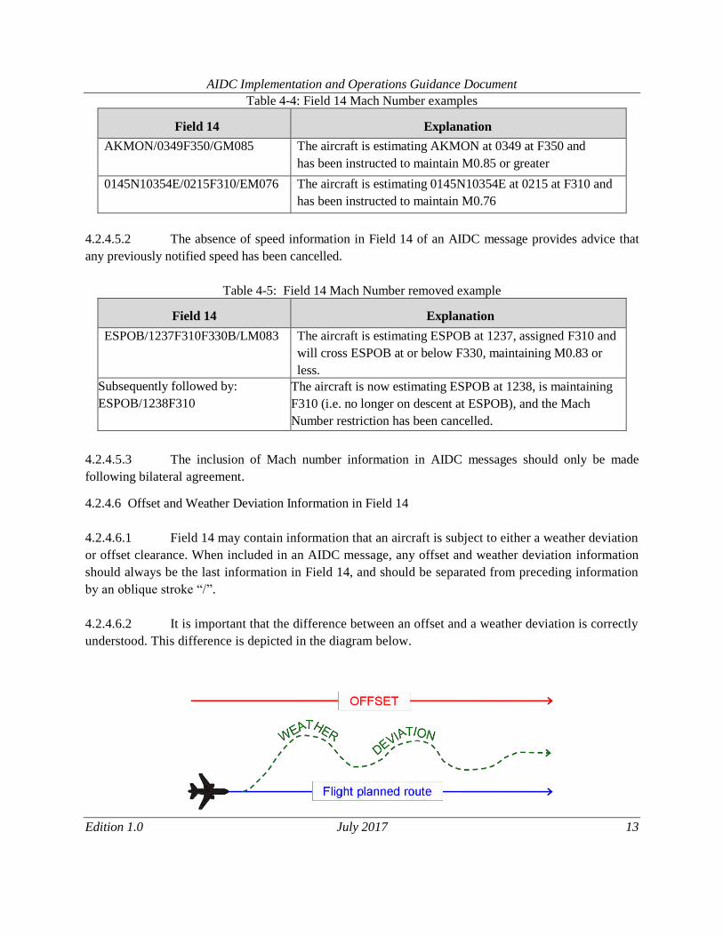
4.2.4.6 Offset and Weather Deviation Information in Field 14
4.2.4.6.1 Field 14 may contain information that an aircraft is subject to either a weather deviation
or offset clearance. When included in an AIDC message, any offset and weather deviation information
should always be the last information in Field 14, and should be separated from preceding information
by an oblique stroke “/”.
4.2.4.6.2 It is important that the difference between an offset and a weather deviation is correctly
understood. This difference is depicted in the diagram below.
Page 14
AIDC Implementation and Operations Guidance Document
Edition 1.0 July 2017 14
4.2.4.6.3 An offset is a flight trajectory that is parallel to the original route, offset by a specified
distance and direction. Once an aircraft is established on the offset, separation may be applied solely
based on the offset path.
4.2.4.6.4 A weather deviation permits an aircraft to operate anywhere between the original route
and the specified distance and direction from the original route. Separation must therefore be applied to
the entire airspace in which the aircraft has been cleared to operate in.
4.2.4.6.5 The following examples show various combinations of weather deviations and offsets,
combined with other optional information allowed in Field 14.
Table 4-6: Offset Weather Deviation example
Field 14
Explanation
0856N11551E/0140F330/W20L
The aircraft is estimating 0856N11551E at 0140,
maintaining F330, and has been cleared to deviate up to
20NM to the left of route.
TEGID/2330F310/GM084/O30R
The aircraft is estimating TEGID at 2330, maintaining
F310, instructed to maintain M0.84 or greater, and has
been cleared to offset 30NM to the right of route.
0949N11448E/0215F310F330/W25E The aircraft is estimating 0949N11448E at 0215, is
operating in a block of levels between F310 and F330
(inclusive), and has been cleared to deviate up to 25NM
either side of route.
LAXOR/0215F310F350F370B/W100L
The aircraft is estimating LAXOR at 0215, and has been
assigned a block of levels between F310 and F350
(inclusive), will cross LAXOR at or below F370, and has
been cleared to deviate up to 100NM to the left of route.
4.2.4.6.6 The absence of offset or weather deviation in Field 14 of an AIDC message provides
advice that any previously notified off-track information has been cancelled.
Page 15
AIDC Implementation and Operations Guidance Document
Edition 1.0 July 2017 15
Table 4-7: Offset Weather Deviation removed example
Field 14
Explanation
0042N10216E/1519F330/W15R
Subsequently followed by:
0042N10216E /1520F330
The aircraft is deviating up to 15NM right of track.
The aircraft is back on track (and one minute later than
previously coordinated).
4.2.4.6.7 When an aircraft is offsetting or deviating, the coordination point included in Field 14a
should be a position based on the flight planned route rather than the offset route. The estimate included in
Field 14b shall be the estimate for the “abeam” position for the position included in Field 14a.
4.2.4.6.8 The inclusion of offsets and weather deviation information in AIDC messages should
only be made following bilateral agreement. Depending on their operational requirements, some ATSUs
may choose to only implement the weather deviation format. If applicable, this should also be specified in
bilateral agreements.
4.2.5 Field 15 requirements
4.2.5.1 The following section describes the allowed contents of Field 15 (Route), as well as providing
examples of how Field 15 data can be incorporated in an AIDC message.
4.2.5.2 A number of different AIDC messages (e.g. ABI, PAC, CPL, CDN and PCM) may contain Field
15 (Route) information. Depending on the AIDC message being used, this route information may be either
the current cleared route of the aircraft, or a proposed amendment to it.
Page 16
AIDC Implementation and Operations Guidance Document
Edition 1.0 July 2017 16
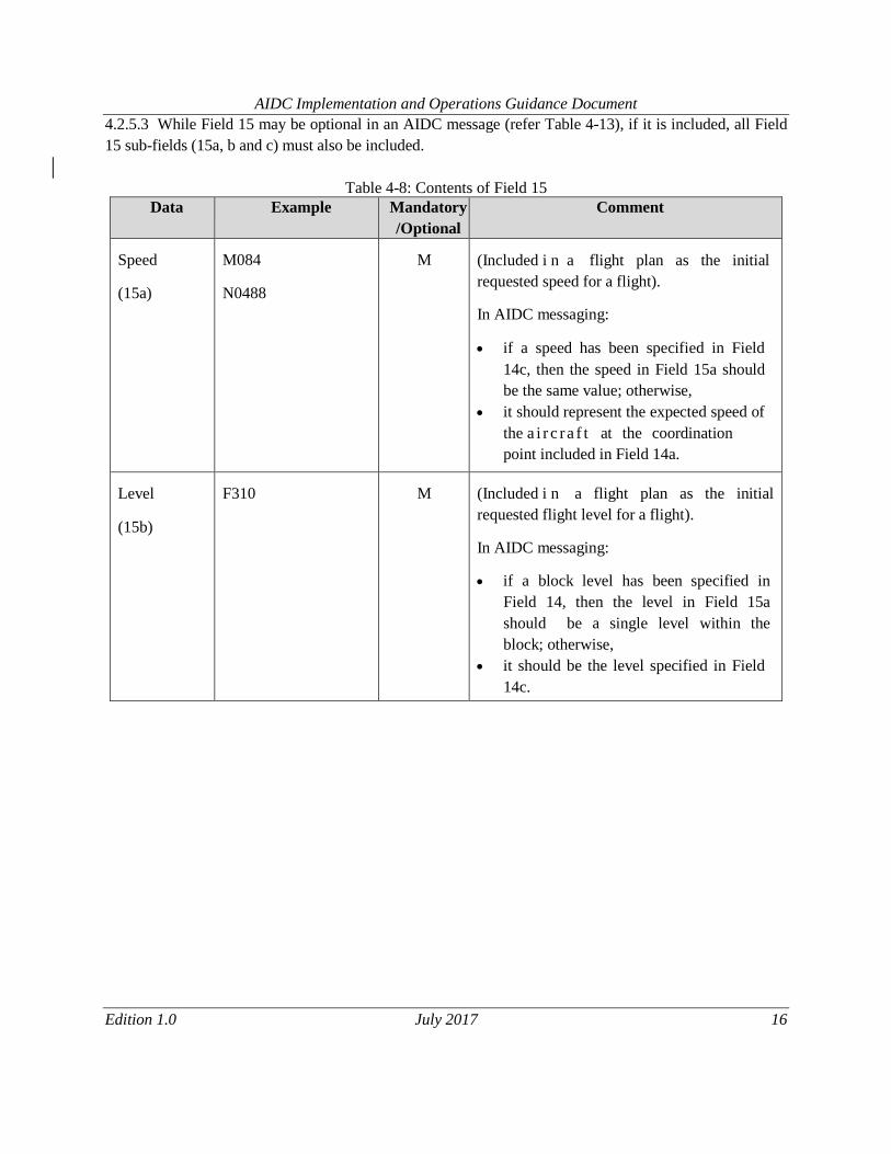
4.2.5.3 While Field 15 may be optional in an AIDC message (refer Table 4-13), if it is included, all Field
15 sub-fields (15a, b and c) must also be included.
Table 4-8: Contents of Field 15
Data Example Mandatory
/Optional
Comment
Speed
(15a)
M084
N0488
M
(Included i n a flight plan as the initial
requested speed for a flight).
In AIDC messaging:
if a speed has been specified in Field
14c, then the speed in Field 15a should
be the same value; otherwise,
it should represent the expected speed of
the a i r c r a f t at the coordination
point included in Field 14a.
Level
(15b)
F310
M
(Included i n a flight plan as the initial
requested flight level for a flight).
In AIDC messaging:
if a block level has been specified in
Field 14, then the level in Field 15a
should be a single level within the
block; otherwise,
it should be the level specified in Field
14c.
Page 17
AIDC Implementation and Operations Guidance Document
Edition 1.0 July 2017 17
Data Example Mandatory
/Optional
Comment
Route
(15c)
LAXOR
VMR
WSSS
094937N1144829E
033341N1065534E
L625, N884
SJ235100
M080F350
M084
F370
M084F370
1230
T
DCT
M The route (or proposed route) of flight. It may
contain any or all of the following elements:
Waypoint
Navigation aid
Aerodrome
Latitude/longitude
Latitude/longitude
ATS route
Place/bearing/distance
Speed/level changes (See Note 2)
Speed restriction
Level restriction
Speed/Level restriction (See Note 2)
Time associated with a restriction. May
include a suffix of “A”, “B” or “L”
Truncation indicator (‘T’)
Direct to
Note 1: The contents of Field 15c are defined in PANS-ATM Appendix 3, with the exception of
level/time/speed restrictions which are described in PAN ICD AIDC Version 1.0 under paragraph
2.4 Restriction Formats. Planned speed/level changes from the filed FPL are included in some
AIDC implementations although they do not reflect the current cleared profile of the aircraft.
Note 2: Flight planned speed/level changes and level/time/speed restrictions as defined in 2.4
Restriction Formats of PAN ICD AIDC Version 1.0, cannot both be included in Field 15
because in some cases they both use the same format. ATSUs should specify in bilateral
agreements which group of information (if any) will be supported.
4.2.5.4 At the minimum, Field 15 in an AIDC message should commence at a position prior to the ACI
associated with the adjacent FIR. Some ATSUs may include route information commencing at the
Departure aerodrome.
WSSS
TOMAN SABIP KAMIN DARMU SAKMA
WBSB
Page 18
AIDC Implementation and Operations Guidance Document
Edition 1.0 July 2017 18
4.2.5.5 Field 15 information transmitted by ATSU1 to ATSU2 should commence at (or before) SABIP.
This permits ATSU2 to calculate the profile of the aircraft commencing at the ACI boundary.
4.2.5.6 ATS Route
4.2.5.6.1 An ATS route may only be preceded and followed by a waypoint that is defined to be
on that ATS route.
4.2.5.7 Latitude/Longitudes
4.2.5.7.1 Latitude and longitude in Field 15 must either be both in whole degrees, or both in
degrees and minutes.
4.2.5.8 Flight Planned Speed/Level Changes
4.2.5.8.1 Some ATSUs may include flight planned speed/level changes in Field 15c although
they do not reflect the current cleared profile of the aircraft. An ATSU receiving Field 15c data
containing planned FPL level speed changes should accept the information. However, the receiving
ATSU may choose not to use the planned FPL level speed changes to update their flight plan, and may
choose not to forward it in any subsequent AIDC messages.
4.2.5.9 Time/Speed/Level Restrictions
4.2.5.9.1 While the information in Field 14 defines the conditions for crossing the ACI or FIR
boundary, ATSU1 may include in Field 15 time/speed/level restrictions that have been issued in a
clearance to an aircraft. These clearances may include a requirement for an aircraft to cross a position at a
specific time or to change level and/or speed at or by a specific time or position.
4.2.5.10 Truncation Indicator
4.2.5.10.1 While it is desirable for Field 15 to describe the entire route to destination, on occasions
this may not be possible. If it is not possible to define the route to destination, it is necessary to truncate
(delete the remainder of the route) and insert a truncation indicator (‘T’).
4.2.5.10.2 Bilateral agreements should define the use and meaning of the truncation indicator. For
example the truncation indicator may represent:
i. the point at which the route in Field 15 rejoins the original flight planned route, or
ii. the end of the oceanic cleared route.
4.2.5.10.3 The truncation indicator should only follow a significant point in Field 15 and should
not follow an ATS Route, or “DCT”.
Note: A significant point also refers to a significant point followed or preceded by:
i. A speed/level change; or
ii. A speed and/or level and/or time restriction
Page 19
AIDC Implementation and Operations Guidance Document
Edition 1.0 July 2017 19
Table 4-9: Field 15 examples
SY L521 AA
Navaid, ATS Route
Note that both “SY” and “AA” are defined on
airway L521
SY L521 GEROS 3425S16300E LUNBI AA
Navaid, ATS Route, waypoint, lat/long
(ddmm)
SY GEROS GEROS045100 ESKEL L521 AA
Place/bearing/distance
SY L521 GEROS/M085F370 L521 AA DCT BB
Speed/level change, DCT
SY L521 LUNBI T
SY L521 GEROS 3425S16300E T SY L521
LUNBI/M085F370 T
Truncation indicator
SY L521 GEROS/F370 L521 F370/LUNBI AA
SY GEROS/2245L ESKEL/M085F390 AA SY L521
M084F350/GEROS/1230A ESKEL/M083
L521 AA
Restrictions
4.2.6 Field 16 Requirements
4.2.6.1 Where Field 16 is required in an AIDC message, only Field 16a (Destination aerodrome), is
required. Field 16b (Total estimated elapsed time) and Field 16c (Alternate aerodrome/s) are not to be
transmitted. The use of ZZZZ in Field 16 is supported.
4.2.7 Field 18 Requirements
4.2.7.1 Field 18 should contain other information from the current flight plan and is used to update the
flight plan at the receiving ATSU.
4.2.7.2 When transmitting Field 18 in an AIDC message, all Field 18 indicators should be included, even
if the change only affects data in an individual Field 18 indicator. However, ATSUs may agree by
bilateral agreement to omit specific indicators (e.g. EET/) if required. If omitting indicators, ATSUs
should have due regard to the potential effect to downstream ATSUs.
4.2.7.3 The contents of Field 18 in AIDC messages should be specified in bilateral agreements between
ATSUs.
Note: Some legacy implementations allowed provision for the modification of individual sub
fields by communicating only that specific subfield. This is not recommended practice.
Page 20
AIDC Implementation and Operations Guidance Document
Edition 1.0 July 2017 20
4.2.7.4 In some AIDC messages, Field 18 may contain only a RMK/ indicator which is used to convey
free text data information. This applies to the MAC, EMG, LRM and MIS messages.
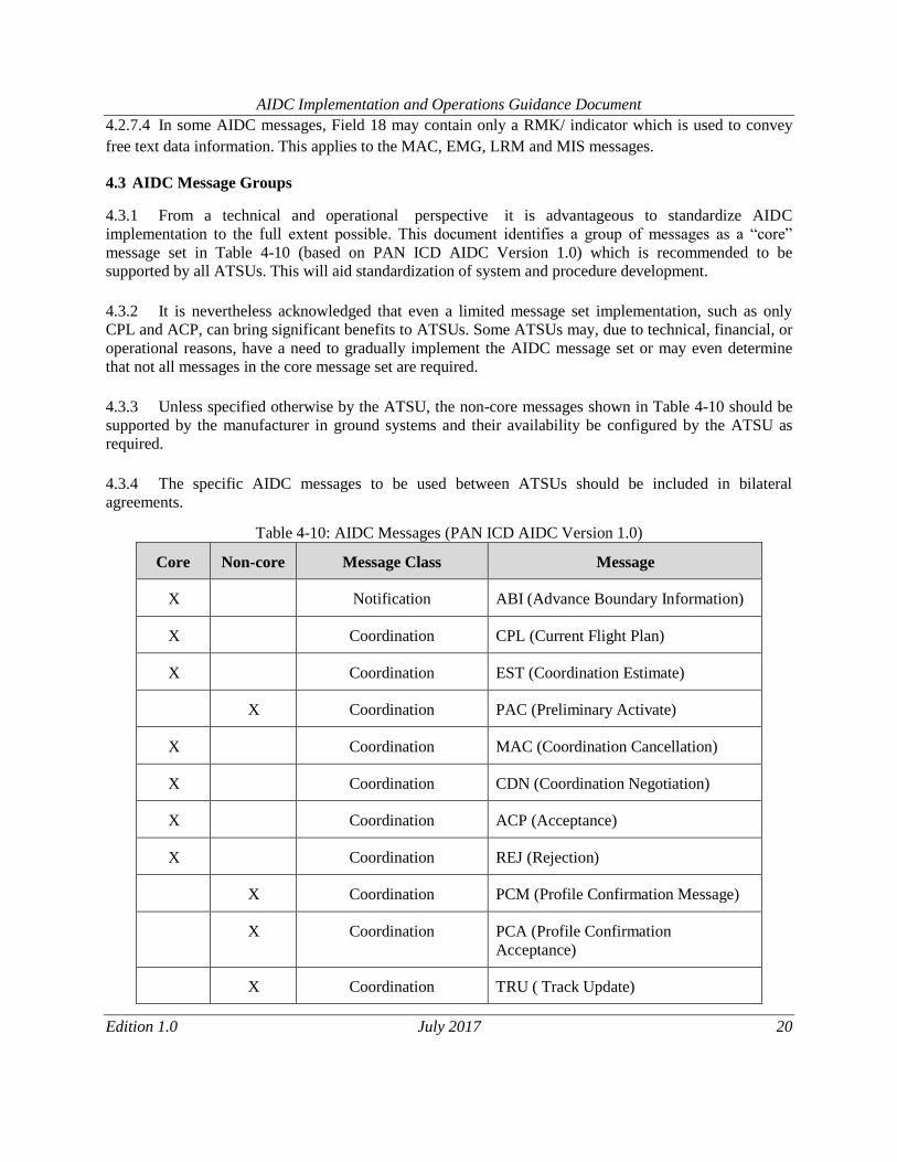
4.3 AIDC Message Groups
4.3.1 From a technical and operational perspective it is advantageous to standardize AIDC
implementation to the full extent possible. This document identifies a group of messages as a “core”
message set in Table 4-10 (based on PAN ICD AIDC Version 1.0) which is recommended to be
supported by all ATSUs. This will aid standardization of system and procedure development.
4.3.2 It is nevertheless acknowledged that even a limited message set implementation, such as only
CPL and ACP, can bring significant benefits to ATSUs. Some ATSUs may, due to technical, financial, or
operational reasons, have a need to gradually implement the AIDC message set or may even determine
that not all messages in the core message set are required.
4.3.3 Unless specified otherwise by the ATSU, the non-core messages shown in Table 4-10 should be
supported by the manufacturer in ground systems and their availability be configured by the ATSU as
required.
4.3.4 The specific AIDC messages to be used between ATSUs should be included in bilateral
agreements.
Table 4-10: AIDC Messages (PAN ICD AIDC Version 1.0)
Core
Non-core
Message Class
Message
X
Notification
ABI (Advance Boundary Information)
X
Coordination
CPL (Current Flight Plan)
X
Coordination
EST (Coordination Estimate)
X
Coordination
PAC (Preliminary Activate)
X
Coordination
MAC (Coordination Cancellation)
X
Coordination
CDN (Coordination Negotiation)
X
Coordination
ACP (Acceptance)
X
Coordination
REJ (Rejection)
X
Coordination
PCM (Profile Confirmation Message)
X
Coordination
PCA (Profile Confirmation
Acceptance)
X
Coordination
TRU ( Track Update)
Page 21
AIDC Implementation and Operations Guidance Document
Edition 1.0 July 2017 21
Core
Non-core
Message Class
Message
X
Transfer of Control
TOC (Transfer of Control)
X
Transfer of Control
AOC (Acceptance of Control)
X
General Information
EMG (Emergency)
X
General Information
MIS (Miscellaneous)
X
Application Management
LAM (Logical Acknowledgement
Message)
X
Application Management
LRM (Logical Rejection Message)
X
Application Management
ASM (Application Status Monitor)
X
Application Management
FAN ( FANS Application Message)
X
Application Management
FCN (FANS Completion Notification)
X
Surveillance Data Transfer
ADS (Surveillance ADS-C)
4.4 Core AIDC Messages
4.4.1 This section lists down the basic core AIDC messages for the initial implementation phase (ABI,
EST, ACP, AOC and TOC) that are recommended to be adopted. These messages are also identified are
part of the ASBU B0 recommendations pertaining to AIDC implementation
4.4.2 The complete list of AIDC messages, their purpose, message format and examples can be found
in the relevant “AIDC Messages” chapter of the various versions of AIDC ICD.
Table 4-11: Core AIDC Messages
AIDC
Message
Purpose Message format
ABI An ABI message is transmitted to provide
information on a flight to the receiving ATSU. The
purpose of the ABI is to synchronize the flight
plan information held between two ATS Units.
The transmission of the initial ABI will normally
be triggered at an agreed time or position prior to
the common boundary or ACI, or possibly by a
change in flight state. Before coordination occurs,
amendments to information contained in a
ICD documents can be referred
to for the required message
format and examples.
Page 22
AIDC Implementation and Operations Guidance Document
Edition 1.0 July 2017 22
AIDC
Message
Purpose Message format
previously transmitted ABI should be notified by
the transmission of another ABI.
EST An EST message is used to initiate coordination
for a flight.
The transmission of the EST message is used in
conjunction with (and generally following) an ABI
message and is triggered at an agreed time or
position prior to the common boundary or ACI, or
possibly by a change in flight state.
The only valid response to an EST message is an
ACP message, which closes the coordination
dialogue.
Respective ICD documents can
be referred to for the required
message format and examples.
ACP An ACP message is used to confirm that the
coordination proposed in a received CPL, CDN,
EST or PAC message is acceptable and to close the
coordination dialogue. The agreed coordination
conditions are updated in accordance with the
proposed coordination.
An ACP message is linked to the original AIDC
message using message identifier and reference
identifier information described in the PAN ICD
AIDC Version 1.0, section 3.2 Message Headers,
Timers and ATSU Indicators.
Respective ICD documents can
be referred to for the required
message format and examples.
TOC The TOC message is sent to propose executive
control of a flight to the receiving ATSU.
Respective ICD documents can
be referred to for the required
message format and examples.
AOC The AOC message is transmitted in response to a
received TOC message to indicate acceptance of
executive control of a flight.
Respective ICD documents can
be referred to for the required
message format and examples.
4.5 Application Management Messages
Table 4-12: Application Management Messages
AIDC
Message
Purpose Message format
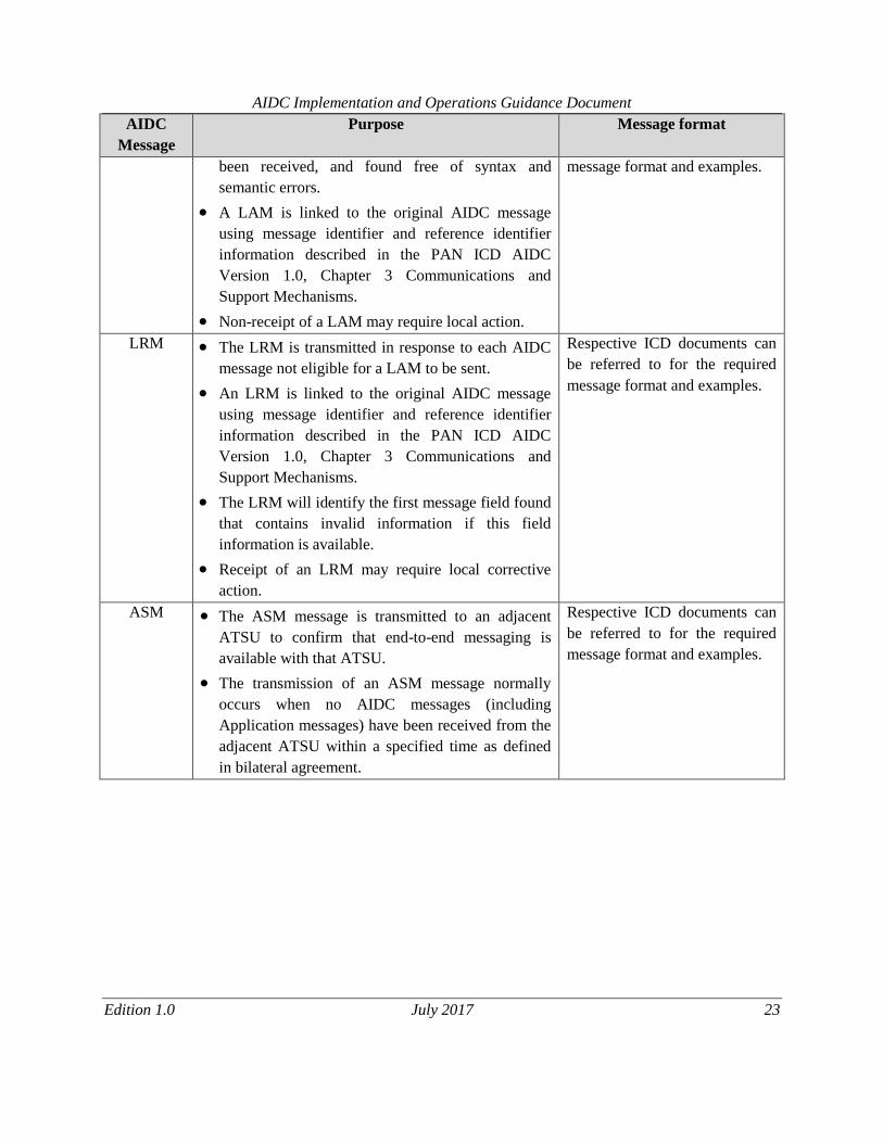
LAM The LAM is transmitted in response to each AIDC
message (except for another LAM or LRM) that has
Respective ICD documents can
be referred to for the required
Page 23
AIDC Implementation and Operations Guidance Document
Edition 1.0 July 2017 23
AIDC
Message
Purpose Message format
been received, and found free of syntax and
semantic errors.
A LAM is linked to the original AIDC message
using message identifier and reference identifier
information described in the PAN ICD AIDC
Version 1.0, Chapter 3 Communications and
Support Mechanisms.
Non-receipt of a LAM may require local action.
message format and examples.
LRM The LRM is transmitted in response to each AIDC
message not eligible for a LAM to be sent.
An LRM is linked to the original AIDC message
using message identifier and reference identifier
information described in the PAN ICD AIDC
Version 1.0, Chapter 3 Communications and
Support Mechanisms.
The LRM will identify the first message field found
that contains invalid information if this field
information is available.
Receipt of an LRM may require local corrective
action.
Respective ICD documents can
be referred to for the required
message format and examples.
ASM The ASM message is transmitted to an adjacent
ATSU to confirm that end-to-end messaging is
available with that ATSU.
The transmission of an ASM message normally
occurs when no AIDC messages (including
Application messages) have been received from the
adjacent ATSU within a specified time as defined
in bilateral agreement.
Respective ICD documents can
be referred to for the required
message format and examples.
Page 24
AIDC Implementation and Operations Guidance Document
Edition 1.0 July 2017 24
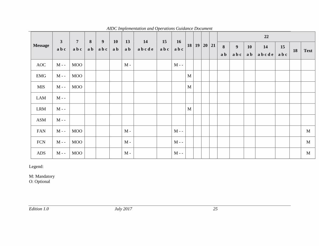
Table 4-13: PAN ICD AIDC Version 1.0 Messages and their Field Composition
Message
3
a b c
7
a b c
8
a b
9
a b c
10
a b
13
a b
14
a b c d e
15
a b c
16
a b c
18
19
20
21
22
8
a b
9
a b c
10
a b
14
a b c d e
15
a b c
18
Text
ABI
M - -
MOO
M -
MMMOO
M - -
OO
MMM
OO
MMM
O
CPL
M - -
MOO
MM
MM
M
MM
M -
MMMOO
MMM
M - -
M
EST
M - -
MOO
M -
MMMOO
M - -
PAC
M - -
MOO
M -
MMMOO
M - -
OO
OOO
OO
OOO
O
MAC
M - -
MOO
M -
M - -
OOOOO
O
CDN
M - -
MOO
M -
M - -
OO
OOOOO
OOO
O
O
ACP
M - -
MOO
M -
M - -
REJ
M - -
MOO
M -
M - -
PCM
M - -
MOO
M -
MMMOO
M - -
OO
OOO
OO
OOO
O
PCA
M - -
MOO
M -
M -
TRU
M - -
MOO
M -
M - -
M
TOC
M - -
MOO
M -
M - -
Page 25
AIDC Implementation and Operations Guidance Document
Edition 1.0 July 2017 25
Message
3
a b c
7
a b c
8
a b
9
a b c
10
a b
13
a b
14
a b c d e
15
a b c
16
a b c
18
19
20
21
22
8
a b
9
a b c
10
a b
14
a b c d e
15
a b c
18
Text
AOC
M - -
MOO
M -
M - -
EMG
M - -
MOO
M
MIS
M - -
MOO
M
LAM
M - -
LRM
M - -
M
ASM
M - -
FAN
M - -
MOO
M -
M - -
M
FCN
M - -
MOO
M -
M - -
M
ADS
M - -
MOO
M -
M - -
M
Legend:
M: Mandatory
O: Optional
Page 26
AIDC Implementation and Operations Guidance Document
Edition 1.0 July 2017 24
Chapter 5: AIDC IMPLEMENTATION CONSIDERATIONS
5.1 Introduction
5.1.1 The effectiveness of AIDC functionality depends on many factors, including ATM automation
systems, manufacturer of the equipment, Communication network, weather-related factors, operational
and technical training, Airspace design, Coordination procedures between different ATSU’s, etc. Some
problems/difficulties observed during implementation/testing of AIDC procedures are of common nature
irrespective of different OEM’s and different States. Such problems, their possible cause and their
solution evolved over time may be of great help to States in the process of implementing AIDC.
5.1.2 Every effort should be made to avoid common errors through sharing of experiences of ATSUs,
who have successfully implemented AIDC.
5.1.3 All States/Administrations have been requested to designate a focal point for AIDC
implementation. The updated list is available on ICAO APAC website. In case of any issues, support can
be requested through these focal points.
5.2 Pre-implementation Checklist
5.2.1 Prior to the implementation of AIDC, following may have to be considered by ATSUs. ATSUs
can choose to adopt these recommendations with their counterparts based on the local requirements.
No. Considerations Yes /
No Remarks, if any
i. AIDC Version N/A
Version of AIDC ICD
adopted by ATSU
ii. The communications network (e.g. AFTN, etc.) is able to support
AIDC operations effectively without overloading the existing
infrastructure.
iii. List of AIDC messages applicable between the two ATSUs (ABI,
EST, CPL, etc.) and parameters are agreed.
AIDC parameters to
be included in the
LOAs.
iv. AIDC parameters of ATM automation systems have been
configured for the AIDC connection (e.g. parameters for
Coordination messages, Enable/Disable AIDC etc.).
v. ATM automation systems and associated sub-systems are time
synchronized (GPS / UTC).
Page 27
AIDC Implementation and Operations Guidance Document
Edition 1.0 July 2017 25
No. Considerations Yes /
No Remarks, if any
vi. Comprehensive tests with AIDC use cases completed with pairing
ATSUs to ensure correct implementation and avoid unexpected
responses.
vii. Check and ensure that the Change Over Point (COP) is consistent
between the two ATSUs.
viii. Procedures to revert to Voice coordination have been defined by
ATSUs in cases where deviations from COP cannot be handled by
ATM automation systems.
ix. Contingency procedures have been published to cover AIDC
failures. This procedure shall also address any increase in
additional workload as a result of AIDC failure.
x. Operational and technical personnel are trained to handle AIDC.
xi. Communication network performance latency is monitored and
recorded.
xii. Standard Operating Procedures (SOPs) for AIDC operations are
published. Special cases where AIDC is not applicable have been
identified (e.g. VVIP movements).
xiii. A Safety Assessment for the implementation of AIDC is carried
out.
5.3 Human Machine Interfaces
5.3.1 ANSPs should clearly specify requirements regarding Human Machine Interface (HMI) for a new
ATM automation system or an upgrade. Generally, the following points may be considered:
i. User friendliness: choice of presentation in harmony with intended operators’ environment
(ATC centre), homogeneous and systematic presentation of interactions (similar actions
required for similar inputs and similar feedbacks given, in all sub-elements/windows of the
displays) ;
ii. Ergonomics: fatigue due to postural or musculoskeletal discomfort and eye focal length
discomfort should be minimized, and adequate colours, font size, symbols, contrasts and
brightness configured;
Page 28
AIDC Implementation and Operations Guidance Document
Edition 1.0 July 2017 26
iii. Efficiency: efficient dialogues and guidance for inputs provided by the system, timely and
appropriate feedback regarding operators’ inputs and errors, efficient and appropriate alert
and warning management avoiding unnecessary overload of the operator or the system (the
latter due to non-acknowledged alerts/warnings);
iv. Ease of Learning: consistency and homogeneity of operators’ actions through HMI.
5.3.2 With regard to AIDC, most interactions should be conducted through the label (air situation
display) or electronic flight strip. It should not be done via a dedicated message box or flight plan
presentation where actions to take/feedbacks/alerts could be overlooked and mis-association of the
messages for flights could occur. The AIDC coordination status should also be displayed in Electronic
Flight Progress Strips to increase situational awareness regarding the status of flight coordination. Any
need to revert to voice communications should be clearly indicated.
5.4 Handling Implementation Issues
5.4.1 Over a period of time during testing and implementation of AIDC across ICAO-APAC region,
several error messages and issues were encountered by different concerned ATSUs. Some of these issues
are of common nature and some of them may be unique for a particular ATSU. Such messages compiled
from various ATSUs are provided in Table 5-1 below, with a brief description of the errors, possible
causes and recommended actions. These AIDC issues are not exhaustive and listed as reference only.
Table 5-1: Table of Common AIDC Issues
No. Fault Category Fault Description Cause Recommended Actions
i. ATM
Automation
system
Rejection of AIDC
messages by
receiving system due
to Error message 61,
Cyclic Redundancy
Check (CRC) Error.
Error is likely because
sending ATM automation
system is generating extra
undesirable spaces
This error can be
overcome by making
changes in sender ATM
automation system so as
not to generate any extra
spaces while transmitting
AIDC messages.
ii. ATM
Automation/AFT
N system
Coordination
protocol dialogue
timeout
Likely non-synchronization
of time in the pairing ATM
automation/AFTN systems
Automatic time
synchronization through
GPS servers in ATM
automation/AFTN
systems at both receiving
and sending system is
required to be done for
smooth exchange of
AIDC messages.
iii. Communication
Network
a) Latency in
communication
network (AFTN
If due to network latency, no
automatic system response
is received by the sender
Expand the bandwidth of
existing AFTN link or
increase the message
Page 29
AIDC Implementation and Operations Guidance Document
Edition 1.0 July 2017 27
No. Fault Category Fault Description Cause Recommended Actions
link), resulting in
message time-out
errors b) Message timeout
errors due to
possible re-routing
of messages in case
of failure of direct
AFTN link.
system in a fixed time, then
the sender system generates
a LTO (time out response).
time-out parameter for
all messages to avoid
generation of time ou
response.
iv. Airspace Design/
Procedures
ABI messages of
some of the aircrafts
are not correlated
with Flight plan
available in ATM
automation system
Rejection of ABI messages
exchanged between system
due to route error and
mismatch in coordination
timing. ATM automation
system may reject the
incoming ABI message
because of unrecognised
route portion (depends on
how common airways are
defined in the pairing
systems - Some airways
may be defined up to a
certain extent in next FIR,
while others may be defined
only up to the FIR
boundary)
Modification in airways
(like imaginary points)
may be considered in the
database of both pairing
ATSUs ATM systems
for effective acceptance
of AIDC messages.
v. AIDC message
format
AIDC messages in
pre-2012 format
ATM system to be
modified to support
ICAO FPL 2012 format
vi. AIDC message
format Some ATM
automation systems
rejected
latitude/longitude
represented up to
seconds
(041627N0733138E).
As per AIDC-ICD seconds
is not part of the standard
LAT/LONG format
ATM automation system
may conform to AIDC
ICD
vii. AIDC message
format /training
Incorrect route
truncation. Truncated
routes are not getting
accepted by receiving
ATSU.
ICAO route truncation
indicator is not supported by
many receiving ATSUs. The
Asia/Pacific ICD clearly
states the rules required for
Manufacturer and States
must ensure that ATM
automation system must
be designed/ changed as
per APAC ICD
Page 30
AIDC Implementation and Operations Guidance Document
Edition 1.0 July 2017 28
No. Fault Category Fault Description Cause Recommended Actions
truncating a route after the
last known significant route
point. If these rules are not
followed there are
significant risks associated
with the transmission of
incorrect route information
to the receiving ATSU.
While the majority of
instances investigated are
the result of human error,
there have been occasions
when the ATM automation
system behaved
unexpectedly. With the
increasing use of route
modifications, the accuracy
of route handling and
transmission between
automated systems need to
be ensured.
mandated by ICAO. To
avoid human errors, a
comprehensive training
backed up by regular
refresher training is
required to be imparted
to controllers/system
operators.
viii. AIDC message
flow Non-receipt of ACP
messages within
designated time span
results in unnecessary
LRM messages
In some of the ATM
automation systems, there is
no provision of automatic
acceptance of EST messages
and messages are accepted
manually at receiving
ATSU.
It is recommended that
AIDC messages like
EST are accepted
automatically to avoid
frequent LRM messages.
ix. AIDC message
flow Even after sending a
rejection (REJ) or
counter coordination
message (CDN) by
receiving ATSU, the
transmitting ATSU
continues to send the
CDN message
Unnecessary/ multiple
generation of automatic
CDN messages by
transmitting ATSU, without
waiting for an
acknowledgement, might be
due to system getting into
some loop or may be due to
some other system problem
As per PAN-ICD
protocol, transmitting
system must wait to
receive response for a
CDN message. This
response may be ACP,
REJ or CDN.
The temporary solution
may be to stop automatic
generation of CDN
messages by the system.
5.5 HMI Considerations
ATSUs should consider the following recommendations for configuration of the ATM automation
systems for AIDC HMI presentation:
Page 31
AIDC Implementation and Operations Guidance Document
Edition 1.0 July 2017 29
i. AIDC HMI should allow some flexibility to initiate or respond to AIDC messages (if
required).
ii. The ATM automation system should allow to define the mode of Message exchange off-
line for AIDC i.e. fully automatic or manual. For example automatic/manual responses for
the messages like EST, CPL, PAC, CDN, etc.
iii. Dedicated AIDC message exchange window to display readily the current status and actual
content of messages exchanged should be considered. In addition, AIDC message exchange
status may preferably be considered to be displayed via the data block of individual aircraft
on the Air Situation Display.
iv. ATM automation system should allow the creation of flight data record on receipt of an
ABI message, if a flight data record is not available to minimize the possibility of LRM
messages in case flight plan is not available in the receiving ATSU.
v. The use of colour to distinguish the various states of AIDC process may be considered.
Page 32
AIDC Implementation and Operations Guidance Document
Edition 1.0 July 2017 30
Chapter 6: HARMONIZATION FRAMEWORK FOR AIDC IMPLEMENTATION
6.1 Introduction
6.1.1 This chapter describes the steps that should be taken to harmonize AIDC implementation
between ATSUs. As the successful transmission and reception of AIDC messages are dependent on
various external factors, the need to harmonize implementation plans and timelines if AIDC
implementation is to be successful.
6.1.2 AIDC messages can be transmitted through existing AFTN networks or by the use of dedicated
data channels between ATSUs. There may be a need to upgrade existing infrastructure to cater for
sufficient bandwidth for handling AIDC messages.
6.1.3 The framework details and template are described in greater detail in the next section.
6.2 Harmonization Framework
The various items that will require harmonization between ATSUs are listed below. These are the
minimum required and individual ATSUs may choose to include additional items as required. A
coordinated approach to implementing AIDC is crucial to allow ATSUs to improve on coordination
efficiency and remove associated errors that could arise with manual voice coordination.
6.2.1 Bilateral Agreements
6.2.1.1 The use of AIDC messages in the provision of ATC services will usually require harmonization of
ATC procedures to allow ATSUs to take advantage of the message automation. This will require an update
to existing bilateral agreements between ATSUs with regards to the coordination process and the various
AIDC-related arrangements.
6.2.2 ATC Procedures
6.2.2.1 With the introduction of AIDC messages for use in the provision of ATC services, existing ATC
procedures may need to be reviewed or modified to incorporate these AIDC messages as part of the ATC
procedures. E.g.: the use of EST for coordination may reduce the need for voice coordination between
ATSUs.
6.2.3 ATS Routes
6.2.3.1 AIDC messages are used to improve the coordination processes between ATSUs. These messages
can be used selectively on specific ATS routes/waypoints as agreed by the ATSUs involved. The various
ATS routes and coordination waypoints will need to be defined and agreed between the ATSUs to
facilitate AIDC implementation.
Page 33
AIDC Implementation and Operations Guidance Document
Edition 1.0 July 2017 31
6.2.4 AIDC Version
6.2.4.1 Even though the latest AIDC version is backward compatible to a large extent, there may be
instances where certain version-specific messages may result in errors between two ATM automation
systems. Ideally both ATSUs should use the same AIDC version. If however different
versions are deployed, the ATSUs should coordinate closely and reach an agreement for
operating AIDC using a common set of messages.
6.2.4.2 The enhancements introduced during the development of AIDC ICD Version 2 and 3 were
designed to permit continued interoperability with AIDC ICD Version 1. For example, when a block level
format was defined for Field 14, it was explicitly stated that this was an optional format only to be used
with agreement between the two ATSUs.
6.2.4.3 The following diagram depicts the significant differences between AIDC Version 1 and the
subsequent AIDC versions. Compatibility of AIDC versions is covered in PAN ICD Version 1.0.
Figure 6-1: Differences between Versions of AIDC
6.2.4.4 The diagram shows that AIDC messages supported in AIDC Version 1 is included in AIDC V2
and V3. As such, an AIDC V1 ATSU is interoperable with an AIDC V2 or 3 ATSU. The additional
messages in AIDC V2 and V3 are not supported by AIDC V1. However, this could easily be controlled
procedurally by simply not sending these messages.
Page 34
AIDC Implementation and Operations Guidance Document
Edition 1.0 July 2017 32
6.2.5 AIDC Messages
6.2.5.1 The implementation of AIDC does not require the use of all the defined AIDC messages. ATSUs
will need to define the specific AIDC messages to be used for ATC services and also the related
parameters that will be configured for these messages
6.2.6 Communication Network
6.2.6.1 The carriage of AIDC messages is facilitated through existing communication network (e.g.
AFTN, AMHS, etc.). The type of network that will be used for AIDC message exchange will need to be
defined, including the appropriate recovery/ contingency actions that will be adopted in abnormal
situations.
6.3 Template of Harmonization Framework for AIDC Implementation
Table 6-1: Harmonization Framework for AIDC Implementation between ATSU1 and ATSU2 No. Harmonization items Description Remarks
1 Bilateral agreements Date of implementation to be
stated in bilateral agreement
e.g. LOA or MOU between
ATSUs.
AIDC messages and parameters
to be implemented
ATS routes /coordination
points to be determined
Agreed fallback procedures in
the event of unsuccessful
message exchanges
AIDC suspension conditions
Communication network for
AIDC messaging (e.g. AFTN,
dedicated line, etc.)
Sample LOA/MOU are
available in Appendix A
2 ATC Procedures Agreed AIDC message
parameters and activation
conditions by both ATSUs.
Fallback procedures in the
event of AIDC failure.
Page 35
AIDC Implementation and Operations Guidance Document
Edition 1.0 July 2017 33
No. Harmonization items Description Remarks
3 ATS Routes ATS routes
Coordination points
4 AIDC Version AIDC version to be used by
ATSUs
If different versions are
deployed, the ATSUs
should coordinate closely
and reach an agreement for
operating AIDC using a
common set of messages.
5 AIDC Messages List of AIDC messages to be
exchanged
List of core messages
6 Communication
Network Infrastructure required (e.g.
communications connection)
Alternate/backup links in the
event of failure of primary
transmission channel.
Page 36
AIDC Implementation and Operations Guidance Document
Edition 1.0 July 2017 34
Chapter 7: AIDC PERFORMANCE MONITORING AND VALIDATION
7.1 Introduction
7.1.1 AIDC is recognized as an effective tool to foster better collaborative air traffic management
between concerned ATSUs of adjacent FIRs, supporting the ICAO ASBU Module B0-FICE, identified as
one of the regional priority modules under the ICAO Asia/Pacific Seamless ATM Plan.
7.1.2 In addition, safety issues relating to human errors in ATS transfer were identified by the 18th and
20th Meetings of the Regional Airspace Safety Monitoring Advisory Group (RASMAG/18 and
RASMAG/20 meetings) where AIDC was considered as an important means of mitigating Large Height
Deviation (LHD*Note 1).
7.1.3 The procedures described in this section aim to ensure system performance by validation,
reporting and tracking of possible problems revealed during system monitoring with appropriate follow-
up actions.
*Note 1: Large Height Deviation (LHD) means any vertical deviation of 90m/300ft or more from the
flight level expected to be occupied by the flight.
7.2 AIDC Performance Criteria
7.2.1 The efficiency gained by adopting AIDC is significant. With continued growth in ATC traffic,
higher efficiency and benefits from the introduction of AIDC can be anticipated.
7.2.2 However, if AIDC messages are not transmitted and received in a timely manner between ATM
automation systems, potentially there will be increased risk if AIDC does not meet the performance
criteria as aircraft might cross boundaries without coordination or transfer of control responsibility taking
place.
7.2.3 In order to effectively use the AIDC application for the interchange of ATC coordination data,
performance requirements need to be specified. These specified performance requirements need to be
mutually agreed between neighbouring ATSUs implementing AIDC. The following are recommended
performance parameters for application response time and operational response time
7.2.4 Application Response
7.2.4.1 Every AIDC message received by an ATSU, except a LAM or LRM, shall be responded to with a
LAM or LRM. While no LAM is generated for a valid LRM, an ATSU may choose to respond to an
invalid LRM with an LRM. Such a response is termed an Application Response, and is generated
automatically by the ATM automation system. A LAM shall be transmitted when the receiving ATM
automation system found the received message to be syntactically correct and the message data was
accepted for further processing or presentation. Otherwise, an LRM message shall be transmitted.
7.2.4.2 The timeout value Talarm associated with an application response should typically be less than 180
seconds measured from the transmission time of the original message and may be specified by bilateral
agreement, corresponding to the nominal value associated with the accountability timer.
Page 37
AIDC Implementation and Operations Guidance Document
Edition 1.0 July 2017 35
7.2.4.3 The transmission of an application response should be triggered after the semantic and syntactic
checks have been performed on the incoming message. This is because the purpose of an application
response is to indicate that a received AIDC message has both been received and is semantically and
syntactically correct. Failure to receive an expected application response (i.e. a LAM or LRM) within Tr
seconds (≤Talarm) shall result in a re-transmission (up to a maximum number Nr) of the original message.
The timeout timer Tr shall be reset upon re-transmission. Failure to receive an application response within
Talarm seconds from the original transmission of the message shall result in a warning being issued.
7.2.4.4 The transmission of a LAM or LRM shall be triggered by the ATC application process, not the
communications process. This is because an application response indicates that the received message was
examined by the ATC application process(s), not just the communications functions. Note the distinction
between an ATC application process, which implements a critical ATC function such as Coordination or
Transfer of Control, and a communications process, which is responsible for the reliable delivery of data,
but not data interpretation.
7.2.4.5 Receipt of an LRM should cause the ATSU to take a corrective action before re-transmitting the
rejected message with a new message identification number. This corrective action may be automatic or
manual.
7.2.5 Operational Response
7.2.5.1 Several AIDC messages require a response, in addition to the normal application response, by
another AIDC message. Such a response is termed an Operational Response.
Table 7-1 below indicates the required response to a received message. AIDC messages not listed
in Table 7-1 have no operational response.
Table 7-1: Required Operational Response
Received Message Required Operational Response
CPL ACP or CDNNote
EST ACP
PAC ACP
CDN ACP,CDN, or REJNote
PCM PCA
TOC AOC
Note.: An REJ is not available in an Initial Coordination Dialogue initiated by a CPL, EST or
PAC. An REJ is only available in a CDN dialogue while an REJ is not a valid response to a CDN
message within an Initial Coordination Dialogue.
7.2.5.2 Failure to receive a response within an adapted operational response timeout period Top shall
result in a warning being issued.
Page 38
AIDC Implementation and Operations Guidance Document
Edition 1.0 July 2017 36
7.2.5.3 The value of Top is dependent on whether manual processing is required to generate the
operational response. In general, Top should be less than a value when a manual action is required to
trigger the operational response.
7.2.5.4 For example, the performance requirements specified in Asia/Pacific Regional Interface Control
Document (ICD) v3.0 are as follow:
Table 7-2: Performance Figures
Talarm 180 seconds
Top ≤600 seconds
7.2.5.5 The performance of the AIDC will also rely on the performance of the communication network:
AMHS/AFTN, and communication layer such as Common IP-based networks. In this connection, the
following end-to-end communication requirements based on Common aeRonautical Virtual Private
Network (CRV) may be considered between any two AIDC peers:
Maximum One-Way Latency (ms): 300 ms
Maximum Round Trip Time (ms): 600 ms
Normally, the latency of the communication network (in msec) is sufficient to support to the application
of AIDC (in second), for example, each AIDC message sent will result in at least one technical response
(LAM or LRM), and where necessary an operational response (e.g. EST/ACP, TOC/AOC). Some AIDC
application timeout with reference to the agreed ICD as mentioned above is required to be set based on
performance of the communications circuit.
7.2.6 Reliability
7.2.6.1 Reliability is a measure of how often a system fails and is usually measured as Mean MTBF
expressed in hours. Continuity is a measure equivalent to reliability, but expressed as the probability of
system failure over a defined period. In the context of this document, failure means inability to deliver
AIDC messages to the adjacent ATSUs. This includes the failure of AIDC functions only. For the other
factors such as the failures of communication link and the counterpart AIDC functions are not counted in
this document. The reliability performance requirement of AIDC is given in ICAO Doc 9694 “Manual for
Air Traffic Services Data Link Applications” (99.9%).
7.2.7 Availability
7.2.7.1 Availability is a measure of how often the system is available for operational use. It is usually
expressed as a percentage of the time that the system is available.
7.2.7.2 Planned outages are often included as outages because the efficiencies provided to the Industry
are lost, no matter what the cause of the outage. However, some organisations do not include planned
outages because it is assumed that planned outages only occur when the facility is not required.
Page 39
AIDC Implementation and Operations Guidance Document
Edition 1.0 July 2017 37
7.2.7.3 Availability is calculated as
Availability (Ao) = MTBF/(MTBF+MDT)
where MTBF= Mean Time Between SYSTEM Failure
MDT = Mean Down Time for the SYSTEM
The MDT includes Mean Time To Repair (MTTR), Turn Around Time (TAT) for spares,
and Mean Logistic Delay Time (MLDT)
NB: This relates to the failure of the system to provide a service, rather than the time
between individual equipment failures. Some organizations use Mean Time Between
Outage (MTBO) rather than MTBF.
7.2.7.4 Availability is directly a function of how quickly the SYSTEM can be repaired, that is directly a
function of MDT. Thus availability is highly dependent on the ability & speed of the support organisation
to get the system back on-line. The availability performance requirement of AIDC is given in ICAO Doc
9694 “Manual for Air Traffic Services Data Link Applications” (99.996%).
7.3 AIDC Performance Monitoring
States/Administrations are encouraged to submit identified issues using the AIDC issues form to the
ICAO Regional Office for consolidation.
7.3.1 The Monitoring Process
7.3.1.1 When problems/issues are discovered, the initial analysis should be performed by the
organization(s) identifying the problem/issues. In addition, the problem/issue should be logged in the
AIDC issues table. As some problems or abnormalities may involve more than one organization, the
originator should be responsible for follow-up action to rectify the problem and take lead to record the
information in the AIDC issues table. It is essential that all information relating to the problem/issue is
documented and recorded and resolved in a timely manner.
7.3.1.2 The following groups should be involved in the monitoring process and problem/issue tracking to
ensure a comprehensive review and analysis of the collected data:
i. ATS Providers;
ii. Organizations responsible for ATS system maintenance (where different from the ATS
provider);
iii. Relevant State regulatory authorities; and
iv. Communication Service Providers being used (if appropriate).
7.3.1.3 To quantify the safety benefits of AIDC implementation, number of LHDs prior to and post
AIDC implementation should be noted and recorded for analysis.
Page 40
AIDC Implementation and Operations Guidance Document
Edition 1.0 July 2017 38
7.4 AIDC Validation
7.4.1 Validation Guidelines
7.4.1.1 ATSUs should conduct a validation process before introduction of their new AIDC functionality
and procedures. Such processes shall include before and during implementation:
i. A system safety assessment for new implementations is the basis for defining system
performance requirements. Where existing systems are being modified to utilize additional
services, the assessment shall demonstrate that the ATS Provider’s system will meet safety
objectives;
ii. Integration test results confirming interoperability for operational use of AIDC messages;
and
iii. Establishment of the Operational Instruction (OI)/ Letter of Agreement (LOA) or
Memorandum of Understanding (MOU) between ATSUs and mutual agreement on the
associated parameters for the set of AIDC messages to be implemented.
7.4.2 Safety assessment
7.4.2.1 In accordance with the provisions of ICAO SMS manual (Doc9859), the objective of the system
safety assessment is to ensure the ATSUs that the introduction and operation of AIDC is safe. The safety
assessment should be conducted for initial implementation as well as any future enhancements and should
include:
i. Identifying failure conditions;
ii. Assigning levels of criticality;
iii. Determining risks/ probabilities for occurrence;
iv. Identifying mitigating measures and fall back arrangements;
v. Categorizing the degree of acceptability of risks; and
vi. Operational hazard ID process
vii. HMI verification
7.4.2.2 Following the safety assessment, ATSUs should institute measures to offset any identified failure
conditions that are not already categorized as acceptable. This should be done to reduce the probability of
their occurrence to a level as low as reasonably practicable. This could be accomplished through system
automation or manual procedures.
7.4.3 Integration test
7.4.2.3 ATSUs should conduct AIDC trials (both operational and technical) with adjacent ATSUs to
ensure they meet the operational and technical requirements stated in the agreed test procedure.
Examples of Interoperability tests and Technical trials are provided in Appendix A and B respectively.
7.4.3 Agreement for Validation
7.4.3.1 States should coordinate with pairing ATSUs to confirm that their tests procedures ensure
harmonization of procedures during testing.
Page 41
AIDC Implementation and Operations Guidance Document
Edition 1.0 July 2017 39
7.4.4 Distribution of information
7.4.4.1 It is important that information that may have an operational impact on other parties be shared by
States/Administrations and distributed by the ICAO Regional Office, as soon as possible. In this way,
each party is made aware of problems already encountered by others, and may be able to contribute
further information to aid in the solution of these problems.
Page 42
AIDC Implementation and Operations Guidance Document
Edition 1.0 July 2017 40
Chapter 8: AIDC TRAINING
8.1 Introduction
8.1.1 Training is one of the key elements for preparing operators on AIDC and to provide guidance on
both AIDC technical and operational procedures. A comprehensive training program will ensure
operational and technical personnel have a better understanding on how AIDC works, interface between
AIDC and ATS system and skills required to operate AIDC. Training program should be reviewed and
updated when changes are planned.
8.1.2 Air traffic controller training is defined with specified regulations, international and
domestic, that prescribe minimum requirements for organizations certified for such a training. These
requirements include creation of the:
i. Implementation Plan
ii. Operations Manual
iii. Technical Manual
iv. Training Program
8.1.3 In order to provide safe, orderly and efficient flow of air traffic and to ensure harmonized
training process, each country needs to provide a sufficient AIDC training. This training should increase
the performance of operational and technical personnel and improve overall air traffic safety and
efficiency.
8.2 Training Objectives
8.2.1 Taking into consideration that operational and technical trainees come from various backgrounds
and different levels of competency, a structured training program/module is recommended incorporating
AIDC objectives. This would enable operational and technical personnel to have the acceptable level of
understanding on how AIDC work. The objectives would be:
i. To instil knowledge by imparting AIDC concepts, , skills and techniques. To educate
trainees on the benefits of AIDC and how it can reduce controller’s workload.
ii. To increase efficiency and reduce human errors by incorporating AIDC automation.
8.3 Training Principles and Techniques
8.3.1 The following should be taken into consideration prior to conducting AIDC training:
i. Operational and technical personnel may come with different levels of experience,
knowledge, skill, attitude and age.
ii. AIDC training includes theoretical and practical training.
iii. Participant evaluation/feedback for each training session is important to ensure trainees
fully understand the principles and objectives of AIDC.
Page 43
AIDC Implementation and Operations Guidance Document
Edition 1.0 July 2017 41
8.4 Training Procedure
8.4.1 It is recommended that following training procedure should be used as a guidance for AIDC
training:
i. Instructor should be competent in AIDC as well as instructional techniques. On the basis of
AIDC analysis and description, progressive lesson plan should be prepared.
ii. Human factors with regard to introduction of AIDC should be covered during the training.
Trainees should be prepared to accept changes in their working environment. The loss of
cognitive functions with the introduction of AIDC automation as compared to voice
coordination should be emphasized.
iii. The training program with respect to structure, flow and sequence of AIDC functions
should be clearly presented.
iv. All relevant documents such as appropriate version of AIDC ICD, local AIDC procedures,
AIDC technical manuals etc., should be made available before conducting AIDC training
session.
v. During the AIDC training, assessment of operational and technical personnel’s competency
in AIDC should be conducted.
8.5 Scope of Training
8.5.1 The scope of training would depend upon the categories of personnel to be trained. Training is a
continuous process and not only needed for operational personnel but also for technical personnel
involved in AIDC. The level of training will differ as operational personnel will focus more on
operational aspects and technical personnel will focus more on technical aspects of AIDC.
8.5.2 Basic cross learning of operational and technical elements of AIDC will help both operational and
technical personnel to identify and respond to any abnormality that may arise during AIDC operations.
Table 8-1: Scope of Operational and Technical Training
No Scope of training Operational Personnel Technical Personnel
Theory Practical Theory Practical
i Introduction to AIDC Essential Essential Essential Essential
ii AIDC phases, message
flow and functions
Essential Desirable Recommended Essential
iii Communication network Recommended Desirable Essential Essential
iv AIDC parameters Essential Desirable Essential Essential
v AIDC outages. Recommended Desirable Essential Essential
vi Contingency procedures Essential Essential Essential Essential
8.5.3 AIDC operations training should normally cover the following for both Theory and Practical.
Practical training on AIDC HMI and message flow may be conducted on ATM automation system
simulator or procedure trainer.
Page 44
AIDC Implementation and Operations Guidance Document
Edition 1.0 July 2017 42
8.5.3.1 Introduction to AIDC:
i. AIDC reference documentation should be made available in advance prior to the training.
ii. Highlight the benefits of introduction of AIDC.
iii. Human factors with regard to introduction of AIDC.
iv. Highlight the contingency procedures in the event of AIDC failure/suspension..
8.5.3.2 AIDC phases, message flow and functions:
AIDC is divided into three different phases:
i. Notification phase (including pre-notification),
ii. Coordination phase and
iii. Transfer phase and each phase will operate with different AIDC messages.
Understanding of these phases will help operational and technical personnel to differentiate the usage of
each AIDC message. Appropriate versions of ICDs may be referred to for detailed description of different
AIDC phases and message flow. Practical training of AIDC functions on a simulator may be considered
as appropriate.
8.5.3.3 Communication Network:
ATSUs use ATS Message Handling System (AMHS), Aeronautical Fixed Telecommunication Networks
(AFTN) and/or any other medium as appropriate for exchanging data. Accordingly, the structure and
routing details of the communication network should be made available during training for better
understanding for both operational and technical personnel.
8.5.3.4 AIDC parameters:
Each AIDC message has its own parameters which will be based on mutual agreement between the
participating ATSUs. Operational personnel should know the relevant AIDC message parameters to be
configured. . Technical personnel should be able to understand and configure these parameters.
8.5.3.5 AIDC outages:
Reasons of common AIDC outages should be highlighted. Operational personnel should be able to
recognize and react to the issue appropriately. Problems may be caused by hardware and/or software.
Once AIDC issue is reported, technical personnel should follow recommended procedures to resolve the
issue. Appropriate flow chart for fault isolation and resolution needs to be developed by the individual
ATSUs.
8.5.3.6 Contingency procedures:
AIDC recovery and contingency procedures shall be the part of AIDC training program. Contingency
procedures should be applied when any of the following conditions are faced:
Page 45
AIDC Implementation and Operations Guidance Document
Edition 1.0 July 2017 43
i. ATM automation system outages
ii. AIDC connection issues,
iii. Adverse weather conditions,
iv. Any other conditions as agreed in the LOA.
Voice coordination is required if there is a tactical requirement to a particular aircraft such as 10 minutes
separation with no closing speed, imposed Mach number to a particular aircraft etc.
.
Page 46
AIDC Implementation and Operations Guidance Document
Edition 1.0 July 2017 44
Appendix A
Sample Letter of Agreement (LOA) /Memorandum of Understanding (MOU)
Auckland Oceanic – Brisbane ATS Centre
Letter of Agreement
Coordination – General
Transfer of Control
Point
The Transfer of Control Point (TCP) should be either on receipt of an
Acceptance of Control (AOC) to a Transfer of Control (TOC) or the
common FIR boundary, whichever occurs first. The TCP should also be
the point of acceptance of primary guard.
All ATS units should coordinate an estimate for the FIR boundary at
least thirty (30) minutes prior to the boundary. Such coordination
constitutes an offer of transfer of responsibility.
After the estimate for the FIR boundary has been sent, units should
coordinate any revised estimate that varies by 3 minutes or more.
Communication
Systems
Use of communications systems coordination between adjacent units
should be in the following order of priority:
a. ATS Interfacility Data Communication (AIDC)
b. AIDC messages and procedures are specified in the following
sections;
c. ATS direct speech circuits;
d. International telephone system;
e. Any other means of communication available.
AIDC Messages AIDC message format will be in accordance with the Pan Regional
Interface Control Document (PAN ICD) for AIDC, as amended from
time to time, unless described otherwise in the LOA.
Successful coordination via AIDC occurs on receipt of an ACP message
in response to an EST message.
Each centre should advise the other of any known equipment outage that
affects AIDC.
AIDC Message
Parameters
The following table details the AIDC parameters and message to be
used.
Message Parameter Notes
ABI EUROCAT: 5-60 minutes prior to
COP (Note: An updated ABI will
ABI is sent automatically and is transparent to
controller. ABI automatically updates flight plan.
Page 47
AIDC Implementation and Operations Guidance Document
Edition 1.0 July 2017 45
Message Parameter Notes
not be sent once an EST has been
sent)
OCS: 40 minutes prior 50nm
expanded boundary
EST EUROCAT: 40 minutes prior to
COP
OCS: 40 minutes prior 50mn
expanded boundary
Any changes to EST level or estimate conditions
as detailed in LOA to be notified by voice after
initial coordination completed. See notes below
on voice procedures. EST is required to track
generation in EUROCAT.
ACP EUROCAT: Sends automatic
ACP on receipt of EST
OCS: Sends automatic ACP on
receipt of EST
EUROCAT: If ACP not received within 4 minutes
the sending controller is alerted. Sending
controller will initiate voice coordination if ACP
is not received within 4 minutes of sending EST.
Receiving controller will initiate voice
coordination if proposed EST conditions are not
acceptable.
OCS: If ACP is not received within 5 minutes the
sending controller is alerted. Sending controller
will not initiate voice coordination if ACP is not
received within 5 minutes of sending EST.
Receiving controller will initiate voice
coordination if proposed EST conditions are not
acceptable.
TOC EUROCAT: Sent automatically 5
minutes prior to boundary
OCS: Sent automatically 2
minutes prior to boundary
AOC EUROCAT: Sent automatically on
controller acceptance of a TOC
OCS: Sent automatically on
receipt of a TOC
CDN EUROCAT: Manually by the
controller when required Responses to the CDN should be ACP or REJ
only – there will be no CDN negotiations.
CDN messages will be sent by Brisbane only
to revise coordination on eastbound flights.
CDN messages may be used to coordinate
changes to estimate or assigned altitude only.
Page 48
AIDC Implementation and Operations Guidance Document
Edition 1.0 July 2017 46
Message Parameter Notes
Only on CDN dialogue may be open per
aircraft at any time.
Not to be used if the aircraft will not be
maintaining the assigned altitude 10 minutes
prior to the TCP.
MAC As per ICD
LRM As per ICD. Controller alerted on
receipt
LAM As per ICD. Controller alerted on
non-receipt
Amendment to
Flight Data
Record
Route amendment – routes/waypoints may be added/deleted as long as they
do not change the original intent or integrity of the flight plan information.
Truncation – where route amendment outside the FIR unavoidable:
a. Terminate the route details at the farthest possible ‘flight
planned’ point of the flight outside the FIR and enter “T”
immediately following this.
b. If insufficient ‘flight planned’ point exist outside the FIR for
truncation, insert the first ‘defined’ point in the adjoining FIR
and enter “T” immediately following this.
c. The minimum acceptable truncation point must be at least the
first point in the adjoining FIR.
d. Every effort is to be made to truncate the route at a minimum
of one point beyond the adjacent international FIR to provide
an entry track in to that FIR.
Address
Forwarding
and Next Data
Authority
Brisbane ATSC and Auckland OAC should send automatic Next Data
Authority (NDA) and Address Forwarding (CAD) for data link aircraft as per
the following table:
Brisbane
ATSC
Auto NDA sent 22 minutes prior to the FIR boundary
Auto CAD sent 20 minutes prior to the FIR boundary
Auckland
OAC
Auto NDA sent 40 minutes prior to the FIR boundary
Auto CAD sent 35 minutes prior to the FIR boundary
Voice
Coordination
Voice coordination is not required when AIDC messaging has been successful
to offer and accepts transfer of control.
However, the receiving controller will initiate voice coordination if the
Page 49
AIDC Implementation and Operations Guidance Document
Edition 1.0 July 2017 47
proposed AIDC EST conditions are not acceptable.
If AIDC messaging is not to be sent following voice coordination, it should be
stated as part of the voice coordination by use of the phrase “AIDC messaging
will not be sent”. A read back is required.
Voice Coordination is required for aircraft operating under any of the
following conditions:
block level clearance;
weather deviations;
offset track; or
Mach Number technique.
Read backs should comprise all elements of the voice coordination passed by
the transferring controller. Read back by the receiving unit confirms
acceptance of the offer of transfer of control subject to any other conditions
negotiated.
Hemstitch
Flights
A hemstitch flight is any flight that will remain within the New Zealand FIR
for less time than the NDA VSP (40 minutes) prior to the flight entering the
Brisbane FIR.
Auckland AOC should voice coordinate any hemstitch flight.
Near Boundary
Operations
ATS units should relay significant details of any flight which is, or intends
operating within fifty nautical miles (50NM) of the common FIR boundary.
HF
Frequencies
Brisbane ATC and Auckland ATC should update each other as to the current
voice backup frequency for use by ATC data link equipped aircraft.
Page 50
AIDC Implementation and Operations Guidance Document
Edition 1.0 July 2017 48
Appendix B
Sample of AIDC Interoperability Tests
Between Hong Kong New ATMS and Manila ATMS
1. Background
The Hong Kong new ATM System (ATMS) comes with fully integrated AIDC functionality.
Hong Kong would like to arrange with Manila ACC to conduct AIDC technical and
interoperability test prior to the new ATMS being put into live operation.
Subject to test result and mutual agreement, a plan for the commissioning of AIDC operations
between Hong Kong and Manila can be formulated.
2. Scope
AIDC interoperability test for Hong Kong new ATMS with Manila ATMS is to be conducted.
Selected AIDC messages (EST, ACP, LAM and LRM) are to be tested, using live or pseudo
data, matching with both ACC’s concept of operation.
3. Prerequisite
Technical test between Hong Kong new ATMS and Manila ATMS has been completed to ensure
CRC algorithm is matched and connection is established. The full set of AIDC messages
supported by the ATMS/Manila ATMS other than those selected for operation use will also be
covered in the technical test.
4. Test Configuration
AFTN Address for AIDC Test
Hong Kong ATMS VHHHTIDC
Manila ATMS RPHIAIDC
CRC-CCITT Scheme
XMODEM (NULL_INIT)
Protocol and Message Type
AIDC Version: Version 3.0
Message Type: EST, ACP, LAM, LRM
Page 51
AIDC Implementation and Operations Guidance Document
Edition 1.0 July 2017 49
Note: Block Level and Speed should not be used in EST
Figure 1 below summaries the AIDC interoperability test configuration:
Figure 1 – AIDC Interoperability Test Configuration
5. Hong Kong New ATMS AIDC Operation and Parameters
Accountability Timer (Application Response Time Out): 45 seconds
No. of Retransmission upon Application Time Out: 2
EST is sent automatically, at an adaptable time prior to Estimate Time Over (ETO) the FIR
boundary fix for the flight. For test purposes, this adaptable time will be set to 16 minutes
and the system check cycle is 1 minute , therefore it can be expected that the EST will be
sent between 15 to 16 minutes prior to the flight’s ETO the transfer fix.
Upon receiving an EST, the system will respond with an ACP if the details match with a
valid flight plan, otherwise a LRM will be sent.
‘Revision’ and coordination (such as weather deviation, non-FLAS/non-standard level
requests etc.) are expected to be conducted verbally through the IASC circuit as per the
current practice.
AFTN Hong
Kong new ATMS
(VHHHTIDC)
Manila ATMS
(RPHIAIDC)
Message Types
EST, ACP, TOC, AOC
CRC-CCITT Scheme
XMODEM (NULL_INIT)
Page 52
AIDC Implementation and Operations Guidance Document
Edition 1.0 July 2017 50
Hong Kong would like to bring up the following scenarios and the corresponding proposed
procedures for discussion. The aim is to reach consensus between Hong Kong and Manila
for a mutually agreed operation procedure which could match both systems capability and
mode of operation.
(a) For a flight towards Manila ACC, if prior coordination is required (e.g. HK requests to
use a non-standard level) before an EST is sent to Manila, HK will coordinate with
Manila using IASC. If the request is approved by Manila, HK prefers to ‘transfer’ the
flight to Manila verbally and no EST would be sent. Would this proposed workflow be
acceptable to Manila?
(b) In reverse, for a flight towards HK ACC, if prior coordination is required before an
EST is sent to HK, if the request is approved by HK, HK prefers Manila to ‘transfer’
the flight to HK verbally and HK would manually enter the ‘transfer’ information into
HK’s new ATMS. Is it feasible for Manila not to send any EST to HK in this case?
6. Propose Test Schedule
Technical Test: 28 December 2015
Interoperability Test: 29 December 2015 (also as a backup for Technical Test)
7. Contact Points
Interoperability Test
Hong Kong
Name Wesley Yung
Telephone (852) 2910 6283
Mobile +852 9646 7336
Email [email protected]
Manila
Name Anna Joy C. Papag Melba S. Acurantes
Telephone (+632) 8799182 (+632) 8799182
Mobile (+63) 9176242795 (+63) 9178385562
Email [email protected] [email protected]
Technical
Manila
Name Norrick T. Baes
Page 53
AIDC Implementation and Operations Guidance Document
Edition 1.0 July 2017 51
Telephone (+632) 8799186
Mobile (+63) 9164393765
Email [email protected]
Hong Kong
Name Felix Tsao Michelle Siu
Telephone (852) 2910 6507 (852) 2910 6556
Mobile +852 91977678 +852 93735470
Email [email protected] [email protected]
8. Interoperability Test Procedure
The test scenarios include inbound, outbound and overflights via NOMAN, SABNO and
ASOBA under various situations.
The proposed test scenarios use pseudo flight plans. Hong Kong new ATMS has live
flight plan and surveillance data feeds and would prefer to use target of opportunity at the
time of testing. If target of opportunity is not available, Hong Kong can still use pseudo
flight plans as detailed in the test cases below.
The Test Conductor / Point of Contact (POC) of Manila and Hong Kong shall log in the
remarks box the time (HHMMSS in UTC) of each message being sent or received for
AIDC messages latency checking.
Effective and instantaneous communication is required during the AIDC test.
Hong Kong suggests using generally available instant message applications such as
Whatsapp (most prefer), Line, WeChat, Skype etc. between the POCs during the AIDC test
for communication. As per Manila’s suggestion, viber will be used.
Page 54
AIDC Implementation and Operations Guidance Document
Edition 1.0 July 2017 52
8.1 Departure from VHHH to RPLL via NOMAN
Event Triggered by
VHHH ACC
Event Triggered by
Manila ACC Confirmation Remarks/Result
(FPL-TEST1-IS-A333/H-SDE3GHIJ4J5RWYZ/HB1-VHHH0200
-N0483F370 OCEAN V4 NOMAN A461 AVMUP W16 OLIVA OLI1A-RPLL0131 RPLC
-PBN/A1B1C1D1O1S1 NAV/GBAS COM/CPDLC DOF/xxxxxx REG/RPC3343 EET/RPHI0029
SEL/LQEG PER/C)
8.1.1 EST sent to
MNL ACC
Coordinate with MNL’s
POC if EST message was
received.
8.1.2 LAM sent to
VHHH.
Coordinate with VHHH’s
POC if LAM message was
received.
8.1.3 ACP sent to
VHHH ACC
Coordinate with VHHH’s
POC if ACP message was
received.
8.1.4 LAM sent to
MNL ACC
Coordinate with MNL’s
POC if LAM message was
received.
8.2 Departure from RPLL to VHHH via NOMAN
Event Triggered by
VHHH ACC
Event Triggered by
MNL ACC Confirmation Remarks/Result
(FPL-TEST2-IS-A320/M-SDFGHIRWY/H-RPLL0200
-N0451F340 CAB1A CAB A461 NOMAN V531 BETTY-VHHH0152 VMMC
-PBN/A1B1C1D1O1S2 NAV/GBAS SBAS DOF/xxxxxx REG/RPC3271 EET/VHHK0103 SEL/LSJP
PER/C RMK/TCAS EQUIPPED)
8.2.1 EST sent to
VHHH ACC
Coordinate with VHHH’s
POC if EST message was
received.
8.2.2 LAM sent to
MNL ACC
Coordinate with MNL’s
POC if LAM message was
received.
8.2.3 ACP sent to
MNL ACC
Coordinate with MNL’s
POC if ACP message was
received.
8.2.4 LAM sent to
VHHH ACC
Coordinate with MNL’s
POC if LAM message was
received.
Page 55
AIDC Implementation and Operations Guidance Document
Edition 1.0 July 2017 53
8.3 Overflight Transiting VHHK and RPHI via SABNO
Event Triggered by
VHHH ACC
Event Triggered by
MNL ACC Confirmation Remarks/Result
(FPL-TEST3-IS-A320/M-SDFGHIRWYZ/LB1-ZGSZ0200
-N0465F350 SIERA DCT ROCCA DCT SKATE V5 SABNO/N0461F370 A583 AKOTA M754 VINIK
M522 NODIN DCT ALBIT DCT KAPRI DCT UBMIK DCT VJN DCT-WBKK0249 WBKL WBKS
-PBN/A1B1C1D1O1T1 NAV/ABAS COM/AMDS DOF/xxxxxx REG/9MAQN EET/VHHK0004
ZGZU0005 VHHK0010 RPHI0049 WSJC0212 WBFC0215 SEL/ELQR CODE/7502AD PER/C RMK/TCAS
EQUIPPED)
8.3.1 EST sent to
MNL ACC
Coordinate with MNL’s
POC if EST message was
received.
8.3.2 LAM sent to
VHHH.
Coordinate with VHHH’s
POC if LAM message was
received.
8.3.3 ACP sent to
VHHH ACC
Coordinate with VHHH’s
POC if ACP message was
received.
8.3.4 LAM sent to
MNL ACC
Coordinate with MNL’s
POC if LAM message was
received.
8.4 Overflight Transiting RPHI and VHHK via ASOBA
Event Triggered by
VHHH ACC
Event Triggered by
MNL ACC Confirmation Remarks/Result
(FPL-TEST4-IS-A332/H-SDE2E3FGHIJ2J4M1RWXYZ/LB1-WIII0100
-N0477F360 AMBOY P648 OSUKA/N0471F300 M772 ASISU/M077F300 M772 ASOBA/N0464F300
M772 DULOP/N0451F260 M771 DUMOL J103 PICTA DCT CH B330 TAMOT/K0837S0790 W68
IDUMA IDUO1A-ZGGG0422 ZSAM
-PBN/A1B1D1L1 NAV/AUSEP DOF/xxxxxx REG/PKGPJ EET/WBFC0114 WSJC0156 RPHI0228
VHHK0325 ZGZU0406 SEL/GMCL OPR/GARUDA PER/C RMK/TCAS EQUIPPED)
8.4.1 EST sent to
VHHH ACC
Coordinate with VHHH’s
POC if EST message was
received.
8.4.2 LAM sent to
MNL ACC
Coordinate with MNL’s
POC if LAM message was
received.
8.4.3 ACP sent to
MNL ACC
Coordinate with MNL’s
POC if ACP message was
received.
8.4.4 LAM sent to
VHHH ACC
Coordinate with VHHH’s
POC if LAM message was
received.
Page 56
AIDC Implementation and Operations Guidance Document
Edition 1.0 July 2017 54
8.5 Departure from RPLL to VHHH, EST sent by Manila, HK has no FPL and returns
LRM.
Event Triggered by
VHHH ACC
Event Triggered by
MNL ACC Confirmation Remarks/Result
(FPL-TEST5-IS-A320/M-SDFGHIRWY/H-RPLL0200
-N0451F340 CAB1A CAB A461 NOMAN V531 BETTY-VHHH0152 VMMC
-PBN/A1B1C1D1O1S2 NAV/GBAS SBAS DOF/xxxxxx REG/RPC3271 EET/VHHK0103 SEL/LSJP
PER/C RMK/TCAS EQUIPPED)
8.5.1 EST sent to
VHHH ACC
Coordinate with VHHH’s
POC if EST message was
received.
8.5.2 LRM sent to
MNL ACC
Coordinate with MNL’s
POC if LRM message was
received.
8.6 Departure from VHHH to RPLL, RPLL has no FPL and returns LRM.
Event Triggered by
VHHH ACC
Event Triggered by
MNL ACC Confirmation Remarks/Result
(FPL-TEST6-IS-A333/H-SDE3GHIJ4J5RWYZ/HB1-VHHH0200
-N0483F370 OCEAN V4 NOMAN A461 AVMUP W16 OLIVA OLI1A-RPLL0131 RPLC
-PBN/A1B1C1D1O1S1 NAV/GBAS COM/CPDLC DOF/xxxxxx REG/RPC3343 EET/RPHI0029
SEL/LQEG PER/C)
8.6.1 EST sent to
MNL ACC
Coordinate with MNL’s
POC if EST message was
received.
8.6.2 LRM sent to
VHHH.
Coordinate with VHHH’s
POC if LRM message was
received.
8.7 Departure from RPLL to VHHH via NOMAN, Manila sends EST with a SSR code
duplicates with a SSR code in-use in HK. [HK will accept the EST and assign another SSR to
the flight concerned internally.]
Event Triggered by
VHHH ACC
Event Triggered by
MNL ACC Confirmation Remarks/Result
(FPL-TEST7-IS-A320/M-SDFGHIRWY/H-RPLL0200
-N0451F340 CAB1A CAB A461 NOMAN V531 BETTY-VHHH0152 VMMC
-PBN/A1B1C1D1O1S2 NAV/GBAS SBAS DOF/xxxxxx REG/RPC3271 EET/VHHK0103 SEL/LSJP
PER/C RMK/TCAS EQUIPPED)
8.7.1 Request a SSR
code in-use by HK
Coordinate with HK’s POC
to obtain a SSR code in-use
by HK
Page 57
AIDC Implementation and Operations Guidance Document
Edition 1.0 July 2017 55
Event Triggered by
VHHH ACC
Event Triggered by
MNL ACC Confirmation Remarks/Result
8.7.2 EST (with a
SSR code in-use by
HK) sent to VHHH
ACC
Coordinate with VHHH’s
POC if EST message was
received.
8.7.3 LAM sent to
MNL ACC
Coordinate with MNL’s
POC if LAM message was
received.
8.7.4 ACP sent to
MNL ACC
Coordinate with MNL’s
POC if ACP message was
received.
(HK to check
internally for
duplicate SSR code
alert and SSR code
assigns to the flight)
8.7.5 LAM sent to
VHHH ACC
Coordinate with VHHH’s
POC if LAM message was
received.
8.8 Departure from VHHH to RPLL, HK sends EST with a SSR code duplicates with a
SSR code in-use in Manila [For Manila to consider whether this test case is deemed necessary
and match with Manila’s concept of operation. In this case, would Manila return a LRM or
LAM+ACP?]
Event Triggered by
VHHH ACC
Event Triggered by
MNL ACC Confirmation Remarks/Result
(FPL-TEST8-IS-A333/H-SDE3GHIJ4J5RWYZ/HB1-VHHH0200
-N0483F370 OCEAN V4 NOMAN A461 AVMUP W16 OLIVA OLI1A-RPLL0131 RPLC
-PBN/A1B1C1D1O1S1 NAV/GBAS COM/CPDLC DOF/xxxxxx REG/RPC3343 EET/RPHI0029
SEL/LQEG PER/C)
8.8.1 Request a
SSR code in-use by
MNL
Coordinate with MNL’s
POC to obtain a SSR code
in-use by MNL
8.8.2 EST (with a
SSR code in-use by
MNL) sent to MNL
ACC
Coordinate with MNL’s
POC if EST message was
received.
8.8.3 LAM sent to
VHHH.
Coordinate with VHHH’s
POC if LAM message was
received.
Or would MNL
return a LRM
instead?
8.8.4 ACP sent to
VHHH ACC
Coordinate with VHHH’s
POC if ACP message was
received.
Should skip this step
if MNL returns a
LRM in step 8.8.3
8.8.5 LAM sent to
MNL ACC
Coordinate with MNL’s
POC if LAM message was
received.
Should skip this step
if MNL returns a
LRM in step 8.8.3