66
Civil Aviation Authority of the Philippines Instrument Landing System NAVAID:
| Date post: | 28-Apr-2018 |
| Category: |
Documents |
| Upload: | nguyenkhanh |
| View: | 233 times |
| Download: | 5 times |

Civil Aviation Authority
of the Philippines
Instrument Landing System
NAVAID:
Civil Aviation Authority of the
Philippines
SAFE = 0 ACCIDENT
RELIABLE = 0 DELAY
0 CANCELATION
ECONOMICAL = LOWER FARES
EFFICIENT = LOW OPERATING COST,
HIGH PROFITABILITY FOR
OPERATORS
GUARANTEED CUSTOMER SATISFACTION
In accordance to International Civil Aviation Organization
(ICAO) specification

History of ILS
In 1949, ICAO adapted an ILS standard developed by the US Army as a standard system for all of its member countries.
1958-First IFR landing system developed
1966-First ILS system developed and tested at AIRPORT in USA
1968-First ILS applications installed at major airports
1974-ILS systems mandated by FAA for at least two major runways at all Regional, and International Airports.
1. Tests of the first ILS began in 1929
2. The first scheduled passenger airliner to land using ILS
was in 1938. A Pennsylvania-Central Airlines Boeing 247-
D from Washington to Pittsburgh.
3. In 1949, ICAO adapted an ILS standard developed by the
US Army as a standard system for all of its member
countries.
4. 1958-First IFR landing system developed
5. 1966-First ILS system developed and tested at AIRPORT
in USA .
6. 1968-First ILS applications installed at major airports.
7. 1974-ILS systems mandated by FAA for at least two major
runways at all Regional, and International Airports.

Is any form of device that is installed to guide aviation travel
using wire communication, wireless communication, lights,
colors, codes, etc.
The pilots can take off and land their flights with the aid of
NAVAID under even worse weather conditions.
Navigational Aids

1. Air Traffic Control Communications
2. Aeronautical Ground Lighting System
3. Radio Navigation Aids
Types of Navaids

Air Traffic Control Communications
Consist of the following:
1. Aeronautical Mobile Communication System
VHF/HF Radio
HF Radio
VHF Data Link (VDL)
High Frequency Data Link (HFDL)
Mode-S Data Link
Aeronautical Mobile Satellite (Route) Service (AMS(R)S)
Controller Pilot Data Link Communications (CPDLC)
Universal Access Transceiver

Air Traffic Control Communications
Consist of the following:
2. Aeronautical Fixed Telecommunication System
Aeronautical Fixed Telecommunication Network (AFTN)
Aeronautical Message Handling System (AMHS)
Air Traffic Service Inter-facility Data Communication (AIDC)
Aeronautical Telephone Network
Aeronautical Telecommunication Network (ATN)
3. Aeronautical Broadcasting System
Automatic Terminal Information System (ATIS)
Digital Automatic Terminal Information System (D-ATIS)
Automated Weather Observation System (AWOS)

Aeronautical Ground Lighting System
Consist of the following:
1. Precision Approach Lighting System (PALS)
2. Simple Approach Lighting System (SALS)
3. Precision Approach Path Indicator (PAPI)
4. Runway Treshold Identification Lights (RTIL)
5. Runway Edge and Taxi Edge Lighting System (REDL & TEDL)
6. Distance Marker Signs (DMS)
7. Taxi Guidance Sign (TGS)
8. Apron Flood Lights (AFL)

Radio Navigational Aids
Consist of the following:
1. Non Directional Beacon (NDB)
2. VHF Omni-directional Range (VOR)
3. Distance Measuring Equipment (DME)
4. Instrument Landing System (ILS)
a. Localizer
b. Glide Path/ Glide Slope
c. Markers (Inner, Middle and Outer)
5. Radio Detection and Ranging (RADAR)

Phases of flight with regards to navaids
1. Flight take-off (Climb)
2. Flight navigation (Cruising)
3. Flight landing (Descent and Final approach)

Phases of flight with regards to navaids
1. Flight take-off (Climb)
The pilot checks whether the flight pass the center line of the
runway noting the provided center line data of the LLZ.
If pilot cannot have a good vision due to fog and others, the
controller monitors the flight movement and nearby vehicles by
using Airport Surface Detection Equipment (ASDE).

NINOY AQUINO
INTERNATIONAL
AIRPORT
MANILA DEPARTURE
THIS IS PR-103
ABOUT TO DEPART
FOR LA, REQUEST
FLIGHT CLEARANCE
PR103 THIS IS
MANILA DEPARTURE,
YOU ARE CLEARED
FOR SID 2 VIA
JOMALIG WITH
FLIGHT LEVEL OF
38,000 FEET, YOU
MAY CONTACT RAMP
CONTROL AT 121.7
OR GROUND
CONTROL AT 121.9,
GOOD DAY.
GOOD DAY.
MANILA RAMP THIS
IS PR108, REQUEST
FOR PUSHBACK AND
START
PR103, CLEARED
FOR PUSHBACK AND
START, CONTACT
121.9 WHEN READY.

NINOY AQUINO
INTERNATIONAL
AIRPORT
MANILA GROUND THIS IS
PR103, REQUEST CLEARANCE
TO TAXI CHARLIE FOR 06
DEPARTURE
PR103 TAXI CHARLIE, PROCEED
TO H1, HOLD AND CONTACT
TOWER 118.1 FOR TAKE-OFF
CLEARANCE.

NINOY AQUINO
INTERNATIONAL
AIRPORT
MANILA TOWER THIS IS
PR103 AT H1, READY FOR
DEPARTURE
PR103 WIND HEADING AT 059 AT
12 KNOTS, QNH 1010, CLIMB TO
1500 AND MAINTAIN RUNWAY
HEADING, YOU ARE CLEARED
FOR IMMEDIATE TAKE-OFF.
CLEAR FOR IMMEDIATE
TAKE-OFF PR103

NINOY AQUINO
INTERNATIONAL
AIRPORT
MANILA TOWER THIS IS PR103
AIRBORNE, MAINTAINING
RUNWAY HEADING.
ROGER PR103, CONTINUE
CLIMB 1500 AND CONTACT
APPROACH CONTROL 119.7

2. Flight navigation (Cruising)
The flight navigation is between take-off and landing of an aircraft
at the target airport.
The flight controls are transferred from the control tower to
approach control, area control (Air Traffic Control), and
destination control tower .
The pilot uses the VOR to provide flight position data during flight
navigation for direction. The distance position data is checked
through the data that is delivered from the DME.
Phases of flight with regards to navaids

117
SID4
TALIM
SID2
TANAY081
JOMALIG
ATIMONAN
MANILA
LIPA
PR103
015 ^
MANILA APPROACH
THIS IS PR103
RUNWAY HEADING
PR103 MAINTAIN RWY HDG
CONTINUE CLIMB, AT 10
DME, TURN RIGHT TO
INTERCEPT SID2, REPORT
WHEN ESTABLISHED.
ROGER, PR103

117
SID4
TALIM
SID2
TANAY
081
JOMALIG
ATIMONAN
MANILA
LIPA
PR103
015 ^
PR103
020 ^
PR103
025 ^ PR103
028 ^
PR103
028 ^ PR103
029 ^ PR103
030 ^
PR103
031 ^
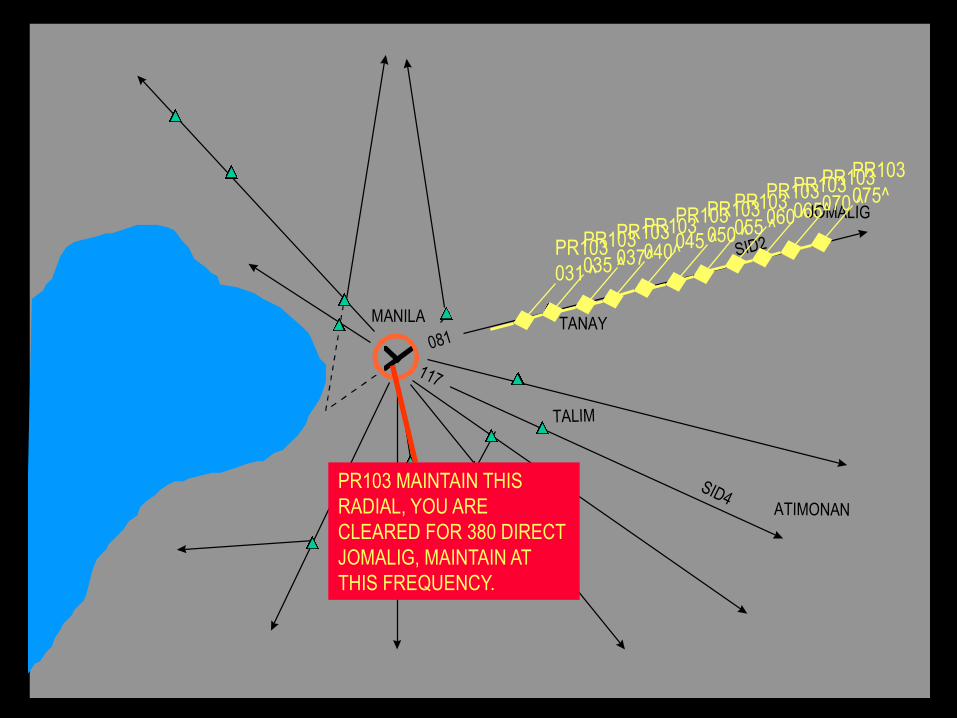
MLA APPROACH THIS IS
PR103 NOW ESTABLISHED
ON RADIAL 081 PASSING
3000 OVER TANAY.
PR103 MAINTAIN THIS
RADIAL, YOU ARE
CLEARED FOR 380 DIRECT
JOMALIG, MAINTAIN AT
THIS FREQUENCY.
117
SID4
TALIM
SID2
TANAY081
JOMALIG
ATIMONAN
MANILA
LIPA
PR103
031 ^
PR103 MAINTAIN THIS
RADIAL, YOU ARE
CLEARED FOR 380 DIRECT
JOMALIG, MAINTAIN AT
THIS FREQUENCY.
PR103
035 ^
PR103
037^
PR103
040^
PR103
045 ^
PR103
050 ^
PR103
055 ^
PR103
060 ^
PR103
065^
PR103
070 ^
PR103
075^

MALAYA
ALABATMANILA
LIPA
JOMALIG
LUBANG
CABANATUAN
ATIMONAN
TALIM
LOPEZ
PR103
075^
PR103
080^
PR103
085^
PR103
095^
PR103
105^
PR103
115^
PR103
130^
PR103
150^
PR103
170^
PR103
210^
PR103
220^
PR103 REQUEST DME
60 DME AND
APPROACHING
JOMALIG

PR103
075^
MLA CONTROL THIS IS
PR103 OVER JOMALIG
PASSING 080 AND
CLIMBING
PR103 WE GOT YOU ON
RADAR, INTERCEPT
RADIAL 093 FOR 380
DIRECT DILIS.

PR103
075^
PR103
085^ PR103
120^ PR103
180^ PR103
200^ PR103
250^ PR103
300^ PR103
350^
MLA CONTROL THIS IS
PR103 OVER DILIS
PASSING 350
PR103 MAINTAIN
PRESENT COURSE,
CONTROL SERVICE
TERMINATED CONTACT
MLARADIO AT 5447khZ
MLA RADIO THIS IS
PR103 OVER DILIS
PASSING 360PR103 MAINTAIN
PRESENT COURSE,
REPORT OVER ENDAX

3. Flight landing (Descent and Final approach)
In order to find the target airport, the pilot receives the frequency
radiated from VOR and DME installed in the airport and checks
the direction indicator for navigation.
The flight must enter the runway straight from the final approach
area (approx. 10 to 20 nm). The runway centerline can be
checked by receiving the frequency from the ILS Localizer.
Together with the Markers or DME, the distance to the landing
point will also be known.
For landing, the flight has to lower the altitude at a specific angle
(3%). This can be checked by receiving the frequency from ILS-
GP that sends the angle data.
Phases of flight with regards to navaids

150
90
OM
MM APPROACH, THIS IS PR102
NOW ESTABLISHED ON
THE LOCALIZER
PR102 YOU ARE NOW 6
DME ON FINAL, CONTACT
TOWER 118.1

MM
OM
90
150MLA TWR, THIS IS PR102
6 DME ON FINAL
PR102 CONTINUE
APPROACH, WIND AT 15
KNOTS, HEADING 240,
QNH AT 1010, VISIBILITY
2 MILES.

MM
OM
90
150
PR102 YOU ARE
CLEARED TO LAND

MM
OM
90
150

Can we land a plane without using ILS?

Approach Lighting System (ALS)
• Simple Approach Lighting System (SALS)
• Precision Approach Lighting System (PALS)
Visual Approach

Simple Approach Lighting System (SALS)
420 m
300 m
60 m
600 m 300 m
APPROACH LIGHTING BEACON
R/W
Cross BarCenter line
Barrette
Precision Approach Lighting System (PALS)
300 m
900 m
APPROACH LIGHTING BEACON
R/W
Cross Bar
Note: Not Drawn to scale
30 m
Center line Barrette
Side Barrette (CAT II & CAT III)
R/W THRESHOLD
LIGHTS
R/W THRESHOLD
LIGHTS

Approach Lighting System (ALS)
Visual Approach

Precision Approach Path indicator( PAPI)
Visual Approach

PAPI
Visual Approach

PAPI
Visual Approach

What is ILS?
An (ILS) Instrument Landing System is a ground-
based equipment that radiates guidance
information to be received by an aircraft during
final approach for correct and safe landing.
Ground-based
Equipment
• Transmitter
• Combining/Dividing
Network
• Transmitting Antenna
• Monitor Systems
Airborne Equipment
• Airborne Receiver
(CDI)
• Receiving Antenna

How ILS works?
1. Ground localizer antenna transmit VHF signal in
direction opposite of runway to horizontally guide aircraft
to the runway centre line.
2. Ground Glide Path antenna transmit UHF signal in
vertical direction to vertically guide aircraft to the
touchdown point.
3. Localizer and Glide Path antenna located at aircraft nose
receives both signals and sends it to ILS indicator in the
cockpit.
4. This signal activate the vertical and horizontal needles
inside the ILS indicator to tell the pilot either go left/right
or go up/down.
5. Keeping both needles at the center, the pilot can guide
his aircraft down to end of landing runway aligned with
the runway center line and aiming the touch down.

A. To provide an aircraft with a precision final approached.
Provide both horizontal and vertical guidance.
B. To guide the pilot to perform landing.
C. It is very helpful when visibility is limited and the pilot
cannot see the airport and runway.
D. To help the aircraft to a runway touchdown point.
E. To ensure flight safety.
What is the importance of ILS?

KOREAN AIR GUAM
CRASH
August, 1997
0123456
318
363
954
1250
1600
ILS - GLIDESLOPE
EQUIPMENT NOT
OPERATIONAL
954
1250

KOREAN AIR GUAM
CRASH
August, 1997
0123456
318
363
954
1250
1600
ILS - GLIDESLOPE
EQUIPMENT NOT
OPERATIONAL
954
1250

KOREAN AIR GUAM
CRASH
August, 1997
0123456
318
363
954
1250
1600
ILS - GLIDESLOPE
EQUIPMENT NOT
OPERATIONAL
954
1250
200+ KILLED
22 SURVIVORS

Instrument Landing System
Standard precision approach system
VHF LOCALIZER
• Provides centerline information.
• 108.1 to 111.975 MHz
• Modulated by 90 and 150 Hz as
navigation tones at 20% each.
• Modulated by 1020 Hz tone at 5% in
Morse Code as station ID.
ILS

Instrument Landing System
Standard precision approach system
UHF Glide Slope
• Provides glide path information
• 328.6 to 335.4 MHz with 50kHz
interval channel
• Modulated by 90 and 150 Hz
navigational tone at 40% each.
ILS

Instrument Landing System
Standard precision approach system
Terminal DME (T-DME)
• Provides distance information
• Uses 960 to 1215 MHz carrier frequency
ILS

Instrument Landing System
Standard precision approach system
VHF Markers
• Provides distance information
• 75 MHz carrier frequency
• Outer marker is modulated by 400 Hz
tone as series of dashes
• Middle marker is modulated by 1020 Hz
tone alternate dots and dashes
ILS

ILS Arrangements on Airports
0.155
0.155
Approximately 4 ½ miles
Administration building
Glide-path Antenna &
DME Antenna
Localizer Antenna
1000’
(approx)
Localizer shelter
RunwayMiddle Marker Outer Marker
1000’
3500’(approx)
Direction of
Approach

ILS Operational Category
RVR or VIS
DH 60 m (200ft) RVR 550 m or VIS 800 mCAT I
DH 30 m (100ft) RVR 350 mCAT II
DH 30 m (100 ft)
Or No DH
RVR 200 mCAT III A
CAT III B DH < 15 m (50 ft) or
No DH
CAT III C No RVR Limitations
No DH
RVR 50 m
DHCategory
DH : Decision Height
RVR: Runway Visual Range
VIS: Visibility
ILS is classified according to its performance. The pilot should be able to see the Runway facilities
before reaching the decision height (DH) otherwise he has to make his own decision whether to
continue to land or to misapproach.

Relationship between category performance and the
decision height (DH) point
DH = 30m
DH = 60m
MMIM
MSL
TDZ level
RA
CAT I
CAT II
Go Around
Go Around
DA=TDZ+DHILS REF DATUM
NOTE:
RA: Radio Altimeter
TCH: Threshold closing height (distance from ground to ILS RER datum) TCH = 15 m (+ 3 m)
TDZ: Touch Down Zone level (DH uses Runway elevation
MSL: Mean Sea Level

AM SIGNALS RADIATED BY ILS EQUIPMENT
SBO SIGNALS
CSB SIGNALS
Ec
Ecs90Ecs150
Ecs90
Ecs150 Ecs90
Ecs150or

LLZ ANT
Ec
Ecs90Ecs150
Ecs90
Ecs150Ecs90
Ecs150
LEFT RIGHT
150 Hz < 90 Hz 150 Hz = 90 Hz 150 Hz > 90 Hz
Course Deviation
Indicator (CDI)

COMBINED SIGNAL IN SPACE (space modulation)
Ecs90
Ecs150Ecs90
Ecs150
LEFT RIGHT
150 Hz < 90 Hz 150 Hz = 90 Hz 150 Hz > 90 Hz
CENTER
Ec
Ecs90Ecs150
Ec
Ecs90Ecs150
Ec
Ecs90Ecs150
Ec
Ecs90
Ecs150
Ec
Ecs90
Ecs150
SB
CAR
SPACE
MODULATED
Ec
Ecs90Ecs150
NO SIDEBAND

Ec
Ecs90Ecs150
Ecs90
Ecs150
Ecs90
Ecs150
SB
SBCAR
150 Hz > 90 Hz
150 Hz = 90 Hz
150 Hz < 90 Hz
GP RADIATION PATTERN AND PRINCIPLE (null /sb reference)
GLIDESLOPE CONCEPT

10/29/2015
Ecs90
Ecs150 Ecs90
Ecs150
BELOW GP ABOVE GP
150 Hz < 90 Hz150 Hz = 90 Hz150 Hz > 90 Hz
ON GP
Ec
Ecs90Ecs150
Ec
Ecs90Ecs150
Ec
Ecs90Ecs150
Ec
Ecs90
Ecs150
Ec
Ecs90
Ecs150
CAR
SB
SPACE
MODULATE
D
Ec
Ecs90Ecs150
NO SIDEBAND

Ec
Ecs90Ecs150
CAR
Eclss150
Ecl
Ec
Ecs90
Ecs150
SB
Ec
Ecs90
Ecs150
SB
Clearance
area
Directional
Area
GP RADIATION PATTERN
CL

OM
MM
IM
OM
MM
IM
OM
MM
IM
IM: Inner Marker
RF: 75 MHz
Signal: 3000 Hz
Mod: 95%
Power: 1 Watt
Keying: ••••••
OM: Outer Marker
RF: 75 MHz
Signal: 400 Hz
Mod: 95%
Power: 3 Watts
Keying: ― ― ― ―
IM: Middle Marker
RF: 75 MHz
Signal: 1300 Hz
Mod: 95%
Power: 1 Watt
Keying: •― •― •―
white
blue
orange
MARKER BEACONS
Runway
IM
MM
OM
~ 7km
~ 1km
~ 450m

0.155
0.155
GP AntennaLLZ Antenna
Runway
Middle Marker Outer MarkerInner Marker
Point A
Point BPoint C
Zone 3 Zone 2 Zone 1Zone 4
Zone 3(cat II,III)
Point D
900 m
4 m 30 m
ILS POINTS AND ZONES

Runway
-150μA
+150μA
Course Width210 m
LLZ COURSE WIDTH
The course width is measured 210 m above the runway threshold. Along the loci of points, a ± 150 μA (0.155 DDM) should be at CDI display.
RIGHT
LEFT

-75μA
+150μA
Path Width (±0.72°)
GLIDE PATH WIDTH
The path width is determined by loci of points
having a DDM of 0.0875 DDM or ±75μA at the
CDI display +75μA
GP Angle (3°)

DDM and SDM
DDM is the difference of depth of modulation
of the larger signal minus the smaller signal
divided by 100 while SDM is the sum of
modulation of the signals anywhere in the
plane.
Runway
GP
LLZ
threshold
06
24
M90Hz<M150Hz
27.75%-12.25%100
M150Hz>M90Hz
0.155DDM150A
27.75%-12.25%100
SDM = = 40%


Factors affected ILS signals
Weather
Snow and heavy rain attenuates the ILS signals thereby reducing
the accuracy.
FM broadcasts
FM transmitters (radio stations) have wide bandwidths and it is
possible for such stations transmitting on same frequencies that
causing interference with the ILS signals.
Vehicle or aircraft movement on the ground.
Every ILS installation has its critical area and its sensitive area.
The critical area is protected during all ILS operations because the
presence of vehicles or aircraft inside its boundaries will cause
unacceptable disturbance to the ILS signals.
Thus, these areas are important to prevent ILS signal disturbance.


Sky Maru System 100-LLZ & GP: Brief Description
ILS-LZZ and GP of KAC was developed in 2008
Is based on flexible modular concept
This system adapted modern digital technology
Uses high speed micro processing & integrated circuit device
Fully compliant with ICAO Annex 10 & FAA Order

Sky Maru System 100-LLZ: Features

LLZ System Equipment Set up
Local Control & Monitor Set-up
Remote Control &
Monitor Set-up
Remote Mo
nitor Set-up
Antenna
Set-up
ADU CMU
20 Array
LPDA

Sky Maru System 100 at Laguindingan Airport

THANKS FOR LISTENING


